EP3971469A1 - A vehicle headlamp assembly - Google Patents
A vehicle headlamp assembly Download PDFInfo
- Publication number
- EP3971469A1 EP3971469A1 EP21198041.2A EP21198041A EP3971469A1 EP 3971469 A1 EP3971469 A1 EP 3971469A1 EP 21198041 A EP21198041 A EP 21198041A EP 3971469 A1 EP3971469 A1 EP 3971469A1
- Authority
- EP
- European Patent Office
- Prior art keywords
- lens
- lens surface
- light
- high beam
- vehicle headlamp
- Prior art date
- Legal status (The legal status is an assumption and is not a legal conclusion. Google has not performed a legal analysis and makes no representation as to the accuracy of the status listed.)
- Granted
Links
Images


Classifications
-
- F—MECHANICAL ENGINEERING; LIGHTING; HEATING; WEAPONS; BLASTING
- F21—LIGHTING
- F21S—NON-PORTABLE LIGHTING DEVICES; SYSTEMS THEREOF; VEHICLE LIGHTING DEVICES SPECIALLY ADAPTED FOR VEHICLE EXTERIORS
- F21S41/00—Illuminating devices specially adapted for vehicle exteriors, e.g. headlamps
- F21S41/20—Illuminating devices specially adapted for vehicle exteriors, e.g. headlamps characterised by refractors, transparent cover plates, light guides or filters
- F21S41/25—Projection lenses
- F21S41/255—Lenses with a front view of circular or truncated circular outline
-
- F—MECHANICAL ENGINEERING; LIGHTING; HEATING; WEAPONS; BLASTING
- F21—LIGHTING
- F21S—NON-PORTABLE LIGHTING DEVICES; SYSTEMS THEREOF; VEHICLE LIGHTING DEVICES SPECIALLY ADAPTED FOR VEHICLE EXTERIORS
- F21S41/00—Illuminating devices specially adapted for vehicle exteriors, e.g. headlamps
- F21S41/10—Illuminating devices specially adapted for vehicle exteriors, e.g. headlamps characterised by the light source
- F21S41/14—Illuminating devices specially adapted for vehicle exteriors, e.g. headlamps characterised by the light source characterised by the type of light source
- F21S41/141—Light emitting diodes [LED]
- F21S41/143—Light emitting diodes [LED] the main emission direction of the LED being parallel to the optical axis of the illuminating device
-
- F—MECHANICAL ENGINEERING; LIGHTING; HEATING; WEAPONS; BLASTING
- F21—LIGHTING
- F21S—NON-PORTABLE LIGHTING DEVICES; SYSTEMS THEREOF; VEHICLE LIGHTING DEVICES SPECIALLY ADAPTED FOR VEHICLE EXTERIORS
- F21S41/00—Illuminating devices specially adapted for vehicle exteriors, e.g. headlamps
- F21S41/10—Illuminating devices specially adapted for vehicle exteriors, e.g. headlamps characterised by the light source
- F21S41/14—Illuminating devices specially adapted for vehicle exteriors, e.g. headlamps characterised by the light source characterised by the type of light source
- F21S41/141—Light emitting diodes [LED]
- F21S41/151—Light emitting diodes [LED] arranged in one or more lines
-
- F—MECHANICAL ENGINEERING; LIGHTING; HEATING; WEAPONS; BLASTING
- F21—LIGHTING
- F21S—NON-PORTABLE LIGHTING DEVICES; SYSTEMS THEREOF; VEHICLE LIGHTING DEVICES SPECIALLY ADAPTED FOR VEHICLE EXTERIORS
- F21S41/00—Illuminating devices specially adapted for vehicle exteriors, e.g. headlamps
- F21S41/20—Illuminating devices specially adapted for vehicle exteriors, e.g. headlamps characterised by refractors, transparent cover plates, light guides or filters
- F21S41/285—Refractors, transparent cover plates, light guides or filters not provided in groups F21S41/24 - F21S41/2805
-
- F—MECHANICAL ENGINEERING; LIGHTING; HEATING; WEAPONS; BLASTING
- F21—LIGHTING
- F21S—NON-PORTABLE LIGHTING DEVICES; SYSTEMS THEREOF; VEHICLE LIGHTING DEVICES SPECIALLY ADAPTED FOR VEHICLE EXTERIORS
- F21S41/00—Illuminating devices specially adapted for vehicle exteriors, e.g. headlamps
- F21S41/20—Illuminating devices specially adapted for vehicle exteriors, e.g. headlamps characterised by refractors, transparent cover plates, light guides or filters
- F21S41/29—Attachment thereof
-
- F—MECHANICAL ENGINEERING; LIGHTING; HEATING; WEAPONS; BLASTING
- F21—LIGHTING
- F21S—NON-PORTABLE LIGHTING DEVICES; SYSTEMS THEREOF; VEHICLE LIGHTING DEVICES SPECIALLY ADAPTED FOR VEHICLE EXTERIORS
- F21S41/00—Illuminating devices specially adapted for vehicle exteriors, e.g. headlamps
- F21S41/40—Illuminating devices specially adapted for vehicle exteriors, e.g. headlamps characterised by screens, non-reflecting members, light-shielding members or fixed shades
- F21S41/43—Illuminating devices specially adapted for vehicle exteriors, e.g. headlamps characterised by screens, non-reflecting members, light-shielding members or fixed shades characterised by the shape thereof
-
- F—MECHANICAL ENGINEERING; LIGHTING; HEATING; WEAPONS; BLASTING
- F21—LIGHTING
- F21W—INDEXING SCHEME ASSOCIATED WITH SUBCLASSES F21K, F21L, F21S and F21V, RELATING TO USES OR APPLICATIONS OF LIGHTING DEVICES OR SYSTEMS
- F21W2102/00—Exterior vehicle lighting devices for illuminating purposes
- F21W2102/10—Arrangement or contour of the emitted light
- F21W2102/13—Arrangement or contour of the emitted light for high-beam region or low-beam region
-
- F—MECHANICAL ENGINEERING; LIGHTING; HEATING; WEAPONS; BLASTING
- F21—LIGHTING
- F21W—INDEXING SCHEME ASSOCIATED WITH SUBCLASSES F21K, F21L, F21S and F21V, RELATING TO USES OR APPLICATIONS OF LIGHTING DEVICES OR SYSTEMS
- F21W2102/00—Exterior vehicle lighting devices for illuminating purposes
- F21W2102/10—Arrangement or contour of the emitted light
- F21W2102/13—Arrangement or contour of the emitted light for high-beam region or low-beam region
- F21W2102/135—Arrangement or contour of the emitted light for high-beam region or low-beam region the light having cut-off lines, i.e. clear borderlines between emitted regions and dark regions
- F21W2102/155—Arrangement or contour of the emitted light for high-beam region or low-beam region the light having cut-off lines, i.e. clear borderlines between emitted regions and dark regions having inclined and horizontal cutoff lines
Definitions
- the present disclosure relates to a projector headlamp assembly for an automotive lighting application. More particularly, present disclosure relates to a projector headlamp assembly incorporating a lens unit which aids in light distribution for low beam and high beam function.
- Headlamp systems help in illuminating the space in front of an automobile.
- headlamp systems which include reflector headlamps, projector headlamps, H4 conversions, etc.
- the main function of a headlamp system is to provide appropriate light distribution during a low beam and a high beam function.
- projector type vehicle headlamps include a projection lens that is disposed on an optical axis which extends in a longitudinal direction of a vehicle, a light source which is positioned such that focus of the light source is on the optical axis behind the projector lens and a reflector to converge the light to the focal point of the projection lens.
- the light distribution during a low beam and a high beam function is controlled by using a light shield member.
- the light shield member is positioned in front of a light source of the projector headlamp system.
- the light shield member is positioned in front of the light source to obtain an appropriate light distribution through shielding of light.
- the light shield member is moved away from the light source.
- the light shield member is mechanically shifted, a change in the distribution of light from low beam to high beam occurs which may not be a smooth transition.
- different classes of lighting regulation for example in two-wheeler for Class B, C and D, there is need for different kind of projector lamps.
- LHT left-hand traffic
- RHT right-hand traffic
- the light shield member requires a complicated design in order to produce a change in the amount of light shielded.
- the complicated design of the light shield member may increase the space occupied by the light shield member in the projector-based headlamps.
- the projector headlamp assembly should also be homologated for different classes of regulations across various countries, e.g., ECE 112, ECE 113 and FMVSS 108 by using suitable combinations of light source.
- An embodiment of the present disclosure discloses a vehicle headlamp assembly for an automotive lighting application.
- the vehicle headlamp assembly includes at least one light emitting unit; at least one lens unit and at least one projector lens unit.
- the at least one lens unit is configured to collect and collimate an emitted light from the at least one light emitting unit.
- the at least one lens unit comprises a dual lens, wherein the dual lens comprises a low beam lens surface and a high beam lens surface.
- the low beam lens surface comprises a first part and a second part.
- the first part comprises a collimator region and a total internal reflection region (TIR), and the second part comprises a freeform lens curvature.
- TIR total internal reflection region
- the high beam lens surface also comprises a first part and a second part, wherein the first part comprises a collimator region or a total internal reflection region (TIR), and the second part comprises a freeform lens curvature.
- the at least one projector lens unit is configured to receive the light advanced from the at least one lens unit, and project it towards to an area in front of the vehicles.
- autonomous is defined as a system for transporting people, animals or cargo by road.
- the term is intended to include, but not be limited to, motorized and non-motorized transportation systems, and is also intended to include automobiles with two, three, or more wheels.
- Non-limiting examples of such automobiles may include bicycles, motorcycles, scooters, cars, trucks and the like.
- low beam function is used relation to the vehicle headlamp assembly. It refers to the light projected from the low beam lens surface, where the light projected is generally short range and the light coverage is approximately 70 m, with limits on light directed towards the eyes of the other road users as incoming traffic.
- high beam is used in relation to the vehicle headlamp assembly. It is defined as the light projected from the high beam lens surface, where the light projected is generally of long range and the light coverage is approximately 200 m.
- ECE Economic Commission of Europe
- FMVSS Federal Motor Vehicle Safety Standards
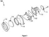
- FIG. 1 illustrates an exploded view (100) of a vehicle headlamp assembly, in accordance with an embodiment of the present disclosure.
- the vehicle headlamp assembly may be a projector-based headlamp.
- the vehicle headlamp assembly may comprise at least one light emitting unit (102), at least one lens unit (104), and at least one projector lens unit.
- the at least one lens unit (104) may be configured to collect and collimate an emitted light from the at least one light emitting unit (102).
- the at least one projector lens unit may be configured to receive a light advanced from the at least one lens unit (104).
- the at least one light emitting unit (102) may comprise a heat sink (110) and a driver assembly (112).
- the light unit (102) may comprise at least one light source soldered into a printed circuit board (PCB) assembly.
- the light source may be a light emitting diode.
- the heat sink (110) may be coupled to the light unit (102) with thermal paste or thermal tape.
- the heat sink may use a passive heat transfer mechanism to suppress the heat generated from the light unit and may transfer the generated heat to environment by natural convection. Further, the heat sink may enable the light unit to operate at permissible temperature range and may further allow the light source to emit the light at optimal efficiency.
- the driver assembly (112) may be connected to the light unit (102). In an alternative embodiment of the present disclosure, the driver assembly (112) may be coupled to the heat sink (110). In one embodiment of the present disclosure, the driver assembly (112) may enable the light unit (102) to operate at a constant current so that there may be no fluctuation in the light intensity at different input voltage. In another embodiment of the present disclosure, the driver assembly (112) may assist in fault detection of light source in short or open condition. For example, the driver assembly may switch off the at least one light source, when any one of the at least one light source may not functioning properly. In another embodiment of the present disclosure, the driver assembly (112) may be also equipped with a noise reducing unit. In one embodiment of the present disclosure, the noise reducing unit may reduce the electromagnetic noises in order to comply with Electromagnetic Interference (EMI) and Electromagnetic compatibility (EMC) automotive regulatory standards.
- EMI Electromagnetic Interference
- EMC Electromagnetic compatibility
- the projector lens unit may comprise a projector lens holder (114), a projector lens (116) and a projector lens cover (118).
- the material of the projector lens (116) may be plastic. In alternative embodiment of the present disclosure, the material of the projector lens (116) may be glass.
- the at least one lens unit (104) may comprise a dual lens.
- Figure 2 illustrates at least one lens unit (104) for the vehicle headlamp assembly, in accordance with an embodiment of the present disclosure.
- the first quadrant (202) and second quadrant (204) in Figure 2 illustrates a side and front view of the dual lens.
- the third quadrant (206) and fourth quadrant (208) in Figure 2 illustrates a top and isometric view of the dual lens.
- the dual lens together may produce different light beam patterns for the left-hand traffic and right-hand traffic.
- the dual lens may comprise a lens holder (203).
- the lens holder (203) may be configured to accommodate low beam lens surface (210) and high beam lens surface (212).
- the low beam lens surface (210) may be integrated with the lens holder (203) as a single piece structure.
- the high beam lens surface (212) may comprise a plurality of rib structures (206).
- the lens holder (203) may comprise a plurality of extending brackets (214a, 214b). In another embodiment, the plurality of extending brackets (214a, 214b) may comprise a C-shaped structure.
- the plurality of rib structures (206) may engage with the plurality of extending brackets (214a, 214b), which may fixate the high beam lens surface (212) to the lens holder (203). Further, the high beam lens surface (212) may be fixated perpendicular to the lens holder (203).
- the low beam lens surface (210) may provide a distribution of light with forward and lateral illumination on road.
- the low beam light may be generally used within city and on countryside roads.
- the high beam lens surface (212) provides a bright, center-weighted distribution of light. The high beam light is generally used on highways and with no incoming traffic.
- Figure 3 illustrates an exemplary optical design of the low beam lens surface (210), in accordance with an embodiment of the present disclosure.
- the low beam lens surface (210) may comprise a first part (302) of the low beam lens surface (210) and a second part (304) of the low beam lens surface (210).
- the first part (302) may be equipped to the light unit (102), and the second part (304) may be located at a distal end from the first part (302).
- the first part (302) may be configured to collect the light from the light unit (102) and collimate it to second part (304).
- the second part (304) may transmit the collimated light to the projector lens (116).
- the first part (302) may comprise a collimator region and a total internal reflection region (TIR).
- the second part (304) may comprise a freeform lens curvature to provide a horizontal light pattern and a vertical light pattern for different classes of lighting regulation.
- the first part (302) and the second part (304) may face in a direction of the optical axis.
- the freeform lens curvature of the low beam lens surface (210) may be designed in such a manner that amount of low beam light falling on the high beam lens surface (212) may be minimum.
- Examples of different classes of lighting regulation may include, but not limited to, ECE 113 Class B, C & D, ECE 112 Class B or FMVSS 108.
- the low beam lens surface (300) may be designed within the same dimensions of the projector lens (116), the at least one lens unit (104), the light unit (102), to make the low beam lens surface (300) suitable across different classes of lighting regulation.
- Figure 4 illustrates an exemplary optical design of the high beam lens surface (400), in accordance with an embodiment of the present disclosure.
- the high beam lens surface (212) may comprise a first part (402) of the high beam lens surface (212) and a second part (404) of the high beam lens surface (212).
- the first part (402) and the second part (404) may be made up of different type of optical surfaces.
- the first part (402) may comprise a collimator region and a TIR (total internal reflection) region.
- the first part (402) may be configured to collect the light emitted from the light unit (102).
- the second part (404) may concentrate the collimated light from the first part (402) to the projector lens (116).
- the second part (404) may comprise a freeform lens curvature to meet the lighting regulation for different classes of light regulation. Further, the first part (402) and the second part (404) may face in the direction of the optical axis. Further, the second part (404) may comprise an elongated structure. Further, the elongated structure may be configured to direct at least a portion of low beam light incident on the top of the freeform curvature of the high beam lens surface (400) towards the projector lens (116). Further, directing of at least a portion of low beam light incident towards the projector lens (116) may increase the intensity of the low beam light, which may increase the overall efficiency of the headlamp.
- the freeform curvature of the high beam lens surface directs remaining portion of low beam light incident on the top of the freeform curvature of the high beam lens surface (400) towards the projector lens holder (114). Further, the directing of the incident low beam light towards the projector lens holder (114). may avoid unnecessary reflections, thereby eliminating glaring effect. Therefore, the freeform curvature of the high beam lens surface (400) may act as a shield for the incident low beam light, which may also eliminate the need of an additional light shielding member.
- Examples of different classes of lighting regulation may include, but not limited to, ECE 113 Class B, C & D, ECE 112 Class B or FMVSS 108.
- the high beam lens surface (400) may be designed within the same dimensions of the at least one lens unit (104), the light unit (102) and the projector lens (116), to make the high beam lens surface (400) suitable across different classes of lighting regulation.
- the material of the low beam and high beam optical parts may be selected from but not limited to plastic such as poly (methyl methacrylate) (PMMA), polycarbonate (PC) and the like.
- the dual lens together can produce different versions of low beam and high beam patterns.
- Figures 5 and 6 which illustrates a symmetric low beam light distribution (500) and an asymmetric low beam light distribution (600) by the vehicle headlamp assembly, in accordance with an embodiment of the present disclosure.
- the low beam light distribution achieved may fall within the classes of lighting regulation comprising, but not limited to, ECE 113 Class B, C & D, ECE 112 Class B or FMVSS 108.
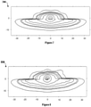
- FIG. 7 and 8 illustrates a symmetric high beam light distribution (700) and an asymmetric high beam light distribution (800) by the vehicle headlamp assembly, in accordance with an embodiment of the present disclosure.
- the low beam light distribution achieved may fall within the classes of lighting regulation comprising, but not limited to, ECE 113 Class B, C & D, ECE 112 Class B or FMVSS 108.
Landscapes
- Engineering & Computer Science (AREA)
- General Engineering & Computer Science (AREA)
- Physics & Mathematics (AREA)
- Microelectronics & Electronic Packaging (AREA)
- Optics & Photonics (AREA)
- Non-Portable Lighting Devices Or Systems Thereof (AREA)
Abstract
Description
- The present application claims priority from the
Indian patent application 202021040968, filed on 22nd September 2020 - The present disclosure relates to a projector headlamp assembly for an automotive lighting application. More particularly, present disclosure relates to a projector headlamp assembly incorporating a lens unit which aids in light distribution for low beam and high beam function.
- The subject matter discussed in the background section should not be assumed to be prior art merely as a result of its mention in the background section. Similarly, a problem mentioned in the background section or associated with the subject matter of the background section should not be assumed to have been previously recognized in the prior art. The subject matter in the background section merely represents different approaches, which in and of themselves may also correspond to implementations of the claimed technology.
- Headlamp systems help in illuminating the space in front of an automobile. There are many kinds of headlamp systems which include reflector headlamps, projector headlamps, H4 conversions, etc. The main function of a headlamp system is to provide appropriate light distribution during a low beam and a high beam function.
- In general, projector type vehicle headlamps include a projection lens that is disposed on an optical axis which extends in a longitudinal direction of a vehicle, a light source which is positioned such that focus of the light source is on the optical axis behind the projector lens and a reflector to converge the light to the focal point of the projection lens.
- In conventional projector-based headlamps, the light distribution during a low beam and a high beam function is controlled by using a light shield member. Typically, the light shield member is positioned in front of a light source of the projector headlamp system. During a low beam function, the light shield member is positioned in front of the light source to obtain an appropriate light distribution through shielding of light. However, during a high beam function, the light shield member is moved away from the light source. When the light shield member is mechanically shifted, a change in the distribution of light from low beam to high beam occurs which may not be a smooth transition. Further for different classes of lighting regulation, for example in two-wheeler for Class B, C and D, there is need for different kind of projector lamps. Different kinds of projector lamps are also required in four-wheelers suited for left-hand traffic (LHT) and right-hand traffic (RHT). For different projector lamps, the light shield member requires a complicated design in order to produce a change in the amount of light shielded. The complicated design of the light shield member may increase the space occupied by the light shield member in the projector-based headlamps.
- Therefore, there exist a need for a projector headlamp assembly which aids in light distribution for low beam and high beam function. In addition, the projector headlamp assembly should also be homologated for different classes of regulations across various countries, e.g., ECE 112, ECE 113 and FMVSS 108 by using suitable combinations of light source.
- This summary is provided to introduce concepts related to a vehicle headlamp assembly and the concepts are further described below in the detailed description. This summary is not intended to identify essential features of the claimed subject matter nor is it intended for use in determining or limiting the scope of the claimed subject matter.
- An embodiment of the present disclosure discloses a vehicle headlamp assembly for an automotive lighting application. The vehicle headlamp assembly includes at least one light emitting unit; at least one lens unit and at least one projector lens unit. The at least one lens unit is configured to collect and collimate an emitted light from the at least one light emitting unit. Further, the at least one lens unit comprises a dual lens, wherein the dual lens comprises a low beam lens surface and a high beam lens surface. Further, the low beam lens surface comprises a first part and a second part. Further, the first part comprises a collimator region and a total internal reflection region (TIR), and the second part comprises a freeform lens curvature. Further, the high beam lens surface also comprises a first part and a second part, wherein the first part comprises a collimator region or a total internal reflection region (TIR), and the second part comprises a freeform lens curvature. Further, the at least one projector lens unit is configured to receive the light advanced from the at least one lens unit, and project it towards to an area in front of the vehicles.
- The foregoing and other features of embodiments of the present disclosure will become more apparent from the following detailed description of embodiments when read in conjunction with the accompanying drawings. In the drawings, like reference numerals refer to like elements.
-
Figure 1 illustrates an explodedview 100 of a vehicle headlamp assembly, in accordance with an embodiment of the present disclosure. -
Figure 2 illustrates various projections (200) of at least one lens unit for the vehicle headlamp assembly, in accordance with an embodiment of the present disclosure. -
Figure 3 illustrates an exemplary optical design (300) of a low beam lens surface for a vehicle headlamp assembly, in accordance with an embodiment of the present disclosure. -
Figure 4 illustrates an exemplary optical design (400) of a high beam lens surface for a vehicle headlamp assembly, in accordance with an embodiment of the present disclosure. -
Figure 5 illustrates a symmetric low beam light distribution (500) by the vehicle headlamp assembly, in accordance with an embodiment of the present disclosure. -
Figure 6 illustrates an asymmetric low beam light distribution (600) by the vehicle headlamp assembly, in accordance with an embodiment of the present disclosure. -
Figure 7 illustrates a symmetric high beam light distribution (700) by the vehicle headlamp assembly, in accordance with an embodiment of the present disclosure. -
Figure 8 illustrates an asymmetric high beam light distribution (800) by the vehicle headlamp assembly, in accordance with an embodiment of the present disclosure. - In the following detailed description, reference is made to the accompanying drawings that form a part hereof, and in which are shown by way of illustration specific embodiments that may be practiced. These embodiments are described in sufficient detail to enable a person skilled in the art to practice the present disclosure, and it is to be understood that other embodiments may be utilized, and that logical, mechanical, and other changes may be made within the scope of the embodiments. Also, the words "comprising," "having," "containing," and "including," and other similar forms are intended to be equivalent in meaning and be open-ended in that an item or items following any one of these words is not meant to be an exhaustive listing of such item or items or meant to be limited to only the listed item or items. The singular forms "a," "an," and "the" include plural references unless the context clearly dictates otherwise. The following detailed description is, therefore, not be taken as limiting the scope of the present disclosure, but instead the present disclosure is to be defined by the appended claims.
- As used herein the term "automobile" is defined as a system for transporting people, animals or cargo by road. The term is intended to include, but not be limited to, motorized and non-motorized transportation systems, and is also intended to include automobiles with two, three, or more wheels. Non-limiting examples of such automobiles may include bicycles, motorcycles, scooters, cars, trucks and the like.
- The term "low beam function" is used relation to the vehicle headlamp assembly. It refers to the light projected from the low beam lens surface, where the light projected is generally short range and the light coverage is approximately 70 m, with limits on light directed towards the eyes of the other road users as incoming traffic.
- The term "high beam" is used in relation to the vehicle headlamp assembly. It is defined as the light projected from the high beam lens surface, where the light projected is generally of long range and the light coverage is approximately 200 m.
- The term "ECE" or "Economic Commission of Europe" is used in relation to the vehicle headlamp assembly. It provides for a vehicle regulatory framework for member countries of United Nations.
- The term "FMVSS" or "Federal Motor Vehicle Safety Standards" is used in relation to the vehicle headlamp. It provides for a specification of the design, construction, performance and durability requirements for a motor vehicle and its components in United States of America.
-
Figure 1 illustrates an exploded view (100) of a vehicle headlamp assembly, in accordance with an embodiment of the present disclosure. It must be noted, the vehicle headlamp assembly may be a projector-based headlamp. The vehicle headlamp assembly may comprise at least one light emitting unit (102), at least one lens unit (104), and at least one projector lens unit. Further, the at least one lens unit (104) may be configured to collect and collimate an emitted light from the at least one light emitting unit (102). Further, the at least one projector lens unit may be configured to receive a light advanced from the at least one lens unit (104). - In one embodiment of the present disclosure, the at least one light emitting unit (102) may comprise a heat sink (110) and a driver assembly (112). In an embodiment of the present disclosure, the light unit (102) may comprise at least one light source soldered into a printed circuit board (PCB) assembly. In one embodiment of the present disclosure, the light source may be a light emitting diode.
- In an embodiment of the present disclosure, the heat sink (110) may be coupled to the light unit (102) with thermal paste or thermal tape. In another embodiment of the present disclosure, the heat sink may use a passive heat transfer mechanism to suppress the heat generated from the light unit and may transfer the generated heat to environment by natural convection. Further, the heat sink may enable the light unit to operate at permissible temperature range and may further allow the light source to emit the light at optimal efficiency.
- In one embodiment of the present disclosure, the driver assembly (112) may be connected to the light unit (102). In an alternative embodiment of the present disclosure, the driver assembly (112) may be coupled to the heat sink (110). In one embodiment of the present disclosure, the driver assembly (112) may enable the light unit (102) to operate at a constant current so that there may be no fluctuation in the light intensity at different input voltage. In another embodiment of the present disclosure, the driver assembly (112) may assist in fault detection of light source in short or open condition. For example, the driver assembly may switch off the at least one light source, when any one of the at least one light source may not functioning properly. In another embodiment of the present disclosure, the driver assembly (112) may be also equipped with a noise reducing unit. In one embodiment of the present disclosure, the noise reducing unit may reduce the electromagnetic noises in order to comply with Electromagnetic Interference (EMI) and Electromagnetic compatibility (EMC) automotive regulatory standards.
- In an embodiment of the present disclosure, the projector lens unit may comprise a projector lens holder (114), a projector lens (116) and a projector lens cover (118). In an embodiment of the present disclosure, the material of the projector lens (116) may be plastic. In alternative embodiment of the present disclosure, the material of the projector lens (116) may be glass.
- In an embodiment of the present disclosure, the at least one lens unit (104) may comprise a dual lens.
Figure 2 illustrates at least one lens unit (104) for the vehicle headlamp assembly, in accordance with an embodiment of the present disclosure. The first quadrant (202) and second quadrant (204) inFigure 2 illustrates a side and front view of the dual lens. The third quadrant (206) and fourth quadrant (208) inFigure 2 illustrates a top and isometric view of the dual lens. In an embodiment of the present disclosure, the dual lens together may produce different light beam patterns for the left-hand traffic and right-hand traffic. - In one embodiment of the present disclosure, the dual lens may comprise a lens holder (203). Further, the lens holder (203) may be configured to accommodate low beam lens surface (210) and high beam lens surface (212). Further, the low beam lens surface (210) may be integrated with the lens holder (203) as a single piece structure. Further, the high beam lens surface (212) may comprise a plurality of rib structures (206). Further, the lens holder (203) may comprise a plurality of extending brackets (214a, 214b). In another embodiment, the plurality of extending brackets (214a, 214b) may comprise a C-shaped structure. Further, the plurality of rib structures (206) may engage with the plurality of extending brackets (214a, 214b), which may fixate the high beam lens surface (212) to the lens holder (203). Further, the high beam lens surface (212) may be fixated perpendicular to the lens holder (203).
- In another embodiment of the present disclosure, the low beam lens surface (210) may provide a distribution of light with forward and lateral illumination on road. The low beam light may be generally used within city and on countryside roads. In another embodiment of the present disclosure, the high beam lens surface (212) provides a bright, center-weighted distribution of light. The high beam light is generally used on highways and with no incoming traffic.
-
Figure 3 illustrates an exemplary optical design of the low beam lens surface (210), in accordance with an embodiment of the present disclosure. In one embodiment of the present disclosure, the low beam lens surface (210) may comprise a first part (302) of the low beam lens surface (210) and a second part (304) of the low beam lens surface (210). Further, the first part (302) may be equipped to the light unit (102), and the second part (304) may be located at a distal end from the first part (302). Further, the first part (302) may be configured to collect the light from the light unit (102) and collimate it to second part (304). The second part (304) may transmit the collimated light to the projector lens (116). In an embodiment of the present disclosure, the first part (302) may comprise a collimator region and a total internal reflection region (TIR). Further, the second part (304) may comprise a freeform lens curvature to provide a horizontal light pattern and a vertical light pattern for different classes of lighting regulation. Further, the first part (302) and the second part (304) may face in a direction of the optical axis. Further, the freeform lens curvature of the low beam lens surface (210) may be designed in such a manner that amount of low beam light falling on the high beam lens surface (212) may be minimum. - Examples of different classes of lighting regulation may include, but not limited to, ECE 113 Class B, C & D,
ECE 112 Class B or FMVSS 108. In an embodiment of the present disclosure, the low beam lens surface (300), may be designed within the same dimensions of the projector lens (116), the at least one lens unit (104), the light unit (102), to make the low beam lens surface (300) suitable across different classes of lighting regulation. -
Figure 4 illustrates an exemplary optical design of the high beam lens surface (400), in accordance with an embodiment of the present disclosure. Further, the high beam lens surface (212) may comprise a first part (402) of the high beam lens surface (212) and a second part (404) of the high beam lens surface (212). Further, the first part (402) and the second part (404) may be made up of different type of optical surfaces. In an embodiment of the present disclosure, the first part (402) may comprise a collimator region and a TIR (total internal reflection) region. Further, the first part (402) may be configured to collect the light emitted from the light unit (102). Further, the second part (404) may concentrate the collimated light from the first part (402) to the projector lens (116). In an embodiment of the present disclosure, the second part (404) may comprise a freeform lens curvature to meet the lighting regulation for different classes of light regulation. Further, the first part (402) and the second part (404) may face in the direction of the optical axis. Further, the second part (404) may comprise an elongated structure. Further, the elongated structure may be configured to direct at least a portion of low beam light incident on the top of the freeform curvature of the high beam lens surface (400) towards the projector lens (116). Further, directing of at least a portion of low beam light incident towards the projector lens (116) may increase the intensity of the low beam light, which may increase the overall efficiency of the headlamp. In an embodiment of the present disclosure, the freeform curvature of the high beam lens surface directs remaining portion of low beam light incident on the top of the freeform curvature of the high beam lens surface (400) towards the projector lens holder (114). Further, the directing of the incident low beam light towards the projector lens holder (114). may avoid unnecessary reflections, thereby eliminating glaring effect. Therefore, the freeform curvature of the high beam lens surface (400) may act as a shield for the incident low beam light, which may also eliminate the need of an additional light shielding member. - Examples of different classes of lighting regulation may include, but not limited to, ECE 113 Class B, C & D,
ECE 112 Class B or FMVSS 108. Within the same boundary of the lamp system. In an embodiment of the present disclosure, the high beam lens surface (400), may be designed within the same dimensions of the at least one lens unit (104), the light unit (102) and the projector lens (116), to make the high beam lens surface (400) suitable across different classes of lighting regulation. - In an embodiment of the present disclosure, the material of the low beam and high beam optical parts may be selected from but not limited to plastic such as poly (methyl methacrylate) (PMMA), polycarbonate (PC) and the like.
- In an embodiment of the present disclosure, the dual lens together can produce different versions of low beam and high beam patterns. Now referring to
Figures 5 and 6 , which illustrates a symmetric low beam light distribution (500) and an asymmetric low beam light distribution (600) by the vehicle headlamp assembly, in accordance with an embodiment of the present disclosure. Further, it may be seen that the low beam light distribution achieved may fall within the classes of lighting regulation comprising, but not limited to, ECE 113 Class B, C & D,ECE 112 Class B or FMVSS 108. - Now referring to
Figures 7 and 8 , which illustrates a symmetric high beam light distribution (700) and an asymmetric high beam light distribution (800) by the vehicle headlamp assembly, in accordance with an embodiment of the present disclosure. Further, it may be seen that the low beam light distribution achieved may fall within the classes of lighting regulation comprising, but not limited to, ECE 113 Class B, C & D,ECE 112 Class B or FMVSS 108. - The foregoing description of the preferred embodiment of the present disclosure has been presented for the purpose of illustration and description. It is not intended to be exhaustive or to limit the disclosure to the precise form disclosed. Furthermore, all examples recited herein are principally intended expressly to be only for pedagogical purposes to aid the reader in understanding the principles of the present subject matter and are to be construed as being without limitation to such specifically recited examples and conditions. Many modifications and variations are possible in light of the above teachings. It is intended that the scope of the present disclosure not to be limited by this detailed description.
Claims (9)
- A vehicle headlamp assembly comprising:at least one light unit (102);at least one lens unit (104) configured to collect and collimate an emitted light from the at least one light unit (102), wherein the lens unit (104) comprises a dual lens (200), wherein the dual lens (200) comprises a low beam lens surface (210) and a high beam lens surface (212), whereinthe low beam lens surface (210) comprises a first part (302) and a second part (304), wherein the first part (302) comprises a collimator region and a total internal reflection region (TIR), and the second part (304) comprises a freeform curvature; andthe high beam lens surface comprises a first part (402) and a second part (404), wherein the first part (402) comprises a collimator region and a total internal reflection region (TIR), and the second part (404) comprises a freeform curvature.
- The vehicle headlamp assembly as claimed in claim 1, further comprising:a projector lens (116),wherein the freeform curvature of the high beam lens surface (400) comprises an elongated structure that directs at least a portion of low beam light incident on the top of the freeform curvature of the high beam lens surface (400) towards the projector lens (116).
- The vehicle headlamp assembly as claimed in claim 2, further comprising:a projector lens holder (114),wherein the freeform curvature of the high beam lens surface directs remaining portion of low beam light incident on the top of the freeform curvature of the high beam lens surface (400) towards the projector lens holder (114).
- The vehicle headlamp assembly as claimed in claim 1, wherein the dual lens (200) is formed by fixating the low beam lens surface (210) and the high beam lens surface (212) on a lens holder (203).
- The vehicle headlamp assembly as claimed in claim 1, wherein the low beam lens surface (210) is directly integrated on the lens holder (203).
- The vehicle headlamp assembly as claimed in claim 3, wherein the lens holder (203) comprises a plurality of extending brackets (214a, 214b), and wherein the plurality of extending brackets (214a, 214b) comprises a C- shaped structure.
- The vehicle headlamp assembly as claimed in claim 5, wherein the plurality of extending brackets (214a, 214b) are configured to accommodate the freeform structure of the high beam lens surface (212).
- The vehicle headlamp assembly as claimed in claim 1, wherein the high beam lens surface (212) comprises a plurality of rib structures (216).
- The vehicle headlamp assembly as claimed in claim 7, wherein the plurality of rib structures (216) are configured to fit in the plurality of extending brackets (216) of the lens holder (203).
Applications Claiming Priority (1)
| Application Number | Priority Date | Filing Date | Title |
|---|---|---|---|
| IN202021040968 | 2020-09-22 |
Publications (3)
| Publication Number | Publication Date |
|---|---|
| EP3971469A1 true EP3971469A1 (en) | 2022-03-23 |
| EP3971469B1 EP3971469B1 (en) | 2025-08-27 |
| EP3971469C0 EP3971469C0 (en) | 2025-08-27 |
Family
ID=77897481
Family Applications (1)
| Application Number | Title | Priority Date | Filing Date |
|---|---|---|---|
| EP21198041.2A Active EP3971469B1 (en) | 2020-09-22 | 2021-09-21 | A vehicle headlamp assembly |
Country Status (1)
| Country | Link |
|---|---|
| EP (1) | EP3971469B1 (en) |
Citations (8)
| Publication number | Priority date | Publication date | Assignee | Title |
|---|---|---|---|---|
| US20100014304A1 (en) * | 2008-07-16 | 2010-01-21 | OSRAM Gesellschaft mit beschraekter Haftung | Holding frame for an optical element |
| CN106122876A (en) * | 2016-08-24 | 2016-11-16 | 江苏亿诺车辆部件有限公司 | A kind of LED light module reflecting mirror and dark slide conjunction |
| JP2017045552A (en) * | 2015-08-25 | 2017-03-02 | スタンレー電気株式会社 | Vehicle lighting |
| US20190154224A1 (en) * | 2017-11-20 | 2019-05-23 | Valeo Vision | Light module for a vehicle headlight |
| US20190162380A1 (en) * | 2017-11-27 | 2019-05-30 | Valeo Vision | Lighting module for illumination and/or signalling in a motor vehicle |
| EP3502548A1 (en) * | 2017-12-22 | 2019-06-26 | Valeo Vision | Light module for vehicle headlight |
| DE102018110793A1 (en) * | 2018-05-04 | 2019-11-07 | HELLA GmbH & Co. KGaA | projection headlights |
| CN210568140U (en) * | 2019-07-11 | 2020-05-19 | 浙江百康光学股份有限公司 | Double-light lens module, automobile headlamp and vehicle |
-
2021
- 2021-09-21 EP EP21198041.2A patent/EP3971469B1/en active Active
Patent Citations (8)
| Publication number | Priority date | Publication date | Assignee | Title |
|---|---|---|---|---|
| US20100014304A1 (en) * | 2008-07-16 | 2010-01-21 | OSRAM Gesellschaft mit beschraekter Haftung | Holding frame for an optical element |
| JP2017045552A (en) * | 2015-08-25 | 2017-03-02 | スタンレー電気株式会社 | Vehicle lighting |
| CN106122876A (en) * | 2016-08-24 | 2016-11-16 | 江苏亿诺车辆部件有限公司 | A kind of LED light module reflecting mirror and dark slide conjunction |
| US20190154224A1 (en) * | 2017-11-20 | 2019-05-23 | Valeo Vision | Light module for a vehicle headlight |
| US20190162380A1 (en) * | 2017-11-27 | 2019-05-30 | Valeo Vision | Lighting module for illumination and/or signalling in a motor vehicle |
| EP3502548A1 (en) * | 2017-12-22 | 2019-06-26 | Valeo Vision | Light module for vehicle headlight |
| DE102018110793A1 (en) * | 2018-05-04 | 2019-11-07 | HELLA GmbH & Co. KGaA | projection headlights |
| CN210568140U (en) * | 2019-07-11 | 2020-05-19 | 浙江百康光学股份有限公司 | Double-light lens module, automobile headlamp and vehicle |
Also Published As
| Publication number | Publication date |
|---|---|
| EP3971469B1 (en) | 2025-08-27 |
| EP3971469C0 (en) | 2025-08-27 |
Similar Documents
| Publication | Publication Date | Title |
|---|---|---|
| EP2157363B1 (en) | Optical element for vehicle lamp | |
| EP3418626B1 (en) | Lamp and vehicle having same | |
| US7441928B2 (en) | Lighting device | |
| EP2071228A2 (en) | Vehicle lamp assembly | |
| EP3988840B1 (en) | Vehicle lamp | |
| US20100309679A1 (en) | Vehicle headlight | |
| TWI600857B (en) | Light-shielding module that can enhance the light intensity of the car | |
| US20120140503A1 (en) | Head Lamp for Vehicle | |
| CN205991402U (en) | The illuminator of illuminator, motor vehicles illumination and/or signal designation | |
| KR101410878B1 (en) | Head lamp for vehicles | |
| JP6340161B2 (en) | Lighting module that generates interlacing of light strips | |
| KR101405385B1 (en) | Lamp apparatus for an automobile | |
| CN113048443A (en) | Vehicle lamp | |
| EP2075500A2 (en) | Vehicle headlamp | |
| US7572041B2 (en) | Vehicle lamp | |
| KR20160035011A (en) | Lighting system, in particular for a motor vehicle lighting member, comprising integrated leds | |
| KR20190032752A (en) | Lamp for vehicle | |
| EP3971469B1 (en) | A vehicle headlamp assembly | |
| CN105555608B (en) | Lighting device for vehicle | |
| US11732864B2 (en) | Lighting or signaling device and motor vehicle | |
| KR20190033346A (en) | lamp for vehicle | |
| CN103062696A (en) | Optical module of motor vehicle lightning device | |
| KR102555372B1 (en) | Lamp for vehicle | |
| US6955439B2 (en) | Dual filament static bending lamp | |
| KR20140133063A (en) | Automotive lamp assembly |
Legal Events
| Date | Code | Title | Description |
|---|---|---|---|
| PUAI | Public reference made under article 153(3) epc to a published international application that has entered the european phase |
Free format text: ORIGINAL CODE: 0009012 |
|
| STAA | Information on the status of an ep patent application or granted ep patent |
Free format text: STATUS: THE APPLICATION HAS BEEN PUBLISHED |
|
| AK | Designated contracting states |
Kind code of ref document: A1 Designated state(s): AL AT BE BG CH CY CZ DE DK EE ES FI FR GB GR HR HU IE IS IT LI LT LU LV MC MK MT NL NO PL PT RO RS SE SI SK SM TR |
|
| STAA | Information on the status of an ep patent application or granted ep patent |
Free format text: STATUS: REQUEST FOR EXAMINATION WAS MADE |
|
| 17P | Request for examination filed |
Effective date: 20220921 |
|
| RBV | Designated contracting states (corrected) |
Designated state(s): AL AT BE BG CH CY CZ DE DK EE ES FI FR GB GR HR HU IE IS IT LI LT LU LV MC MK MT NL NO PL PT RO RS SE SI SK SM TR |
|
| STAA | Information on the status of an ep patent application or granted ep patent |
Free format text: STATUS: EXAMINATION IS IN PROGRESS |
|
| 17Q | First examination report despatched |
Effective date: 20231006 |
|
| RIC1 | Information provided on ipc code assigned before grant |
Ipc: F21W 102/13 20180101ALI20250228BHEP Ipc: F21W 102/155 20180101ALI20250228BHEP Ipc: F21S 41/29 20180101ALI20250228BHEP Ipc: F21S 41/20 20180101ALI20250228BHEP Ipc: F21S 41/255 20180101ALI20250228BHEP Ipc: F21S 41/151 20180101ALI20250228BHEP Ipc: F21S 41/143 20180101AFI20250228BHEP |
|
| GRAP | Despatch of communication of intention to grant a patent |
Free format text: ORIGINAL CODE: EPIDOSNIGR1 |
|
| STAA | Information on the status of an ep patent application or granted ep patent |
Free format text: STATUS: GRANT OF PATENT IS INTENDED |
|
| INTG | Intention to grant announced |
Effective date: 20250423 |
|
| GRAS | Grant fee paid |
Free format text: ORIGINAL CODE: EPIDOSNIGR3 |
|
| GRAA | (expected) grant |
Free format text: ORIGINAL CODE: 0009210 |
|
| STAA | Information on the status of an ep patent application or granted ep patent |
Free format text: STATUS: THE PATENT HAS BEEN GRANTED |
|
| AK | Designated contracting states |
Kind code of ref document: B1 Designated state(s): AL AT BE BG CH CY CZ DE DK EE ES FI FR GB GR HR HU IE IS IT LI LT LU LV MC MK MT NL NO PL PT RO RS SE SI SK SM TR |
|
| REG | Reference to a national code |
Ref country code: CH Ref legal event code: EP |
|
| REG | Reference to a national code |
Ref country code: DE Ref legal event code: R096 Ref document number: 602021037035 Country of ref document: DE |
|
| REG | Reference to a national code |
Ref country code: IE Ref legal event code: FG4D |
|
| PGFP | Annual fee paid to national office [announced via postgrant information from national office to epo] |
Ref country code: AT Payment date: 20251020 Year of fee payment: 5 |
|
| U01 | Request for unitary effect filed |
Effective date: 20250919 |
|
| U07 | Unitary effect registered |
Designated state(s): AT BE BG DE DK EE FI FR IT LT LU LV MT NL PT RO SE SI Effective date: 20250926 |
|
| U20 | Renewal fee for the european patent with unitary effect paid |
Year of fee payment: 5 Effective date: 20251028 |
|
| PG25 | Lapsed in a contracting state [announced via postgrant information from national office to epo] |
Ref country code: IS Free format text: LAPSE BECAUSE OF FAILURE TO SUBMIT A TRANSLATION OF THE DESCRIPTION OR TO PAY THE FEE WITHIN THE PRESCRIBED TIME-LIMIT Effective date: 20251227 |
|
| PG25 | Lapsed in a contracting state [announced via postgrant information from national office to epo] |
Ref country code: NO Free format text: LAPSE BECAUSE OF FAILURE TO SUBMIT A TRANSLATION OF THE DESCRIPTION OR TO PAY THE FEE WITHIN THE PRESCRIBED TIME-LIMIT Effective date: 20251127 |
|
| PG25 | Lapsed in a contracting state [announced via postgrant information from national office to epo] |
Ref country code: HR Free format text: LAPSE BECAUSE OF FAILURE TO SUBMIT A TRANSLATION OF THE DESCRIPTION OR TO PAY THE FEE WITHIN THE PRESCRIBED TIME-LIMIT Effective date: 20250827 |
|
| PG25 | Lapsed in a contracting state [announced via postgrant information from national office to epo] |
Ref country code: GR Free format text: LAPSE BECAUSE OF FAILURE TO SUBMIT A TRANSLATION OF THE DESCRIPTION OR TO PAY THE FEE WITHIN THE PRESCRIBED TIME-LIMIT Effective date: 20251128 |
|
| PG25 | Lapsed in a contracting state [announced via postgrant information from national office to epo] |
Ref country code: PL Free format text: LAPSE BECAUSE OF FAILURE TO SUBMIT A TRANSLATION OF THE DESCRIPTION OR TO PAY THE FEE WITHIN THE PRESCRIBED TIME-LIMIT Effective date: 20250827 |
|
| PG25 | Lapsed in a contracting state [announced via postgrant information from national office to epo] |
Ref country code: RS Free format text: LAPSE BECAUSE OF FAILURE TO SUBMIT A TRANSLATION OF THE DESCRIPTION OR TO PAY THE FEE WITHIN THE PRESCRIBED TIME-LIMIT Effective date: 20251127 |
|
| PG25 | Lapsed in a contracting state [announced via postgrant information from national office to epo] |
Ref country code: ES Free format text: LAPSE BECAUSE OF FAILURE TO SUBMIT A TRANSLATION OF THE DESCRIPTION OR TO PAY THE FEE WITHIN THE PRESCRIBED TIME-LIMIT Effective date: 20250827 |
|
| PG25 | Lapsed in a contracting state [announced via postgrant information from national office to epo] |
Ref country code: SM Free format text: LAPSE BECAUSE OF FAILURE TO SUBMIT A TRANSLATION OF THE DESCRIPTION OR TO PAY THE FEE WITHIN THE PRESCRIBED TIME-LIMIT Effective date: 20250827 |
|
| PG25 | Lapsed in a contracting state [announced via postgrant information from national office to epo] |
Ref country code: CZ Free format text: LAPSE BECAUSE OF FAILURE TO SUBMIT A TRANSLATION OF THE DESCRIPTION OR TO PAY THE FEE WITHIN THE PRESCRIBED TIME-LIMIT Effective date: 20250827 |
|
| PG25 | Lapsed in a contracting state [announced via postgrant information from national office to epo] |
Ref country code: SK Free format text: LAPSE BECAUSE OF FAILURE TO SUBMIT A TRANSLATION OF THE DESCRIPTION OR TO PAY THE FEE WITHIN THE PRESCRIBED TIME-LIMIT Effective date: 20250827 |
|
| REG | Reference to a national code |
Ref country code: CH Ref legal event code: H13 Free format text: ST27 STATUS EVENT CODE: U-0-0-H10-H13 (AS PROVIDED BY THE NATIONAL OFFICE) Effective date: 20260504 |