EP3971447A1 - Planetengeschwindigkeitsänderungsmechanismus - Google Patents
Planetengeschwindigkeitsänderungsmechanismus Download PDFInfo
- Publication number
- EP3971447A1 EP3971447A1 EP21192502.9A EP21192502A EP3971447A1 EP 3971447 A1 EP3971447 A1 EP 3971447A1 EP 21192502 A EP21192502 A EP 21192502A EP 3971447 A1 EP3971447 A1 EP 3971447A1
- Authority
- EP
- European Patent Office
- Prior art keywords
- speed
- change
- gear
- output shaft
- planet
- Prior art date
- Legal status (The legal status is an assumption and is not a legal conclusion. Google has not performed a legal analysis and makes no representation as to the accuracy of the status listed.)
- Granted
Links
Images


Classifications
-
- F—MECHANICAL ENGINEERING; LIGHTING; HEATING; WEAPONS; BLASTING
- F16—ENGINEERING ELEMENTS AND UNITS; GENERAL MEASURES FOR PRODUCING AND MAINTAINING EFFECTIVE FUNCTIONING OF MACHINES OR INSTALLATIONS; THERMAL INSULATION IN GENERAL
- F16H—GEARING
- F16H35/00—Gearings or mechanisms with other special functional features
- F16H35/10—Arrangements or devices for absorbing overload or preventing damage by overload
-
- F—MECHANICAL ENGINEERING; LIGHTING; HEATING; WEAPONS; BLASTING
- F16—ENGINEERING ELEMENTS AND UNITS; GENERAL MEASURES FOR PRODUCING AND MAINTAINING EFFECTIVE FUNCTIONING OF MACHINES OR INSTALLATIONS; THERMAL INSULATION IN GENERAL
- F16H—GEARING
- F16H3/00—Toothed gearings for conveying rotary motion with variable gear ratio or for reversing rotary motion
- F16H3/44—Toothed gearings for conveying rotary motion with variable gear ratio or for reversing rotary motion using gears having orbital motion
- F16H3/46—Gearings having only two central gears, connected by orbital gears
- F16H3/48—Gearings having only two central gears, connected by orbital gears with single orbital gears or pairs of rigidly-connected orbital gears
-
- F—MECHANICAL ENGINEERING; LIGHTING; HEATING; WEAPONS; BLASTING
- F16—ENGINEERING ELEMENTS AND UNITS; GENERAL MEASURES FOR PRODUCING AND MAINTAINING EFFECTIVE FUNCTIONING OF MACHINES OR INSTALLATIONS; THERMAL INSULATION IN GENERAL
- F16H—GEARING
- F16H3/00—Toothed gearings for conveying rotary motion with variable gear ratio or for reversing rotary motion
- F16H3/44—Toothed gearings for conveying rotary motion with variable gear ratio or for reversing rotary motion using gears having orbital motion
-
- F—MECHANICAL ENGINEERING; LIGHTING; HEATING; WEAPONS; BLASTING
- F16—ENGINEERING ELEMENTS AND UNITS; GENERAL MEASURES FOR PRODUCING AND MAINTAINING EFFECTIVE FUNCTIONING OF MACHINES OR INSTALLATIONS; THERMAL INSULATION IN GENERAL
- F16H—GEARING
- F16H3/00—Toothed gearings for conveying rotary motion with variable gear ratio or for reversing rotary motion
- F16H3/44—Toothed gearings for conveying rotary motion with variable gear ratio or for reversing rotary motion using gears having orbital motion
- F16H3/46—Gearings having only two central gears, connected by orbital gears
- F16H3/58—Gearings having only two central gears, connected by orbital gears with sets of orbital gears, each consisting of two or more intermeshing orbital gears
-
- F—MECHANICAL ENGINEERING; LIGHTING; HEATING; WEAPONS; BLASTING
- F16—ENGINEERING ELEMENTS AND UNITS; GENERAL MEASURES FOR PRODUCING AND MAINTAINING EFFECTIVE FUNCTIONING OF MACHINES OR INSTALLATIONS; THERMAL INSULATION IN GENERAL
- F16H—GEARING
- F16H3/00—Toothed gearings for conveying rotary motion with variable gear ratio or for reversing rotary motion
- F16H3/001—Toothed gearings for conveying rotary motion with variable gear ratio or for reversing rotary motion convertible for varying the gear ratio, e.g. for selecting one of several shafts as the input shaft
-
- F—MECHANICAL ENGINEERING; LIGHTING; HEATING; WEAPONS; BLASTING
- F16—ENGINEERING ELEMENTS AND UNITS; GENERAL MEASURES FOR PRODUCING AND MAINTAINING EFFECTIVE FUNCTIONING OF MACHINES OR INSTALLATIONS; THERMAL INSULATION IN GENERAL
- F16H—GEARING
- F16H37/00—Combinations of mechanical gearings, not provided for in groups F16H1/00 - F16H35/00
- F16H37/02—Combinations of mechanical gearings, not provided for in groups F16H1/00 - F16H35/00 comprising essentially only toothed or friction gearings
- F16H37/04—Combinations of toothed gearings only
-
- F—MECHANICAL ENGINEERING; LIGHTING; HEATING; WEAPONS; BLASTING
- F16—ENGINEERING ELEMENTS AND UNITS; GENERAL MEASURES FOR PRODUCING AND MAINTAINING EFFECTIVE FUNCTIONING OF MACHINES OR INSTALLATIONS; THERMAL INSULATION IN GENERAL
- F16H—GEARING
- F16H55/00—Elements with teeth or friction surfaces for conveying motion; Worms, pulleys or sheaves for gearing mechanisms
- F16H55/02—Toothed members; Worms
- F16H55/17—Toothed wheels
-
- F—MECHANICAL ENGINEERING; LIGHTING; HEATING; WEAPONS; BLASTING
- F16—ENGINEERING ELEMENTS AND UNITS; GENERAL MEASURES FOR PRODUCING AND MAINTAINING EFFECTIVE FUNCTIONING OF MACHINES OR INSTALLATIONS; THERMAL INSULATION IN GENERAL
- F16H—GEARING
- F16H57/00—General details of gearing
- F16H57/0018—Shaft assemblies for gearings
-
- F—MECHANICAL ENGINEERING; LIGHTING; HEATING; WEAPONS; BLASTING
- F16—ENGINEERING ELEMENTS AND UNITS; GENERAL MEASURES FOR PRODUCING AND MAINTAINING EFFECTIVE FUNCTIONING OF MACHINES OR INSTALLATIONS; THERMAL INSULATION IN GENERAL
- F16H—GEARING
- F16H57/00—General details of gearing
- F16H57/02—Gearboxes; Mounting gearing therein
- F16H57/023—Mounting or installation of gears or shafts in the gearboxes, e.g. methods or means for assembly
-
- F—MECHANICAL ENGINEERING; LIGHTING; HEATING; WEAPONS; BLASTING
- F16—ENGINEERING ELEMENTS AND UNITS; GENERAL MEASURES FOR PRODUCING AND MAINTAINING EFFECTIVE FUNCTIONING OF MACHINES OR INSTALLATIONS; THERMAL INSULATION IN GENERAL
- F16H—GEARING
- F16H57/00—General details of gearing
- F16H57/08—General details of gearing of gearings with members having orbital motion
-
- F—MECHANICAL ENGINEERING; LIGHTING; HEATING; WEAPONS; BLASTING
- F16—ENGINEERING ELEMENTS AND UNITS; GENERAL MEASURES FOR PRODUCING AND MAINTAINING EFFECTIVE FUNCTIONING OF MACHINES OR INSTALLATIONS; THERMAL INSULATION IN GENERAL
- F16H—GEARING
- F16H57/00—General details of gearing
- F16H57/08—General details of gearing of gearings with members having orbital motion
- F16H57/10—Braking arrangements
-
- F—MECHANICAL ENGINEERING; LIGHTING; HEATING; WEAPONS; BLASTING
- F16—ENGINEERING ELEMENTS AND UNITS; GENERAL MEASURES FOR PRODUCING AND MAINTAINING EFFECTIVE FUNCTIONING OF MACHINES OR INSTALLATIONS; THERMAL INSULATION IN GENERAL
- F16H—GEARING
- F16H7/00—Gearings for conveying rotary motion by endless flexible members
- F16H7/02—Gearings for conveying rotary motion by endless flexible members with belts; with V-belts
-
- F—MECHANICAL ENGINEERING; LIGHTING; HEATING; WEAPONS; BLASTING
- F16—ENGINEERING ELEMENTS AND UNITS; GENERAL MEASURES FOR PRODUCING AND MAINTAINING EFFECTIVE FUNCTIONING OF MACHINES OR INSTALLATIONS; THERMAL INSULATION IN GENERAL
- F16H—GEARING
- F16H55/00—Elements with teeth or friction surfaces for conveying motion; Worms, pulleys or sheaves for gearing mechanisms
- F16H55/02—Toothed members; Worms
- F16H55/17—Toothed wheels
- F16H2055/175—Toothed wheels specially adapted for easy repair, e.g. exchange of worn teeth
-
- F—MECHANICAL ENGINEERING; LIGHTING; HEATING; WEAPONS; BLASTING
- F16—ENGINEERING ELEMENTS AND UNITS; GENERAL MEASURES FOR PRODUCING AND MAINTAINING EFFECTIVE FUNCTIONING OF MACHINES OR INSTALLATIONS; THERMAL INSULATION IN GENERAL
- F16H—GEARING
- F16H2200/00—Transmissions for multiple ratios
- F16H2200/003—Transmissions for multiple ratios characterised by the number of forward speeds
- F16H2200/0034—Transmissions for multiple ratios characterised by the number of forward speeds the gear ratios comprising two forward speeds
-
- F—MECHANICAL ENGINEERING; LIGHTING; HEATING; WEAPONS; BLASTING
- F16—ENGINEERING ELEMENTS AND UNITS; GENERAL MEASURES FOR PRODUCING AND MAINTAINING EFFECTIVE FUNCTIONING OF MACHINES OR INSTALLATIONS; THERMAL INSULATION IN GENERAL
- F16H—GEARING
- F16H2200/00—Transmissions for multiple ratios
- F16H2200/20—Transmissions using gears with orbital motion
- F16H2200/2002—Transmissions using gears with orbital motion characterised by the number of sets of orbital gears
- F16H2200/2007—Transmissions using gears with orbital motion characterised by the number of sets of orbital gears with two sets of orbital gears
-
- F—MECHANICAL ENGINEERING; LIGHTING; HEATING; WEAPONS; BLASTING
- F16—ENGINEERING ELEMENTS AND UNITS; GENERAL MEASURES FOR PRODUCING AND MAINTAINING EFFECTIVE FUNCTIONING OF MACHINES OR INSTALLATIONS; THERMAL INSULATION IN GENERAL
- F16H—GEARING
- F16H2200/00—Transmissions for multiple ratios
- F16H2200/20—Transmissions using gears with orbital motion
- F16H2200/203—Transmissions using gears with orbital motion characterised by the engaging friction means not of the freewheel type, e.g. friction clutches or brakes
- F16H2200/2033—Transmissions using gears with orbital motion characterised by the engaging friction means not of the freewheel type, e.g. friction clutches or brakes with one engaging means
-
- F—MECHANICAL ENGINEERING; LIGHTING; HEATING; WEAPONS; BLASTING
- F16—ENGINEERING ELEMENTS AND UNITS; GENERAL MEASURES FOR PRODUCING AND MAINTAINING EFFECTIVE FUNCTIONING OF MACHINES OR INSTALLATIONS; THERMAL INSULATION IN GENERAL
- F16H—GEARING
- F16H2200/00—Transmissions for multiple ratios
- F16H2200/20—Transmissions using gears with orbital motion
- F16H2200/203—Transmissions using gears with orbital motion characterised by the engaging friction means not of the freewheel type, e.g. friction clutches or brakes
- F16H2200/2066—Transmissions using gears with orbital motion characterised by the engaging friction means not of the freewheel type, e.g. friction clutches or brakes using one freewheel mechanism
Definitions
- the present invention relates to a speed-change mechanism, and more particularly to a planetary speed-change mechanism.
- Speed changers that are currently available in the market include two types, one of which is a gear train-based speed changer that has a good efficiency in power transferring, but has a complicated structure and thus high cost and being hard to service, and may easily generate pause during speed transferring due to increase or decrease of speed being performed in a short period of time.
- the other type is a continuously variable transmission (CVT) device, which has a simplified structure so as to reduce the cost and being easy to service, but has a poor efficiency in power transferring.
- CVT continuously variable transmission
- a clutch-based speed changer that is also known in the market requires electrical components and wires arranged in the interior of a clutch. This complicates the structure and expand the size.
- the force of a clutch is generally provided by magnetic forces of electromagnetism and coupling of a stationary part and a rotating part is achieved with friction, and thus leading to a great loss of kinetic energy and being hard to achieve power transmission.
- there is a window period of discontinuity in changing speed and this may easily cause a feeling of pause during the process of changing speed, making the practical utilization of the speed changer deteriorating.
- the existing speed changers suffer problems of structure complication, difficulty of service or replacement, being hard to establish power transmission, and being of poor speed change performance and all these make the existing speed changers unreliable in practical uses.
- the present invention may effectively simplify the structure, effectively reduce cost and failure rate and is easy for service and replacement to carry out.
- the present invention allows power to directly transfer without interruption in order to make the operation of speed change efficient and causes no loss of kinetic energy, so that the efficiency and reliability of speed change is enhanced.
- the present invention allows direct change of speed, without causing any feeling of pause or interruption, so as to enhance smoothness of speed change.
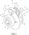
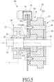
- the present invention is structurally formed of an output shaft 10, a transmission module 20, and at least one speed-up module 30, such that the transmission module 20 is acted upon by a power source to drive the output shaft 10 to generate an output and each speed step-up module 30 is operable step up a speed inputted to the transmission module 20.
- the output shaft 10 is arranged to extend through the transmission module 20 and each speed step-up module 30 one by one.
- the output shaft 10 comprises a shaft expansion section 15 on which the transmission module 20 is arranged.
- the transmission module 20 comprises a driving roller 21 that is operable to drive the output shaft 10 unidirectionally.
- the driving roller 21 can be a belt pulley and can be driven by the power source through a belt. Further, the driving roller 21 is mounted on the shaft expansion section 15 of the output shaft 10 by means of a one-way shaft assembly 22.
- the one-way shaft assembly 22 comprises a one-way bearing 221 and two bearings 222 that are respectively arranged on two opposite sides of the one-way bearing 221.
- the driving roller 21 is formed, in a center thereof, with a shaft compartment or bore 25 to receive disposition of the one-way shaft assembly 22 therein, so that the driving roller 21 may unidirectionally drive the output shaft 10 to move in a predetermined direction, while idling or load-free rotating in an opposite direction.
- the speed step-up module 30 that is fit over the output shaft 10 is collaboratively operating with the transmission module 20 and selectively drives the output shaft 10.
- Each speed step-up module 30 comprises a connecting gear 31, a planet speed-change wheel assembly 32, a speed step-up gear 38, and an arrestor assembly 40.
- the connecting gear 31 is rotatably mounted on the output shaft 10.
- the connecting gear 31 comprises an engaging portion 311, and the driving roller 21 of the transmission module 20 is formed in a center thereof with an engaging portion 28 for mutual engagement with each other, such that the connecting gear 31 is synchronously operable or rotatable with the driving roller 21.
- the connecting gear 31 is provided, on an outer circumference thereof, with a large-diameter toothed portion 312 for driving the planet speed-change wheel assembly 32.
- the planet speed-change wheel assembly 32 comprises at least one speed-change gear 33 that synchronously orbits around the connecting gear 31, wherein each speed-change gear 33 comprises a small-diameter toothed portion 331 in mating engagement with the large-diameter toothed portion 312 of the connecting gear 31 and a large-diameter toothed portion 332 of which a diameter is greater than a diameter of the small-diameter toothed portion 331.
- the speed step-up gear 38 is fixed to the output shaft 10, and a diameter of the speed step-up gear 38 is smaller than the diameter of the large-diameter toothed portion 332 of the speed-change gear 33, and the large-diameter toothed portion 332 of the speed-change gear 33 is in mating engagement with the speed step-up gear 38, in order to achieve an effect of driving the output shaft 10 with a stepped-up speed.
- the planet speed-change wheel assembly 32 may comprise two or more than two speed-change gears 33 that are sequentially in engagement with each other, and a terminal speed-change gear 33 is in mating engagement with the speed step-up gear 38 so as to achieve an effect of more greatly stepping up the speed.
- the speed-change gear 33 of the planet speed-change wheel assembly 32 is rotatably mounted to a wheel frame 35.
- the wheel frame 35 comprises at least two mounting pillars 352 each of which has two ends to each of which a frame plate 351 is mounted to receive the output shaft 10 to extend through a center thereof.
- Each speed-change gear 33 is rotatably mounted between the two frame plates 351, 353 by a wheel shaft 36, so that each speed-change gear 33 drives the wheel frame 35 to do orbiting motion and spinning motion about the output shaft 10.
- the arrestor assembly 40 is arranged on the planet speed-change wheel assembly 32 to selectively stop the orbiting motion of the speed-change gear 33 of the planet speed-change wheel assembly 32 relative to the output shaft 10.
- the arrestor assembly 40 comprises a disc plate 41 fixedly mounted to one side of the wheel frame 35 of the planet speed-change wheel assembly 32 and a stopping member 45 arranged on a circumference of the disc plate 41 to selectively stop rotation of the disc plate 41 so as to simultaneously stop the orbiting motion of the speed-change gear 33 of the planet speed-change wheel assembly 32 relative to the output shaft 10.
- the stopping member 45 can be a caliper, an electromagnetic device, and a brake pad.
- the transmission module 20 can be activated to drive the output shaft 10 to generate an output of an initial speed position, and an arresting operation of the arrestor assembly 40 may be used to make the speed step-up module 30 selectively step up an output speed of the output shaft 10, so as to thereby form a planetary speed-change mechanism.
- the arrestor assembly 40 of the speed step-up module 30 is not activated, and under such a condition, with the power source driving the driving roller 21 of the transmission module 20, the driving roller 21 drives directly, by means of the one-way shaft assembly 22, the output shaft 10 to rotate in synchronization therewith, while the driving roller 21 synchronously drives the connecting gear 31 of the speed step-up module 30 to rotate to have the connecting gear 31 acting on the speed-change gear 33 of the planet speed-change wheel assembly 32 that is in mating engagement therewith, making the speed-change gear 33 of the planet speed-change wheel assembly 32 not in interference with the speed step-up gear 38 mounted on the output shaft 10, whereby the output shaft 10 is set to provide an output of speed at the initial position.
- the arrestor assembly 40 of the speed step-up module 30 is activated to stop the orbiting motion of the speed-change gear 33 of the planet speed-change wheel assembly 32 by means of for example having the stopping member 45 of the arrestor assembly 40 tightly clamp the disc plate 41 to fixedly hold the wheel frame 35 of the speed step-up module 30 that is fixed to the disc plate 41 and simultaneously stop the orbiting motion of the speed-change gear 33 relative to the speed step-up gear 38.
- the connecting gear 31 of the speed step-up module 30 is coupled to the driving roller 21 of the transmission module 20, the connecting gear 31 synchronously drive the speed-change gear 33 in mating engagement therewith to do spinning motion and thus each speed-change gear 33 synchronously drive the speed step-up gear 38 in mating engagement therewith. Since the connecting gear 31 engages the small-diameter toothed portion 331 of the speed-change gear 33 by means of the large-diameter toothed portion 312 and the large-diameter toothed portion 332 of the speed-change gear 33 engages the speed step-up gear 38 that is of a relatively small diameter, the speed that the speed step-up gear 38 drives the output shaft 10 to output is increased relative to an input speed of the driving roller 21.
- the one-way shaft assembly 22 that includes the one-way bearing 221 is arranged between the output shaft 10 and the driving roller 21 of the transmission module 20, when the output shaft 10 is rotating at a speed higher than that of the driving roller 21, an effect of idling in an opposite direction achieved with the one-way shaft assembly 22 would prevent the output shaft 10 that is rotating at a relatively high speed from interfering with the driving roller 21 of a speed of the initial position, allowing the output shaft 10 to generate an output of speed that corresponds to a speed-up position.
- the present invention provides the one-way shaft assembly 22 to mount the driving roller 21 of the transmission module 20 on the output shaft 10 and also additionally provides the speed step-up module 30 that is mounted to the output shaft 10 to rotate in unison with the driving roller 21, and the speed step-up module 30 also comprises the planet speed-change wheel assembly 32 that is selectively stopped by means of the arrestor assembly 40, so that when a low speed is desired, the planet speed-change wheel assembly 32 of the speed step-up module 30 is set in an idling condition as being orbiting about the output shaft 10 to allow the power source to drive, by means of the driving roller 21, the output shaft 10 unidirectionally to generate a speed at the initial position, and when it is desired to step up the speed, the arrestor assembly 40 is activated to stop the orbiting motion of the planet speed-change wheel assembly 32 to allow the planet speed-change wheel assembly 32 to drive, by means of the speed-change gear 33, the output shaft 10 to achieve stepping up speed, and is also set in an idling
Landscapes
- Engineering & Computer Science (AREA)
- General Engineering & Computer Science (AREA)
- Mechanical Engineering (AREA)
- Structure Of Transmissions (AREA)
- Transmission Devices (AREA)
- Friction Gearing (AREA)
Applications Claiming Priority (1)
| Application Number | Priority Date | Filing Date | Title |
|---|---|---|---|
| TW109129396A TWI755041B (zh) | 2020-08-27 | 2020-08-27 | 周轉式變速機構 |
Publications (3)
| Publication Number | Publication Date |
|---|---|
| EP3971447A1 true EP3971447A1 (de) | 2022-03-23 |
| EP3971447C0 EP3971447C0 (de) | 2023-12-20 |
| EP3971447B1 EP3971447B1 (de) | 2023-12-20 |
Family
ID=77447750
Family Applications (1)
| Application Number | Title | Priority Date | Filing Date |
|---|---|---|---|
| EP21192502.9A Active EP3971447B1 (de) | 2020-08-27 | 2021-08-23 | Planetengeschwindigkeitsänderungsmechanismus |
Country Status (6)
| Country | Link |
|---|---|
| US (1) | US11480233B2 (de) |
| EP (1) | EP3971447B1 (de) |
| JP (2) | JP3234796U (de) |
| KR (1) | KR102669917B1 (de) |
| CN (2) | CN114110106B (de) |
| TW (1) | TWI755041B (de) |
Families Citing this family (2)
| Publication number | Priority date | Publication date | Assignee | Title |
|---|---|---|---|---|
| TWI755041B (zh) * | 2020-08-27 | 2022-02-11 | 姚立和 | 周轉式變速機構 |
| CN116576226B (zh) * | 2023-06-12 | 2026-04-28 | 特百佳动力科技股份有限公司 | 一种变速装置及车辆 |
Citations (5)
| Publication number | Priority date | Publication date | Assignee | Title |
|---|---|---|---|---|
| GB2044391A (en) * | 1979-03-23 | 1980-10-15 | Reliance Electric Co | Controlled start speed reducer |
| EP0301704A1 (de) * | 1987-07-13 | 1989-02-01 | Borg-Warner Automotive, Inc. | Zweigang-Drehstromgeneratorantrieb |
| US4878401A (en) * | 1988-09-02 | 1989-11-07 | Jackson Chung | Combination accessory drive and speed reducer |
| EP0591617A2 (de) * | 1992-10-08 | 1994-04-13 | Firma Carl Freudenberg | Schaltbarer Zweistufentrieb mit einer Bremse |
| US5328419A (en) * | 1992-04-10 | 1994-07-12 | Borg-Warner Automotive, Inc. | Two-speed alternator drive |
Family Cites Families (10)
| Publication number | Priority date | Publication date | Assignee | Title |
|---|---|---|---|---|
| US2269020A (en) * | 1942-01-06 | Variable speed power transmission | ||
| US2301072A (en) * | 1941-09-20 | 1942-11-03 | Bendix Aviat Corp | Supercharger control |
| US5139468A (en) * | 1991-11-08 | 1992-08-18 | Borg-Warner Automotive, Inc. | Two speed engine accessory drive with plastic planet gears |
| CN2477527Y (zh) * | 2000-01-13 | 2002-02-20 | 赵洪仁 | 用于自行车的行星式增速器 |
| HUP1400594A2 (en) * | 2014-12-16 | 2016-07-28 | Atakomb Kft | Gearbox |
| CN106594239A (zh) * | 2016-12-30 | 2017-04-26 | 孙乾 | 集成对称式电动轿车变速装置 |
| KR102478084B1 (ko) * | 2017-12-20 | 2022-12-15 | 현대자동차주식회사 | 크랭크축 풀리의 토크증대기구 |
| CN110043620A (zh) * | 2018-01-15 | 2019-07-23 | 怀化沃普环保科技有限公司 | 行星齿轮与轴固定连体式行星齿轮变速器 |
| TWI755041B (zh) * | 2020-08-27 | 2022-02-11 | 姚立和 | 周轉式變速機構 |
| TWM608330U (zh) * | 2020-08-27 | 2021-03-01 | 姚立和 | 周轉式變速機構 |
-
2020
- 2020-08-27 TW TW109129396A patent/TWI755041B/zh active
-
2021
- 2021-08-23 EP EP21192502.9A patent/EP3971447B1/de active Active
- 2021-08-23 US US17/408,492 patent/US11480233B2/en active Active
- 2021-08-24 CN CN202110977721.8A patent/CN114110106B/zh active Active
- 2021-08-24 CN CN202122007272.2U patent/CN217108055U/zh active Active
- 2021-08-25 JP JP2021003301U patent/JP3234796U/ja active Active
- 2021-08-25 KR KR1020210112122A patent/KR102669917B1/ko active Active
- 2021-08-25 JP JP2021137091A patent/JP7365714B2/ja active Active
Patent Citations (5)
| Publication number | Priority date | Publication date | Assignee | Title |
|---|---|---|---|---|
| GB2044391A (en) * | 1979-03-23 | 1980-10-15 | Reliance Electric Co | Controlled start speed reducer |
| EP0301704A1 (de) * | 1987-07-13 | 1989-02-01 | Borg-Warner Automotive, Inc. | Zweigang-Drehstromgeneratorantrieb |
| US4878401A (en) * | 1988-09-02 | 1989-11-07 | Jackson Chung | Combination accessory drive and speed reducer |
| US5328419A (en) * | 1992-04-10 | 1994-07-12 | Borg-Warner Automotive, Inc. | Two-speed alternator drive |
| EP0591617A2 (de) * | 1992-10-08 | 1994-04-13 | Firma Carl Freudenberg | Schaltbarer Zweistufentrieb mit einer Bremse |
Also Published As
| Publication number | Publication date |
|---|---|
| JP3234796U (ja) | 2021-11-04 |
| US11480233B2 (en) | 2022-10-25 |
| JP2022040064A (ja) | 2022-03-10 |
| US20220065335A1 (en) | 2022-03-03 |
| TW202208763A (zh) | 2022-03-01 |
| KR20220027782A (ko) | 2022-03-08 |
| CN217108055U (zh) | 2022-08-02 |
| KR102669917B1 (ko) | 2024-05-28 |
| TWI755041B (zh) | 2022-02-11 |
| JP7365714B2 (ja) | 2023-10-20 |
| EP3971447C0 (de) | 2023-12-20 |
| EP3971447B1 (de) | 2023-12-20 |
| CN114110106A (zh) | 2022-03-01 |
| CN114110106B (zh) | 2025-11-18 |
Similar Documents
| Publication | Publication Date | Title |
|---|---|---|
| CA2401474C (en) | Drive roller control for toric-drive transmission | |
| US11480233B2 (en) | Planetary speed-change mechanism | |
| CN102317649A (zh) | 无级变速器 | |
| US11300183B2 (en) | Structure of speed changer | |
| EP1999769B1 (de) | Verfahren und vorrichtung zur übertragung von drehbewegung | |
| KR20090040075A (ko) | 듀얼클러치 변속기용 클러치액츄에이터 | |
| EP4040014A1 (de) | Übertragungssystem zur übertragung einer geschwindigkeit und eines drehmoments eines motors auf eine radanordnung und verfahren zur übertragung einer geschwindigkeit und eines drehmoments eines motors auf eine radanordnung | |
| US20070155560A1 (en) | Linear actuator | |
| CN116292777B (zh) | 一种用于不同变速机构的自适应变速装置及变速器 | |
| US11988269B2 (en) | Three-stage speed-change mechanism | |
| CN212055702U (zh) | 行星离心式无级传动机构 | |
| CN118353207B (zh) | 一种可自动更变扭矩的电动机 | |
| CN102168744B (zh) | 双带式同步运动无级变速器 | |
| CN1388330A (zh) | 用磁力传递机械旋转运动的装置 | |
| CN208719184U (zh) | 一种离合机构以及离合器 | |
| KR20010015699A (ko) | 전기 기계 | |
| CN216045262U (zh) | 变刚性大行程离心动齿啮合链传动张紧装置 | |
| KR100637584B1 (ko) | 무단변속기 | |
| KR200285842Y1 (ko) | 무단 가변속 전동기 | |
| JP3079144B2 (ja) | 可変減速装置 | |
| KR200141554Y1 (ko) | 정,역회전 변환장치 | |
| KR100554543B1 (ko) | 전자제어 캘리퍼 브레이크용 전동장치 | |
| KR0136108Y1 (ko) | 감속장치 | |
| CN121162659A (zh) | 一种变速箱 | |
| RU2097626C1 (ru) | Лобовой вариатор |
Legal Events
| Date | Code | Title | Description |
|---|---|---|---|
| PUAI | Public reference made under article 153(3) epc to a published international application that has entered the european phase |
Free format text: ORIGINAL CODE: 0009012 |
|
| STAA | Information on the status of an ep patent application or granted ep patent |
Free format text: STATUS: THE APPLICATION HAS BEEN PUBLISHED |
|
| AK | Designated contracting states |
Kind code of ref document: A1 Designated state(s): AL AT BE BG CH CY CZ DE DK EE ES FI FR GB GR HR HU IE IS IT LI LT LU LV MC MK MT NL NO PL PT RO RS SE SI SK SM TR |
|
| STAA | Information on the status of an ep patent application or granted ep patent |
Free format text: STATUS: REQUEST FOR EXAMINATION WAS MADE |
|
| 17P | Request for examination filed |
Effective date: 20220712 |
|
| RBV | Designated contracting states (corrected) |
Designated state(s): AL AT BE BG CH CY CZ DE DK EE ES FI FR GB GR HR HU IE IS IT LI LT LU LV MC MK MT NL NO PL PT RO RS SE SI SK SM TR |
|
| STAA | Information on the status of an ep patent application or granted ep patent |
Free format text: STATUS: EXAMINATION IS IN PROGRESS |
|
| 17Q | First examination report despatched |
Effective date: 20230302 |
|
| GRAP | Despatch of communication of intention to grant a patent |
Free format text: ORIGINAL CODE: EPIDOSNIGR1 |
|
| STAA | Information on the status of an ep patent application or granted ep patent |
Free format text: STATUS: GRANT OF PATENT IS INTENDED |
|
| INTG | Intention to grant announced |
Effective date: 20230720 |
|
| GRAS | Grant fee paid |
Free format text: ORIGINAL CODE: EPIDOSNIGR3 |
|
| GRAA | (expected) grant |
Free format text: ORIGINAL CODE: 0009210 |
|
| STAA | Information on the status of an ep patent application or granted ep patent |
Free format text: STATUS: THE PATENT HAS BEEN GRANTED |
|
| AK | Designated contracting states |
Kind code of ref document: B1 Designated state(s): AL AT BE BG CH CY CZ DE DK EE ES FI FR GB GR HR HU IE IS IT LI LT LU LV MC MK MT NL NO PL PT RO RS SE SI SK SM TR |
|
| REG | Reference to a national code |
Ref country code: GB Ref legal event code: FG4D |
|
| REG | Reference to a national code |
Ref country code: DE Ref legal event code: R096 Ref document number: 602021007843 Country of ref document: DE |
|
| REG | Reference to a national code |
Ref country code: CH Ref legal event code: EP |
|
| REG | Reference to a national code |
Ref country code: IE Ref legal event code: FG4D |
|
| U01 | Request for unitary effect filed |
Effective date: 20240117 |
|
| U07 | Unitary effect registered |
Designated state(s): AT BE BG DE DK EE FI FR IT LT LU LV MT NL PT SE SI Effective date: 20240125 |
|
| PG25 | Lapsed in a contracting state [announced via postgrant information from national office to epo] |
Ref country code: GR Free format text: LAPSE BECAUSE OF FAILURE TO SUBMIT A TRANSLATION OF THE DESCRIPTION OR TO PAY THE FEE WITHIN THE PRESCRIBED TIME-LIMIT Effective date: 20240321 |
|
| PG25 | Lapsed in a contracting state [announced via postgrant information from national office to epo] |
Ref country code: ES Free format text: LAPSE BECAUSE OF FAILURE TO SUBMIT A TRANSLATION OF THE DESCRIPTION OR TO PAY THE FEE WITHIN THE PRESCRIBED TIME-LIMIT Effective date: 20231220 |
|
| PG25 | Lapsed in a contracting state [announced via postgrant information from national office to epo] |
Ref country code: GR Free format text: LAPSE BECAUSE OF FAILURE TO SUBMIT A TRANSLATION OF THE DESCRIPTION OR TO PAY THE FEE WITHIN THE PRESCRIBED TIME-LIMIT Effective date: 20240321 Ref country code: ES Free format text: LAPSE BECAUSE OF FAILURE TO SUBMIT A TRANSLATION OF THE DESCRIPTION OR TO PAY THE FEE WITHIN THE PRESCRIBED TIME-LIMIT Effective date: 20231220 |
|
| PG25 | Lapsed in a contracting state [announced via postgrant information from national office to epo] |
Ref country code: RS Free format text: LAPSE BECAUSE OF FAILURE TO SUBMIT A TRANSLATION OF THE DESCRIPTION OR TO PAY THE FEE WITHIN THE PRESCRIBED TIME-LIMIT Effective date: 20231220 Ref country code: NO Free format text: LAPSE BECAUSE OF FAILURE TO SUBMIT A TRANSLATION OF THE DESCRIPTION OR TO PAY THE FEE WITHIN THE PRESCRIBED TIME-LIMIT Effective date: 20240320 Ref country code: HR Free format text: LAPSE BECAUSE OF FAILURE TO SUBMIT A TRANSLATION OF THE DESCRIPTION OR TO PAY THE FEE WITHIN THE PRESCRIBED TIME-LIMIT Effective date: 20231220 |
|
| PG25 | Lapsed in a contracting state [announced via postgrant information from national office to epo] |
Ref country code: IS Free format text: LAPSE BECAUSE OF FAILURE TO SUBMIT A TRANSLATION OF THE DESCRIPTION OR TO PAY THE FEE WITHIN THE PRESCRIBED TIME-LIMIT Effective date: 20240420 |
|
| PG25 | Lapsed in a contracting state [announced via postgrant information from national office to epo] |
Ref country code: CZ Free format text: LAPSE BECAUSE OF FAILURE TO SUBMIT A TRANSLATION OF THE DESCRIPTION OR TO PAY THE FEE WITHIN THE PRESCRIBED TIME-LIMIT Effective date: 20231220 |
|
| PG25 | Lapsed in a contracting state [announced via postgrant information from national office to epo] |
Ref country code: SK Free format text: LAPSE BECAUSE OF FAILURE TO SUBMIT A TRANSLATION OF THE DESCRIPTION OR TO PAY THE FEE WITHIN THE PRESCRIBED TIME-LIMIT Effective date: 20231220 |
|
| PG25 | Lapsed in a contracting state [announced via postgrant information from national office to epo] |
Ref country code: SM Free format text: LAPSE BECAUSE OF FAILURE TO SUBMIT A TRANSLATION OF THE DESCRIPTION OR TO PAY THE FEE WITHIN THE PRESCRIBED TIME-LIMIT Effective date: 20231220 Ref country code: SK Free format text: LAPSE BECAUSE OF FAILURE TO SUBMIT A TRANSLATION OF THE DESCRIPTION OR TO PAY THE FEE WITHIN THE PRESCRIBED TIME-LIMIT Effective date: 20231220 Ref country code: RO Free format text: LAPSE BECAUSE OF FAILURE TO SUBMIT A TRANSLATION OF THE DESCRIPTION OR TO PAY THE FEE WITHIN THE PRESCRIBED TIME-LIMIT Effective date: 20231220 Ref country code: IS Free format text: LAPSE BECAUSE OF FAILURE TO SUBMIT A TRANSLATION OF THE DESCRIPTION OR TO PAY THE FEE WITHIN THE PRESCRIBED TIME-LIMIT Effective date: 20240420 Ref country code: CZ Free format text: LAPSE BECAUSE OF FAILURE TO SUBMIT A TRANSLATION OF THE DESCRIPTION OR TO PAY THE FEE WITHIN THE PRESCRIBED TIME-LIMIT Effective date: 20231220 |
|
| PG25 | Lapsed in a contracting state [announced via postgrant information from national office to epo] |
Ref country code: PL Free format text: LAPSE BECAUSE OF FAILURE TO SUBMIT A TRANSLATION OF THE DESCRIPTION OR TO PAY THE FEE WITHIN THE PRESCRIBED TIME-LIMIT Effective date: 20231220 |
|
| PG25 | Lapsed in a contracting state [announced via postgrant information from national office to epo] |
Ref country code: PL Free format text: LAPSE BECAUSE OF FAILURE TO SUBMIT A TRANSLATION OF THE DESCRIPTION OR TO PAY THE FEE WITHIN THE PRESCRIBED TIME-LIMIT Effective date: 20231220 |
|
| U20 | Renewal fee for the european patent with unitary effect paid |
Year of fee payment: 4 Effective date: 20240813 |
|
| REG | Reference to a national code |
Ref country code: DE Ref legal event code: R097 Ref document number: 602021007843 Country of ref document: DE |
|
| PLBE | No opposition filed within time limit |
Free format text: ORIGINAL CODE: 0009261 |
|
| STAA | Information on the status of an ep patent application or granted ep patent |
Free format text: STATUS: NO OPPOSITION FILED WITHIN TIME LIMIT |
|
| 26N | No opposition filed |
Effective date: 20240923 |
|
| REG | Reference to a national code |
Ref country code: CH Ref legal event code: PL |
|
| PG25 | Lapsed in a contracting state [announced via postgrant information from national office to epo] |
Ref country code: CH Free format text: LAPSE BECAUSE OF NON-PAYMENT OF DUE FEES Effective date: 20240831 Ref country code: MC Free format text: LAPSE BECAUSE OF FAILURE TO SUBMIT A TRANSLATION OF THE DESCRIPTION OR TO PAY THE FEE WITHIN THE PRESCRIBED TIME-LIMIT Effective date: 20231220 |
|
| PG25 | Lapsed in a contracting state [announced via postgrant information from national office to epo] |
Ref country code: IE Free format text: LAPSE BECAUSE OF NON-PAYMENT OF DUE FEES Effective date: 20240823 |
|
| PG25 | Lapsed in a contracting state [announced via postgrant information from national office to epo] |
Ref country code: CY Free format text: LAPSE BECAUSE OF FAILURE TO SUBMIT A TRANSLATION OF THE DESCRIPTION OR TO PAY THE FEE WITHIN THE PRESCRIBED TIME-LIMIT; INVALID AB INITIO Effective date: 20210823 |
|
| PG25 | Lapsed in a contracting state [announced via postgrant information from national office to epo] |
Ref country code: HU Free format text: LAPSE BECAUSE OF FAILURE TO SUBMIT A TRANSLATION OF THE DESCRIPTION OR TO PAY THE FEE WITHIN THE PRESCRIBED TIME-LIMIT; INVALID AB INITIO Effective date: 20210823 |
|
| U21 | Renewal fee for the european patent with unitary effect paid with additional fee |
Year of fee payment: 5 Effective date: 20260211 |
|
| PGFP | Annual fee paid to national office [announced via postgrant information from national office to epo] |
Ref country code: GB Payment date: 20260212 Year of fee payment: 5 |