EP3971408A1 - Verfahren zur verbesserung der verbrennungseigenschaften von brennstoff - Google Patents
Verfahren zur verbesserung der verbrennungseigenschaften von brennstoff Download PDFInfo
- Publication number
- EP3971408A1 EP3971408A1 EP20196404.6A EP20196404A EP3971408A1 EP 3971408 A1 EP3971408 A1 EP 3971408A1 EP 20196404 A EP20196404 A EP 20196404A EP 3971408 A1 EP3971408 A1 EP 3971408A1
- Authority
- EP
- European Patent Office
- Prior art keywords
- frequency
- fuel
- range
- limit
- ghz
- Prior art date
- Legal status (The legal status is an assumption and is not a legal conclusion. Google has not performed a legal analysis and makes no representation as to the accuracy of the status listed.)
- Withdrawn
Links
Images


Classifications
-
- F—MECHANICAL ENGINEERING; LIGHTING; HEATING; WEAPONS; BLASTING
- F02—COMBUSTION ENGINES; HOT-GAS OR COMBUSTION-PRODUCT ENGINE PLANTS
- F02M—SUPPLYING COMBUSTION ENGINES IN GENERAL WITH COMBUSTIBLE MIXTURES OR CONSTITUENTS THEREOF
- F02M27/00—Apparatus for treating combustion-air, fuel, or fuel-air mixture, by catalysts, electric means, magnetism, rays, sound waves, or the like
- F02M27/04—Apparatus for treating combustion-air, fuel, or fuel-air mixture, by catalysts, electric means, magnetism, rays, sound waves, or the like by electric means, ionisation, polarisation or magnetism
- F02M2027/047—Apparatus for treating combustion-air, fuel, or fuel-air mixture, by catalysts, electric means, magnetism, rays, sound waves, or the like by electric means, ionisation, polarisation or magnetism with a pulsating magnetic field
Definitions
- the present disclosure relates to a method of improving combustion properties of fuel used to power combustion engines.
- Improving combustion properties of fuel by action of a permanent magnetic field or an electromagnetic field on a flowing liquid fuel is known in the art. It is believed that the magnetic field reduces the surface tension of the flowing fuel and separates and/or homogenizes the molecules of the fuel. Thus, when the fuel treated by the magnetic field is sprayed or atomized in a combustion chamber of a combustion engine, the fuel may be separated into smaller droplets, so that a significantly improved fuel utilization may be achieved.
- the method may be particularly relevant for denser fuels, such as diesel used in larger vehicles, such as trucks, and in marine vehicles.
- EP0652362A1 describes a method for reducing the consumption of fossil fuels flowing through a magnetically permeable fuel feed line by means of a magnetic field which is applied to the fuel by an external magnetization means.
- an alternating magnetic field is provided by a coil through which a current of periodically changing amplitude and frequency is running. It is mentioned that the frequency of the current is preferably changed continuously within a frequency range between two frequency limit values. Such a continuous change in frequency is mentioned as being preferred due to the assumption that a range of frequencies will contain frequencies that are optimal for the flow velocity of the fuel. This is said to eliminate the need for measuring the fuel flow velocity in real time and adjusting the frequency to the frequency optimal for the fuel flow velocity.
- the method uses a power supply providing a current to the solenoid.
- the current provided by the power supply has a voltage having a periodically varying voltage (when measured at the output of the power supply), i.e. the voltage has a frequency.
- the voltage may be positive (+), e.g. continuously positive (+), negative (-), e.g. continuously negative (-), or fluctuate between positive and negative voltage (+/-), i.e. the current may be running in one direction or it may reverse in direction periodically.
- the varying voltage may (as a function of time) have any shape which has a waveform that repeats over time (frequency), such as a sinus curve (conventional alternating current), a sawtooth, a square wave, a triangular shape, an amorphous (repetitive) curve, or a combination thereof, all of which may have the current running only in one direction (DC, +/-) or have reversal of the current direction.
- the frequency of the voltage should be understood as the number of times the waveform of the voltage repeats over time.
- the current provided by the power supply is provided as an alternating current (AC), wherein the frequency of the voltage is the frequency of the alternating current.
- AC alternating current
- the periodically varying voltage has a maximum and a minimum that are both positive, e.g. the current may be a pulsating direct current wherein the frequency of the voltage is the frequency of the pulsating direct current.
- the periodically varying voltage has a maximum voltage and a minimum voltage that are both negative, e.g. the current may be a pulsating negative direct current, wherein the frequency of the voltage is the frequency of the pulsating negative direct current.
- the varying voltage has a positive maximum voltage and a negative minimum voltage, e.g. the current may be an alternating current (AC).
- the power supply may be any power supply, which may be configured to provide a current periodically varying in voltage according to a waveform and thereby having a frequency. It is well-known in the art how to configure a power supply, so that it may provide such a current.
- the method employs a sweep cycle that is defined by a first limit frequency and a last limit frequency, and the frequency of the voltage is varied over the sweep cycle.
- the first limit frequency may be lower than the last limit frequency so that the frequency of the voltage is increased over the sweep cycle, or first limit frequency may be higher than the last limit frequency so that the frequency of the voltage is decreased over the sweep cycle.
- the method has sweep cycles where the first limit frequency is lower than the last limit frequency combined with sweep cycles where the first limit frequency is higher than the last limit frequency.
- the sweep cycle may include any frequency between the first limit frequency and the last limit frequency. Changing the frequency may involve gradually ramping up or down the frequency between the two limit frequencies, the gradual ramping up or down being continuous, in steps or a combination thereof.
- the frequencies between the first limit frequency and the last limit frequency may be any number of distinct frequency values, or the frequencies may be represented by a smooth change in frequencies from the first limit frequency to the last limit frequency.
- the frequencies between the first limit frequency and the last limit frequency may be divided into any number of frequency intervals, e.g. equidistant frequency intervals.
- the frequency may be a frequency between the two limit frequencies.
- the change between the first and the last limit frequency may also occur immediately between the two limit frequencies.
- the change includes frequencies between the two limit frequencies.
- the sweep cycle may, within the range of the first and the last limit frequencies, have ranges of frequencies which are not included in the sweep cycle.
- the sweep may exclude single, or multiple discrete frequency values between 250 Hz to 10 GHz, such as frequencies in the range of 4000 to 4500 Hz.
- the frequency of the voltage is, at any given time, a frequency in the range of the two limit frequencies or a frequency in the range of the two limit frequencies, which is not an excluded frequency.
- the change in frequency over time may take any shape, such as a linear ramp, an s-shaped ramp, an exponential ramp, a ramp with different linear slopes, or a combination thereof.
- the change in frequencies is considered to involve all frequencies between the first limit frequency and the last limit frequency (which are not excluded frequencies).
- the actual frequencies involved in a smooth change will depend on the device employed to implement. The skilled person will know the actual frequencies available and the actual smoothness in the change depending on the type of device employed. A smooth change in frequencies may follow any curve describing the increase.
- the change may follow a linear increase or decrease, it may be an exponential increase or decrease, or it may be a step-wise increase or decrease or a combination thereof.
- the first limit frequency is lower than the last limit frequency, and the frequency of the voltage is increased linearly to the last limit frequency followed by a quick, e.g. instantaneous, decrease back to the first limit frequency before staring the next, in particular the next identical, sweep cycle.
- This alteration of the frequency of the voltage in this embodiment is referred to as a sawtooth-like curve.
- the current is provided to the solenoid as an AC current, e.g. an AC current with a voltage varying in frequency according to the sweep cycle, such a sweep cycle with a first limit frequency and a last limit frequency that are in the range of 250 Hz to 10 GHz and are separated by at least 5000 Hz.
- the sweep cycle has a duration in the range of 0.01 s to 1 s.
- the method may employ any number of sweep cycles, but the method is preferably performed continuously. For example, a continuous flow of fuel may be applied through the magnetically permeable fuel conduit, while the method is performed as long as the fuel is flowing through the magnetically permeable fuel conduit.
- the method includes at least 10, e.g. at least 100, at least 1000, or at least 10,000 sweep cycles.
- the sweep cycle may also be represented with a frequency, and thus, the sweep can be considered to occur (is repeated) with a frequency in the range of 1 to 100 times per second, such as once per second, preferably 1 to 20 times per second, more preferably 4 to 16 times per second, even more preferably 10 to 12 times per second, most preferably 11 sweeps per second.
- the sweep is repeated by initiating a new sweep cycle immediately following a last completed sweep cycle, initiating a sweep cycle a period of time after the last completed sweep cycle (such as a few milliseconds after), or a combination thereof.
- the sweep cycle is repeated immediately following the last completed sweep cycle.
- the limit frequencies may be selected freely for repeated sweep cycles, and the limit frequencies may be different in different sweep cycles.
- the frequency is increased from the first limit frequency (ramped up) to the last frequency and then decreased immediately to the first frequency, i.e. in a single step change.
- the frequency is decreased (ramped down) from the last limit frequency to the first frequency and then increased immediately to the last limit frequency.
- the changes in frequency over time may be said to follow a sawtooth-like curve.
- the ramping up or down is preferably linear.
- Varying the charge of the voltage (+/-) i.e. reversing the current
- This in combination with the change in frequency of the voltage makes the magnetic flux level of the electromagnetic field vary over time relative to one or more directions (axes).
- the method of the present invention generates a magnetic flux, which varies at least in an axial direction relative to the solenoid, and even more preferably at least two spatial directions, such as a radial direction and an axial direction relative to the solenoid, or two radial directions and an axial direction relative to the solenoid.
- smaller molecules e.g. water
- larger compounds such as the saturated hydrocarbons and aromatic hydrocarbons present in fuel
- react to electromagnetic fields generated by currents having voltages with higher frequencies e.g. 250 Hz to 10000 Hz and 0.5 to 10 GHz.
- broad ranges of higher frequencies may be needed to cover the many different sizes of compounds that are usually present in fuel.
- one of the limit frequencies is in the range of 0.1 GHz to 1 GHz and the other limit frequency is in the range of 1 GHz to 10 GHz.
- the limit frequencies may define a range of 0.5 GHz to 5 GHz.
- the first and the last limit frequency is in the range of 0.1 GHz to 10 GHz and the difference between the first and the last limit frequency is at least 0.1 GHz.
- one of the limit frequencies is in the range of 250 Hz to 2500 Hz and the other limit frequency is in the range of 4000 Hz to 10000 Hz. In yet another embodiment, one of the limit frequencies is in the range of 250 Hz to 350 Hz and the other limit frequency is in the range of 8000 Hz to 10000 Hz. In yet another embodiment, the first limit frequency is 300 Hz and the last limit frequency is 9000 Hz.
- the one of the limit frequencies is in the range of 250 Hz to 350 Hz and the other limit frequency is in the range of 8000 Hz to 10000 Hz, and the sweep cycle has a duration in the range of 0.05 s to 1 s.
- one of the limit frequencies is in the range of 250 Hz to 350 Hz and the other limit frequency is in the range of 8000 Hz to 10000 Hz
- the sweep cycle has a duration in the range of 0.05 s to 1 s, and the change in frequency follows a sawtooth-like curve.
- one of the limit frequencies is in the range of 0.1 GHz to 1 GHz and the other limit frequency is in the range of 1 GHz to 10 GHz, the difference between the limit frequencies being at least 0.1 GHz, the sweep cycle has a duration in the range of 0.05 s to 1 s, and the change in frequency follows a sawtooth-like curve.
- one of the limit frequencies is in the range of 250 Hz to 350 Hz and the other limit frequency is in the range of 8000 Hz to 10000 Hz
- the sweep cycle has a duration in the range of 0.05 s to 1 s
- the change in frequency follows a sawtooth-like curve and the current is an alternating current, the frequency of the alternating current being the frequency of the voltage.
- the above limit frequencies may be adjusted to suit a particular type of fuel, i.e. a particular fuel composition, such that a greater improvement in fuel combustion properties may be observed.
- Another advantage of the invention is that it may decrease the heterogeneity of molecule weight of fuel. This effect may decrease particles created by combustion of the fuel (particles present in the exhaust). Without being bound by theory, the inventors believe that larger alkanes present in the fuel (e.g. alkanes with 25 carbon atoms or above) will acquire a momentum in a varying electromagnetic field, which can lead to breakage of the alkanes into smaller compounds that are more combustible.
- the heterogeneity of the fuel before and after treatment with the method of the present disclosure may be assessed using gas chromatography mass spectrometry, but other analytical methods are equally relevant. The skilled person knows how to carry out such analyses.
- the method of the present disclosure may preferably be used to reduce the number of particles produced by engines of larger vehicles, such as trucks, boats, ships and large industrial machinery. Such engines often run on diesel fuel or fuel oil and may be a considerable source of polluting particles and a may produce many more polluting particles than e.g. an engine running on petrol such as an engine in a car.
- the fuel should be treated according to the method presented herewith before combustion in an engine to achieve the benefits of the method.
- the method may not improve the combustion properties of fuel that has already been combusted.
- fuel should be understood as hydrocarbon containing fuels, which have on average at least 6 carbon atoms per hydrocarbon compound.
- the fuel may be a product of petroleum distillation, such as jet fuel, petrol/gasoline, diesel, or fuel oil, or it may be a biofuel, such as biodiesel.
- the fuel is liquid when treated and even more preferably it is a viscous fuel (at room temperature) such as diesel or fuel oil.
- the fuel may not need to be liquid at room temperature, i.e. the fuel may need to be heated to become liquid.
- the composition of the fuel used for the method of the present disclosure may comprise many different hydrocarbons.
- diesel fuel is a mixture of hydrocarbons and is typically composed of about 75 % saturated hydrocarbons, e.g. different types of paraffins, and 25 % aromatic hydrocarbons, e.g. napthalenes and alkylbenzenes.
- saturated hydrocarbons and/or aromatic hydrocarbons are charged by the method of the present disclosure, leading to improved fuel combustion properties.
- intra-molecular interactions could be affected by the method of the present disclosure, evening out tension and/or changing intra- molecular sticking, which in turn improves dispersion of the fuel in the combustion chamber.
- the inventors believe that the change in flux density over time may have a lower threshold at which below the method of the present disclosure has no or only infinitesimal influence on fuel combustion properties. Without being bound by theory, the inventors believe that above a certain suitable threshold of change in magnetic flux density over time, molecules present in the fuel are charged and/or Van der Waals forces of the molecules present in the fuel are affected. The change in flux density over time may be adjusted/increased to suit the particular fuel, such that an effect will be observed. Without being bound by theory, the inventors believe that the change in magnetic flux density over time may have an upper threshold limit and increasing the change in flux density beyond this threshold limit has no additional or only an infinitesimal additional effect on the combustion properties of the fuel.
- the electromagnetic field strength may be increased by increasing the numbers of electrical conductor turns around the conduit. Adjustment of an electromagnetic field strength provided by an electrical conductor, solenoid or coil is well-known in the art.
- the method of the present disclosure provides a peak magnetic flux density of at least 0.1 millitesla (mT), such as at least 0.5 mT, 1 mT, 1.5 mT, 2 mT, 2.5 mT, 3 mT, 3.5 mT, 4 mT, 4.5 mT, 5 mT, 5.5 mT, 6 mT, or 6.5 mT.
- the magnetic flux density is measured with a fluxgate magnetometer 5 cm from an axial end of the solenoid.
- the peak magnetic flux density should be understood as the largest measured flux density in any spatial direction over at least a period of 10 seconds. E.g.
- the peak flux density is 150 mT.
- the method of the present disclosure provides an electromagnetic field with a flux density that changes in level over time relative to a given direction, the flux density will have local maximum and minimum values over time. The difference in flux density between a local maximum and the local minimum immediately following the local maximum should be understood as a peak-to-peak flux density.
- the method of the present invention provides an electromagnetic field, which contain a peak-to-peak flux density of at least 400 mT, such as at least 600 mT, 800 mT, 1000 mT, 1200 mT, 1400 mT, 1600 mT, or 1800 mT.
- the inventors also contemplate that a minimum level of change in the direction of the electromagnetic field over time for a given direction relative to the solenoid may be required for the method of the present disclosure to have an effect on fuel combustion properties.
- a certain level of pulse intensity of the electromagnetic field may need to be reached for the method of the present disclosure to have an effect on fuel combustion properties.
- the change in the level of flux density over time for a given direction such as 2 mT over 200 milliseconds (ms) for the axial direction relative to the solenoid, should be understood as the pulse intensity for that direction.
- the solenoid and the power supply are configured for providing, for at least one direction, a pulse intensity of at least 5 mT/s, such as at least 10, 15, 20, 22, 23, or 24 mT/s.
- a pulse intensity of at least 5 mT/s such as at least 10, 15, 20, 22, 23, or 24 mT/s.
- One of the directions is preferably the axial direction of the solenoid.
- the solenoid and the power supply are configured for providing an electromagnetic field which has, at least for one direction, a pulse intensity of at least 5 mT/s and contains peak-to-peak flux densities of at least 400 mT.
- One of the directions is preferably the axial direction relative to the solenoid.
- the average voltage provided by the power supply is in the range of 34 V to 46 V, preferably in the range of 38 V to 44 V, more preferably 42 V.
- the fuel conduit provides a fluid connection between a fuel tank and a combustion engine and may range from a few centimeters in length to several meters in length.
- the electrical conductor is wound around the fuel conduit less than 10 m of fuel conduit away from a combustion chamber, such as in the range of 1 m to 5 m of fuel conduit, such as in the range of 2 m to 3 m of fuel conduit away from a combustion chamber.
- a particularly noticeable effect of the electrical conductor may be observed when the conductor is wound around a fuel conduit at the position of the fuel conduit which is immediately adjacent to a combustion chamber of the engine. In this way, fuel treated by the method of the present disclosure may be injected into the combustion chamber of the engine immediately after treatment of the fuel.
- the electrical conductor is wound around a fuel conduit, which fuel conduit recirculates fuel.
- the fuel may be recirculated in the conduit and subjected to the method of the present invention several times before being injected into the fuel chamber.
- Such recirculation may be present in engines running on diesel or fuel oil.
- conduit should be understood as any conduit suitable for containing a fuel and which allows a flow of fuel.
- the conduit may be a pipe, a tube, or an intermediate container (such as a tank) wherefrom the fuel may flow from to a combustion chamber of an engine.
- any magnetically permeable material may be used for the conduit.
- a magnetically permeable material are diamagnetic materials, such as diamagnetic plastics, metals, or other materials. Non-magnetic steel may also be used.
- Any electrical conductor may be used, such as a metal conductor, such as a conductor of made of cobber, silver, gold, iron or alloys thereof.
- solenoid should be understood as an electrical conductor wound into a helix. Solenoid may be used interchangeably with coil.
- Fig. 1 shows an exemplary embodiment of how an electromagnetic field generator system suitable for carrying out the method of the present disclosure may be configured.
- the electromagnetic field generator system 1 comprises a fuel conduit 2, which has an inlet 4 into which fuel may flow.
- the arrows indicate the flow direction of the fuel.
- the fuel is subjected to an electromagnetic field produced by providing an alternating current from the power supply 6 connected to the conductor 8 arranged externally to the fuel conduit 2.
- the power supply 6 is connected by electrical wires 10 to the at least one conductor 8 at each end of the conductor 8 in an electrical circuit.
- the conductor 8 is wound around the fuel conduit 2 creating a solenoid.
- the electromagnetic field will easily pass the wall of the fuel conduit and penetrate the fuel flowing inside the pipe.
- the power supply 6 is configured to provide an alternating current, which has a voltage with a frequency which sweeps between a first limit frequency and a last limit frequency, wherein the first limit frequency is 300 Hz and the second limit frequency is 9 kHz. The frequency sweeps eleven times per second, and the output voltage of the power supply 6 is 42 V.
- Fig. 3 shows a schematic example of how the voltage outputted by the power supply may vary over time and how it may be regulated.
- panel A) shows the frequency of the voltage on the Y axis as a function of time on the X axis, which frequency follows a sawtooth-like curve
- panel B) shows the waveform of an alternating current 11, wherein the voltage of the alternating current 11 is shown on the Y axis as a function of time on the X axis, wherein a single repeat of the waveform is completed in a period 15,
- panel C) illustrates panel A) combined with panel B), wherein the voltage is shown on the Y axis as a function of time on the X axis.
- the frequency of the voltage 12 is increased from a first limit frequency 12a to a last limit frequency 12b and then immediately returned to the first limit frequency 12a over a period 14. This cycle is continuously repeated, however, in the example only two cycles are shown.
- the frequency of the voltage is the frequency of the alternating current 11, i.e. the frequency of the alternating current is altered according to the curve in panel A), it results in a varying alternating current 13.
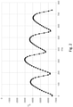
- a fluxgate magnetometer was arranged 5 cm in an axial direction from an inlet of the electromagnetic field generator system according to fig. 1 .
- the flux density was measured at an axial direction relative to the electromagnetic field generator system at a sample rate of 128Hz.
- Fig. 2 shows about 750 ms of this measurement, wherein the flux density in microtesla is shown on the Y axis as a function of time in milliseconds on the X axis.
Landscapes
- Engineering & Computer Science (AREA)
- Chemical & Material Sciences (AREA)
- Chemical Kinetics & Catalysis (AREA)
- Combustion & Propulsion (AREA)
- Mechanical Engineering (AREA)
- General Engineering & Computer Science (AREA)
- Feeding And Controlling Fuel (AREA)
Priority Applications (1)
| Application Number | Priority Date | Filing Date | Title |
|---|---|---|---|
| EP20196404.6A EP3971408A1 (de) | 2020-09-16 | 2020-09-16 | Verfahren zur verbesserung der verbrennungseigenschaften von brennstoff |
Applications Claiming Priority (1)
| Application Number | Priority Date | Filing Date | Title |
|---|---|---|---|
| EP20196404.6A EP3971408A1 (de) | 2020-09-16 | 2020-09-16 | Verfahren zur verbesserung der verbrennungseigenschaften von brennstoff |
Publications (1)
| Publication Number | Publication Date |
|---|---|
| EP3971408A1 true EP3971408A1 (de) | 2022-03-23 |
Family
ID=72521509
Family Applications (1)
| Application Number | Title | Priority Date | Filing Date |
|---|---|---|---|
| EP20196404.6A Withdrawn EP3971408A1 (de) | 2020-09-16 | 2020-09-16 | Verfahren zur verbesserung der verbrennungseigenschaften von brennstoff |
Country Status (1)
| Country | Link |
|---|---|
| EP (1) | EP3971408A1 (de) |
Citations (6)
| Publication number | Priority date | Publication date | Assignee | Title |
|---|---|---|---|---|
| EP0652362A1 (de) | 1993-10-21 | 1995-05-10 | Hartmut Dipl.-Ing. Schulte | Verfahren und Vorrichtung zur Verbrauchsminderung von fliessfähigen fossilen Brennstoffen |
| EP0894969A2 (de) * | 1997-07-30 | 1999-02-03 | Reika Elektronik Karin Walch | Vorrichtung zur Behandlung von flüssigen oder gasförmigen Brennstoffen |
| WO2002075144A1 (en) * | 2001-03-16 | 2002-09-26 | Eric Norman Ongley | Fuel saving device |
| WO2005108304A1 (en) * | 2004-05-12 | 2005-11-17 | Mikhnevich Vladimir V | Method and apparatus for liquid treatment |
| CN201671729U (zh) * | 2010-05-14 | 2010-12-15 | 何军 | 变频脉冲式发动机节油器 |
| US20190186435A1 (en) * | 2017-12-20 | 2019-06-20 | Plasma Igniter, LLC | Fuel Injection Using a Dielectric of a Resonator |
-
2020
- 2020-09-16 EP EP20196404.6A patent/EP3971408A1/de not_active Withdrawn
Patent Citations (6)
| Publication number | Priority date | Publication date | Assignee | Title |
|---|---|---|---|---|
| EP0652362A1 (de) | 1993-10-21 | 1995-05-10 | Hartmut Dipl.-Ing. Schulte | Verfahren und Vorrichtung zur Verbrauchsminderung von fliessfähigen fossilen Brennstoffen |
| EP0894969A2 (de) * | 1997-07-30 | 1999-02-03 | Reika Elektronik Karin Walch | Vorrichtung zur Behandlung von flüssigen oder gasförmigen Brennstoffen |
| WO2002075144A1 (en) * | 2001-03-16 | 2002-09-26 | Eric Norman Ongley | Fuel saving device |
| WO2005108304A1 (en) * | 2004-05-12 | 2005-11-17 | Mikhnevich Vladimir V | Method and apparatus for liquid treatment |
| CN201671729U (zh) * | 2010-05-14 | 2010-12-15 | 何军 | 变频脉冲式发动机节油器 |
| US20190186435A1 (en) * | 2017-12-20 | 2019-06-20 | Plasma Igniter, LLC | Fuel Injection Using a Dielectric of a Resonator |
Similar Documents
| Publication | Publication Date | Title |
|---|---|---|
| US20110248019A1 (en) | Method for treating hydrocarbon fluids using pulsating electromagnetic wave in combination with induction heating | |
| EP3971408A1 (de) | Verfahren zur verbesserung der verbrennungseigenschaften von brennstoff | |
| AU2017203043B2 (en) | Method and apparatus for indirect magnetic treatment of fluids and gases | |
| RU2562505C2 (ru) | Способ повышения эффективности сгорания углеводородного топлива | |
| CN106488968A (zh) | 藉由改进装置提供最大化触发磁性效应以处理包含氢及碳氢化合物之液体及气态物质 | |
| Bhurat et al. | Magnetization of diesel fuel for compression ignition engine to enhance efficiency and emissions | |
| EP0652362A1 (de) | Verfahren und Vorrichtung zur Verbrauchsminderung von fliessfähigen fossilen Brennstoffen | |
| CN101713355B (zh) | 一种实现节能减排的装置及方法 | |
| WO2009104070A2 (en) | Method and apparatus for mixing water or steam into liquid or gaseous hydrocarbons by electrochemical treatment | |
| US5620570A (en) | Method of manufacturing hydrous oil | |
| RU140192U1 (ru) | Устройство для электромагнитной модификации углеводородов на частотах ядерного магнитного резонанса | |
| Nufus et al. | The effect of electro magnetic field intensity to biodiesel characteristics | |
| Chandrasekaran et al. | Influence on performance and emission characteristics of diesel engine by introducing medium strength magnetic field in fuel and air lines | |
| RU2613504C2 (ru) | Способ обработки жидких сред короткими электромагнитными импульсами низкой частоты | |
| RU2568273C1 (ru) | Способ электромагнитной модификации жидких энергоносителей и устройство для его реализации | |
| Patel et al. | Performance and emission analysis of single cylinder diesel engine under the influence of magnetic fuel energizer | |
| Elamin et al. | Effect of magnetic field on some physical characteristics and cetane number of diesel fuel | |
| JP2009516115A (ja) | 内燃機関用燃料強化システム | |
| US6482318B1 (en) | Method and device for the treatment of fluids | |
| Al-Dossary | The effect of magnetic field on combustion and emissions | |
| EA007625B1 (ru) | Нефтяное топливо с наночастицами и способ его приготовления | |
| CN201925054U (zh) | 一种船舶节能减排装置 | |
| Nufus et al. | Study Of Diesel Engine Performance On The Electromagnetic Effect Of Biodiesel (Waste Cooking Oil) | |
| DE4309396A1 (de) | Gerät zur Steigerung des Brennwertes einer aus Öl oder Diesel- oder Benzinkraftstoffen bestehenden Flüssigkeit | |
| CN103982339A (zh) | 一种提高燃油效率的装置及方法 |
Legal Events
| Date | Code | Title | Description |
|---|---|---|---|
| PUAI | Public reference made under article 153(3) epc to a published international application that has entered the european phase |
Free format text: ORIGINAL CODE: 0009012 |
|
| STAA | Information on the status of an ep patent application or granted ep patent |
Free format text: STATUS: THE APPLICATION HAS BEEN PUBLISHED |
|
| AK | Designated contracting states |
Kind code of ref document: A1 Designated state(s): AL AT BE BG CH CY CZ DE DK EE ES FI FR GB GR HR HU IE IS IT LI LT LU LV MC MK MT NL NO PL PT RO RS SE SI SK SM TR |
|
| STAA | Information on the status of an ep patent application or granted ep patent |
Free format text: STATUS: THE APPLICATION IS DEEMED TO BE WITHDRAWN |
|
| 18D | Application deemed to be withdrawn |
Effective date: 20220924 |