EP3970567A1 - Seat - Google Patents
Seat Download PDFInfo
- Publication number
- EP3970567A1 EP3970567A1 EP20847085.6A EP20847085A EP3970567A1 EP 3970567 A1 EP3970567 A1 EP 3970567A1 EP 20847085 A EP20847085 A EP 20847085A EP 3970567 A1 EP3970567 A1 EP 3970567A1
- Authority
- EP
- European Patent Office
- Prior art keywords
- inward
- pad
- holding member
- suspending
- suspending portion
- Prior art date
- Legal status (The legal status is an assumption and is not a legal conclusion. Google has not performed a legal analysis and makes no representation as to the accuracy of the status listed.)
- Withdrawn
Links
- 230000003014 reinforcing effect Effects 0.000 claims description 23
- 239000002184 metal Substances 0.000 claims description 12
- 239000007787 solid Substances 0.000 description 6
- 239000000463 material Substances 0.000 description 5
- 239000011347 resin Substances 0.000 description 5
- 229920005989 resin Polymers 0.000 description 5
- 238000000034 method Methods 0.000 description 4
- 238000009958 sewing Methods 0.000 description 4
- 230000004048 modification Effects 0.000 description 3
- 238000012986 modification Methods 0.000 description 3
- 210000001217 buttock Anatomy 0.000 description 2
- 239000010985 leather Substances 0.000 description 2
- 230000037303 wrinkles Effects 0.000 description 2
- JOYRKODLDBILNP-UHFFFAOYSA-N Ethyl urethane Chemical compound CCOC(N)=O JOYRKODLDBILNP-UHFFFAOYSA-N 0.000 description 1
- 230000000694 effects Effects 0.000 description 1
- 239000004744 fabric Substances 0.000 description 1
- 238000005187 foaming Methods 0.000 description 1
- 230000001788 irregular Effects 0.000 description 1
- 239000010410 layer Substances 0.000 description 1
- 239000002649 leather substitute Substances 0.000 description 1
- 238000000465 moulding Methods 0.000 description 1
- 239000004745 nonwoven fabric Substances 0.000 description 1
- 230000000149 penetrating effect Effects 0.000 description 1
- 230000002093 peripheral effect Effects 0.000 description 1
- 238000007789 sealing Methods 0.000 description 1
- 239000002356 single layer Substances 0.000 description 1
- 125000000391 vinyl group Chemical group [H]C([*])=C([H])[H] 0.000 description 1
- 229920002554 vinyl polymer Polymers 0.000 description 1
Images



Classifications
-
- B—PERFORMING OPERATIONS; TRANSPORTING
- B60—VEHICLES IN GENERAL
- B60N—SEATS SPECIALLY ADAPTED FOR VEHICLES; VEHICLE PASSENGER ACCOMMODATION NOT OTHERWISE PROVIDED FOR
- B60N2/00—Seats specially adapted for vehicles; Arrangement or mounting of seats in vehicles
- B60N2/62—Thigh-rests
-
- B—PERFORMING OPERATIONS; TRANSPORTING
- B60—VEHICLES IN GENERAL
- B60N—SEATS SPECIALLY ADAPTED FOR VEHICLES; VEHICLE PASSENGER ACCOMMODATION NOT OTHERWISE PROVIDED FOR
- B60N2/00—Seats specially adapted for vehicles; Arrangement or mounting of seats in vehicles
- B60N2/24—Seats specially adapted for vehicles; Arrangement or mounting of seats in vehicles for particular purposes or particular vehicles
- B60N2/26—Seats specially adapted for vehicles; Arrangement or mounting of seats in vehicles for particular purposes or particular vehicles for children
- B60N2/28—Seats readily mountable on, and dismountable from, existing seats or other parts of the vehicle
- B60N2/2887—Fixation to a transversal anchorage bar, e.g. isofix
-
- B—PERFORMING OPERATIONS; TRANSPORTING
- B60—VEHICLES IN GENERAL
- B60N—SEATS SPECIALLY ADAPTED FOR VEHICLES; VEHICLE PASSENGER ACCOMMODATION NOT OTHERWISE PROVIDED FOR
- B60N2/00—Seats specially adapted for vehicles; Arrangement or mounting of seats in vehicles
- B60N2/24—Seats specially adapted for vehicles; Arrangement or mounting of seats in vehicles for particular purposes or particular vehicles
- B60N2/26—Seats specially adapted for vehicles; Arrangement or mounting of seats in vehicles for particular purposes or particular vehicles for children
- B60N2/28—Seats readily mountable on, and dismountable from, existing seats or other parts of the vehicle
- B60N2/2887—Fixation to a transversal anchorage bar, e.g. isofix
- B60N2/2893—Fixation to a transversal anchorage bar, e.g. isofix coupled to the seat sub-frame
-
- B—PERFORMING OPERATIONS; TRANSPORTING
- B60—VEHICLES IN GENERAL
- B60N—SEATS SPECIALLY ADAPTED FOR VEHICLES; VEHICLE PASSENGER ACCOMMODATION NOT OTHERWISE PROVIDED FOR
- B60N2/00—Seats specially adapted for vehicles; Arrangement or mounting of seats in vehicles
- B60N2/58—Seat coverings
-
- B—PERFORMING OPERATIONS; TRANSPORTING
- B60—VEHICLES IN GENERAL
- B60N—SEATS SPECIALLY ADAPTED FOR VEHICLES; VEHICLE PASSENGER ACCOMMODATION NOT OTHERWISE PROVIDED FOR
- B60N2/00—Seats specially adapted for vehicles; Arrangement or mounting of seats in vehicles
- B60N2/58—Seat coverings
- B60N2/5816—Seat coverings attachments thereof
-
- B—PERFORMING OPERATIONS; TRANSPORTING
- B60—VEHICLES IN GENERAL
- B60N—SEATS SPECIALLY ADAPTED FOR VEHICLES; VEHICLE PASSENGER ACCOMMODATION NOT OTHERWISE PROVIDED FOR
- B60N2/00—Seats specially adapted for vehicles; Arrangement or mounting of seats in vehicles
- B60N2/58—Seat coverings
- B60N2/5816—Seat coverings attachments thereof
- B60N2/5825—Seat coverings attachments thereof by hooks, staples, clips, snap fasteners or the like
-
- B—PERFORMING OPERATIONS; TRANSPORTING
- B60—VEHICLES IN GENERAL
- B60N—SEATS SPECIALLY ADAPTED FOR VEHICLES; VEHICLE PASSENGER ACCOMMODATION NOT OTHERWISE PROVIDED FOR
- B60N2/00—Seats specially adapted for vehicles; Arrangement or mounting of seats in vehicles
- B60N2/58—Seat coverings
- B60N2/5816—Seat coverings attachments thereof
- B60N2/5833—Seat coverings attachments thereof by hook-and-loop type fasteners
-
- B—PERFORMING OPERATIONS; TRANSPORTING
- B60—VEHICLES IN GENERAL
- B60N—SEATS SPECIALLY ADAPTED FOR VEHICLES; VEHICLE PASSENGER ACCOMMODATION NOT OTHERWISE PROVIDED FOR
- B60N2/00—Seats specially adapted for vehicles; Arrangement or mounting of seats in vehicles
- B60N2/58—Seat coverings
- B60N2/5816—Seat coverings attachments thereof
- B60N2/5866—Seat coverings attachments thereof by thermal welding
-
- B—PERFORMING OPERATIONS; TRANSPORTING
- B60—VEHICLES IN GENERAL
- B60N—SEATS SPECIALLY ADAPTED FOR VEHICLES; VEHICLE PASSENGER ACCOMMODATION NOT OTHERWISE PROVIDED FOR
- B60N2/00—Seats specially adapted for vehicles; Arrangement or mounting of seats in vehicles
- B60N2/58—Seat coverings
- B60N2/5816—Seat coverings attachments thereof
- B60N2/5875—Seat coverings attachments thereof by adhesion, e.g. gluing
Definitions
- the present invention relates to a seat including a pad and an outer cover.
- a seat such as a general automobile seat adopts, at its seat cushion or seat back, a seat structure in which the outer surface of a pad made of a foamed resin or the like is covered with an outer cover made of a leather, a vinyl sheet, or the like.
- the outer cover has an inward-suspending portion inwardly suspended in a groove of the pad.
- the surface of a pad of a seat cushion has a shape in which a flat surface and a curved surface are continuous with each other.
- An inward-suspending portion of an outer cover is inwardly suspended in a groove formed continuously across the flat surface and the curved surface of the pad.
- a solid wire is fixed to the inward-suspending portion along its outline, by sewing or other methods.
- the solid wire is drawn into the groove of the pad and is fastened with a hogring or the like.
- the inward-suspending portion can be formed into a shape conforming to the shape of the pad surface.
- a curved surface with a small curvature radius is present on the pad surface around a part to be connected to a connector of a child seat.
- Such a curved surface makes drawing in the solid wire further difficult, thus bringing about further difficulty in obtaining the inward-suspending shape conforming to the curved surface.
- Patent Literature 1 Japanese Patent No. 6276042
- An object of the present invention is to provide a seat capable of creating an inward-suspending shape conforming to a curved surface of a pad.
- a seat of the present invention includes: a pad having a first surface formed of a curved surface with a given curvature radius and a second surface formed of a curved surface with a curvature radius larger than that of the first surface or formed of a flat surface; an outer cover that covers the pad, the outer cover having an inward-suspending portion projecting from a side facing the pad toward the pad and inwardly suspended in the pad; and a holding member having bending-allowing elasticity, the holding member holding a shape of the inward-suspending portion (specifically, a shape of the inward-suspending portion and of the outer cover around the inward-suspending portion).
- the inward-suspending portion extends continuously from the first surface to the second surface of the pad.
- the holding member is fixed to a part of the inward-suspending portion, the part extending continuously from the first surface to the second surface of the pad.
- the inward-suspending portion is fastened only to the second surface of the pad, and is disposed on the first surface in a state of the inward-suspending portion being bent together with the holding member along the curved surface of the first surface.
- an automobile seat 1a as an embodiment of a seat of the present invention, includes a seat cushion that supports the buttocks of a seated person.
- the seat cushion includes a pad 2 and an outer cover 3 covering the surface of the pad 2.
- the automobile seat 1 of FIG. 1 includes a seat back that supports the back of the seated person. This seat back, however, is omitted from FIG. 1 .
- the pad 2 is a soft member fabricated by integrally molding a foaming resin, such as urethane. As shown in FIG. 2 , the pad 2 has a flat surface portion 2a (a second surface) and a curved surface portion 2b (a first surface).
- the flat surface portion 2a is a portion that supports the buttocks of the seated person sitting on the seat 1.
- the curved surface portion 2b is a portion that is continuous with the flat surface portion 2a at its rear side (right side in FIG. 2 ) and that rises in a semi-cylindrical shape. This curved surface portion 2b has an opening (not illustrated) or the like through which a connector of a child seat can be fitted.
- the curved surface portion 2b corresponds to the first surface of the present invention, the first surface having a given curvature radius.
- the flat surface portion 2a corresponds to the second surface of the present invention, the second surface having a curvature radius larger than that of the curved surface portion 2b (the first surface), that is, the flat surface portion 2a is gently curved or flat.
- the flat surface portion 2a formed of a flat surface is adopted as the second surface.
- a gentle curved surface with a curvature radius larger than that of the curved surface portion 2b may be adopted as the second surface.
- a groove 2c and a space 2d are formed respectively in succession, as recesses corresponding to an inward-suspending portion 4 of the outer cover 3.
- the groove 2c formed on the flat surface portion 2a and the space 2d formed on the curved surface portion 2b extend in the front-to-rear direction of the seat 1 (left-to-right direction in FIG. 2 ).
- the space 2d has a sectional area larger than that of the groove 2c. More specifically, the space 2d is a space in which a child seat fitting portion connectable to a metal fitting of the child seat, which will be described later, can be stored. This space 2d has a size that allows the inward-suspending portion 4 to move into the space 2d by means of the holding member 5 with the inward-suspending portion 4 receiving a restitutive force of the holding member 5.
- the outer cover 3 is a member formed of a single layer of a filmy material, such as leather, synthetic leather, and fabric, or formed of two or more layers of a filmy material including nonwoven fabric, foamed resin, or the like.
- the outer cover 3 is formed by joining together ends of a plurality of filmy materials by sewing (see a sewn portion 7 in FIG. 6 ) or the like. A portion where ends of adjacent filmy materials are joined together by the sewn portion 7 forms the inward-suspending portion 4.
- the outer cover 3 has the inward-suspending portion 4 (see FIG. 6 ) that projects from a side facing the pad 2 (lower side in FIG. 2 ) toward the pad 2 and that is inwardly suspended (drawn) in the pad 2.
- the inward-suspending portion 4 has a part extending continuously from the flat surface portion 2a to the curved surface portion 2b of the pad 2.
- the inward-suspending portion 4 of this embodiment has a straight portion 4a that is inserted in the groove 2c of the flat surface portion 2a of the pad 2 and that linearly extends along the groove 2c, and a curved portion 4b that is disposed in the space 2d of the curved surface portion 2b of the pad 2 and that extends in a curved shape along the curved surface portion 2b because of the restitutive force of the holding member 5 (specifically, the restitutive force of a reinforcing portion 5b, which will be described later).
- a slit S into which the metal fitting (specifically, the connector of the ISOFIX-standard child seat) for fitting the child seat to the seat is inserted, is formed in a place close to the inward-suspending portion 4 (specifically, close to the curved portion 4b) and communicating with the space 2d of the pad 2.
- the slit S extends in parallel with the curved portion 4b of the inward-suspending portion 4.
- the seat 1 of this embodiment includes the holding member 5 that holds the shape of the inward-suspending portion 4 of the outer cover 3.
- the holding member 5 has bending-allowing elasticity and is configured to be capable of holding the shape of the inward-suspending portion 4.
- the holding member 5 is an elongated member extending along the inward-suspending portion 4, and has a plate portion 5a and the reinforcing portion 5b that reinforces the plate portion 5a.
- the plate portion 5a and the reinforcing portion 5b are formed integrally out of a resin having bending-allowing elasticity.
- the plate portion 5a is an elongated tabular portion extending along the inward-suspending portion 4. In a state of being in surface contact with the inward-suspending portion 4, the plate portion 5a is fixed to the inward-suspending portion 4.
- the present invention puts no limits on methods of fixing the plate portion 5a to the inward-suspending portion 4, however, as shown in FIG. 6 , the plate portion 5a is sewn onto the inward-suspending portion 4 with a thread to form the sewn portion 6, where the plate portion 5a is fixed. Fixing methods other than sewing can be adopted, which include heat sealing and bonding. It is preferable that the holding member 5 be made of a material, such as a resin, having hardness that at least allows sewing of the plate portion 5a (namely, the plate portion 5a is penetratable by a needle.).
- the plate portion 5a in FIG. 3 has slits or recesses 5d that allow the plate portion 5a to be bent along the curved surface of the curved surface portion 2b of the pad 2.
- the plate portion 5a has a wavy shape on its lower end part, the wavy shape being formed of projections 5c and the recesses 5d arranged alternately in succession.
- the interval (pitch) between adjacent recesses 5d (or adjacent projections 5c) is determined to be about 12 mm.
- the shape of the plate portion 5a is to have the slits or recesses 5d that allow the plate portion 5a to be bent along the curved surface of curved surface portion 2b of pad 2.
- the shape of the plate portion 5a is, therefore, not limited to the above wavy shape.
- a modification of the present invention, for example, is shown in FIG. 4 .
- the plate portion 5a may be formed of trapezoidal projections 5c and wedge-shaped slits 5d that are arranged alternately in succession.
- the reinforcing portion 5b is connected to the plate portion 5a continuously along the longitudinal direction of the plate portion 5a.
- the reinforcing portion 5b is structured to have flexural rigidity higher than that of the plate portion 5a so that the reinforcing portion 5b can reinforce the plate portion 5a.
- the reinforcing portion 5b shown in FIGS. 3 and 4 has a cylindrical shape or an elliptic cylindrical shape.
- the reinforcing portion 5b has, for example, a vertically oblong elliptic section of 5 mm in major axis and 3 mm in minor axis.
- the holding member 5 is fixed to a part of inward-suspending portion 4 that continuously extends from the flat surface portion 2a to the curved surface portion 2b of the pad 2, that is, fixed to the straight portion 4a and the curved portion 4b.
- the plate portion 5a of the holding member 5 is sewn onto the inward-suspending portion 4 of the outer cover 3 along the whole length of the plate portion 5a. This creates the sewn portion 6.
- the holding member 5 and its sewn portion 6 are disposed in such a way as to extend in parallel with a sewn portion 7 for forming the inward-suspending portion 4 of the outer cover 3 (that is, in such a way as to extend in parallel with the direction perpendicular to the paper surface of FIG. 6 ). It is preferable that the reinforcing portion 5b of the holding member 5 be located close to the sewn portion 7 of the inward-suspending portion 4.
- the plate portion 5a of the holding member 5, the plate portion 5a extending along the shape of the pad 2, is fixed to the inward-suspending portion 4 of the outer cover 3 by the sewn portion 6 in such a way as to conform to the shape of the outer cover.
- the plate portion 5a is sewn onto the part of inward-suspending portion 4 that corresponds to the curved portion 4b along the shape of the outer cover.
- the restitutive force of the holding member 5 (specifically, the restitutive force of the reinforcing portion 5b) allows the curved portion 4b of the inward-suspending portion 4 to extend in a curved shape along the curved surface portion 2b of the pad 2.
- the inward-suspending portion 4 of the outer cover 3 is fixed only to the flat surface portion 2a of the pad 2, and is disposed on the curved surface portion 2b in a state of the inward-suspending portion 4 being bent together with the holding member 5 along the curved surface of the curved surface portion 2b.
- the inward-suspending portion 4 of the outer cover 3 extends continuously from the curved surface portion 2b to the flat surface portion 2a of the pad 2, the curved surface portion 2b and the flat surface portion 2a being different in curvature radius from each other.
- the holding member 5 having bending-allowing elasticity is fixed to the straight portion 4a and the curved portion 4b of the inward-suspending portion 4 of the outer cover 3, the straight portion 4a and curved portion 4b extending continuously from the curved surface portion 2b to the flat surface portion 2a of the pad 2.
- the inward-suspending portion 4 is fixed only to the flat surface portion 2a (i.e., the surface with a larger curvature radius) of the pad 2, specifically, to the groove 2c of the flat surface portion 2a.
- the straight portion 4a of the inward-suspending portion 4, the straight portion 4a extending along the groove 2c of the flat surface portion 2a of the pad 2 is fastened to a metal bar or the like inside the pad 2, the metal bar being near the bottom wall of the groove 2c, by using a fixing member 8, such as a hogring shown in FIG. 5 (see FIG. 5 ). This creates an inward-suspending shape extending along the flat surface portion 2a.
- the curved portion 4b of the inward-suspending portion 4 is disposed on the curved surface portion 2b in a state of the curved portion 4b being bent together with the holding member 5 along the curved surface of the curved surface portion 2b with a smaller curvature radius.
- the outer cover 3 is stretched over the curved surface portion 2b of the pad 2 in such a way as to keep the outer cover 3 in a tensioned state, and the peripheral edge of the outer cover 3 is fixed to a side surface or the back surface of the pad 2.
- the tension of the outer cover 3 is cut off by the slit S near the inward-suspending portion 4, and therefore the tension does not directly act on the inward-suspending portion 4 (which means that the tension of the outer cover 3 is cut off from the inward-suspending portion 4).
- the shape retaining force of the outer cover 3 itself and the tension (restitutive force) of the holding member 5 work to cause the outer cover 3 to move downward inside the space 2d. Hence a natural inward-suspending shape is created.
- the straight portion 4a on the flat surface portion 2a side is fixed to the flat surface portion 2a of the pad 2; on the other hand, the curved portion 4b on the curved surface portion 2b side is not fixed to the curved surface portion 2b but is held in a shape conforming to the curved surface of the curved surface portion 2b because of the restitutive force of the holding member 5 in its bent state.
- the curved portion 4b being on the curved surface portion 2b side of the inward-suspending portion 4 is caused to move into the space 2d of the curved surface portion 2b of the pad 2 by the holding member 5 in the bent state.
- the space 2d is formed on the curved surface portion 2b of the pad 2 as the recess corresponding to the inward-suspending portion 4, the space 2d being necessary for creating the inward-suspending shape.
- the space 2d has the size that allows the inward-suspending portion 4 to move into the space 2d by means of the holding member 5 with the inward-suspending portion 4 receiving the restitutive force of the holding member 5.
- the inward-suspending portion 4 receiving the restitutive force of the holding member 5 is allowed to move into the space 2d formed on the curved surface portion 2b of the pad 2.
- the inward-suspending portion 4 can be formed into the shape conforming to the curved surface of the curved surface portion 2b and be held in such a shape.
- a through-hole or a slit penetrating the pad 2 from the front to the back thereof may be formed in place of the space 2d with a bottom shown in FIG. 7 .
- Such a case offers the same effects as described above.
- the slit S into which the metal fitting for fitting the child seat can be inserted, is formed in the place near the inward-suspending portion 4.
- the space 2d in which the child seat fitting portion connectable to the metal fitting can be placed, is formed as the recess.
- the flat surface portion 2a formed of a flat surface is adopted as the second surface of the pad 2 of the present invention.
- the inward-suspending portion 4 is fixed to the flat surface of the flat surface portion 2a of the pad 2, and at the same time, the inward-suspending portion 4 is held in the shape conforming to the curved surface of the curved surface portion 2b by the restitutive force of the holding member 5.
- the inward-suspending shape extending continuously along the curved surface and the flat surface can be created.
- the holding member 5 has the plate portion 5a that extends along the inward-suspending portion 4 and that is fixed in surface contact with the inward-suspending portion 4.
- the plate portion 5a has the slits or recesses 5d that allow the plate portion 5a to be bent along the curved surface of the curved surface portion 2b.
- the plate portion 5a of the holding member 5 has the slits or the recesses 5d, these slits or the recesses 5d provide a space for movement along the surface of the plate portion 5a when the plate portion 5a is bent.
- the holding member 5 is thus able to surely hold the inward-suspending portion 4 in the shape conforming to the curved surface of the curved surface portion 2b.
- the holding member 5 has the reinforcing portion 5b for reinforcing the plate portion 5a which is continuously connected to the plate portion 5a along its longitudinal direction.
- the holding member 5 has the reinforcing portion 5b for reinforcing the plate portion 5a, the holding member 5 can be bent along the first curved surface without causing the plate portion 5a to buckle or wrinkle.
- the holding member 5 moves to a position at which the tension of the reinforcing portion 5b acts on a shape fixed by the plate portion 5a, specifically, a shape along the curved surface, thus being able to surely hold the inward-suspending portion 4 in the shape conforming to the curved surface of the curved surface portion 2b.
- the holding member 5 has the plate portion 5a and the reinforcing portion 5b of a cylindrical shape.
- the holding member 5 of the present invention is not limited to this configuration.
- the holding member 5 may be composed of a linear member, a cylindrical member, or the like without having the plate portion 5a. In such a case, the linear member or the cylindrical member may be fixed to the inward-suspending portion 4 by bonding or the like.
- a seat of this embodiment comprises: a pad having a first surface formed of a curved surface with a given curvature radius and a second surface formed of a curved surface with a curvature radius larger than that of the first surface or formed of a flat surface; an outer cover that covers the pad, the outer cover having an inward-suspending portion projecting from a side facing the pad toward the pad and inwardly suspended in the pad; and a holding member having bending-allowing elasticity, the holding member holding a shape of the inward-suspending portion (specifically, a shape of the inward-suspending portion and of the outer cover around the inward-suspending portion), wherein the inward-suspending portion extends continuously from the first surface to the second surface of the pad, wherein the holding member is fixed to a part of the inward-suspending portion, the part extending continuously from the first surface to the second surface of the pad, and wherein the inward-suspending portion is fastened only to the second surface of the pad, and is
- the inward-suspending portion of the outer cover extends continuously from the first surface to the second surface of the pad, the first surface and the second surface being different in curvature radius from each other.
- the holding member having bending-allowing elasticity is fixed to the part of the inward-suspending portion of the outer cover, the part extending continuously from the first surface to the second surface of the pad.
- the inward-suspending portion is fixed only to the second surface (that is, the surface with a larger curvature radius) of the pad, an inward-suspending shape conforming to the second surface is formed, and the inward-suspending portion is disposed along the curved surface of the first surface with a smaller curvature radius in a state of the inward-suspending portion being bent together with the holding member. Accordingly, the inward-suspending portion is fixed to the second surface of the pad; while, in spite of not being fixed to the first surface, the inward-suspending portion is held in a shape conforming to the curved surface of the first surface because of a restitutive force of the holding member in its bent state. Thus, even when the curved surface of the pad is not supported, the inward-suspending shape can be created.
- a recess corresponding to the inward-suspending portion is formed on the first surface of the pad, and the recess should preferably have a size that allows the inward-suspending portion to move into the recess by means of the holding member with the inward-suspending portion receiving the restitutive force of the holding member.
- the inward-suspending portion receiving the restitutive force of the holding member is allowed to move into the recess formed on the first surface of the pad.
- the inward-suspending portion can be formed into the shape conforming to the curved surface of the first surface and be held in such a shape.
- a slit into which a metal fitting for fitting a child seat to the seat is inserted, is formed in a place near the inward-suspending portion, and the recess has a space in which a child seat fitting portion connectable to the metal fitting can be placed. It is preferable that the space has a size that allows the inward-suspending portion to move into the space by means of the holding member with the inward-suspending portion receiving the restitutive force of the holding member.
- the slit, into which the metal fitting for fitting the child seat can be inserted, is formed in the place near the inward-suspending portion, and the recess has the space in which the child seat fitting portion connectable to the metal fitting can be placed.
- the inward-suspending portion receiving the restitutive force of the holding member is allowed to move into the space formed on the first surface of the pad. It is thus possible that the space in which the child seat fitting portion can be placed is provided on the first surface of the pad as the inward-suspending portion is formed into the shape conforming to the curved surface of the first surface, using the restitutive force of the holding member effectively, and is held in such a shape.
- the second surface be formed of a flat surface.
- the inward-suspending portion is fixed to the flat surface of the second surface of the pad; while, the inward-suspending portion is held in the shape conforming to the curved surface of the first surface by the restitutive force of the holding member.
- the pad includes both the flat surface and the curved surface, an inward-suspending shape extending continuously along the curved surface and the flat surface can be created.
- the holding member has a plate portion that extends along the inward-suspending portion and that is fixed in surface contact with the inward-suspending portion. Therefore, the plate portion should preferably have a slit or a recess that allows the plate portion to be bent along the curved surface of the first surface.
- the plate portion of the holding member can be bent and fixed along the curved surface of the first surface in a state of the plate portion being in surface contact with the inward-suspending portion.
- the holding member is thus able to hold the inward-suspending portion certainly in the shape conforming to the curved surface of the first surface.
- the holding member have a reinforcing portion for reinforcing the plate portion that is continuously connected to the plate portion along its longitudinal direction.
- the holding member has the reinforcing portion reinforcing the plate portion, the holding member can be bent along the first curved surface without causing the plate portion to buckle or wrinkle.
- the holding member moves to a position at which the tension of the reinforcing portion acts on a shape fixed by the plate portion, specifically, a shape along the curved surface, thus being able to surely hold the inward-suspending portion in the shape conforming to the curved surface of the first surface.
- an inward-suspending shape conforming to the curved surface of the pad can be created.
Landscapes
- Engineering & Computer Science (AREA)
- Aviation & Aerospace Engineering (AREA)
- Transportation (AREA)
- Mechanical Engineering (AREA)
- Health & Medical Sciences (AREA)
- Child & Adolescent Psychology (AREA)
- General Health & Medical Sciences (AREA)
- Seats For Vehicles (AREA)
Abstract
Description
- The present invention relates to a seat including a pad and an outer cover.
- A seat such as a general automobile seat adopts, at its seat cushion or seat back, a seat structure in which the outer surface of a pad made of a foamed resin or the like is covered with an outer cover made of a leather, a vinyl sheet, or the like. The outer cover has an inward-suspending portion inwardly suspended in a groove of the pad.
- For example, according to an automobile seat described in
Patent Literature 1, the surface of a pad of a seat cushion has a shape in which a flat surface and a curved surface are continuous with each other. An inward-suspending portion of an outer cover is inwardly suspended in a groove formed continuously across the flat surface and the curved surface of the pad. - Usually, a solid wire is fixed to the inward-suspending portion along its outline, by sewing or other methods. The solid wire is drawn into the groove of the pad and is fastened with a hogring or the like. By this process, the inward-suspending portion can be formed into a shape conforming to the shape of the pad surface.
- However, as described above, when the solid wire is drawn into the groove of the pad to form the inward-suspending portion into the given shape conforming to the shape of the pad surface, causing the solid wire to follow a flexible trimmed curved surface portion may be difficult on a part of pad where the flat surface and the curved surface are continuous with each other because of, for example, the rigidity of the solid wire. Therefore, creating a clear inward-suspending shape conforming to a curved surface is difficult.
- Particularly, in a recent seat corresponding to ISO-FIX standard, a curved surface with a small curvature radius is present on the pad surface around a part to be connected to a connector of a child seat. Such a curved surface makes drawing in the solid wire further difficult, thus bringing about further difficulty in obtaining the inward-suspending shape conforming to the curved surface.
- Patent Literature 1:
Japanese Patent No. 6276042 - An object of the present invention is to provide a seat capable of creating an inward-suspending shape conforming to a curved surface of a pad.
- In order to solve the above problems, a seat of the present invention includes: a pad having a first surface formed of a curved surface with a given curvature radius and a second surface formed of a curved surface with a curvature radius larger than that of the first surface or formed of a flat surface; an outer cover that covers the pad, the outer cover having an inward-suspending portion projecting from a side facing the pad toward the pad and inwardly suspended in the pad; and a holding member having bending-allowing elasticity, the holding member holding a shape of the inward-suspending portion (specifically, a shape of the inward-suspending portion and of the outer cover around the inward-suspending portion). The inward-suspending portion extends continuously from the first surface to the second surface of the pad. The holding member is fixed to a part of the inward-suspending portion, the part extending continuously from the first surface to the second surface of the pad. The inward-suspending portion is fastened only to the second surface of the pad, and is disposed on the first surface in a state of the inward-suspending portion being bent together with the holding member along the curved surface of the first surface.
-
-
FIG. 1 is a perspective view schematically showing a seat cushion of an automobile seat according to an embodiment of a seat of the present invention; -
FIG. 2 is an enlarged perspective view showing a part of the seat cushion ofFIG. 1 where an inward-suspending portion of an outer cover continuously extends from a flat surface portion to a curved surface portion of a pad; -
FIG. 3 is an overall perspective view of a holding member configured to be fixed to the inward-suspending portion ofFIG. 2 , the holding member having a plate portion of a wavy irregular shape; -
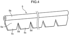
FIG. 4 is an overall perspective view of another example of the holding member illustrated as a modification of the present invention, the holding member configured to be fixed to the inward-suspending portion ofFIG. 2 , the holding member having a plate portion of a shape made up of a series of trapezoidal projections; -
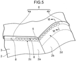
FIG. 5 is a perspective explanatory view showing a state in which the holding member ofFIG. 3 is fixed to the inward-suspending portion ofFIG. 2 ; -
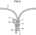
FIG. 6 is a cross-sectional view of the inward-suspending portion of the outer cover and the holding member that extend along a curved surface portion of the pad, the cross-sectional view being taken along a line VI-VI inFIG. 5 ; -
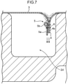
FIG. 7 is a cross-sectional view of the interior of a space formed on the curved surface portion of the pad, the cross-sectional view being taken along line VI-VI inFIG. 5 , showing a view for describing that the inward-suspending portion and the holding member move into the space because of a restitutive force of the holding member; and -
FIG. 8 is a perspective explanatory view for describing that the inward-suspending portion and the holding member ofFIG. 5 move into the space because of the restitutive force of the holding member. - A preferred embodiment of the present invention will hereinafter be described with reference to the drawings.
- As shown in
FIG. 1 , an automobile seat 1as an embodiment of a seat of the present invention, includes a seat cushion that supports the buttocks of a seated person. As shown inFIGS. 1 and2 , the seat cushion includes apad 2 and anouter cover 3 covering the surface of thepad 2. Theautomobile seat 1 ofFIG. 1 includes a seat back that supports the back of the seated person. This seat back, however, is omitted fromFIG. 1 . - The
pad 2 is a soft member fabricated by integrally molding a foaming resin, such as urethane. As shown inFIG. 2 , thepad 2 has aflat surface portion 2a (a second surface) and acurved surface portion 2b (a first surface). Theflat surface portion 2a is a portion that supports the buttocks of the seated person sitting on theseat 1. Thecurved surface portion 2b is a portion that is continuous with theflat surface portion 2a at its rear side (right side inFIG. 2 ) and that rises in a semi-cylindrical shape. Thiscurved surface portion 2b has an opening (not illustrated) or the like through which a connector of a child seat can be fitted. - In this embodiment, the
curved surface portion 2b corresponds to the first surface of the present invention, the first surface having a given curvature radius. Theflat surface portion 2a corresponds to the second surface of the present invention, the second surface having a curvature radius larger than that of thecurved surface portion 2b (the first surface), that is, theflat surface portion 2a is gently curved or flat. In this embodiment, theflat surface portion 2a formed of a flat surface is adopted as the second surface. In place of such aflat surface portion 2a, however, a gentle curved surface with a curvature radius larger than that of thecurved surface portion 2b may be adopted as the second surface. - On the
flat surface portion 2a and thecurved surface portion 2b of thepad 2, agroove 2c and aspace 2d are formed respectively in succession, as recesses corresponding to an inward-suspending portion 4 of theouter cover 3. Thegroove 2c formed on theflat surface portion 2a and thespace 2d formed on thecurved surface portion 2b extend in the front-to-rear direction of the seat 1 (left-to-right direction inFIG. 2 ). - The
space 2d has a sectional area larger than that of thegroove 2c. More specifically, thespace 2d is a space in which a child seat fitting portion connectable to a metal fitting of the child seat, which will be described later, can be stored. Thisspace 2d has a size that allows the inward-suspendingportion 4 to move into thespace 2d by means of theholding member 5 with the inward-suspendingportion 4 receiving a restitutive force of theholding member 5. - The
outer cover 3 is a member formed of a single layer of a filmy material, such as leather, synthetic leather, and fabric, or formed of two or more layers of a filmy material including nonwoven fabric, foamed resin, or the like. Theouter cover 3 is formed by joining together ends of a plurality of filmy materials by sewing (see asewn portion 7 inFIG. 6 ) or the like. A portion where ends of adjacent filmy materials are joined together by thesewn portion 7 forms the inward-suspending portion 4. In other words, theouter cover 3 has the inward-suspending portion 4 (seeFIG. 6 ) that projects from a side facing the pad 2 (lower side inFIG. 2 ) toward thepad 2 and that is inwardly suspended (drawn) in thepad 2. - The inward-suspending
portion 4 has a part extending continuously from theflat surface portion 2a to thecurved surface portion 2b of thepad 2. Specifically, as shown inFIG. 2 , the inward-suspendingportion 4 of this embodiment has astraight portion 4a that is inserted in thegroove 2c of theflat surface portion 2a of thepad 2 and that linearly extends along thegroove 2c, and acurved portion 4b that is disposed in thespace 2d of thecurved surface portion 2b of thepad 2 and that extends in a curved shape along thecurved surface portion 2b because of the restitutive force of the holding member 5 (specifically, the restitutive force of a reinforcingportion 5b, which will be described later). - As shown in
FIG. 1 , on a part ofouter cover 3 that covers thecurved surface portion 2b (first surface) of thepad 2, a slit S, into which the metal fitting (specifically, the connector of the ISOFIX-standard child seat) for fitting the child seat to the seat is inserted, is formed in a place close to the inward-suspending portion 4 (specifically, close to thecurved portion 4b) and communicating with thespace 2d of thepad 2. The slit S extends in parallel with thecurved portion 4b of the inward-suspendingportion 4. - As shown in
FIGS. 3 to 8 , theseat 1 of this embodiment includes theholding member 5 that holds the shape of the inward-suspendingportion 4 of theouter cover 3. - The
holding member 5 has bending-allowing elasticity and is configured to be capable of holding the shape of the inward-suspendingportion 4. - Specifically, as shown in
FIG. 3 , theholding member 5 is an elongated member extending along the inward-suspending portion 4, and has aplate portion 5a and the reinforcingportion 5b that reinforces theplate portion 5a. Theplate portion 5a and the reinforcingportion 5b are formed integrally out of a resin having bending-allowing elasticity. - The
plate portion 5a is an elongated tabular portion extending along the inward-suspendingportion 4. In a state of being in surface contact with the inward-suspendingportion 4, theplate portion 5a is fixed to the inward-suspendingportion 4. The present invention puts no limits on methods of fixing theplate portion 5a to the inward-suspendingportion 4, however, as shown inFIG. 6 , theplate portion 5a is sewn onto the inward-suspendingportion 4 with a thread to form the sewnportion 6, where theplate portion 5a is fixed. Fixing methods other than sewing can be adopted, which include heat sealing and bonding. It is preferable that the holdingmember 5 be made of a material, such as a resin, having hardness that at least allows sewing of theplate portion 5a (namely, theplate portion 5a is penetratable by a needle.). - The
plate portion 5a inFIG. 3 has slits orrecesses 5d that allow theplate portion 5a to be bent along the curved surface of thecurved surface portion 2b of thepad 2. Specifically, theplate portion 5a has a wavy shape on its lower end part, the wavy shape being formed ofprojections 5c and therecesses 5d arranged alternately in succession. The interval (pitch) betweenadjacent recesses 5d (oradjacent projections 5c) is determined to be about 12 mm. - It should be noted that what is required for the shape of the
plate portion 5a is to have the slits orrecesses 5d that allow theplate portion 5a to be bent along the curved surface ofcurved surface portion 2b ofpad 2. The shape of theplate portion 5a is, therefore, not limited to the above wavy shape. A modification of the present invention, for example, is shown inFIG. 4 . As shown inFIG. 4 , theplate portion 5a may be formed oftrapezoidal projections 5c and wedge-shapedslits 5d that are arranged alternately in succession. - The reinforcing
portion 5b is connected to theplate portion 5a continuously along the longitudinal direction of theplate portion 5a. The reinforcingportion 5b is structured to have flexural rigidity higher than that of theplate portion 5a so that the reinforcingportion 5b can reinforce theplate portion 5a. For example, the reinforcingportion 5b shown inFIGS. 3 and4 has a cylindrical shape or an elliptic cylindrical shape. The reinforcingportion 5b has, for example, a vertically oblong elliptic section of 5 mm in major axis and 3 mm in minor axis. - As shown in
FIG. 5 , the holdingmember 5 is fixed to a part of inward-suspendingportion 4 that continuously extends from theflat surface portion 2a to thecurved surface portion 2b of thepad 2, that is, fixed to thestraight portion 4a and thecurved portion 4b. In this embodiment, as shown inFIG. 6 , theplate portion 5a of the holdingmember 5 is sewn onto the inward-suspendingportion 4 of theouter cover 3 along the whole length of theplate portion 5a. This creates the sewnportion 6. The holdingmember 5 and its sewnportion 6 are disposed in such a way as to extend in parallel with a sewnportion 7 for forming the inward-suspendingportion 4 of the outer cover 3 (that is, in such a way as to extend in parallel with the direction perpendicular to the paper surface ofFIG. 6 ). It is preferable that the reinforcingportion 5b of the holdingmember 5 be located close to the sewnportion 7 of the inward-suspendingportion 4. - The
plate portion 5a of the holdingmember 5, theplate portion 5a extending along the shape of thepad 2, is fixed to the inward-suspendingportion 4 of theouter cover 3 by the sewnportion 6 in such a way as to conform to the shape of the outer cover. In other words, on thecurved surface portion 2b of thepad 2, as the holdingmember 5 is bent along the curved surface of thecurved surface portion 2b with allowing restitutive deformation of the holdingmember 5, theplate portion 5a is sewn onto the part of inward-suspendingportion 4 that corresponds to thecurved portion 4b along the shape of the outer cover. As a result, the restitutive force of the holding member 5 (specifically, the restitutive force of the reinforcingportion 5b) allows thecurved portion 4b of the inward-suspendingportion 4 to extend in a curved shape along thecurved surface portion 2b of thepad 2. - (1) According to the
seat 1 configured in the above manner, as shown inFIGS. 5 to 8 , the inward-suspendingportion 4 of theouter cover 3 is fixed only to theflat surface portion 2a of thepad 2, and is disposed on thecurved surface portion 2b in a state of the inward-suspendingportion 4 being bent together with the holdingmember 5 along the curved surface of thecurved surface portion 2b. In other words, the inward-suspendingportion 4 of theouter cover 3 extends continuously from thecurved surface portion 2b to theflat surface portion 2a of thepad 2, thecurved surface portion 2b and theflat surface portion 2a being different in curvature radius from each other. The holdingmember 5 having bending-allowing elasticity is fixed to thestraight portion 4a and thecurved portion 4b of the inward-suspendingportion 4 of theouter cover 3, thestraight portion 4a andcurved portion 4b extending continuously from thecurved surface portion 2b to theflat surface portion 2a of thepad 2. - The inward-suspending
portion 4 is fixed only to theflat surface portion 2a (i.e., the surface with a larger curvature radius) of thepad 2, specifically, to thegroove 2c of theflat surface portion 2a. Specifically, thestraight portion 4a of the inward-suspendingportion 4, thestraight portion 4a extending along thegroove 2c of theflat surface portion 2a of thepad 2, is fastened to a metal bar or the like inside thepad 2, the metal bar being near the bottom wall of thegroove 2c, by using a fixingmember 8, such as a hogring shown inFIG. 5 (seeFIG. 5 ). This creates an inward-suspending shape extending along theflat surface portion 2a. Meanwhile, thecurved portion 4b of the inward-suspendingportion 4, thecurved portion 4b extending along thespace 2d of thecurved surface portion 2b of thepad 2, is disposed on thecurved surface portion 2b in a state of thecurved portion 4b being bent together with the holdingmember 5 along the curved surface of thecurved surface portion 2b with a smaller curvature radius. - Specifically, the
outer cover 3 is stretched over thecurved surface portion 2b of thepad 2 in such a way as to keep theouter cover 3 in a tensioned state, and the peripheral edge of theouter cover 3 is fixed to a side surface or the back surface of thepad 2. At this time, the tension of theouter cover 3 is cut off by the slit S near the inward-suspendingportion 4, and therefore the tension does not directly act on the inward-suspending portion 4 (which means that the tension of theouter cover 3 is cut off from the inward-suspending portion 4). As a result, the shape retaining force of theouter cover 3 itself and the tension (restitutive force) of the holdingmember 5 work to cause theouter cover 3 to move downward inside thespace 2d. Hence a natural inward-suspending shape is created. - In this manner, in the inward-suspending
portion 4, thestraight portion 4a on theflat surface portion 2a side is fixed to theflat surface portion 2a of thepad 2; on the other hand, thecurved portion 4b on thecurved surface portion 2b side is not fixed to thecurved surface portion 2b but is held in a shape conforming to the curved surface of thecurved surface portion 2b because of the restitutive force of the holdingmember 5 in its bent state. In other words, thecurved portion 4b being on thecurved surface portion 2b side of the inward-suspendingportion 4, is caused to move into thespace 2d of thecurved surface portion 2b of thepad 2 by the holdingmember 5 in the bent state. Thus, even when the curved surface of thepad 2 is not supported, the inward-suspending shape can be created. - (2) According to the
seat 1 of this embodiment, as shown inFIG. 7 , thespace 2d is formed on thecurved surface portion 2b of thepad 2 as the recess corresponding to the inward-suspendingportion 4, thespace 2d being necessary for creating the inward-suspending shape. Thespace 2d has the size that allows the inward-suspendingportion 4 to move into thespace 2d by means of the holdingmember 5 with the inward-suspendingportion 4 receiving the restitutive force of the holdingmember 5. - In this configuration, the inward-suspending
portion 4 receiving the restitutive force of the holdingmember 5 is allowed to move into thespace 2d formed on thecurved surface portion 2b of thepad 2. Using the restitutive force of the holdingmember 5 effectively, therefore, the inward-suspendingportion 4 can be formed into the shape conforming to the curved surface of thecurved surface portion 2b and be held in such a shape. - As the recess corresponding to the inward-suspending
portion 4 formed on thecurved surface portion 2b, a through-hole or a slit penetrating thepad 2 from the front to the back thereof may be formed in place of thespace 2d with a bottom shown inFIG. 7 . Such a case offers the same effects as described above. - According to this embodiment, in particular, on the part of
outer cover 3 that covers thecurved surface portion 2b (first surface) of thepad 2, the slit S, into which the metal fitting for fitting the child seat can be inserted, is formed in the place near the inward-suspendingportion 4. In addition, thespace 2d, in which the child seat fitting portion connectable to the metal fitting can be placed, is formed as the recess. It is thus possible in this configuration that, on thecurved surface portion 2b (first surface) of thepad 2, thespace 2d, in which the child seat fitting portion can be placed, is secured as the inward-suspendingportion 4 is formed into the shape conforming to the curved surface of thecurved surface portion 2b, using the restitutive force of the holdingmember 5 effectively, and is held in such a shape. - (3) According to the
seat 1 of this embodiment, theflat surface portion 2a formed of a flat surface is adopted as the second surface of thepad 2 of the present invention. In this configuration, when thepad 2 has thecurved surface portion 2b formed of a curved surface and theflat surface portion 2a formed of a flat surface, the inward-suspendingportion 4 is fixed to the flat surface of theflat surface portion 2a of thepad 2, and at the same time, the inward-suspendingportion 4 is held in the shape conforming to the curved surface of thecurved surface portion 2b by the restitutive force of the holdingmember 5. As a result, in the case where thepad 2 includes both the flat surface and the curved surface, the inward-suspending shape extending continuously along the curved surface and the flat surface can be created. - (4) According to the
seat 1 of this embodiment, the holdingmember 5 has theplate portion 5a that extends along the inward-suspendingportion 4 and that is fixed in surface contact with the inward-suspendingportion 4. Theplate portion 5a has the slits orrecesses 5d that allow theplate portion 5a to be bent along the curved surface of thecurved surface portion 2b. - In this configuration, because the
plate portion 5a of the holdingmember 5 has the slits or therecesses 5d, these slits or therecesses 5d provide a space for movement along the surface of theplate portion 5a when theplate portion 5a is bent. This allows theplate portion 5a of the holdingmember 5 to be bent and fixed along the curved surface of thecurved surface portion 2b in a state of theplate portion 5a being in surface contact with the inward-suspendingportion 4. The holdingmember 5 is thus able to surely hold the inward-suspendingportion 4 in the shape conforming to the curved surface of thecurved surface portion 2b. - (5) According to the
seat 1 of this embodiment, the holdingmember 5 has the reinforcingportion 5b for reinforcing theplate portion 5a which is continuously connected to theplate portion 5a along its longitudinal direction. - In this configuration, because the holding
member 5 has the reinforcingportion 5b for reinforcing theplate portion 5a, the holdingmember 5 can be bent along the first curved surface without causing theplate portion 5a to buckle or wrinkle. Thus, the holdingmember 5 moves to a position at which the tension of the reinforcingportion 5b acts on a shape fixed by theplate portion 5a, specifically, a shape along the curved surface, thus being able to surely hold the inward-suspendingportion 4 in the shape conforming to the curved surface of thecurved surface portion 2b. - In the above embodiment, the holding
member 5 has theplate portion 5a and the reinforcingportion 5b of a cylindrical shape. The holdingmember 5 of the present invention, however, is not limited to this configuration. The holdingmember 5 may be composed of a linear member, a cylindrical member, or the like without having theplate portion 5a. In such a case, the linear member or the cylindrical member may be fixed to the inward-suspendingportion 4 by bonding or the like. - The above embodiment is summarized as follows.
- A seat of this embodiment comprises: a pad having a first surface formed of a curved surface with a given curvature radius and a second surface formed of a curved surface with a curvature radius larger than that of the first surface or formed of a flat surface; an outer cover that covers the pad, the outer cover having an inward-suspending portion projecting from a side facing the pad toward the pad and inwardly suspended in the pad; and a holding member having bending-allowing elasticity, the holding member holding a shape of the inward-suspending portion (specifically, a shape of the inward-suspending portion and of the outer cover around the inward-suspending portion), wherein the inward-suspending portion extends continuously from the first surface to the second surface of the pad, wherein the holding member is fixed to a part of the inward-suspending portion, the part extending continuously from the first surface to the second surface of the pad, and wherein the inward-suspending portion is fastened only to the second surface of the pad, and is disposed on the first surface in a state of the inward-suspending portion being bent together with the holding member along the curved surface of the first surface.
- According to this configuration, the inward-suspending portion of the outer cover extends continuously from the first surface to the second surface of the pad, the first surface and the second surface being different in curvature radius from each other. The holding member having bending-allowing elasticity is fixed to the part of the inward-suspending portion of the outer cover, the part extending continuously from the first surface to the second surface of the pad. Because the inward-suspending portion is fixed only to the second surface (that is, the surface with a larger curvature radius) of the pad, an inward-suspending shape conforming to the second surface is formed, and the inward-suspending portion is disposed along the curved surface of the first surface with a smaller curvature radius in a state of the inward-suspending portion being bent together with the holding member. Accordingly, the inward-suspending portion is fixed to the second surface of the pad; while, in spite of not being fixed to the first surface, the inward-suspending portion is held in a shape conforming to the curved surface of the first surface because of a restitutive force of the holding member in its bent state. Thus, even when the curved surface of the pad is not supported, the inward-suspending shape can be created.
- On the above seat, a recess corresponding to the inward-suspending portion is formed on the first surface of the pad, and the recess should preferably have a size that allows the inward-suspending portion to move into the recess by means of the holding member with the inward-suspending portion receiving the restitutive force of the holding member.
- In this configuration, the inward-suspending portion receiving the restitutive force of the holding member is allowed to move into the recess formed on the first surface of the pad. Using the restitutive force of the holding member effectively, therefore, the inward-suspending portion can be formed into the shape conforming to the curved surface of the first surface and be held in such a shape.
- According to the seat described above, on a part of outer cover that covers the first surface, a slit, into which a metal fitting for fitting a child seat to the seat is inserted, is formed in a place near the inward-suspending portion, and the recess has a space in which a child seat fitting portion connectable to the metal fitting can be placed. It is preferable that the space has a size that allows the inward-suspending portion to move into the space by means of the holding member with the inward-suspending portion receiving the restitutive force of the holding member.
- In this configuration, on the part of outer cover that covers the first surface, the slit, into which the metal fitting for fitting the child seat can be inserted, is formed in the place near the inward-suspending portion, and the recess has the space in which the child seat fitting portion connectable to the metal fitting can be placed. In this configuration, the inward-suspending portion receiving the restitutive force of the holding member is allowed to move into the space formed on the first surface of the pad. It is thus possible that the space in which the child seat fitting portion can be placed is provided on the first surface of the pad as the inward-suspending portion is formed into the shape conforming to the curved surface of the first surface, using the restitutive force of the holding member effectively, and is held in such a shape.
- It is preferable that on the above seat, the second surface be formed of a flat surface.
- In this configuration, when the pad has the first surface formed of a curved surface and the second surface formed of a flat surface, the inward-suspending portion is fixed to the flat surface of the second surface of the pad; while, the inward-suspending portion is held in the shape conforming to the curved surface of the first surface by the restitutive force of the holding member. As a result, in the case where the pad includes both the flat surface and the curved surface, an inward-suspending shape extending continuously along the curved surface and the flat surface can be created.
- According to the above seat, the holding member has a plate portion that extends along the inward-suspending portion and that is fixed in surface contact with the inward-suspending portion. Therefore, the plate portion should preferably have a slit or a recess that allows the plate portion to be bent along the curved surface of the first surface.
- In this configuration, having the slit or the recess, the plate portion of the holding member can be bent and fixed along the curved surface of the first surface in a state of the plate portion being in surface contact with the inward-suspending portion. The holding member is thus able to hold the inward-suspending portion certainly in the shape conforming to the curved surface of the first surface.
- According to the seat described above, it is preferable that the holding member have a reinforcing portion for reinforcing the plate portion that is continuously connected to the plate portion along its longitudinal direction.
- In this configuration, because the holding member has the reinforcing portion reinforcing the plate portion, the holding member can be bent along the first curved surface without causing the plate portion to buckle or wrinkle. As a result, the holding member moves to a position at which the tension of the reinforcing portion acts on a shape fixed by the plate portion, specifically, a shape along the curved surface, thus being able to surely hold the inward-suspending portion in the shape conforming to the curved surface of the first surface.
- According to the seat of this embodiment, an inward-suspending shape conforming to the curved surface of the pad can be created.
Claims (6)
- A seat comprising:a pad having a first surface formed of a curved surface with a given curvature radius and a second surface formed of a curved surface with a curvature radius larger than that of the first surface or formed of a flat surface;an outer cover that covers the pad, the outer cover having an inward-suspending portion projecting from a side facing the pad toward the pad and inwardly suspended in the pad; anda holding member having bending-allowing elasticity, the holding member holding a shape of the inward-suspending portion,wherein the inward-suspending portion extends continuously from the first surface to the second surface of the pad,the holding member is fixed to a part of the inward-suspending portion, the part extending continuously from the first surface to the second surface of the pad, andthe inward-suspending portion is fastened only to the second surface of the pad, and is disposed on the first surface in a state of the inward-suspending portion being bent together with the holding member along the curved surface of the first surface.
- The seat according to claim 1, whereina recess corresponding to the inward-suspending portion is formed on the first surface of the pad, andthe recess has a size that allows the inward-suspending portion to move into the recess by means of the holding member with the inward-suspending portion receiving the restitutive force of the holding member.
- The seat according to claim 2, whereina slit into which a metal fitting for fitting a child seat to the seat is inserted is formed in a place near the inward-suspending portion on a part of the outer cover, the part covering the first surface,the recess has a space in which a child seat fitting portion connectable to the metal fitting is placed, andthe space has a size that allows the inward-suspending portion to move into the space by means of the holding member with the inward-suspending portion receiving the restitutive force of the holding member.
- The seat according to any one of claims 1 to 3, wherein the second surface is formed of a flat surface.
- The seat according to any one of claims 1 to 4, whereinthe holding member has a plate portion that extends along the inward-suspending portion and that is fixed to the inward-suspending portion in a state of the holding member being in surface contact with the inward-suspending portion, andthe plate portion has a slit or a recess that allows the plate portion to be bent along a curved surface of the first surface.
- The seat according to claim 5, wherein the holding member has a reinforcing portion for reinforcing the plate portion that is continuously connected to the plate portion along a longitudinal direction of the plate portion.
Applications Claiming Priority (2)
| Application Number | Priority Date | Filing Date | Title |
|---|---|---|---|
| JP2019139847A JP7277916B2 (en) | 2019-07-30 | 2019-07-30 | sheet |
| PCT/JP2020/025593 WO2021020000A1 (en) | 2019-07-30 | 2020-06-29 | Seat |
Publications (2)
| Publication Number | Publication Date |
|---|---|
| EP3970567A1 true EP3970567A1 (en) | 2022-03-23 |
| EP3970567A4 EP3970567A4 (en) | 2022-09-07 |
Family
ID=74229972
Family Applications (1)
| Application Number | Title | Priority Date | Filing Date |
|---|---|---|---|
| EP20847085.6A Withdrawn EP3970567A4 (en) | 2019-07-30 | 2020-06-29 | SEAT |
Country Status (5)
| Country | Link |
|---|---|
| US (1) | US20220355714A1 (en) |
| EP (1) | EP3970567A4 (en) |
| JP (1) | JP7277916B2 (en) |
| CN (1) | CN114144334A (en) |
| WO (1) | WO2021020000A1 (en) |
Family Cites Families (20)
| Publication number | Priority date | Publication date | Assignee | Title |
|---|---|---|---|---|
| JPH0340231Y2 (en) * | 1986-05-20 | 1991-08-23 | ||
| FR2730198B1 (en) * | 1995-02-08 | 1997-04-11 | Faure Bertrand Equipements Sa | HEADDRESS FOR VEHICLE SEAT BACKREST AND SEAT INCLUDING SUCH A HEADDRESS |
| JP4841190B2 (en) * | 2005-07-27 | 2011-12-21 | Ykk株式会社 | Jade core material |
| JP5600024B2 (en) * | 2010-03-30 | 2014-10-01 | 三井物産テクノプロダクツ株式会社 | Seat material and vehicle seat and recovery seat using the seat material |
| JP5943859B2 (en) * | 2013-02-27 | 2016-07-05 | 株式会社タチエス | Vehicle seat |
| JP6173837B2 (en) * | 2013-08-29 | 2017-08-02 | トヨタ紡織株式会社 | Jade |
| JP6276042B2 (en) | 2014-01-22 | 2018-02-07 | テイ・エス テック株式会社 | Vehicle seat |
| JP5940567B2 (en) * | 2014-01-27 | 2016-06-29 | トヨタ紡織株式会社 | Vehicle seat |
| JP6243247B2 (en) * | 2014-02-17 | 2017-12-06 | デルタ工業株式会社 | Child seat locking device |
| JPWO2015170675A1 (en) * | 2014-05-07 | 2017-04-20 | 住江織物株式会社 | Skin material for vehicle seats |
| JP2016107801A (en) * | 2014-12-05 | 2016-06-20 | 株式会社東洋シート | Vehicular seat back |
| JP2016112179A (en) * | 2014-12-15 | 2016-06-23 | テイ・エス テック株式会社 | Seat |
| JP2016141186A (en) * | 2015-01-30 | 2016-08-08 | 株式会社タチエス | Vehicle seat |
| JP6674767B2 (en) * | 2015-11-30 | 2020-04-01 | セーレン株式会社 | Vehicle seat cover |
| JP6690972B2 (en) * | 2016-03-18 | 2020-04-28 | トヨタ紡織株式会社 | Beads and vehicle interior parts equipped with beads |
| JP6970335B2 (en) * | 2017-06-19 | 2021-11-24 | テイ・エス テック株式会社 | Vehicle seat |
| JP7080717B2 (en) * | 2018-05-08 | 2022-06-06 | 株式会社タチエス | Suspenders to prevent deep fastening of cover suspension members and seats for automobiles using them |
| JP7070227B2 (en) * | 2018-08-09 | 2022-05-18 | トヨタ紡織株式会社 | Vehicle seat |
| JP7180550B2 (en) * | 2019-06-19 | 2022-11-30 | トヨタ紡織株式会社 | vehicle seat |
| JP7299186B2 (en) * | 2020-03-19 | 2023-06-27 | トヨタ自動車株式会社 | vehicle seat |
-
2019
- 2019-07-30 JP JP2019139847A patent/JP7277916B2/en active Active
-
2020
- 2020-06-29 CN CN202080047580.3A patent/CN114144334A/en active Pending
- 2020-06-29 EP EP20847085.6A patent/EP3970567A4/en not_active Withdrawn
- 2020-06-29 WO PCT/JP2020/025593 patent/WO2021020000A1/en not_active Ceased
- 2020-06-29 US US17/623,224 patent/US20220355714A1/en not_active Abandoned
Also Published As
| Publication number | Publication date |
|---|---|
| US20220355714A1 (en) | 2022-11-10 |
| WO2021020000A1 (en) | 2021-02-04 |
| JP7277916B2 (en) | 2023-05-19 |
| EP3970567A4 (en) | 2022-09-07 |
| JP2021020630A (en) | 2021-02-18 |
| CN114144334A (en) | 2022-03-04 |
Similar Documents
| Publication | Publication Date | Title |
|---|---|---|
| US10202057B2 (en) | Surface skin-fastening structure for vehicle seat, operation lever device for vehicle seat, and vehicle seat | |
| US6152534A (en) | Seat having seating face made of sheet resilient material | |
| EP2070763B1 (en) | Pieces for skin members of vehicular seats and methods of manufacturing the same | |
| US11013342B2 (en) | Conveyance seat and seat cover for the same | |
| US20100259079A1 (en) | Cover material terminal treating member, seat part, and vehicle seat | |
| US8511754B2 (en) | Upholstered seat element | |
| US10093212B2 (en) | Vehicle seat | |
| JP2009148407A (en) | Skin material hanging structure | |
| US10166892B2 (en) | Pad | |
| EP0858926A1 (en) | Upholstery securing device for motor-vehicle articles such as headrests and the like | |
| EP3970567A1 (en) | Seat | |
| US20200375371A1 (en) | End Member for Fastening Cover Material | |
| EP3235405B1 (en) | Seat | |
| JP4381283B2 (en) | Vehicle seat | |
| JP7618370B2 (en) | Seat pad and manufacturing method thereof | |
| JP6533156B2 (en) | Vehicle seat | |
| JP5821377B2 (en) | Vehicle seat pad | |
| JP2018188109A (en) | Vehicle seat pad | |
| WO2017122392A1 (en) | Headrest device and method for manufacturing headrest device | |
| JP7431102B2 (en) | vehicle seat | |
| JP4481787B2 (en) | Seat cushion pad | |
| JP7633488B2 (en) | Sheet | |
| JP7021892B2 (en) | Vehicle seat | |
| JP6916700B2 (en) | Vehicle seat | |
| KR20240100352A (en) | child seat |
Legal Events
| Date | Code | Title | Description |
|---|---|---|---|
| STAA | Information on the status of an ep patent application or granted ep patent |
Free format text: STATUS: THE INTERNATIONAL PUBLICATION HAS BEEN MADE |
|
| PUAI | Public reference made under article 153(3) epc to a published international application that has entered the european phase |
Free format text: ORIGINAL CODE: 0009012 |
|
| STAA | Information on the status of an ep patent application or granted ep patent |
Free format text: STATUS: REQUEST FOR EXAMINATION WAS MADE |
|
| 17P | Request for examination filed |
Effective date: 20211217 |
|
| AK | Designated contracting states |
Kind code of ref document: A1 Designated state(s): AL AT BE BG CH CY CZ DE DK EE ES FI FR GB GR HR HU IE IS IT LI LT LU LV MC MK MT NL NO PL PT RO RS SE SI SK SM TR |
|
| REG | Reference to a national code |
Ref country code: DE Ref legal event code: R079 Free format text: PREVIOUS MAIN CLASS: A47C0031020000 Ipc: B60N0002580000 |
|
| A4 | Supplementary search report drawn up and despatched |
Effective date: 20220805 |
|
| RIC1 | Information provided on ipc code assigned before grant |
Ipc: B60N 2/28 20060101ALI20220801BHEP Ipc: B68G 7/052 20060101ALI20220801BHEP Ipc: A47C 31/02 20060101ALI20220801BHEP Ipc: B60N 2/58 20060101AFI20220801BHEP |
|
| DAV | Request for validation of the european patent (deleted) | ||
| DAX | Request for extension of the european patent (deleted) | ||
| GRAP | Despatch of communication of intention to grant a patent |
Free format text: ORIGINAL CODE: EPIDOSNIGR1 |
|
| STAA | Information on the status of an ep patent application or granted ep patent |
Free format text: STATUS: GRANT OF PATENT IS INTENDED |
|
| INTG | Intention to grant announced |
Effective date: 20230223 |
|
| STAA | Information on the status of an ep patent application or granted ep patent |
Free format text: STATUS: THE APPLICATION IS DEEMED TO BE WITHDRAWN |
|
| 18D | Application deemed to be withdrawn |
Effective date: 20230706 |