EP3970545B1 - Vorrichtung, insbesondere visiermechanismus, zum verlagern eines visiers an einem helm und kopfschutzsystem - Google Patents
Vorrichtung, insbesondere visiermechanismus, zum verlagern eines visiers an einem helm und kopfschutzsystem Download PDFInfo
- Publication number
- EP3970545B1 EP3970545B1 EP21193573.9A EP21193573A EP3970545B1 EP 3970545 B1 EP3970545 B1 EP 3970545B1 EP 21193573 A EP21193573 A EP 21193573A EP 3970545 B1 EP3970545 B1 EP 3970545B1
- Authority
- EP
- European Patent Office
- Prior art keywords
- visor
- connection means
- helmet
- transfer position
- closed position
- Prior art date
- Legal status (The legal status is an assumption and is not a legal conclusion. Google has not performed a legal analysis and makes no representation as to the accuracy of the status listed.)
- Active
Links
Images


Classifications
-
- A—HUMAN NECESSITIES
- A42—HEADWEAR
- A42B—HATS; HEAD COVERINGS
- A42B3/00—Helmets; Helmet covers ; Other protective head coverings
- A42B3/04—Parts, details or accessories of helmets
- A42B3/18—Face protection devices
- A42B3/185—Securing goggles or spectacles on helmet shells
-
- A—HUMAN NECESSITIES
- A42—HEADWEAR
- A42B—HATS; HEAD COVERINGS
- A42B3/00—Helmets; Helmet covers ; Other protective head coverings
- A42B3/04—Parts, details or accessories of helmets
- A42B3/18—Face protection devices
- A42B3/22—Visors
- A42B3/221—Attaching visors to helmet shells, e.g. on motorcycle helmets
- A42B3/222—Attaching visors to helmet shells, e.g. on motorcycle helmets in an articulated manner, e.g. hinge devices
- A42B3/223—Attaching visors to helmet shells, e.g. on motorcycle helmets in an articulated manner, e.g. hinge devices with means for locking the visor in a fully open, intermediate or closed position
Definitions
- the invention relates to a device, in particular a visor mechanism, for displacing a visor on a helmet. Furthermore, the invention relates to a head protection system with such a device.
- Head protection systems comprising a helmet, a visor, and a device for moving the visor on the helmet are known.
- the visor of these head protection systems can be manually moved between a closed and an open position.
- a disadvantage is that moving the visor between the closed and open positions requires practice, since the movement of the visor relative to the helmet, as determined by the device, is not visible to the user, and the movement of both sides of the visor relative to the helmet must also be synchronized.
- a device for displacing a visor on a helmet comprises a guide means for guided displacement a visor connection means relative to a helmet connection means between a closed position, via a transfer position into an open position, wherein at least one biasing means biases the visor connection means arranged in the transfer position both in the direction of The at least one pre-tensioning means secures the visor connection means in the closed position and the open position. This allows the visor connection means to be moved particularly reliably and comfortably between the closed position and the open position, in particular beyond the transfer position.
- the pre-tensioning force acting on the visor connection means and the visor provides the user with feedback about the movement path specified by the guide means.
- the at least one pre-tensioning means secures the visor connection means in the closed position and/or in the open position.
- the user is supported when moving the visor connection means from the transfer position to the closed position and/or open position. This avoids a force-free dead center in which the visor could be accidentally positioned but in which it is neither fixed in place nor adequately protects and/or uncovers the user's face. Because the displacement movement of the visor connection means relative to the helmet connection means is predetermined and pre-tensioned towards an end position at every point of the displacement path, the visor connection means can be moved particularly reliably, comfortably, and safely.
- Preloading the visor connection means arranged in the transfer position toward the closed position and toward the open position means that the at least one preloading means exerts a force on the visor connection means in the transfer position that is oriented in the direction of movement from the transfer position to the closed position or to the open position.
- the visor connection means is preloaded relative to the helmet connection means in the two displacement directions that lead out of the transfer position.
- the drive forces and/or drive moments produced by the at least one pretensioning means in the transfer position between the visor connection means and the helmet connection means are preferably non-collinear and/or non-parallel.
- the force vector and/or moment vector resulting in the transfer position between the visor connection means and the helmet connection means is preferably non-zero in the direction of the closed position and in the direction of the open position.
- the visor connection means can be displaceable between the closed position and the transfer position along a first movement path and/or between the transfer position and the open position along a second movement path.
- the guide means can be designed such that it limits the displaceability of the visor connection means relative to the helmet connection means to the first and/or the second movement path.
- the guide means is preferably designed such that a displacement of the visor connection means relative to the helmet connection means along the first and second movement paths is only possible in the transfer position.
- the respective movement path can determine a linear, in particular a rectilinear, displacement and/or a rotational displacement, in particular limiting the displaceability of the visor connection means relative to the helmet connection means to exclusively such degrees of freedom of movement.
- the first movement path and the second movement path preferably form the movement course of the visor connection means between the closed position and the open position.
- the first movement path and the second movement path can be adjacent to one another in the transfer position.
- the movement path in particular the first movement path and the second movement path, cannot be continuously differentiated in the transfer position.
- the smallest angle between the first movement path and the second movement path is a maximum of 135°, in particular a maximum of 120°, in particular a maximum of 100°, in particular a maximum of 90°, in particular a maximum of 60°, and/or at least 30°, in particular at least 60°, in particular at least 90°, in particular at least 100°.
- the sighting mechanism in particular the guide means and/or the pretensioning means, are designed such that, in the transfer position, a displacement movement of the sighting connection means in the direction of the closed position, in particular along the first movement path, can be blocked, while at the same time a displacement movement of the sighting connection means in the direction of the open position, in particular in the direction of the second movement path, is enabled.
- this applies equally in the opposite direction for a displacement movement of the sighting connection means in the direction of the closed position, in particular in the direction of the first movement path, when the second movement path is blocked.
- the displacement from the transfer position to the closed position and/or to the open position is preferably effected, in particular completely, by the at least one pretensioning means.
- the displacement of the visor connection means relative to the helmet connection means along the second movement path is enabled when the first movement path is completely blocked and/or enabled along the first movement path when the second movement path is completely blocked, in particular such that the enabled movement between the transfer position and the closed position and/or the open position can be fully executed.
- the displacement between the transfer position and the open position and/or the closed position is preferably effected entirely by the at least one pretensioning means.
- the at least one pretensioning means is designed to pretension the visor connection means arranged in the transfer position in the direction of the closed position and in the direction of the open position, it can be achieved that in the transfer position no change in the force vector exerted on the visor connection means, in particular by the user, is required in order to move the visor connection means into the transfer position and from the transfer position into the closed position and/or open position, in particular opposite the transfer position.
- the sighting mechanism in particular the guide means and/or the at least one pretensioning means, can be designed such that the sighting connection means locks from the transfer position into the open position and/or locks from the transfer position into the closed position.
- the guide means is designed such that it has at least one end stop for limiting the displacement movement of the visor connection means relative to the helmet connection means along the first movement path and/or along the second movement path in the transfer position.
- the guide means has at least one end stop for limiting the displacement movement of the visor connection means relative to the helmet connection means in the open position and/or in the closed position.
- the visor connection means can be designed for permanent or reversibly detachable connection to the visor.
- the visor connection means can also be formed as a single piece, in particular integrally with the visor.
- the helmet connection element can be permanently or reversibly connected to the helmet, in particular to a helmet shell. In particular, it can be firmly bonded to the helmet.
- closed position refers equally to the arrangement of the device, the visor connection means relative to the helmet connection means, and the visor relative to the helmet.
- the fact that the visor is closed in the closed position and open in the open position can be deduced from the device connected to the helmet and visor, but possibly not from the device in its uninstalled state.
- closed position and open position can be understood alternatively as a first position and a second position in connection with the device in its uninstalled state.
- the device comprises a cover which at least partially, in particular completely, covers the helmet connection means and/or the visor connection means and/or the guide means.
- the cover is preferably attachable, in particular reversibly detachable, to the helmet connection means.
- the cover, together with the helmet connection means, can form a housing in which the visor connection means and/or the guide means and/or the at least one pretensioning means are at least partially, in particular completely, accommodated. This advantageously ensures that components of the device that are movable relative to one another are concealed, in particular protected from interference and/or from contamination.
- the device can have at least one, in particular at least two, in particular at least three, in particular at least four of the pretensioning means. Preferably, the device has a maximum of four, in particular a maximum of two, of the pretensioning means.
- the at least one pretensioning means can be designed as a tension spring and/or a compression spring and/or a torsion spring and/or a bending spring and/or as a rubber-elastic body.
- the at least one pretensioning means can comprise a metallic material, in particular a spring steel and/or a plastic, or a rubber-elastic material.
- the rubber-elastic material preferably has a modulus of elasticity in a range from 1 MPa to 200 MPa, in particular from 10 MPa to 100 MPa, and/or a Shore A hardness in a range from 10 to 100, in particular from 20 to 60.
- At least one pretensioning means is preferably located between the helmet connection means and the visor connection means. The at least one pretensioning means can exert a pretensioning force and/or a pretensioning moment on the visor connection means.
- the guide means has at least one end stop for limiting the displaceability of the visor connection means relative to the helmet connection means, in particular in the closed position and/or in the open position.
- the preloading means can be designed to preload the sight connection means into the open position and/or the closed position, in particular to the respective end stop. This allows the sight connection means to be reliably fixed in the open position and/or the closed position.
- the guide means can have at least one guide resistance arranged between the closed position and the open position, and which requires a force to overcome.
- the guide resistance can be formed, for example, by an elastic element acting between the visor connection means and the helmet connection means.
- the guide resistance preferably comprises at least one, in particular two elastic or rigid elements, in particular locking lugs, which interact with an elastic or rigid counterpart, in particular a locking web.
- the elastic means can be arranged on the helmet connection means and the counterpart can be arranged on the visor connection means, or vice versa.
- the guide resistance is arranged adjacent to the transfer position along the displacement path of the visor connection means, in particular on the side of the closed position. This advantageously ensures that a specific position along the displacement path, in particular the transfer position, can be detected by the user. The visor can thus be displaced particularly reliably and conveniently.
- the guide means is designed such that the sight connection means is moved at least partially, in particular exclusively, linearly between the closed position and the transfer position.
- This linear movement is preferably oriented such that the sight moves from the closed position into the transfer position along a viewing direction of the user is moved forward, in particular in front of the helmet.
- the guide means can be designed such that the visor connection means is moved upwards, in particular linearly and/or pivoted, with respect to the user's line of sight when moved from the transfer position to the open position.
- a device according to claim 2 is particularly economical to manufacture and reliable in operation.
- a single pretensioning means is understood to be a pretensioning means which has a single operating principle, for example, is designed as a spiral spring, torsion spring, or tension spring, and/or has a single functional section and/or is formed in one piece, in particular with a material fit.
- the single pretensioning means pretensions the visor connection means arranged in the transfer position both in the direction of the closed position and in the direction of the open position.
- the pretensioning means can be arranged, for example, eccentrically to a rotational axis about which the visor connection means can be pivoted from the transfer position.
- the pretensioning means can create a drive torque from the transfer position between the visor connection means and the helmet connection means.
- the visor connection means can also be displaceable linearly relative to the helmet connection means, wherein the single pretensioning means also creates a drive force between the visor connection means and the helmet connection means in the direction of this linear displacement movement.
- the sole preloading means is preferably designed as a tension spring, in particular as a rubber-elastic spring, in particular as a rubber band and/or rubber ring. The number of components of the device is thus reduced, thereby reducing its assembly and manufacturing costs.
- a device according to claim 3 ensures the displacement of the visor connecting means in a particularly reliable, comfortable and safe manner.
- a pretensioning force generated by the at least one pretensioning means and/or a pretensioning moment generated by the at least one pretensioning means can be maximum in the transfer position.
- Such a device can be displaced particularly reliably between the closed position and the open position, in particular from the transfer position.
- the pretensioning force and/or the pretensioning moment are to be understood as the force and/or moment generated by the at least one pretensioning means and/or the force applied to the at least one pretensioning means. Because the pretensioning force and/or the pretensioning moment are maximum in the transfer position, an unintentional retention of the visor connection means in the transfer position is reliably prevented.
- a device ensures the displacement of the visor on the helmet in a particularly reliable manner.
- the driving force and/or the driving torque are understood to be the force and/or the torque produced by the at least one pretensioning means between the visor connection means and the helmet connection means.
- the pretensioning force and/or the pretensioning torque in particular their magnitude and orientation, and/or their force application points, in particular with respect to the visor connection means and/or the helmet connection means and/or the guide means, influence the produced driving force and/or the driving torque.
- the driving torque and the driving force are produced by the at least one pretensioning means in the transfer position, in particular in every position between the closed position and the open position, on the sight connection means.
- the device can have a single preloading means for this purpose.
- the preloading moment can cause the sight connection means to be moved from the transfer position to the open position
- the preloading force can cause the sight connection means to be moved from the transfer position to the closed position, or vice versa.
- a device is particularly flexibly adjustable with regard to supporting the displacement movement of the visor on the helmet.
- the forces and/or torques caused by the first and second pretensioning means are preferably not collinear.
- the two pretensioning means can be designed as two linear springs oriented obliquely to one another, in particular as tension springs and/or as two torsion springs arranged eccentrically to one another and/or as a torsion spring and a linear spring.
- the first and second pretensioning means can be formed as one piece, in particular by being integrally connected to one another. In this case, the respective pretensioning means forms an independent functional section of a combination spring.
- a device ensures the displacement of the visor on the helmet in a particularly comfortable and reliable manner.
- the kink in the movement path can be formed by a kink in a slotted guide and/or by the movement path following a pivoting movement from the transfer position to the open position and a linear movement to the closed position, or vice versa.
- the guide rail preferably comprises at least one, in particular at least two, in particular a maximum of three, in particular exactly two, guide rails.
- the at least one guide rail can comprise a guide element, in particular a guide groove and/or a guide slot and/or a guide frame and/or a guide rail.
- the at least one link preferably has a guide body, in particular a sliding block.
- the guide element can be designed for straight-line and/or curved, in particular circular-arc, guidance of the guide body.
- the guide element and the guide body are formed as one piece, in particular integrally, with one of the two components formed by the helmet connection means and the visor connection means.
- the helmet connection means and/or visor connection means and the respective component of the link can be manufactured using an injection molding process.
- the link guide, in particular the at least one link can be designed as a linear guide.
- a device according to claim 8 is particularly robust in operation and comfortable to use.
- the guide means can comprise exclusively joints for the guided displacement of the visor connection means relative to the helmet connection means.
- the guide means preferably comprises at least one, in particular at least two, and/or a maximum of four, in particular a maximum of three, in particular a maximum of two, preferably exactly two, joints.
- the joints ensure particularly low-friction displacement and are particularly robust against contamination.
- the visor connection means is attached to the helmet connection by means of a coupling element.
- the coupling element can be attached to the helmet connection means via a first joint.
- the visor connection means can be attached to the coupling element via a second joint.
- the axes of rotation of these two joints are oriented parallel to each other and/or positioned at a distance from each other. A distance between the axes of rotation of these joints is preferably in a range of 3 mm to 15 mm, in particular 5 mm to 10 mm.
- a device ensures the displacement of the visor on the helmet in a particularly user-friendly manner.
- the visor By displacing the visor connection means between the closed position and the transfer position with the essentially linear displacement movement, the visor can initially be moved away from the user's head and away from the front of the helmet. A gap between the helmet and the visor can thus be avoided.
- the visor can rest as tightly as possible on the user's nose. Accordingly, the freedom of movement required to displace the visor from the closed position does not have to be maintained.
- the angle by which the visor connection means is pivoted relative to the helmet connection means when displacing between the closed position and the transfer position is preferably in a range of 0° to 10°, in particular in a range of 2° to 10°.
- a device ensures the displacement of the visor on the helmet in a particularly convenient manner.
- the displacement of the visor connection means between the closed position and the transfer position preferably occurs purely linearly, in particular purely straight.
- the visor can thus be displaced in front of the helmet, i.e., into the transfer position, via the shortest possible path, and from this position can be guided over the helmet, i.e., into the open position.
- a device is particularly convenient to handle.
- the guide means is designed to move the visor connection means relative to the helmet connection means between the transfer position and from the open position, the displacement movement is to be moved exclusively in a rotational manner, in particular in a circular arc.
- the displacement movement transitions from a translational movement, in particular a purely translational movement, to a rotational movement, in particular a purely rotational movement.
- a device ensures particularly high operating comfort.
- the angle through which the visor connection means can be pivoted relative to the helmet connection is preferably in a range from 15° to 180°, in particular from 20° to 90°, in particular from 30° to 60°, in particular from 40° to 50° and/or is a maximum of 180°.
- the guide means is preferably designed such that the visor is displaced relative to the helmet between the transfer position and the open position in the vertical direction by a distance in a range from 10 mm to 60 mm, in particular from 25 mm to 50 mm.
- the displacement in the vertical direction can also be effected at least partially by a translational movement component of the visor relative to the helmet.
- a device is particularly convenient to operate.
- the handle can be attached to the visor connection means and/or the coupling element.
- the handle can be attached to the helmet connection means so as to be translationally and/or rotationally displaceable.
- the handle is attached to a cover, in particular formed integrally therewith.
- the handle and/or the guide means are preferably designed such that, by actuating the handle, the visor connection means can be displaced relative to the helmet connection means between the closed position and the transfer position and/or between the open position and the transfer position. This advantageously achieves the result that, in order to displace the visor on the helmet, the visor itself does not have to be grasped, which prevents visibility being impaired by dirt.
- a further object of the invention is to improve a head protection system, in particular to improve its operability and to ensure a particularly high level of safety during operation.
- the advantages of the head protection system correspond to the advantages of the device described above.
- the head protection system can be further developed with at least one of the features described above in connection with the device.
- the head protection system preferably has exactly two of the devices.
- One of the devices is preferably arranged on each side of the helmet and/or the visor. At least one, in particular all, axes of rotation of the devices are preferably arranged concentrically to one another.
- the visor In the closed position, the visor is preferably arranged flush with the helmet, in particular a helmet shell. In the open position, the visor is preferably arranged above its arrangement in the closed position and/or above an outer surface of the helmet, in particular the helmet shell.
- the head protection system 1 comprises a helmet 2 for protecting the head and a visor 3 for protecting the face, in particular the eyes.
- the visor 3 is displaceably attached to the helmet by means of two devices 4.
- the two devices 4 are arranged symmetrically on the helmet 2, in particular symmetrically to a vertical plane oriented parallel to the user's line of sight, preferably on both sides.
- the helmet 2 comprises a helmet shell 5, a shock absorber (not shown) and a chin strap (not shown).
- the visor 3 has a viewing glass 6 extending continuously over both eyes.
- the viewing glass 6 is held in a visor frame 7.
- the visor 3 In the closed position, in which the visor 3 is closed, the visor 3 is with regard to its outer contour, it is arranged flush with the outer contour of the helmet 2, in particular the helmet shell 5.
- the two devices 4 each have a helmet connection means 8, a visor connection means 9, a guide means 10, and a single pretensioning means 11.
- the helmet connection means 8 is firmly, in particular permanently, connected to the helmet 2, in particular to the helmet shell 5.
- the visor connection means 9 is firmly, in particular permanently, connected to the visor frame 7.
- a cover 12 of the device 4 covers the helmet connection means 8 and the visor connection means 9 at least partially and the guide means 10 completely.
- the guide means 10 which is in the Fig. 2 to Fig. 4 is shown in further detail, is designed for the guided displacement of the visor connection means 9 relative to the helmet connection means 8.
- the guide means 10 comprises a slotted guide with a first guide slot 13 and a second guide slot 14.
- the two guide slots 13, 14 each have a guide element 15, 16 and a guide body 17, 18 displaceably mounted therein or thereon.
- the first guide element 15 is designed as a rectilinear guide slot, in particular in the form of an elongated hole, in the helmet connection means 8.
- the first guide body 17 is designed as a bolt, in particular as a pin, on the visor connection means 9.
- the second guide element 16 is designed as a guide frame with a linear and a circular sector-shaped section on the helmet connection means 8.
- the second guide body 18 is designed as a bar-shaped section of the visor connection means 9, to which the first guide body 17 is also attached.
- the guide means 10, in particular the two guide slots 13, 14, are designed such that the visor connection means 9 can be displaced linearly relative to the helmet connection means 8 between the closed position and a transfer position. Furthermore, the guide means 10, in particular the guide slots 13, 14, are designed such that the visor connection means 9 is rotatably mounted relative to the helmet connection means 8 between the transfer position and an open position in which the visor 3 is open. The transfer position is arranged between the open position and the closed position. From the transfer position, the visor connection means 9 can be displaced relative to the helmet connection means 8 both linearly towards the closed position and rotationally towards the open position.
- the visor connection means 9 is displaceable relative to the helmet connection means 8 along a viewing direction of the user by a guide length d in a range from 5 mm to 30 mm, in particular from 15 mm to 25 mm.
- the visor connection means 9 is pivotable relative to the helmet connection means 8 by a guide angle ⁇ in a range from 25° to 90°, in particular from 35° to 60°.
- the guide means 10 has a guide resistance 19, which is designed in particular for the user to detect the transfer position by touch.
- the guide resistance 19 comprises two locking lugs 20 arranged on the helmet connection means 8, in particular on the second guide element 16, and in particular elastically designed or mounted, which interact with a locking web 21 formed on the visor connection means 9.
- the guide resistance 19 is designed in such a way that that in order to move the visor connection means 9 relative to the helmet connection means 8 between the closed position and the transfer position, in particular directly adjacent to the transfer position, a resistance force must be overcome. This indicates the transfer position in a tactile manner for the user.
- the guide means 10 has a first end stop 22.
- the guide means 10 has a second end stop 23. Both end stops 22, 23 are formed by the second guide slot 14.
- the single pretensioning means 11 is in the form of a tension spring made of a rubber-elastic material, in particular in the form of a rubber band.
- the pretensioning means 11 acts between the visor connection means 9 and the helmet connection means 8, in particular between two anchor elements 24, 25 arranged thereon.
- the pretensioning force F exerted by the pretensioning means 11 acts between the first anchor element 24 and the second anchor element 25.
- the visor connection means 9 is pivotable relative to the helmet connection means 8 about a rotation axis 26.
- the rotation axis 26 is arranged concentrically to the first guide body 17, in particular the guide pin, and to the circular sector-shaped section of the second guide element 16.
- the prestressing force F acts eccentrically to the rotation axis 26 on the visor connection means 9.
- a distance b between the vector of the prestressing force F and the rotation axis 26 is in a range of 2 mm to 20 mm, in particular it is 5 mm.
- the pretensioning force F causes a driving force FA between the helmet connection means 8 and the visor connection means 9, which pretensions the visor connection means 9 into the closed position, i.e., aims to transfer it into the closed position.
- the driving force FA has a force component oriented parallel to the movement path between the closed position and the transfer position.
- the pretensioning force F in the transfer position causes a driving torque MA between the helmet connection means 8 and the visor connection means 9, which pretensions the visor connection means 9 into the open position, i.e., aims to transfer it into the open position.
- the driving torque MA promotes a rotational movement from the transfer position into the open position.
- the visor connection means 9 arranged in the transfer position is pretensioned both in the direction of the closed position and in the direction of the open position.
- the pretensioning force F in particular the driving force FA and the driving torque MA , are at a maximum.
- the functions of the head protection system 1 and the device 4 are as follows:
- the head protection system 1 is attached to the user's head, and the visor 3 and the visor connection device 9 are in the closed position.
- the preload device 11 is tensioned and generates the preload force F.
- the visor 3 can be grasped by hand at the visor frame 7 and moved forward, in particular in the direction of view of the user.
- the visor connection means 9 is moved linearly in the direction of the transfer position against the driving force FA caused by the pretensioning means 11 between the helmet connection means 8 and the visor connection means 9.
- the visor 3, in particular the visor connection means 9 is guided in a straight line on the guide means 10, in particular along the guide slots 13, 14, between the closed position and the transfer position.
- the resistance force caused by the guide resistance 19 must be overcome.
- the locking lugs 20 are elastically deformed until the locking web 21 can slide past the locking lugs 20.
- the visor 3, in particular the visor connection means 9, is in the transfer position.
- the driving force F K which preloads the sight connection means 9 into the closed position, is maximum.
- the driving force F K is preferably in a range of 5 N to 20 N.
- the guide means 10 In the transfer position, the guide means 10 enables a pivoting movement of the visor connection means 9 relative to the helmet connection means 8 about the rotation axis 26.
- the drive torque M A caused by the pretensioning means 11 between the helmet connection means 8 and the visor connection means 9 pretensions the visor connection means 9 into the open position.
- the drive torque M A is maximum.
- the drive torque M A in the transfer position is in a range from 0.01 Nm to 1 Nm, in particular from 0.05 Nm to 0.2 Nm.
- the energetic potential ⁇ is shown over the position x along the movement path of the visor connection means 9 relative to the helmet connection means 8 for the driving force FA and the driving torque MA .
- the closed position is indicated by the number I, the transfer position by the number II and the open position by the number III.
- the visor connection means 9 In the closed position and in the open position, the visor connection means 9 rests against the end stops 22, 23, whereby the energetic potential ⁇ of both the driving force FA and the driving torque MA is zero there. Between the closed position and the transfer position, no rotational movement of the visor connection means 9 relative to the helmet connection means 8 in the direction of the driving torque MA can occur, whereby the associated energetic potential ⁇ remains zero. The same applies equally to the energetic potential due to the driving force FA between the transfer position and the open position.
- the energetic potential ⁇ Due to the tensioning of the pre-tensioning means 11 when the sight connection means 9 is moved from the closed position to the transfer position, the energetic potential ⁇ initially increases abruptly and then steadily until the transfer position is reached. Between the transfer position and the open position, the linear movement in the direction of the drive force FA is blocked. The maximum drive torque MA in the transfer position decreases continuously from the transfer position to the open position. The same applies to the energetic potential ⁇ due to the drive torque MA , whereby this energetic potential becomes zero in the open position due to the end stop 23.
- the pretensioning means 11 pretensions the sight connection means 9 arranged in the transfer position both in the direction of the open position and in the direction of the closed position.
- the visor 3 is formed in one piece, in particular in one piece.
- the visor 3 is reversibly detachably connected to the visor connection means 9.
- the visor connection means 9 is inserted directly into a recess in the visor 3.
- the device 4 has two pretensioning means 11a, 11b, which are designed as torsion springs, in particular made of spring steel.
- the pretensioning means 11a, 11b are designed as spiral springs.
- the guide means 10 is designed for the purely articulated connection of the visor connection means 9 to the helmet connection means 8.
- the guide means 10 therefore does not comprise a slotted guide.
- the device 4 has a handle 27 for displacing the device 4, in particular the visor connection means 9, from the closed position into the transfer position, in particular into the open position.
- the handle 27 is formed in one piece, in particular materially bonded, with the cover 12.
- the visor connection means 9 is connected to the helmet connection means 8 via a coupling element 28.
- the cover 12 with the handle 27 is rigidly connected to the coupling element 28 by means of a fastening bolt 29 and an axle bolt 30.
- the cover 12 and the coupling element 28 are mounted on the helmet connection means 8 via the axle bolt 30 so that they can rotate about a first axis of rotation 26a.
- the annular visor connection means 9 is mounted on the coupling element 28 so that it can rotate about a second axis of rotation 26b.
- the second axis of rotation 26b is oriented parallel to the first axis of rotation 26a.
- An axial distance c between the two axes of rotation 26a, 26b lies in a range from 3 mm to 15 mm, in particular it is 5 mm.
- the guide means 10 comprises two joints 31a, 31b with the two axes of rotation 26a, 26b and a guide unit 32.
- the guide unit 32 comprises a guide edge 33 and a guide body 34.
- the guide edge 33 is formed by the helmet connection means 8 and is designed to guide the guide body 34 on one side.
- the guide body 34 is integrally connected, in particular by a material fit, to the visor connection means 9. End stops 22, 23 are formed at the two ends of the guide edge 33.
- the first pretensioning means 11a causes a pretensioning moment M 1 and thus a corresponding drive torque M A,1 about the first rotational axis 26a between the helmet connection means 8 and the visor connection means 9, in particular the coupling element 28.
- the second pretensioning means 11b causes a pretensioning moment M 2 and thus a corresponding drive torque M A,2 about the second rotational axis 26b between the visor connection means 9 and the helmet connection means 8, in particular the coupling element 28.
- the first pretensioning moment M 1 and the second pretensioning moment M 2 are oriented such that the coupling element 28 is preloaded into the closed position by both drive torques M A,1 , M A,2 .
- the operation of the head protection system 1 and the device 4 according to the embodiment described above is as follows:
- the sight 3 and the device 4, in particular the sight connection means 9, are initially in the closed position, in which the guide body 34 rests against the first end stop 22.
- the handle 27 extends from the second rotation axis 26b in the horizontal direction.
- the user pivots the handle 27 downwards by hand, in particular into an approximately vertical orientation.
- the coupling element 28, which is rigidly connected to the handle 27, is pivoted about the first axis of rotation 26a against the prestressing force of the first prestressing means 11a, in particular also of the second prestressing means 11b.
- the visor connection means 9, which is articulated to the coupling element 28, is carried along by the coupling element 28.
- the guide body 34 attached to the visor connection means 9 is prestressed against the guide edge 33 by the second prestressing means 11b. The guide body 34 slides along the guide edge 33 into the transfer position.
- the first pretensioning means 11a In the transfer position, the first pretensioning means 11a generates the drive torque M A,1 , which pretensions the sight connection means 9 into the closed position via the coupling element 28. Furthermore, the second pretensioning means 11b generates the drive torque M A,2 , which pretensions the sight connection means 9 into the open position.
- the visor connection means 9 is prevented from returning to the closed position.
- the second pretensioning means 11b causes the visor connection means 9 to be moved into the open position. In the open position, the guide body 34 rests against the second end stop 23.
- the energetic potential ⁇ of a displacement movement into the closed position or into the open position is nonzero due to the two drive torques M A,1 , M A,2 .
- the respective energetic potential is zero.
- the pretensioning means 11 is not designed as a tension spring, but as a bending spring.
- the single pretensioning means 11 is formed in one piece, in particular without any material separation, and comprises two functional sections 35a, 35b.
- the first functional section 35a in the manner of a compression spring, effects a pretensioning force F via two legs 36a, 36b and thereby a corresponding driving force FA between the helmet connection means 8 and the visor connection means 9 for displacing the visor connection means 9 into the closed position.
- the second functional section 35b causes a preloading moment M and thereby a corresponding drive moment M A between the helmet connection means 8 and the visor connection means 9 for preloading the visor connection means 9 into the open position.
- the Sight connection means 9 is pre-tensioned by means of the pre-tensioning means 11 both in the closed position and in the open position.
- the device 4 is structurally particularly simple in construction and can be manufactured economically.
- the functioning of the head protection system 1 and the device 4 corresponds to the functioning of the head protection system 1 and the device 4 according to the embodiments described above.
- the head protection system 1 and the device 4 advantageously ensure that the visor 3 or the respective visor connection means 9 can be displaced particularly reliably, continuously, and comfortably between the closed position and the open position relative to the helmet 2 or the helmet connection means 8.
- the guide means 10 and the pretensioning means 11 are also particularly simple in construction, which allows the device 4 and the head protection system 1 to be manufactured particularly economically.
Landscapes
- Helmets And Other Head Coverings (AREA)
Description
- Die Erfindung betrifft eine Vorrichtung, insbesondere einen Visiermechanismus, zum Verlagern eines Visiers an einem Helm. Ferner betrifft die Erfindung ein Kopfschutzsystem mit einer derartigen Vorrichtung.
- Aus der
EP 3 366 153 A1 und derCA 2 767 266 C sind Kopfschutzsysteme mit einem Helm, einem Visier und einer Vorrichtung zum Verlagern des Visiers an dem Helm bekannt. Das Visier dieser Kopfschutzsysteme ist manuell zwischen einer Verschlussstellung und einer Offenstellung verlagerbar. Nachteilig ist, dass das Verlagern des Visiers zwischen der Verschlussstellung und der Offenstellung Übung erfordert, da der durch die Vorrichtung vorgegebene Bewegungsverlauf des Visiers relativ zu dem Helm vom Benutzer nicht einsehbar ist und das Verlagern beider Seiten des Visiers relativ zu dem Helm zudem synchron erfolgen muss. - Visiermechanismen sind ferner bekannt aus der
DE 10 2016 116 999 A1 , die den Oberbegriff des Anspruchs 1 offenbart, derUS 2011/0154551 A1 , derUS 2003/0051289 A1 und derUS 5,177,816 A . - Es ist deshalb eine Aufgabe der Erfindung, eine Vorrichtung, insbesondere einen Visiermechanismus, zum Verlagern eines Visiers an einem Helm zu verbessern, insbesondere die Bedienbarkeit zu verbessern und hierdurch die Zuverlässigkeit der Schutzfunktion des Kopfschutzsystems zu erhöhen.
- Diese Aufgabe wird durch eine Vorrichtung mit den Merkmalen des Anspruchs 1 gelöst. Es wurde erkannt, dass eine Vorrichtung zum Verlagern eines Visiers an einem Helm ein Führungsmittel zum geführten Verlagern eines Visieranschlussmittels relativ zu einem Helmanschlussmittel zwischen einer Verschlussstellung, über eine Transferstellung in eine Offenstellung aufweisen kann, wobei mindestens ein Vorspannmittel das in der Transferstellung angeordnete Visieranschlussmittel sowohl in Richtung der Verschlussstellung als auch in Richtung der Offenstellung vorspannt. Hierdurch kann das Verlagern des Visieranschlussmittels zwischen der Verschlussstellung und der Offenstellung, insbesondere über die Transferstellung hinweg, besonders zuverlässig und komfortabel erfolgen. Die auf das Visieranschlussmittel und das Visier, vorzugsweise in jeder Position des Bewegungsverlaufs, wirkende Vorspannkraft gibt dem Benutzer Rückmeldung über den von dem Führungsmittel vorgegeben Bewegungsverlauf. Zudem sichert das mindestens eine Vorspannmittel das Visieranschlussmittel in der Verschlussstellung und/oder in der Offenstellung. Ferner wird der Benutzer beim Verlagern des Visieranschlussmittels aus der Transferstellung in die Verschlussstellung und/oder Offenstellung unterstützt. Dabei kann ein kraftfreier Totpunkt vermieden werden, in der das Visier versehentlich angeordnet werden könnte, in der es aber weder fixiert ist, noch das Gesicht des Benutzers ausreichend schützt und/oder freigibt. Dadurch, dass die Verlagerungsbewegung des Visieranschlussmittels relativ zu dem Helmanschlussmittel vorgegeben und an jeder Stelle des Verlagerungsverlaufs in Richtung einer Endlage vorgespannt ist, kann das Verlagern des Visieranschlussmittels besonders zuverlässig, komfortabel und sicher erfolgen.
- Unter dem Vorspannen des in der Transferstellung angeordneten Visieranschlussmittels in Richtung der Verschlussstellung und in Richtung der Offenstellung wird verstanden, dass das mindestens ein Vorspannmittel in der Transferstellung jeweils eine Kraft auf das Visieranschlussmittel ausübt, die in Richtung des Bewegungsverlaufs aus der Transferstellung in die Verschlussstellung bzw. in die Offenstellung orientiert ist. Mit anderen Worten ist das Visieranschlussmittel relativ zu dem Helmanschlussmittel in die beiden Verlagerungsrichtungen vorgespannt, welche aus der Transferstellung herausführen.
- Die von dem mindestens einen Vorspannmittel in der Transferstellung zwischen dem Visieranschlussmittel und dem Helmanschlussmittel bewirkten Antriebskräfte und/oder Antriebsmomente sind vorzugsweise nicht kollinear und/oder nicht parallel. Der in der Transferstellung resultierende Kraftvektor und/oder Momentenvektor zwischen dem Visieranschlussmittel und dem Helmanschlussmittel ist vorzugsweise in Richtung der Verschlussstellung und in Richtung der Offenstellung ungleich Null.
- Gemäß einem Aspekt der Erfindung kann das Visieranschlussmittel zwischen der Verschlussstellung und der Transferstellung entlang eines ersten Bewegungspfads verlagerbar sein und/oder zwischen der Transferstellung und der Offenstellung entlang eines zweiten Bewegungspfads verlagerbar sein. Das Führungsmittel kann derart ausgebildet sein, dass es die Verlagerbarkeit des Visieranschlussmittels relativ zu dem Helmanschlussmittel auf den ersten und/oder den zweiten Bewegungspfad beschränkt. Das Führungsmittel ist vorzugsweise derart beschaffen, dass nur in der Transferstellung eine Verlagerung des Visieranschlussmittels relativ zu dem Helmanschlussmittel entlang des ersten und entlang des zweiten Bewegungspfads möglich ist. Der jeweilige Bewegungspfad kann eine lineare, insbesondere eine geradlinige, Verlagerung und/oder eine rotatorische Verlagerung, bestimmen, insbesondere die Verlagerbarkeit des Visieranschlussmittels relativ zu dem Helmanschlussmittel auf ausschließlich solche Bewegungsfreiheitsgrade beschränken. Der erste Bewegungspfad und der zweite Bewegungspfad bilden vorzugsweise den Bewegungsverlauf des Visieranschlussmittels zwischen der Verschlussstellung und der Offenstellung. Der erste Bewegungspfad und der zweite Bewegungspfad können in der Transferstellung aneinander angrenzen.
- Vorzugsweise ist der Bewegungsverlauf, insbesondere sind der erste Bewegungspfad und der zweite Bewegungspfad, in der Transferstellung nicht stetig differenzierbar. Zwischen dem ersten Bewegungspfad und dem zweiten Bewegungspfad liegt vorzugsweise ein Knick vor. Vorzugsweise beträgt ein kleinster Winkel zwischen dem ersten Bewegungspfad und dem zweiten Bewegungspfad maximal 135°, insbesondere maximal 120°, insbesondere maximal 100°, insbesondere maximal 90°, insbesondere maximal 60°, und/oder mindestens 30°, insbesondere mindestens 60°, insbesondere mindestens 90°, insbesondere mindestens 100°.
- Gemäß einem Aspekt der Erfindung ist der Visiermechanismus, insbesondere sind das Führungsmittel und/oder das Vorspannmittel, derart ausgebildet, dass in der Transferstellung eine Verlagerungsbewegung des Visieranschlussmittels in Richtung der Verschlussstellung, insbesondere entlang des ersten Bewegungspfads, gesperrt werden kann, während gleichzeitig eine Verlagerungsbewegung des Visieranschlussmittels in Richtung der Offenstellung, insbesondere in Richtung des zweiten Bewegungspfads, freigegeben ist. Vorzugsweise gilt dies gleichermaßen in umgekehrter Richtung für eine Verlagerungsbewegung des Visieranschlussmittels in Richtung der Verschlussstellung, insbesondere in Richtung des ersten Bewegungspfads, beim Sperren des zweiten Bewegungspfads. Das Verlagern aus der Transferstellung in die Verschlussstellung und/oder in die Offenstellung wird vorzugsweise, insbesondere vollständig, durch das mindestens eine Vorspannmittel bewirkt. Vorteilhaft wird hierdurch erreicht, dass der Benutzer das Visieranschlussmittel entlang des jeweiligen Bewegungspfads in die Transferstellung verlagern kann, insbesondere entgegen einer von dem mindestens einen Vorspannmittel bewirkten Vorspannkraft, von der aus das Visieranschlussmittel bewirkt durch das Vorspannmittel automatische in die neue Stellung verlagert wird.
- Vorzugsweise ist das Verlagern des Visieranschlussmittels relativ zu dem Helmanschlussmittel entlang des zweiten Bewegungspfads freigegeben, wenn der erste Bewegungspfad vollständig gesperrt ist und/oder entlang des ersten Bewegungspfads freigegeben, wenn der zweite Bewegungspfad vollständig gesperrt ist, insbesondere derart, dass die freigegebene Bewegung zwischen der Transferstellung und der Verschlussstellung und/oder der Offenstellung vollständig ausführbar ist. Das Verlagern zwischen der Transferstellung und der Offenstellung und/oder der Verschlussstellung wird vorzugsweise vollständig durch das mindestens eine Vorspannmittel bewirkt. Dadurch, dass das mindestens eine Vorspannmittel zum Vorspannen des in der Transferstellung angeordneten Visieranschlussmittels in Richtung der Verschlussstellung und in Richtung der Offenstellung ausgebildet ist, kann erreicht werden, dass in der Transferstellung keine Änderung des, insbesondere vom Benutzer, auf das Visieranschlussmittel ausgeübten Kraftvektors erforderlich ist, um das Visieranschlussmittel in die Transferstellung und aus der Transferstellung in die, insbesondere der Transferstellung gegenüberliegende, Verschlussstellung und/oder Offenstellung zu bewegen.
- Gemäß einem Aspekt der Erfindung kann der Visiermechanismus, insbesondere können das Führungsmittel und/oder das mindestens eine Vorspannmittel, derart ausgebildet sein, dass das Visieranschlussmittel aus der Transferstellung in die Offenstellung rastet und/oder aus der Transferstellung in die Verschlussstellung rastet.
- Gemäß einem weiteren Aspekt der Erfindung ist das Führungsmittel derart ausgebildet, dass es mindestens einen Endanschlag zum Begrenzen der Verlagerungsbewegung des Visieranschlussmittels relativ zu dem Helmanschlussmittel entlang des ersten Bewegungspfads und/oder entlang des zweiten Bewegungspfads in der Transferstellung aufweist. Vorzugsweise weist das Führungsmittel mindestens einen Endanschlag zum Begrenzen der Verlagerungsbewegung des Visieranschlussmittels relativ zu dem Helmanschlussmittel in der Offenstellung und/oder in der Verschlussstellung auf.
- Das Visieranschlussmittel kann zum dauerhaften oder reversibel lösbaren Verbinden mit dem Visier ausgebildet sein. Das Visieranschlussmittel kann auch einteilig, insbesondere stoffschlüssig mit dem Visier ausgebildet sein.
- Das Helmanschlussmittel kann dauerhaft oder reversibel lösbar mit dem Helm, insbesondere einer Helmschale des Helms verbunden sein. Insbesondere stoffschlüssig mit dem Helm verbunden sein.
- Die Begriffe Verschlussstellung, Offenstellung und Transferstellung betreffen gleichermaßen die Anordnung der Vorrichtung, des Visieranschlussmittels relativ zu dem Helmanschlussmittel und des Visiers relativ zu dem Helm. Dass das Visier in der Verschlussstellung geschlossen ist und in der Offenstellung geöffnet ist, kann der mit dem Helm und Visier verbundenen Vorrichtung entnommen werden, ggf. aber nicht der Vorrichtung in einem unverbauten Zustand. Die Begriffe Verschlussstellung und Offenstellung können in Zusammenhang mit der Vorrichtung in dem unverbauten Zustand ersatzweise als eine erste Stellung und eine zweite Stellung verstanden werden.
- Vorzugsweise weist die Vorrichtung einen Deckel auf, welcher das Helmanschlussmittel und/oder das Visieranschlussmittel und/oder das Führungsmittel zumindest anteilig, insbesondere vollständig verdeckt. Der Deckel ist vorzugsweise, insbesondere reversibel lösbar, an dem Helmanschlussmittel anbringbar. Der Deckel kann zusammen mit dem Helmanschlussmittel ein Gehäuse ausbilden, in dem das Visieranschlussmittel und/oder das Führungsmittel und/oder das mindestens eine Vorspannmittel zumindest anteilig, insbesondere vollständig, aufgenommen sind. Vorteilhaft wird hierdurch erreicht, dass relativ zueinander bewegliche Bestandtele der Vorrichtung verdeckt, insbesondere vor dem Hineingreifen und/oder vor Verschmutzen, geschützt sind.
- Die Vorrichtung kann mindestens ein, insbesondere mindestens zwei, insbesondere mindestens drei, insbesondere mindestens vier der Vorspannmittel aufweisen. Vorzugsweise weist die Vorrichtung maximal vier, insbesondere maximal zwei der Vorspannmittel auf. Das mindestens eine Vorspannmittel kann als Zugfeder und/oder als Druckfeder und/oder als Torsionsfeder und/oder als Biegefeder und/oder als gummi-elastischer Körper ausgebildet sein. Das mindestens eine Vorspannmittel kann ein metallisches Material, insbesondere einem Federstahl und/oder einem Kunststoff oder ein gummi-elastisches Material aufweisen. Das gummi-elastische Material weist vorzugsweise einen Elastizitätsmodul in einem Bereich von 1 MPa bis 200 MPa, insbesondere von 10 MPa bis 100 MPa, und/oder eine Shore-A-Härte in einem Bereich von 10 bis 100, insbesondere von 20 bis 60, auf. Mindestens ein Vorspannmittel liegt vorzugsweise zwischen dem Helmanschlussmittel und dem Visieranschlussmittel. Das mindestens eine Vorspannmittel kann eine Vorspannkraft und/oder ein Vorspannmoment auf das Visieranschlussmittel ausüben.
- Vorzugsweise weist das Führungsmittel mindestens einen Endanschlag zum Begrenzen der Verlagerbarkeit des Visieranschlussmittels relativ zu dem Helmanschlussmittel, insbesondere in der Verschlussstellung und/oder in der Offenstellung, auf. Das Vorspannmittel kann dazu ausgebildet sein, das Visieranschlussmittel in die Offenstellung und/oder die Verschlussstellung, insbesondere an den jeweiligen Endanschlag vorzuspannen. Hierdurch kann das Visieranschlussmittel zuverlässig in der Offenstellung und/oder der Verschlussstellung fixiert werden.
- Das Führungsmittel kann mindestens einen Führungswiderstand aufweisen, der zwischen der Verschlussstellung und der Offenstellung angeordnet ist und zu dessen Überwindung eine Kraft erforderlich ist. Der Führungswiderstand kann beispielsweise durch ein elastisches Element ausgebildet sein, das zwischen dem Visieranschlussmittel und dem Helmanschlussmittel wirkt. Vorzugsweise umfasst der Führungswiderstand mindestens eine, insbesondere zwei elastische oder starre Elemente, insbesondere Rastnasen, die mit einem elastischen oder starren Gegenstück insbesondere einem Raststeg zusammenwirken. Die elastischen Mittel können an dem Helmanschlussmittel angeordnet sein und das Gegenstück kann an dem Visieranschlussmittel angeordnet sein oder andersherum. Besonders bevorzugt ist der Führungswiderstand entlang des Verlagerungsverslaufs des Visieranschlussmittels an die Transferstellung angrenzend, insbesondere auf Seiten der Verschlussstellung angeordnet. Vorteilhaft wird hierdurch erreicht, dass eine bestimmte Position entlang des Verlagerungsverlaufs, insbesondere die Transferstellung von dem Benutzer erfassbar ist. Das Verlagern des Visiers kann somit besonders zuverlässig und komfortabel erfolgen.
- Vorzugweise ist das Führungsmittel derart ausgebildet, dass das Visieranschlussmittel zwischen der Verschlussstellung und der Transferstellung zumindest anteilig, insbesondere ausschließlich, linear bewegt wird. Diese Linearbewegung ist vorzugsweise derart orientiert, dass das Visier aus der Verschlussstellung in die Transferstellung entlang einer Blickrichtung des Benutzers nach vorne, insbesondere vor den Helm, verlagert wird. Das Führungsmittel kann derart ausgebildet sein, dass das Visieranschlussmittel beim Verlagern aus der Transferstellung in die Offenstallung in Hinblick auf die Blickrichtung des Benutzers nach oben bewegt, insbesondere linear bewegt und/oder geschwenkt, wird.
- Eine Vorrichtung nach Anspruch 2 ist besonders wirtschaftlich herstellbar und zuverlässig im Betrieb. Als ein einziges Vorspannmittel wird ein Vorspannmittel verstanden, welches ein einziges Wirkprinzip aufweist, also beispielsweise als Biegefeder oder Torsionsfeder oder Zugfeder ausgebildet ist, und/oder einen einzigen Funktionsabschnitt aufweist und/oder einteilig, insbesondere stoffschlüssig, ausgebildet ist. Vorzugweise bewirkt das einzige Vorspannmittel das Vorspannen des in der Transferstellung angeordneten Visieranschlussmittels sowohl in Richtung der Verschlussstellung als auch in Richtung der Offenstellung. Hierzu kann das Vorspannmittel beispielsweise exzentrisch zu einer Drehachse angeordnet sein, um die das Visieranschlussmittel aus der Transferstellung schwenkbar ist. Hierdurch kann das Vorspannmittel ein Antriebsmoment aus der Transferstellung zwischen dem Visieranschlussmittel und dem Helmanschlussmittel bewirken. Das Visieranschlussmittel kann zudem linear zu dem Helmanschlussmittel verlagerbar sein, wobei das einzige Vorspannmittel auch in Richtung dieser linearen Verlagerungsbewegung eine Antriebskraft zwischen dem Visieranschlussmittel und dem Helmanschlussmittel bewirkt. Das einzige Vorspannmittel ist vorzugsweise als Zugfeder, insbesondere als gummi-elastische Feder, insbesondere als Gummiband und/der als Gummiring, ausgebildet. Die Anzahl der Bauteile der Vorrichtung ist somit reduziert, wodurch deren Montage- und Herstellungskosten reduziert sind.
- Eine Vorrichtung nach Anspruch 3 gewährleistet das Verlagern des Visieranschlussmittels in besonders zuverlässiger, komfortabler und sicherer Weise.
- Gemäß einem Aspekt der Erfindung kann eine von dem mindestens einen Vorspannmittel erzeugte Vorspannkraft und/oder ein von dem mindestens einen Vorspannmittel erzeugtes Vorspannmoment in der Transferstellung maximal sein. Eine derartige Vorrichtung ist besonders zuverlässig zwischen der Verschlussstellung und der Offenstellung, insbesondere aus der Transferstellung, verlagerbar. Unter der Vorspannkraft und/oder dem Vorspannmoment sind die von dem mindestens einen Vorspannmittel erzeugte und/oder die an dem mindestens einen Vorspannmittel anliegende Kraft und/oder das Moment zu verstehen. Dadurch, dass die Vorspannkraft und/oder das Vorspannmoment in der Transferstellung maximal sind, wird ein ungewolltes Verweilen des Visieranschlussmittels in der Transferstellung zuverlässig verhindert.
- Eine Vorrichtung nach Anspruch 4 gewährleistet das Verlagern des Visiers an dem Helm in besonders zuverlässiger Weise. Unter der Antriebskraft und/oder dem Antriebsmoment werden die von dem mindestens einen Vorspannmittel zwischen dem Visieranschlussmittel und dem Helmanschlussmittel bewirkte Kraft und/oder das Drehmoment verstanden. Einfluss auf die bewirkte Antriebskraft und/oder das Antriebsmoment haben die Vorspannkraft und/oder das Vorspannmoment, insbesondere deren Betrag und Orientierung, und/oder deren Kraftangriffspunkte, insbesondere in Bezug auf das Visieranschlussmittel und/oder das Helmanschlussmittel und/oder das Führungsmittel. Vorzugsweise werden das Antriebsmoment und die Antriebskraft von dem mindestens einen Vorspannmittel in der Transferstellung, insbesondere in jeder Position zwischen der Verschlussstellung und der Offenstellung, auf das Visieranschlussmittel bewirkt. Die Vorrichtung kann hierzu ein einziges Vorspannmittel aufweisen. Beispielswiese kann das Vorspannmoment das Verlagern des Visieranschlussmittels aus der Transferstellung in die Offenstellung bewirken und die Vorspannkraft kann das Verlagen des Visieranschlussmittels aus der Transferstellung in die Verschlussstellung bewirken oder andersherum
- Eine Vorrichtung nach Anspruch 5 ist hinsichtlich der Unterstützung der Verlagerungsbewegung des Visiers an dem Helm besonders flexibel einstellbar. Die von dem ersten und dem zweiten Vorspannmittel bewirkten Kräfte und/oder Drehmomente sind vorzugsweise nicht kollinear. Beispielsweise können die beiden Vorspannmittel als zwei schräg zueinander orientierte Linearfedern, insbesondere als Zugfedern und/oder als zwei exzentrisch zueinander angeordnete Drehfedern und/oder als eine Drehfeder und eine Linearfeder ausgebildet sein. Das erste und das zweite Vorspannmittel können einteilig ausgebildet, insbesondere stoffschlüssig miteinander verbunden sein. Das jeweilige Vorspannmittel bildet in diesem Fall einen eigenständigen Funktionsabschnitt einer Kombinationsfeder.
- Eine Vorrichtung nach Anspruch 6 gewährleistet das Verlagern des Visiers an dem Helm in besonders komfortabler und zuverlässiger Weise. Der Knick in dem Bewegungsverlauf kann durch einen Knick in einer Kulissenführung ausgebildet sein und/oder dadurch, dass der Bewegungsverlauf ausgehend von der Transferstellung in die Offenstellung einer Schwenkbewegung folgt und in die Verschlussstellung einer Linearbewegung folgt oder andersherum. Durch die Ausbildung des Knicks in dem Bewegungsverlauf wird das Vorspannen des Visieranschlussmittels in der Transferstellung sowohl in Richtung der Offenstellung als auch in Richtung der Verschlussstellung zuverlässig gewährleistet.
- Eine Vorrichtung nach Anspruch 7 ist besonders robust im Betrieb und wirtschaftlich herstellbar. Die Kulissenführung umfasst vorzugsweise minderndes eine, insbesondere mindestens zwei, insbesondere maximal 3, insbesondere genau zwei, Kulissen. Die mindestens eine Kulisse kann ein Führungselement, insbesondere eine Führungsnut und/oder einen Führungsschlitz und/oder einen Führungsrahmen und/oder eine Führungsschiene, aufweisen. Die mindestens eine Kulisse weist vorzugsweise einen Führungskörper, insbesondere einen Kulissenstein, auf. Das Führungselement kann zum geradlinigen und/oder zum kurvenförmigen, insbesondere zum kreisbogenförmigen Führen des Führungskörpers ausgebildet sein. Vorzugsweise sind das Führungselement und der Führungskörper einteilig, insbesondere stoffschlüssig, jeweils mit einer der beiden Komponenten die durch das Helmanschlussmittel und das Visieranschlussmittel gebildet sind, ausgebildet. Beispielsweise können das Helmanschlussmittel und/oder Visieranschlussmittel und der jeweilige Bestandteil der Kulisse in einem Spritzgussverfahren hergestellt sein. Die Kulissenführung, insbesondere die mindesten eine Kulisse kann als Linearführung ausgebildet sein.
- Eine Vorrichtung nach Anspruch 8 ist besonders robust im Betrieb und komfortabel bedienbar. Das Führungsmittel kann zum geführten Verlagern des Visieranschlussmittels relativ zu dem Helmanschlussmittel ausschließlich Gelenke aufweisen. Das Führungsmittel weist vorzugsweise mindestens ein, insbesondere mindestens zwei, und/oder maximal vier, insbesondere maximal drei, insbesondere maximal zwei, vorzugsweise genau zwei, der Gelenke auf. Die Gelenke gewährleisten eine besonders reibungsarme Verlagerung und sind besonders robust gegenüber Verschmutzungen.
- Vorzugsweise ist das Visieranschlussmittel mittels eines Kopplungselements an dem Helmanschluss angebracht. Über ein erstes Gelenk kann das Kopplungselement an dem Helmanschlussmittel angebracht sein. Das Visieranschlussmittel kann über ein zweites Gelenk an dem Kopplungselement angebracht sein. Vorzugsweise sind die Drehachsen dieser beiden Gelenke parallel zu einander orientiert und/oder beabstandet zueinander positioniert. Ein Abstand zwischen den Drehachsen dieser Gelenke liegt vorzugsweise in einem Bereich von 3 mm bis 15 mm, insbesondere von 5 mm bis 10 mm.
- Eine Vorrichtung nach Anspruch 9 gewährleistet das Verlagern des Visiers an dem Helm in einer besonders bedienerfreundlichen Weise. Durch das Verlagern des Visieranschlussmittels zwischen der Verschlussstellung und der Transferstellung mit der im Wesentlichen linearen Verlagerungsbewegung kann das Visier zunächst von dem Kopf des Benutzers von der Vorderseite des Helms weg bewegt werden. Ein Spalt zwischen dem Helm und dem Visier kann somit vermieden werden. Das Visier kann weitestgehend dicht auf der Nase des Benutzers aufliegen. Ein zum Verlagern des Visiers aus der Verschlussstellung erforderliche Bewegungsfreiraum muss entsprechend nicht vorgehalten werden. Der Winkel, um den das Visieranschlussmittel beim Verlagern zwischen der Verschlussstellung und der Transferstellung relativ zu dem Helmanschlussmittel geschwenkt wird, liegt vorzugsweise in einem Bereich von 0° bis 10°, insbesondere in einem Bereich von 2° bis 10°.
- Eine Vorrichtung nach Anspruch 10 gewährleistet das Verlagern des Visiers an dem Helm in besonders komfortabler Weise. Das Verlagern des Visieranschlussmittels zwischen der Verschlussstellung und der Transferstellung erfolgt vorzugweise rein linear, insbesondere rein geradlinig. Das Visier kann somit auf kürzestem Weg vor den Helm, also in die Transferposition, verlagert werden, um aus dieser Position über den Helm, also in die Offenstellung, geführt zu werden.
- Eine Vorrichtung nach Anspruch 11 ist besonders komfortabel handhabbar. Vorzugweise das Führungsmittel dazu ausgebildet, das Visieranschlussmittel relativ zu dem Helmanschlussmittel zwischen der Transferstellung und der Offenstellung ausschließlich rotatorisch, insbesondere kreisbogenförmig zu verlagern. Vorzugsweise erfolgt an der Transferstellung ein Übergang der Verlagerungsbewegung zwischen einer translatorischen Bewegung, insbesondere einer rein translatorischen Bewegung, in eine rotatorische Bewegung, insbesondere eine rein rotatorische Bewegung.
- Eine Vorrichtung nach Anspruch 12 gewährleistet einen besonders hohen Bedienkomfort. Der Winkel, um den das Visieranschlussmittel relativ zu dem Helmanschluss verschwenkbar ist, liegt vorzugweise in einem Bereich von 15° bis 180°, insbesondere von 20° bis 90°, insbesondere von 30° bis 60°, insbesondere von 40° bis 50° und/oder beträgt maximal 180°. Das Führungsmittel ist vorzugsweise derart ausgebildet, dass das Visier relativ zu dem Helm zwischen der Transferstellung und der Offenstellung in vertikaler Richtung um eine Distanz in einem Bereich von 10 mm bis 60 mm, insbesondere von 25 mm bis 50 mm, verlagert wird. Die Verlagerung in vertikaler Richtung kann zumindest anteilig auch durch eine translatorische Bewegungskomponente des Visiers relativ zu dem Helm erfolgen.
- Eine Vorrichtung nach Anspruch 13 ist besonders komfortabel bedienbar. Der Griff kann an dem Visieranschlussmittel und/oder dem Kopplungselement angebracht sein. Der Griff kann an dem Helmanschlussmittel translatorisch und/oder rotatorisch verlagerbar angebracht sein. Vorzugsweise ist der Griff an einem Deckel angebracht, insbesondere einteilig mit diesem ausgebildet. Der Griff und/oder das Führungsmittel sind vorzugsweise derartig ausgebildet, dass durch das Betätigen des Griffs das Visieranschlussmittel relativ zu dem Helmanschlussmittel zwischen der Verschlussstellung und der Transferstellung und/oder zwischen der Offenstellung und der Transferstellung verlagerbar ist. Vorteilhaft wird hierdurch erreicht, dass zum Verlagern des Visiers an dem Helm das Visier selbst nicht gegriffen werden muss, wodurch eine Sichtbeeinträchtigung durch Verschmutzungen vermieden werden kann.
- Eine Vorrichtung nach Anspruch 14 ist besonders komfortabel bedienbar. Dadurch, dass der Griff relativ zu dem Visieranschlussmittel beweglich gelagert ist, ist zwischen der Bewegung des Griffs und der Bewegung des Visieranschlussmittels relativ zu dem Helmanschlussmittel eine Kraftwandlug ermöglicht. Hierdurch kann das Verlagern des Visieranschlussmittels relativ zu dem Helmanschlussmittel besonders leichtgängig und kontrolliert erfolgen. Vorzugsweis ist der Griff, insbesondere starr, mit einem zwischen dem Helmanschlussmittel und dem Visieranschlussmittel wirkenden Kopplungselement verbunden.
- Eine weitere Aufgabe der Erfindung besteht darin, ein Kopfschutzsystem zu verbessern, insbesondere dessen Bedienbarkeit zu verbessern und eine besonders hohe Sicherheit im Betrieb zu gewährleisten.
- Diese Aufgabe wird durch ein Kopfschutzsystem mit den Merkmalen des Anspruchs 15 gelöst. Die Vorteile des Kopfschutzsystems entsprechen den Vorteilen der vorstehend beschriebenen Vorrichtung. Insbesondere kann das Kopfschutzsystem mit mindestens einem der Merkmale weitergebildet werden, die vorstehend in Zusammenhang mit der Vorrichtung beschrieben sind. Das Kopfschutzsystem weist vorzugsweise genau zwei der Vorrichtungen auf. Je eine der Vorrichtungen ist vorzugsweise an den beiden Seiten des Helms und/oder des Visiers angeordnet. Mindestens eine, insbesondere sämtliche, Drehachsen der Vorrichtungen sind vorzugsweise konzentrisch zueinander angeordnet.
- In der Verschlussstellung ist das Visier vorzugsweise flächenbündig mit dem Helm, insbesondere einer Helmschale angeordnet. In der Offenstellung ist das Visier vorzugsweise oberhalb seiner Anordnung in der Verschlussstellung angeordnet und/oder oberhalb einer Außenfläche des Helms, insbesondere der Helmschale, angeordnet.
- Weitere Merkmale, Einzelheiten und Vorteile der Erfindung ergeben sich aus der nachfolgenden Beschreibung mehrerer Ausführungsbeispiele. Es zeigen:
- Fig. 1
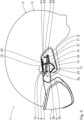
- eine Seitenansicht eines Kopfschutzsystems mit einem Helm, einem Visier und einer Vorrichtung zum Verlagern des Visiers an dem Helm, wobei die Vorrichtung in einer Verschlussstellung angeordnet ist und wobei ein Führungsmittel der Vorrichtung von einem Deckel verdeckt ist,
- Fig. 2
- eine Seitenansicht des Kopfschutzsystems in
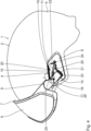
Fig. 1 , wobei der Deckel von der Vorrichtung abgenommen ist, sodass ersichtlich ist, dass das Führungsmittel eine Kulissenführung zum Verlagern des Visiers relativ zu dem Helm aufweist, - Fig. 3
- eine Seitenansicht des Kopfschutzsystems in
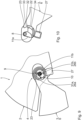
Fig. 1 , wobei die Vorrichtung in einer Transferstellung, zwischen der Verschlussstellung und einer Offenstellung angeordnet ist, - Fig. 4
- eine Seitenansicht des Kopfschutzsystems in
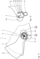
Fig. 1 , wobei die Vorrichtung in der Offenstellung angeordnet ist, - Fig. 5
- eine schematische Darstellung des energetischen Potentials von Antriebskräften und/oder Antriebsmomenten entlang eines Bewegungsverlaufs des Visiers relativ zu dem Helm, welche von mindestens einem Vorspannmittel der Vorrichtung zwischen einem Helmanschlussmittel und einem Visieranschlussmittel der Vorrichtung bewirkt werden,
- Fig. 6
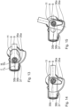
- eine Seitenansicht eines Kopfschutzsystems gemäß einer weiteren Ausführungsform, wobei die Vorrichtung in der Verschlussstellung angeordnet ist und wobei das Führungsmittel zwei Gelenke zum rotatorischen Verlagern des Visiers relativ zu dem Helm um zwei parallel und exzentrisch zueinander angeordnete Drehachsen aufweist,
- Fig. 7
- eine Rückansicht der Vorrichtung in
Fig. 6 , - Fig. 8
- eine Explosionsdarstellung der Vorrichtung in
Fig. 6 , - Fig. 9
- eine Seitenansicht des Kopfschutzsystems in
Fig. 6 , wobei die Vorrichtung in der Transferstellung angeordnet ist, - Fig. 10
- eine Rückansicht der Vorrichtung in
Fig. 9 , - Fig. 11
- eine Seitenansicht des Kopfschutzsystems in
Fig. 6 , wobei die Vorrichtung in der Offenstellung angeordnet ist, - Fig. 12
- eine Rückansicht der Vorrichtung in
Fig. 11 , - Fig. 13
- eine Seitenansicht einer Vorrichtung zum Verlagern eines Visiers an einem Helm gemäß einer weiteren Ausführungsform, wobei die Vorrichtung in der Verschlussstellung angeordnet ist und wobei das Führungsmittel eine Kulissenführung zum Verlagern des Visiers relativ zu dem Helm aufweist und,
- Fig. 14
- eine Seitenansicht der Vorrichtung in
Fig. 13 , wobei die Vorrichtung in der Transferstellung angeordnet ist, und - Fig. 15
- eine Seitenansicht der Vorrichtung in
Fig. 13 , wobei die Vorrichtung in der Offenstellung angeordnet ist. - Anhand der
Fig. 1 bis Fig. 5 ist ein Kopfschutzsystem 1 gemäß einer ersten Ausführungsform beschrieben. Das Kopfschutzsystem 1 weist einen Helm 2 zum Schutz des Kopfs und eine Visier 3 zum Schutz des Gesichts, insbesondere der Augen, auf. Das Visier 3 ist mittels zweier Vorrichtungen 4 verlagerbar an dem Helm angebracht. Die beiden Vorrichtungen 4 sind an dem Helm 2 symmetrisch, insbesondere symmetrisch zu einer parallel zur Blickrichtung des Benutzers orientierten Vertikalebene, vorzugsweise beidseitig, angeordnet. - Der Helm 2 umfasst eine Helmschale 5, einen nicht dargestellten Stoßabsorber und einen nicht dargestellten Kinnriemen.
- Das Visier 3 weist ein sich über beide Augen durchgängig erstreckendes Sichtglas 6 auf. Das Sichtglas 6 ist in einem Visierrahmen 7 gehalten. In der Verschlussstellung, in der das Visier 3 geschlossen ist, ist das Visier 3 hinsichtlich seiner Außenkontur flächenbündig zur Außenkontur des Helms 2, insbesondere der Helmschale 5, angeordnet.
- Die beiden Vorrichtung 4 weisen jeweils ein Helmanschlussmittel 8, ein Visieranschlussmittel 9, ein Führungsmittel 10 und ein einziges Vorspannmittel 11 auf. Das Helmanschlussmittel 8 ist fest, insbesondere dauerhaft, mit dem Helm 2, insbesondere der Helmschale 5, verbunden. Das Visieranschlussmittel 9 ist fest, insbesondere dauerhaft, mit dem Visierrahmen 7 verbunden. Ein Deckel 12 der Vorrichtung 4 überdeckt das Helmanschlussmittel 8 und das Visieranschlussmittel 9 zumindest anteilig und das Führungsmittel 10 vollständig.
- Das Führungsmittel 10, das in den
Fig. 2 bis Fig. 4 weiter im Detail dargestellt ist, ist zum geführten Verlagern des Visieranschlussmittels 9 relativ zu dem Helmanschlussmittel 8 ausgebildet. Das Führungsmittel 10 umfasst eine Kulissenführung mit einer ersten Führungskulisse 13 und einer zweiten Führungskulisse 14. Die beiden Führungskulissen 13, 14 weisen jeweils ein Führungselement 15, 16 und einen verschiebbar darin oder daran gelagerten Führungskörper 17, 18 auf. Das erste Führungselement 15 ist als geradliniger Führungsschlitz, insbesondere in Form eines Langlochs, in dem Helmanschlussmittel 8 ausgebildet. Der erste Führungskörper 17 ist als Bolzen, insbesondere als Zapfen, an dem Visieranschlussmittel 9 ausgebildet. Das zweite Führungselement 16 ist als Führungsrahmen mit einem linearen und einem kreissektorförmigen Abschnitt an dem Helmanschlussmittel 8 ausgebildet. Der zweite Führungskörper 18 ist als riegelförmiger Abschnitt des Visieranschlussmittels 9 ausgebildet, an dem auch der erste Führungskörper 17 angebracht ist. - Das Führungsmittel 10, insbesondere die beiden Führungskulissen 13, 14, sind derart ausgebildet, dass das Visieranschlussmittel 9 relativ zu dem Helmanschlussmittel 8 zwischen der Verschlussstellung und einer Transferstellung geradlinig verschiebbar. Ferner ist das Führungsmittel 10, insbesondere sind die Führungskulissen 13, 14, derart ausgebildet, dass das Visieranschlussmittel 9 relativ zu dem Helmanschlussmittel 8 zwischen der Transferstellung und einer Offenstellung, in der das Visier 3 geöffnet ist, drehbar gelagert ist. Die Transferstellung ist zwischen der Offenstellung und der Verschlussstellung angeordnet. Aus der Transferstellung kann das Visieranschlussmittel 9 relativ zu dem Helmanschlussmittel 8 sowohl geradlinig in Richtung der Verschlussstellung als auch rotatorisch in Richtung der Offenstellung verlagert werden.
- Zwischen der Verschlussstellung und der Transferstellung ist das Visieranschlussmittel 9 relativ zu dem Helmanschlussmittel 8 entlang einer Blickrichtung des Benutzers um eine Führungslänge d in einem Bereich vom 5 mm bis 30 mm, insbesondere von 15 mm bis 25 mm, verlagerbar. Zwischen der Transferstellung und der Offenstellung ist das Visieranschlussmittel 9 relativ zu dem Helmanschlussmittel 8 um einen Führungswinkel α in einem Bereich von 25° bis 90°, insbesondere von 35° bis 60°, schwenkbar.
- Das Führungsmittel 10 weist einen Führungswiderstand 19 auf, welcher insbesondere zum ertastbaren Erfassen der Transferstellung durch den Benutzer ausgebildet ist. Der Führungswiderstand 19 umfasst zwei an dem Helmanschlussmittel 8, insbesondere an dem zweiten Führungselement 16, angeordnete, insbesondere elastisch ausgebildete oder gelagerte, Rastnasen 20, welche mit einem an dem Visieranschlussmittel 9 ausgebildeten Raststeg 21 zusammenwirken. Der Führungswiderstand 19 ist derart ausgebildet, dass zum Verlagern des Visieranschlussmittels 9 relativ zu dem Helmanschlussmittel 8 zwischen der Verschlussstellung und der Transferstellung, insbesondere unmittelbar an die Transferstellung angrenzend, eine Widerstandskraft zu überwinden ist. Hierdurch wird die Transferstellung von dem Benutzer taktil erfassbar gekennzeichnet.
- Zum Begrenzen der Verlagerbarkeit des Visieranschlussmittels 9 relativ zu dem Helmanschlussmittel 8 in der Verschlussstellung weist das Führungsmittel 10 einen ersten Endanschlag 22 auf. Zum Begrenzen der Verlagerbarkeit in der Offenstellung weist das Führungsmittel 10 einen zweiten Endanschlag 23 auf. Beide Endanschläge 22, 23 sind durch die zweite Führungskulisse 14 gebildet.
- Das einzige Vorspannmittel 11 ist in Form einer Zugfeder aus einem gummi-elastischen Material, insbesondere in Form eines Gummibands, ausgebildet. Das Vorspannmittel 11 wirkt zwischen dem Visieranschlussmittel 9 und dem Helmanschlussmittel 8, insbesondere zwischen zwei daran angeordneten Ankerelementen 24, 25. Die von dem Vorspannmittel 11 ausgeübte Vorspannkraft F wirkt zwischen dem ersten Ankerelement 24 und dem zweiten Ankerelement 25.
- Zwischen der Transferstellung und der Offenstellung ist das Visieranschlussmittel 9 relativ zu dem Helmanschlussmittel 8 um eine Drehachse 26 schwenkbar. Die Drehachse 26 ist konzentrisch zu dem ersten Führungskörper 17, insbesondere dem Führungszapfen, und zu dem kreissektorförmigen Abschnitt des zweiten Führungselements 16 angeordnet. Die Vorspannkraft F wirkt exzentrisch zu der Drehachse 26 auf das Visieranschlussmittel 9. Ein Abstand b zwischen dem Vektor der Vorspannkraft F und der Drehachse 26 liegt in einem Bereich von 2 mm bis 20 mm, insbesondere beträgt dieser 5 mm.
- Die Vorspannkraft F bewirkt in der Transferstellung eine Antriebskraft FA zwischen dem Helmanschlussmittel 8 und dem Visieranschlussmittel 9, welche das Visieranschlussmittel 9 in die Verschlussstellung vorspannt, also in die Verschlussstellung überführen möchte. Die Antriebskraft FA weist eine parallel zu der Bewegungsbahn zwischen der Verschlussstellung und der Transferstellung orientierte Kraftkomponente ist. Ferner bewirkt die Vorspannkraft F in der Transferstellung ein Antriebsmoment MA zwischen dem Helmanschlussmittel 8 und dem Visieranschlussmittel 9, welches das Visieranschlussmittel 9 in die Offenstellung vorspannt, also in die Offenstellung überführen möchte. Das Antriebsmoment MA begünstigt eine Drehbewegung aus der Transferstellung in die Offenstellung. Hierdurch wird das in der Transferstellung angeordnete Visieranschlussmittel 9 sowohl in Richtung der Verschlussstellung als auch in Richtung der Offenstellung vorgespannt. In der Transferstellung ist die Vorspannkraft F, insbesondere sind die Antriebskraft FA und das Antriebsmoment MA, maximal.
- Die Funktionsweisen des Kopfschutzsystems 1 und der Vorrichtung 4 sind wie folgt:
Das Kopfschutzsystem 1 ist am Kopf des Benutzers angebracht und das Visier 3 sowie das Visieranschlussmittel 9 befinden sich in der Verschlussstellung. Das Vorspannmittel 11 ist gespannt und erzeugt die Vorspannkraft F. - Zum Verlagern des Visiers 3 in die Offenstellung kann das Visier 3 mit der Hand an dem Visierrahmen 7 gegriffen und nach vorne, insbesondere in Blickrichtung des Benutzers, verlagert werden. Hierbei wird das Visieranschlussmittel 9 entgegen der von dem Vorspannmittel 11 zwischen dem Helmanschlussmittel 8 und dem Visieranschlussmittel 9 bewirkten Antriebskraft FA linear in Richtung der Transferstellung verlagert. Hierbei wird das Visier 3, insbesondere das Visieranschlussmittel 9, an dem Führungsmittel 10, insbesondere entlang der Führungskulissen 13, 14, zwischen der Verschlussstellung und der Transferstellung geradlinig geführt. Vor dem Erreichen der Transferstellung muss die von dem Führungswiderstand 19 bewirkte Widerstandskraft überwunden werden. Hierbei werden die Rastnasen 20 elastisch verformt, bis der Raststeg 21 an den Rastnasen 20 vorbeigleiten kann. Das Visier 3, insbesondere das Visieranschlussmittel 9, befindet sich in der Transferstellung. Die Antriebskraft FK, welche das Visieranschlussmittel 9 in die Verschlussstellung vorspannt, ist maximal. In der Transferstellung liegt die Antriebskraft FK vorzugsweise in einem Bereich von 5 N bis 20 N.
- In der Transferstellung gibt das Führungsmittel 10 eine Schwenkbewegung des Visieranschlussmittels 9 relativ zu dem Helmanschlussmittel 8 um die Drehachse 26 frei. Das von dem Vorspannmittel 11 zwischen dem Helmanschlussmittel 8 und dem Visieranschlussmittel 9 bewirkte Antriebsmoment MA spannt das Visieranschlussmittel 9 in die Offenstellung vor. In der Transferstellung ist das Antriebsmoment MA maximal. Vorzugsweise liegt das Antriebsmoment MA in der Transferstellung in einem Bereich von 0,01 Nm bis 1 Nm, insbesondere von 0,05 Nm bis 0,2 Nm.
- Der Führungswiderstand 19 gewährleistet, dass die Anordnung des Visiers 3 in der Transferstellung von dem Benutzer zuverlässig, insbesondere auch beim Betätigen mit Handschuhen, zuverlässig erfassbar ist. Dadurch, dass das Visieranschlussmittel 9 in der Transferstellung, insbesondere zeitgleich, sowohl in die Verschlussstellung als auch in die Offenstellung vorgespannt ist, ist der Bedienkomfort nochmals verbessert. Insbesondere kann das Verlagern des Visieranschlussmittels 9 zwischen der Verschlussstellung und der Offenstellung über die Transferstellung hinaus besonders zuverlässig und kontinuierlich erfolgen.
- In der
Fig. 5 ist das energetische Potential Φ über der Position x entlang des Bewegungsverlaufs des Visieranschlussmittels 9 relativ zu dem Helmanschlussmittel 8 für die Antriebskraft FA und das Antriebsmoment MA dargestellt. Die Verschlussstellung ist durch die Ziffer I gekennzeichnet, die Transferstellung durch die Ziffer II und die Offenstellung durch die Ziffer III. - In der Verschlussstellung und in der Offenstellung liegt das Visieranschlussmittel 9 an den Endanschlägen 22, 23 an, wodurch das energetische Potential Φ sowohl der Antriebskraft FA als auch des Antriebsmoment MA dort Null beträgt. Zwischen der Verschlussstellung und der Transferstellung kann keine Drehbewegung des Visieranschlussmittels 9 relativ zu dem Helmanschlussmittel 8 in Richtung des Antriebsmoments MA erfolgen, wodurch das damit verbundene energetische Potential Φ Null bleibt. Dasselbe gilt gleichermaßen für das energetische Potential aufgrund der Antriebskraft FA zwischen der Transferstellung und der Offenstellung.
- Aufgrund des Spannens des Vorspannmittels 11 beim Verlagern des Visieranschlussmittels 9 aus der Verschlussstellung in die Transferstellung nimmt das energetische Potential Φ zunächst sprunghaft und dann stetig ansteigend bis zum Erreichen der Transferstellung zu. Zwischen der Transferstellung und der Offenstellung ist die lineare Bewegung in Richtung der Antriebskraft FA blockiert. Das in der Transferstellung maximale Antriebsmoment MA nimmt von der Transferstellung in die Offenstellung stetig ab. Gleiches gilt für das energetische Potential Φ aufgrund des Antriebsmoment MA, wobei dieses energetische Potential in der Offenstellung aufgrund des Endanschlags 23 zu Null wird.
- Aus der
Fig. 5 wird ersichtlich, dass das Vorspannmittel 11 das in der Transferstellung angeordnete Visieranschlussmittel 9 sowohl in Richtung der Offenstellung als auch in Richtung der Verschlussstellung vorspannt. - Anhand der
Fig. 6 bis Fig. 12 ist ein weiteres Ausführungsbeispiel des Kopfschutzes 1, insbesondere der Vorrichtung 4, beschrieben. Im Unterschied zu dem vorstehend beschriebenen Ausführungsbeispiel ist das Visier 3 einteilig, insbesondere einstückig, ausgebildet. Das Visier 3 ist reversibel lösbar mit dem Visieranschlussmittel 9 verbunden. Insbesondere ist das Visieranschlussmittel 9 direkt in eine Ausnehmung des Visiers 3 eingesetzt. Die Vorrichtung 4 weist zwei Vorspannmittel 11a, 11b auf, welche als Drehfedern, insbesondere aus einem Federstahl, ausgebildet sind. Die Vorspannmittel 11a, 11b sind als Spiralfedern ausgebildet. Das Führungsmittel 10 ist zum rein gelenkigen Verbinden des Visieranschlussmittels 9 mit dem Helmanschlussmittel 8 ausgebildet. Das Führungsmittel 10 umfasst also keine Kulissenführung. Ferner weist die Vorrichtung 4 einen Griff 27 zum Verlagern der Vorrichtung 4, insbesondere des Visieranschlussmittels 9, aus der Verschlussstellung in die Transferstellung, insbesondere in die Offenstellung, auf. Der Griff 27 ist einteilig, insbesondere stoffschlüssig, mit dem Deckel 12 ausgebildet. - Das Visieranschlussmittel 9 ist mit dem Helmanschlussmittel 8 über ein Kopplungselement 28 verbunden. Der Deckel 12 mit dem Griff 27 ist mittels eines Befestigungsbolzens 29 und eines Achsbolzens 30 starr mit dem Kopplungselement 28 verbunden. Über den Achsbolzen 30 sind der Deckel 12 und das Kopplungselement 28 um eine erste Drehachse 26a drehbar an dem Helmanschlussmittel 8 gelagert. Das ringförmig ausgebildete Visieranschlussmittel 9 ist an dem Kopplungselement 28 um eine zweite Drehachse 26b drehbar gelagert. Die zweite Drehachse 26b ist parallel zu der ersten Drehachse 26a orientiert. Ein Achsabstand c zwischen den beiden Drehachsen 26a, 26b liegt in einem Bereich von 3 mm bis 15 mm, insbesondere beträgt dieser 5 mm.
- Das Führungsmittel 10 umfasst zwei Gelenke 31a, 31b mit den beiden Drehachsen 26a, 26b und eine Führungseinheit 32. Die Führungseinheit 32 umfasst eine Führungskante 33 und einen Führungskörper 34. Die Führungskante 33 ist durch das Helmanschlussmittel 8 ausgebildet und zum einseitigen Führen des Führungskörpers 34 ausgebildet. Der Führungskörper 34 ist einteilig, insbesondere stoffschlüssig mit dem Visieranschlussmittel 9 verbunden. An den beiden Enden der Führungskante 33 sind Endanschläge 22, 23 ausgebildet.
- Das erste Vorspannmittel 11a bewirkt ein Vorspannmoment M1 und hiermit ein entsprechendes Antriebsmoment MA,1 um die erste Drehachse 26a zwischen dem Helmanschlussmittel 8 und dem Visieranschlussmittel 9, insbesondere dem Kopplungselement 28. Das zweite Vorspannmittel 11b bewirkt ein Vorspannmoment M2 und hiermit ein entsprechendes Antriebsmoment MA,2 um die zweite Drehachse 26b zwischen dem Visieranschlussmittel 9 und dem Helmanschlussmittel 8, insbesondere dem Kopplungselement 28. Das erste Vorspannmoment M1 und das zweite Vorspannmoment M2 sind derart orientiert, dass das Kopplungselement 28 durch beide Antriebsmomente MA,1, MA,2 in die Verschlussstellung vorgespannt ist.
- Die Funktionsweise des Kopfschutzsystems 1 und der Vorrichtung 4 gemäß der vorstehend beschriebenen Ausführungsform ist wie folgt:
Das Visier 3 und die Vorrichtung 4, insbesondere das Visieranschlussmittel 9, befinden sich zunächst in der Verschlussstellung, in welcher der Führungskörper 34 an dem ersten Endanschlag 22 anliegt. Der Griff 27 erstreckt sich von der zweiten Drehachse 26b in horizontaler Richtung. - Zum Verlagern des Visieranschlussmittels 9 in die Transferstellung wird der Griff 27 von dem Benutzer mit der Hand nach unten, insbesondere in eine annähernd vertikale Orientierung, geschwenkt. Hierdurch wird das starr mit dem Griff 27 verbundene Kopplungselement 28 um die erste Drehachse 26a entgegen der Vorspannkraft des ersten Vorspannmittels 11a, insbesondere auch des zweiten Vorspannmittels 11b, geschwenkt. Das gelenkig an dem Kopplungselement 28 angebrachte Visieranschlussmittel 9 wird von dem Kopplungselement 28 mitgenommen. Der an dem Visieranschlussmittel 9 angebrachte Führungskörper 34 ist mittels des zweiten Vorspannmittels 11b an die Führungskante 33 vorgespannt. Der Führungskörper 34 gleitet entlang der Führungskante 33 in die Transferstellung.
- In der Transferstellung bewirkt das erste Vorspannmittel 11a das Antriebsmoment MA,1, welches das Visieranschlussmittel 9 über das Kopplungselement 28 in die Verschlussstellung vorspannt. Ferner bewirkt das zweite Vorspannmittel 11b das Antriebsmoment MA,2, welches das Visieranschlussmittel 9 in die Offenstellung vorspannt.
- Dadurch, dass der Griff 27 in der Transferstellung von dem Benutzer noch gehalten wird, ist eine Rückführung des Visieranschlussmittels 9 in die Verschlussstellung verhindert. Das zweite Vorspannmittel 11b bewirkt das Verlagern des Visieranschlussmittels 9 in die Offenstellung. In der Offenstellung liegt der Führungskörper 34 an dem zweiten Endanschlag 23 an.
- In der Transferstellung ist das energetische Potential Φ einer Verlagerungsbewegung in die Verschlussstellung bzw. in die Offenstellung aufgrund der beiden Antriebsmomente MA,1, MA,2 ungleich Null. In der Verschlussstellung und in der Offenstellung ist das jeweilige energetische Potential Null.
- Anhand der
Fig. 13 bis Fig. 15 ist ein weiteres Ausführungsbeispiel beschrieben. Im Unterschied zu der ersten beschriebenen Ausführungsform ist das Vorspannmittel 11 nicht als Zugfeder, sondern als Biegefeder ausgebildet. Das einzige Vorspannmittel 11 ist einteilig, insbesondere ohne stoffliche Trennung, ausgebildet und umfasst zwei Funktionsabschnitte 35a, 35b. Der erste Funktionsabschnitt 35a bewirkt in der Art einer Druckfeder über zwei Schenkel 36a, 36b eine Vorspannkraft F und hierdurch eine entsprechende Antriebskraft FA zwischen dem Helmanschlussmittel 8 und dem Visieranschlussmittel 9 zum Verlagern des Visieranschlussmittels 9 in die Verschlussstellung. - Der zweite Funktionsabschnitt 35b bewirkt ein Vorspannmoment M und hierdurch ein entsprechendes Antriebsmoment MA zwischen dem Helmanschlussmittel 8 und dem Visieranschlussmittel 9 zum Vorspannen des Visieranschlussmittels 9 in die Offenstellung. In der Transferstellung ist das Visieranschlussmittel 9 mittels des Vorspannmittels 11 sowohl in die Verschlussstellung als auch in die Offenstellung vorgespannt.
- Dadurch, dass das Vorspannmittel 11 einteilig ausgebildet ist, jedoch das bisherige Anschlussmittel 9 sowohl in die Verschlussstellung als auch in die Offenstellung vorspannt und hierzu die Vorspannkraft F als auch das Vorspannmoment M auf das Visieranschlussmittel 9 ausübt, ist die Vorrichtung 4 konstruktiv besonders einfach im Aufbau und wirtschaftlich herstellbar.
- Die Funktionsweise des Kopfschutzsystems 1 und der Vorrichtung 4 entspricht der Funktionsweise des Kopfschutzsystems 1 und der Vorrichtung 4 gemäß den vorstehend beschriebenen Ausführungsformen.
- Den obigen Ausführungsformen ist insbesondere gemeinsam, dass deren Führungsmittel 10 einen Bewegungsverlauf des Visieranschlussmittels 9 relativ zu dem Helmanschlussmittel 8 gewährleistet, welcher in der Transferstellung einen Knick 37 aufweist. Insbesondere hierdurch wird erreicht, dass das Visieranschlussmittel 9 in der Transferstellung sowohl in Richtung der Verschlussstellung als auch in Richtung der Offenstellung vorspannbar ist.
- Das Kopfschutzsystem 1 und die Vorrichtung 4 gewährleisten vorteilhaft, dass das Visier 3 bzw. das jeweilige Visieranschlussmittel 9 relativ zu dem Helm 2 bzw. dem Helmanschlussmittel 8 besonders zuverlässig, kontinuierlich und komfortabel zwischen der Verschlussstellung und der Offenstellung verlagerbar sind. Das Führungsmittel 10 und das Vorspannmittel 11 sind zudem besonders einfach im Aufbau, wodurch die Vorrichtung 4 und das Kopfschutzsystem 1 besonders wirtschaftlich herstellbar sind.
Claims (15)
- Vorrichtung (4), insbesondere Visiermechanismus, zum Verlagern eines Visiers (3) an einem Helm (2), aufweisend1.1. ein Helmanschlussmittel (8) zum Verbinden der Vorrichtung (4) mit dem Helm (2),1.2. ein Visieranschlussmittel (9) zum Verbinden der Vorrichtung (4) mit dem Visier (3), und1.3. ein Führungsmittel (10) zum geführten Verlagern des Visieranschlussmittels (9) relativ zu dem Helmanschlussmittel (8) zwischen1.3.1. einer Verschlussstellung, in der das Visier (3) geschlossen ist,1.3.2. einer Offenstellung, in der das Visier (3) geöffnet ist, und1.3.3. einer Transferstellung, zwischen der Verschlussstellung und der Offenstellung,gekennzeichnet durch1.4. mindestens ein Vorspannmittel (11, 11a, 11b) zum Vorspannen des in der Transferstellung angeordneten Visieranschlussmittels (9) in Richtung der Verschlussstellung und in Richtung der Offenstellung.
- Vorrichtung (4) nach Anspruch 1, gekennzeichnet durch ein einziges Vorspannmittel (11).
- Vorrichtung (4) nach Anspruch 1 oder 2, dadurch gekennzeichnet, dass ein in der Transferstellung von dem mindestens einen Vorspannmittel (11, 11a, 11b) bewirkter resultierender Kraftvektor und/oder Momentenvektor zwischen dem Visieranschlussmittel (9) und dem Helmanschlussmittel (8) in Richtung der Verschlussstellung und in Richtung der Offenstellung ungleich Null ist.
- Vorrichtung (4) nach einem der vorstehenden Ansprüche, dadurch gekennzeichnet, dass in der Transferstellung das mindestens eine Vorspannmittel (11, 11a, 11b) zwischen dem Helmanschlussmittel (8) und dem Visieranschlussmittel (9) eine Antriebskraft (FA) und ein Antriebsmoment (MA) bewirkt.
- Vorrichtung (4) nach einem der vorstehenden Ansprüche, dadurch gekennzeichnet, dass in der Transferstellung ein erstes Vorspannmittel (11a) zwischen dem Helmanschlussmittel (8) und dem Visieranschlussmittel (9) eine erste Antriebskraft (FA) und/oder ein erstes Antriebsmoment (MA, MA,1) in Richtung der Verschlussstellung bewirkt und ein zweites Vorspannmittel (11b) eine zweite Antriebskraft (FA) und/oder ein zweites Antriebsmoment (MA,2) zwischen dem Helmanschlussmittel (8) und dem Visieranschlussmittel (9) in Richtung der Offenstellung bewirkt.
- Vorrichtung (4) nach einem der vorstehenden Ansprüche, gekennzeichnet durch einen Bewegungsverlauf des Visieranschlussmittels (9) relativ zu dem Helmanschlussmittel (8) in der Transferstellung einen Knick (37) aufweist.
- Vorrichtung (4) nach einem der vorstehenden Ansprüche, dadurch gekennzeichnet, dass das Führungsmittel (10) mindestens eine Kulissenführung (13, 14) zum geführten Verlagern des Visieranschlussmittels (9) relativ zu dem Helmanschlussmittel (8) aufweist.
- Vorrichtung (4) nach einem der vorstehenden Ansprüche, dadurch gekennzeichnet, dass das Führungsmittel (10) mindestens ein Gelenk (31a, 31b) zum geführten Verlagern des Visieranschlussmittels (9) relativ zu dem Helmanschlussmittel (8) aufweist.
- Vorrichtung (4) nach einem der vorstehenden Ansprüche, dadurch gekennzeichnet, dass das Führungsmittel (10) derart ausgebildet ist, dass das Visieranschlussmittel (9) beim Verlagern zwischen der Verschlussstellung und der Transferstellung um einen Winkel (α) von maximal 5° relativ zu dem Helmanschlussmittel (8) geschwenkt wird.
- Vorrichtung (4) nach einem der vorstehenden Ansprüche, dadurch gekennzeichnet, dass das Führungsmittel (10) zum rein translatorischen, geradlinigen Verlagern des Visieranschlussmittels (9) relativ zu dem Helmanschlussmittel (8) zwischen der Verschlussstellung und der Transferstellung ausgebildet ist.
- Vorrichtung (4) nach einem der vorstehenden Ansprüche, dadurch gekennzeichnet, dass das Führungsmittel (10) zum Schwenken des Visieranschlussmittels (9) relativ zu dem Helmanschlussmittel (8) zwischen der Transferstellung und der Offenstellung ausgebildet ist.
- Vorrichtung (4) nach einem der vorstehenden Ansprüche, dadurch gekennzeichnet, dass das Führungsmittel (10) zum Schwenken des Visieranschlussmittels (9) relativ zu dem Helmanschlussmittel (8) zwischen der Transferstellung und der Offenstellung um einen Winkel (α) von mindestens 15° ausgebildet ist.
- Vorrichtung (4) nach einem der vorstehenden Ansprüche, gekennzeichnet durch einen Griff (27) zum Verlagern des Visiers (3) zwischen der Verschlussstellung und der Offenstellung.
- Vorrichtung (4) nach Anspruch 13, dadurch gekennzeichnet, dass der Griff (27) relativ zu dem Visieranschlussmittel (9) beweglich gelagert ist.
- Kopfschutzsystem (1), aufweisend15.1. einen Helm (2) und/oder ein Visier (3), und15.2. mindestens eine Vorrichtung (4) nach einem der Ansprüche 1 bis 14, welche mittels des Helmanschlussmittels (8) mit dem Helm (2) verbunden ist und/oder mittels des Visieranschlussmittels (9) mit dem Visier (3) verbunden ist.
Applications Claiming Priority (1)
| Application Number | Priority Date | Filing Date | Title |
|---|---|---|---|
| DE102020211600.8A DE102020211600A1 (de) | 2020-09-16 | 2020-09-16 | Vorrichtung, insbesondere Visiermechanismus, zum Verlagern eines Visiers an einem Helm und Kopfschutzsystem |
Publications (2)
| Publication Number | Publication Date |
|---|---|
| EP3970545A1 EP3970545A1 (de) | 2022-03-23 |
| EP3970545B1 true EP3970545B1 (de) | 2025-04-23 |
Family
ID=77520621
Family Applications (1)
| Application Number | Title | Priority Date | Filing Date |
|---|---|---|---|
| EP21193573.9A Active EP3970545B1 (de) | 2020-09-16 | 2021-08-27 | Vorrichtung, insbesondere visiermechanismus, zum verlagern eines visiers an einem helm und kopfschutzsystem |
Country Status (2)
| Country | Link |
|---|---|
| EP (1) | EP3970545B1 (de) |
| DE (1) | DE102020211600A1 (de) |
Families Citing this family (3)
| Publication number | Priority date | Publication date | Assignee | Title |
|---|---|---|---|---|
| DE102023121097A1 (de) * | 2023-08-08 | 2025-02-13 | ABUS August Bremicker Söhne Kommanditgesellschaft | Schutzhelm |
| AT527624A1 (de) * | 2023-09-28 | 2025-04-15 | Atomic Austria Gmbh | Sporthelmanordnung |
| WO2025146609A1 (en) * | 2024-01-02 | 2025-07-10 | Momo Design Srl | Protection helmet |
Family Cites Families (10)
| Publication number | Priority date | Publication date | Assignee | Title |
|---|---|---|---|---|
| IT8123588U1 (it) | 1981-11-20 | 1983-05-20 | Essepi Srl | Cerniera per visiera ad incasso di caschi protettivi, in particolare per motociclisti. |
| DE9007028U1 (de) | 1990-06-23 | 1990-08-30 | Uvex Winter Optik GmbH, 8510 Fürth | Schutzhelm, insbesondere Motorradschutzhelm |
| US5177816A (en) * | 1991-12-10 | 1993-01-12 | The United States Of America As Represented By The Secretary Of The Navy | Helmet visor support apparatus |
| EP1293138A1 (de) | 2001-09-14 | 2003-03-19 | OPTICOS S.r.l. | Vorrichtung zum Freigeben und Verschwenken des Visiers eines Schutzhelmes für Motorradfahrer |
| NZ568990A (en) * | 2008-06-06 | 2011-02-25 | Pacific Helmets Nz Ltd | Hinge system/visor attachment |
| US8555424B2 (en) * | 2009-03-16 | 2013-10-15 | Danny Higgins | Helmet having a guiding mechanism for a compatible visor |
| CA2767266C (en) | 2012-02-03 | 2015-07-21 | Danny Higgins | Helmet having a guiding mechanism for a compatible visor |
| ITUB20153701A1 (it) | 2015-09-17 | 2017-03-17 | Caberg Spa | Struttura di casco di tipo jet con visiera incorporata |
| FR3046911B1 (fr) | 2016-01-22 | 2018-01-12 | Salomon Sas | Visiere et casque muni d'une telle visiere |
| IT201700021390A1 (it) | 2017-02-24 | 2018-08-24 | Ci Erre E S R L | Casco protettivo con visiera/occhiale ribaltabile. |
-
2020
- 2020-09-16 DE DE102020211600.8A patent/DE102020211600A1/de active Pending
-
2021
- 2021-08-27 EP EP21193573.9A patent/EP3970545B1/de active Active
Also Published As
| Publication number | Publication date |
|---|---|
| DE102020211600A1 (de) | 2022-03-17 |
| EP3970545A1 (de) | 2022-03-23 |
Similar Documents
| Publication | Publication Date | Title |
|---|---|---|
| EP3970545B1 (de) | Vorrichtung, insbesondere visiermechanismus, zum verlagern eines visiers an einem helm und kopfschutzsystem | |
| DE102007003091B3 (de) | Verstellbare Lenksäule für ein Kraftfahrzeug | |
| EP2631116B1 (de) | Kopfstütze | |
| DE29609541U1 (de) | Stanzvorrichtung | |
| DE102007052060A1 (de) | Messer | |
| EP3915829B1 (de) | Fahrzeugsitzbeschlag und fahrzeugsitz | |
| EP2307259A2 (de) | Lenksäule für ein kraftfahrzeug | |
| EP1838561B1 (de) | Höhenverstellbare umlenkvorrichtung für einen dreipunktgurt, fahrzeugsitz mit einem dreipunktgurt sowie verfahren zur höhenverstellung des oberen haltepunktes eines dreipunktgurtes | |
| EP4027824B1 (de) | Visiermechanik für einen schutzhelm | |
| DE102007041521A1 (de) | Kopfstütze für ein Fahrzeug | |
| DE102008008747B4 (de) | Schließsystem | |
| EP3708421B1 (de) | Höhenverstelleinrichtung einer kopfstütze eines kindersitzes | |
| EP2364906B1 (de) | Axiale Sicherung mit integriertem Verschlussstopfen | |
| DE102010045423B4 (de) | Feststellvorrichtung für verstellbare Kraftfahrzeuglenksäule | |
| DE102019200488A1 (de) | Lenksäule für ein Kraftfahrzeug | |
| DE102010044753A1 (de) | Feststellvorrichtung für verstellbare Kraftfahrzeuglenksäule | |
| EP0491908B1 (de) | Einrichtung zur verstellung der vorlage des schaftes eines schischuhes | |
| EP1266816A2 (de) | Verriegelungseinheit für eine einstellbare Lenksäule | |
| EP2373233B1 (de) | Handgriffvorrichtung | |
| DE3205133C2 (de) | ||
| DE102005005826B4 (de) | Kopfstütze | |
| EP3384795B1 (de) | Halterung für brillengläser und helm mit solch einer halterung | |
| EP1932719A1 (de) | Haltevorrichtung für Gepäckstangen | |
| DE102007041495B3 (de) | Kopfstütze für einen Fahrzeugsitz und Antriebseinrichtung | |
| EP1516788B1 (de) | Höhenversteller für den oberen Umlenkbeschlag von Fahrzeug-Sicherheitsgurten |
Legal Events
| Date | Code | Title | Description |
|---|---|---|---|
| PUAI | Public reference made under article 153(3) epc to a published international application that has entered the european phase |
Free format text: ORIGINAL CODE: 0009012 |
|
| STAA | Information on the status of an ep patent application or granted ep patent |
Free format text: STATUS: THE APPLICATION HAS BEEN PUBLISHED |
|
| AK | Designated contracting states |
Kind code of ref document: A1 Designated state(s): AL AT BE BG CH CY CZ DE DK EE ES FI FR GB GR HR HU IE IS IT LI LT LU LV MC MK MT NL NO PL PT RO RS SE SI SK SM TR |
|
| STAA | Information on the status of an ep patent application or granted ep patent |
Free format text: STATUS: REQUEST FOR EXAMINATION WAS MADE |
|
| 17P | Request for examination filed |
Effective date: 20220909 |
|
| RBV | Designated contracting states (corrected) |
Designated state(s): AL AT BE BG CH CY CZ DE DK EE ES FI FR GB GR HR HU IE IS IT LI LT LU LV MC MK MT NL NO PL PT RO RS SE SI SK SM TR |
|
| P01 | Opt-out of the competence of the unified patent court (upc) registered |
Effective date: 20230503 |
|
| STAA | Information on the status of an ep patent application or granted ep patent |
Free format text: STATUS: EXAMINATION IS IN PROGRESS |
|
| 17Q | First examination report despatched |
Effective date: 20231213 |
|
| GRAP | Despatch of communication of intention to grant a patent |
Free format text: ORIGINAL CODE: EPIDOSNIGR1 |
|
| STAA | Information on the status of an ep patent application or granted ep patent |
Free format text: STATUS: GRANT OF PATENT IS INTENDED |
|
| INTG | Intention to grant announced |
Effective date: 20241223 |
|
| GRAS | Grant fee paid |
Free format text: ORIGINAL CODE: EPIDOSNIGR3 |
|
| GRAA | (expected) grant |
Free format text: ORIGINAL CODE: 0009210 |
|
| STAA | Information on the status of an ep patent application or granted ep patent |
Free format text: STATUS: THE PATENT HAS BEEN GRANTED |
|
| AK | Designated contracting states |
Kind code of ref document: B1 Designated state(s): AL AT BE BG CH CY CZ DE DK EE ES FI FR GB GR HR HU IE IS IT LI LT LU LV MC MK MT NL NO PL PT RO RS SE SI SK SM TR |
|
| REG | Reference to a national code |
Ref country code: GB Ref legal event code: FG4D Free format text: NOT ENGLISH |
|
| REG | Reference to a national code |
Ref country code: CH Ref legal event code: EP |
|
| REG | Reference to a national code |
Ref country code: DE Ref legal event code: R096 Ref document number: 502021007268 Country of ref document: DE |
|
| REG | Reference to a national code |
Ref country code: IE Ref legal event code: FG4D Free format text: LANGUAGE OF EP DOCUMENT: GERMAN |
|
| REG | Reference to a national code |
Ref country code: NL Ref legal event code: MP Effective date: 20250423 |
|
| PG25 | Lapsed in a contracting state [announced via postgrant information from national office to epo] |
Ref country code: NL Free format text: LAPSE BECAUSE OF FAILURE TO SUBMIT A TRANSLATION OF THE DESCRIPTION OR TO PAY THE FEE WITHIN THE PRESCRIBED TIME-LIMIT Effective date: 20250423 |
|
| PG25 | Lapsed in a contracting state [announced via postgrant information from national office to epo] |
Ref country code: PT Free format text: LAPSE BECAUSE OF FAILURE TO SUBMIT A TRANSLATION OF THE DESCRIPTION OR TO PAY THE FEE WITHIN THE PRESCRIBED TIME-LIMIT Effective date: 20250825 Ref country code: FI Free format text: LAPSE BECAUSE OF FAILURE TO SUBMIT A TRANSLATION OF THE DESCRIPTION OR TO PAY THE FEE WITHIN THE PRESCRIBED TIME-LIMIT Effective date: 20250423 Ref country code: ES Free format text: LAPSE BECAUSE OF FAILURE TO SUBMIT A TRANSLATION OF THE DESCRIPTION OR TO PAY THE FEE WITHIN THE PRESCRIBED TIME-LIMIT Effective date: 20250423 |
|
| REG | Reference to a national code |
Ref country code: LT Ref legal event code: MG9D |
|
| PG25 | Lapsed in a contracting state [announced via postgrant information from national office to epo] |
Ref country code: GR Free format text: LAPSE BECAUSE OF FAILURE TO SUBMIT A TRANSLATION OF THE DESCRIPTION OR TO PAY THE FEE WITHIN THE PRESCRIBED TIME-LIMIT Effective date: 20250724 Ref country code: NO Free format text: LAPSE BECAUSE OF FAILURE TO SUBMIT A TRANSLATION OF THE DESCRIPTION OR TO PAY THE FEE WITHIN THE PRESCRIBED TIME-LIMIT Effective date: 20250723 |
|
| PG25 | Lapsed in a contracting state [announced via postgrant information from national office to epo] |
Ref country code: PL Free format text: LAPSE BECAUSE OF FAILURE TO SUBMIT A TRANSLATION OF THE DESCRIPTION OR TO PAY THE FEE WITHIN THE PRESCRIBED TIME-LIMIT Effective date: 20250423 |
|
| PGFP | Annual fee paid to national office [announced via postgrant information from national office to epo] |
Ref country code: IT Payment date: 20250829 Year of fee payment: 5 |
|
| PG25 | Lapsed in a contracting state [announced via postgrant information from national office to epo] |
Ref country code: BG Free format text: LAPSE BECAUSE OF FAILURE TO SUBMIT A TRANSLATION OF THE DESCRIPTION OR TO PAY THE FEE WITHIN THE PRESCRIBED TIME-LIMIT Effective date: 20250423 |
|
| PGFP | Annual fee paid to national office [announced via postgrant information from national office to epo] |
Ref country code: GB Payment date: 20250822 Year of fee payment: 5 |
|
| PG25 | Lapsed in a contracting state [announced via postgrant information from national office to epo] |
Ref country code: HR Free format text: LAPSE BECAUSE OF FAILURE TO SUBMIT A TRANSLATION OF THE DESCRIPTION OR TO PAY THE FEE WITHIN THE PRESCRIBED TIME-LIMIT Effective date: 20250423 |
|
| PGFP | Annual fee paid to national office [announced via postgrant information from national office to epo] |
Ref country code: FR Payment date: 20250821 Year of fee payment: 5 Ref country code: AT Payment date: 20251020 Year of fee payment: 5 |
|
| PG25 | Lapsed in a contracting state [announced via postgrant information from national office to epo] |
Ref country code: RS Free format text: LAPSE BECAUSE OF FAILURE TO SUBMIT A TRANSLATION OF THE DESCRIPTION OR TO PAY THE FEE WITHIN THE PRESCRIBED TIME-LIMIT Effective date: 20250723 |
|
| PG25 | Lapsed in a contracting state [announced via postgrant information from national office to epo] |
Ref country code: IS Free format text: LAPSE BECAUSE OF FAILURE TO SUBMIT A TRANSLATION OF THE DESCRIPTION OR TO PAY THE FEE WITHIN THE PRESCRIBED TIME-LIMIT Effective date: 20250823 |
|
| PG25 | Lapsed in a contracting state [announced via postgrant information from national office to epo] |
Ref country code: LV Free format text: LAPSE BECAUSE OF FAILURE TO SUBMIT A TRANSLATION OF THE DESCRIPTION OR TO PAY THE FEE WITHIN THE PRESCRIBED TIME-LIMIT Effective date: 20250423 |