EP3970480B1 - Cage for housing laboratory animals - Google Patents
Cage for housing laboratory animals Download PDFInfo
- Publication number
- EP3970480B1 EP3970480B1 EP21197045.4A EP21197045A EP3970480B1 EP 3970480 B1 EP3970480 B1 EP 3970480B1 EP 21197045 A EP21197045 A EP 21197045A EP 3970480 B1 EP3970480 B1 EP 3970480B1
- Authority
- EP
- European Patent Office
- Prior art keywords
- shaped body
- wall
- cage
- side wall
- box
- Prior art date
- Legal status (The legal status is an assumption and is not a legal conclusion. Google has not performed a legal analysis and makes no representation as to the accuracy of the status listed.)
- Active
Links
Images



Classifications
-
- A—HUMAN NECESSITIES
- A01—AGRICULTURE; FORESTRY; ANIMAL HUSBANDRY; HUNTING; TRAPPING; FISHING
- A01K—ANIMAL HUSBANDRY; AVICULTURE; APICULTURE; PISCICULTURE; FISHING; REARING OR BREEDING ANIMALS, NOT OTHERWISE PROVIDED FOR; NEW BREEDS OF ANIMALS
- A01K1/00—Housing animals; Equipment therefor
- A01K1/02—Pigsties; Dog-kennels; Rabbit-hutches or the like
- A01K1/03—Housing for domestic or laboratory animals
- A01K1/031—Cages for laboratory animals; Cages for measuring metabolism of animals
-
- A—HUMAN NECESSITIES
- A01—AGRICULTURE; FORESTRY; ANIMAL HUSBANDRY; HUNTING; TRAPPING; FISHING
- A01K—ANIMAL HUSBANDRY; AVICULTURE; APICULTURE; PISCICULTURE; FISHING; REARING OR BREEDING ANIMALS, NOT OTHERWISE PROVIDED FOR; NEW BREEDS OF ANIMALS
- A01K1/00—Housing animals; Equipment therefor
- A01K1/02—Pigsties; Dog-kennels; Rabbit-hutches or the like
- A01K1/035—Devices for use in keeping domestic animals, e.g. fittings in housings or dog beds
-
- A—HUMAN NECESSITIES
- A01—AGRICULTURE; FORESTRY; ANIMAL HUSBANDRY; HUNTING; TRAPPING; FISHING
- A01K—ANIMAL HUSBANDRY; AVICULTURE; APICULTURE; PISCICULTURE; FISHING; REARING OR BREEDING ANIMALS, NOT OTHERWISE PROVIDED FOR; NEW BREEDS OF ANIMALS
- A01K1/00—Housing animals; Equipment therefor
- A01K1/06—Devices for fastening animals, e.g. halters, toggles, neck-bars or chain fastenings
- A01K1/0613—Devices for immobilisation or restraint of animals, e.g. chutes
Definitions
- the present invention relates to the field of housing of laboratory animals.
- the present invention relates to a cage for housing laboratory animals, particularly primates, such as apes, monkeys, or the like.
- the present invention relates to a cage of the aforesaid type comprising a porch modified according to an innovative solution to allow access to the inner space of the cage through said porch.
- the present invention relates to a housing cage of the aforesaid type comprising a main body which defines an inner space available to said laboratory animals, wherein said main body comprises a gate switchable to alternately open and close an opening of said main body through which an operator can gain access to said inner space and thus to the animals inside the cage, and wherein said gate, in the position in which it provides access to said inner space, constitutes part of said porch.
- cages comprising a so-called "porch”
- said porch being applied externally to the main body of the cage, the inner space defined by the said main body and that defined by the said porch being in mutual communication to increase the space available for the animals.
- Said porches are thus an enrichment (compared to the cages which do not have them) because they can be used by the animals as seats and/or elevated observation points and/or play spaces and thus significantly contribute to the welfare of the animals.
- EP3643164A1 discloses such a cage, according to the preamble of claim 1.
- the porches of the known type comprise a substantially box-shaped body comprising closed side walls and at least one open wall, said closed walls and said open wall being mutually joined and connected.
- the porch is then externally attached to a side wall (usually the front wall) of the main body of the cage so that the open side wall of the porch coincides with an opening (fitted with a gate) defined by said side (front) wall of the main body.
- a side wall usually the front wall
- the open side wall of the porch coincides with an opening (fitted with a gate) defined by said side (front) wall of the main body.
- the cages with porch of the known type comprise a movable partition arranged inside the main body parallel to said side wall comprising said opening with gate, wherein the animals are at least partially restrained as follows. Firstly, the gate is closed so that the opening which allows access to the porch from inside the main body is closed as well.
- the movable partition is gradually brought closer to said side (front) wall of the main body provided with an opening with gate to equally gradually reduce the space available to the animals, wherein as soon as the desired (at least partial) restraint of the animals is achieved, an operator can proceed with the planned and/or necessary operation.
- the porches of the known type have several drawbacks and/or disadvantages that the applicant intends to overcome or at least reduce by means of the invention described in this application.
- a first drawback is related to the fact that the porches of the known type, once installed, i.e., fixed to the main body of the cage in the manner outlined above, are always a hindrance for the person who needs to access the animal for the common operations of monitoring, administrating drugs or other.
- the operations normally take place by relegating the animal in the front part of the cages by means of said partition (also called an immobilizer) taking care to close the access to the porch through the dedicated gate.
- said partition also called an immobilizer
- the porch is located in this manner between the operator and the animal, preventing access to the animal by the operator who will always have to remove the porch completely to access the animal. Therefore, since access to the animals is required with a given frequency, it can also be seen that the repeated assembly and disassembly of the porch is a negative factor in terms of waste of time.
- a further drawback found in cages with porches of the known type is that the gate of the opening on the front wall of the cage is usually of the translational switchable type, wherein the closing of said gate results in the risk for the animal which could be trapped and possibly injured between the gate and one of the two opposite edges of said opening; in other words, there is the risk of a "guillotine" effect generated by the switching by translation of the gate from the opening to the closing position.
- the cage according to the present invention originates from the general consideration that the drawbacks found in the cages with porches of known type can be effectively overcome or at least reduced achieving the intended purposes by means of a cage the gate of which, once switched to the opening position, forms an integral part of the porch and contributes to confining the inner space defined by the porch.
- a further consideration underlying the present invention is the fact that the drawbacks encountered in cages with porches of known type can be effectively overcome or at least reduced achieving the intended purposes by means of a porch comprising a side wall switchable to a position in which, with the gate in the opening position, it closes the opening of the main body served by said gate and thus replaces said gate.
- the present invention relates to a cage for housing laboratory animals, said cage comprising a main box-shaped body comprising a bottom wall, an upper wall, and a plurality of side walls, said bottom wall, upper wall, and side walls being connected and joined together to define a first inner space available to said laboratory animals, wherein a first side wall of said main box-shaped body comprises a first opening adapted to allow the access to said inner space from the outside by an operator, and wherein said first side wall comprises a gate which is switchable between a first position, in which it substantially closes said first opening, and a second position, in which it at least partially clears said first opening, wherein said cage comprises a secondary box-shaped body consisting of a bottom wall thereof, an upper wall thereof and a plurality of side walls thereof, said bottom wall, upper wall and side walls of said secondary box-shaped body being connected and joined together to define a second
- said gate comprises two doors, each being rotationally switchable, wherein a third side wall of said secondary box-shaped body joined to said first side wall and opposite to said second side wall of said secondary box-shaped body comprises a fourth opening, and wherein the switching of said doors from said first position to said second position results in the closing of said third opening and fourth opening, respectively.
- the side wall of said secondary box-shaped body opposite to said first side wall of said main box-shaped body is switchable and positionable so as to close said second opening of said first wall of said secondary body and said first opening of said first side wall of said main box-shaped body.
- said side wall of said secondary box-shaped body opposite to said first side wall of said main box-shaped body is translationally switchable along parallel guides defined by said bottom wall of said secondary box-shaped body.
- said upper wall of said secondary box-shaped body is switchable between a first closing position, in which it prevents the access to said second inner space by an operator, and a second opening position, in which it allows the access to said second inner space by an operator.
- said upper wall of said secondary box-shaped body is rotationally switchable about a rotation axis parallel to the intersection between the planes on which said bottom wall of said secondary box-shaped body and said first side wall of said main box-shaped body, respectively, lie.
- said upper wall of said secondary box-shaped body is translationally switchable on a plane parallel to said bottom wall.
- said cage comprises an intermediate wall positioned inside said main body and substantially parallel to said first side wall, wherein said intermediate wall is translationally switchable along a direction which is substantially perpendicular to said first side wall of said main box-shaped body.
- said intermediate wall is switchable between a first position, in which it is close to said first side wall of said main box-shaped body, and a second position, in which it is adjacent to the side wall of said main box-shaped body opposite to said first side wall of said main box-shaped body, wherein the translational switching of said intermediate wall from said second position to said first position results in the reduction of the space available to said laboratory animals.
- the side walls of said main box-shaped body are opposed two-by-two, parallel to each other and have dimensions corresponding two-by-two.
- said bottom wall and upper wall of said main box-shaped body are parallel and have corresponding dimensions.
- the side walls of said secondary box-shaped body are opposed two-by-two, parallel to each other, and have dimensions corresponding two-by-two.
- said bottom wall and upper wall of said secondary box-shaped body are parallel and have corresponding dimensions.
- At least said first wall of said main box-shaped body comprises a mesh-shaped portion or a portion comprising tubular elements made of plastic or metal material.
- At least said side wall of said secondary box-shaped body opposite to said first side wall of said main box-shaped body and switchable and positionable so as to close both said second opening of said first wall of said secondary body and said first opening of said first side wall of said main box-shaped body comprises a mesh-shaped portion or a portion including tubular elements made of plastic or metal material.
- the present invention is particularly applied in the field of laboratory animal housing, this being the reason why the present invention is described hereafter with particular reference to its applications in the field of animal housing.
- the possible applications of the present invention are not limited to those described hereafter.
- the present invention finds convenient application in all cases in which it is necessary to optimize access to animals inside a cage with a porch.
- the present invention finds equally advantageous application in the field of housing and/or transporting of pets.
- the cage according to the embodiment of the present invention depicted therein is identified by reference numeral 10 as a whole; as depicted, the cage 10 comprises a substantially box-shaped (parallelepiped-shaped) main body 11 consisting of a bottom wall 12, an upper wall 13, and a plurality of side walls 14, 15, 16, 17, said bottom wall 12, upper wall 13, and side walls 14, 15, 16, 17 being connected and joined together to define a first inner space Si1 available to said laboratory animals, wherein a first (front) side wall 14 of said main box-shaped body 11 comprises a first opening 18 adapted to allow the access to said inner space from the outside by an operator (as well as the access to the porch by the animals in the cage, as shown in the following description), and wherein said first side wall 14 comprises a gate 19 which is switchable between a first position, in which it substantially closes said first opening 18, and a second position, in which it at least partially clears said first opening 18.
- a first (front) side wall 14 of said main box-shaped body 11 comprises a first opening 18
- the cage 10 further comprises a porch comprising a secondary box-shaped (parallelepiped-shaped) body 30, consisting of a bottom wall 31 thereof, a upper wall 32 thereof and a plurality of side walls 33, 34, 35, 36 thereof, said bottom wall 31, upper wall 32 and side walls 33, 34, 35, 36 of said secondary box-shaped body 30 being connected and joined together to define a second inner space Si2, wherein a first (front) side wall 35 of said secondary box-shaped body 30 comprises a second opening 37, the dimensions of which substantially correspond to those of the wall 35; as shown, said secondary box-shaped body 30 is adapted to be externally applied to said first side wall 14 of said main box-shaped body 11 with said second opening 37 at said first opening 18 to allow said laboratory animals, with said gate 19 in said second position (in which it clears the opening 18 of the wall 14), to access from said first inner space Si1 to said second inner space Si2 and vice versa, from said second inner space Si2 to said first inner space Si1.
- the gate 19 comprises two doors or leaves 191 and 192 respectively (or also a single door or leaf 191 according to alternative embodiments), both rotationally switchable, wherein both side walls 34 and 36 respectively, mutually opposite and parallel are "open” or at least each comprise a respective opening 39 and 38 respectively.
- both side walls 34 and 36 respectively, mutually opposite and parallel are "open” or at least each comprise a respective opening 39 and 38 respectively.
- the (plan) dimensions of the walls 34 and 36 respectively substantially correspond to those of the door 191 and of the door 192 respectively, wherein it is apparent that the rotational switching of said doors 191 and 192 from said first position to said second position (as indicated by the arrows and therefore outwards of the body 11 to clear the opening 18) results in the positioning of the doors 191 and 192 at the side wall 36 and of the side wall 34 of the porch 30 respectively, and thus in the closing of the openings 38 and 39 of the wall 36 and the wall 34 respectively.
- the doors 191 and 192 each constitute an integral part of the porch 30, helping to confine the inner space Si2 defined by the porch 30.
- a further peculiarity of the porch 30 according to the present invention is that, as depicted in figures 1 to 3 , the rear wall 33 of the porch 30 is translationally switchable (as shown by the double arrows) and in particular positionable near the front wall 14 of the box-shaped body 11 to close both the opening 37 defined by the front wall 35 of the porch 30 and the opening 18 of the front wall 14 of said main box-shaped body 11.
- the wall 33 translationally switchable (along guides formed in the bottom wall 31 of the porch 30 and not described in detail for the sake of brevity) allows both an easy and effective restraint of animals in the main body 11 and the access to the animals through the porch 30 and thus without the need to remove or disassemble the porch 30 from the main body 11, wherein reference is made to the following description.
- a further feature of the cage according to the present invention is depicted in figures 4 , 5 , 8 , and 9 .
- partition 40 also named immobilizer for reasons that will be apparent in light of the following description
- partition 40 being arranged parallel to the front wall 14 and the rear wall 16 of the body 11, as well as perpendicular to the mutually opposite walls 15 and 17 respectively.
- the partition 40 is translationally switchable along a direction substantially perpendicular to said first front wall 14 between a first position, in which it is near said front wall 14 of said main box-shaped body 11, and a second position, in which it is adjacent to the rear side wall 16 of said main box-shaped body 11 opposite to said first front wall 14 of said main box-shaped body 11, the position in figure 5 being intermediate between the two aforesaid limit stop positions.
- the positioning of the partition or immobilizer 40 near the front wall 14 results in the reduction of space available to the animals, and thus in at least partial immobilization of the animals themselves.
- the rear wall 33 of the porch 30 is repositioned from the end stop position in figure 1 to the end stop position in figure 3 and figures 4 and 6 in which the wall 33 closes both the opening 37 of the porch 30 and the opening 18 of the main body 11, thereby preventing animals from accessing from the body 11 to the porch 30.
- the next step comprises the translational switching of the partition 40 towards the front wall 14 of the body 11 until the partition 40 is positioned near the front wall 14, in particular until the desired degree of animal restraint between the partition 40 and the front wall 14 is achieved.
- the upper wall 32 of the porch or secondary box-shaped body 30 is rotationally switchable between a first closing position, in which it prevents access by an operator to said second inner space Si2, and a second opening position (represented by means of hatching in figure 1 ), in which it allows access to said second inner space Si2 by said operator, wherein the switching of the wall 32 to the opening position further facilitates access to animals (e.g. when at least partially immobilized between partition 40 and wall 14 in the manner described above) by an operator.
- the upper wall 32 is rotationally switchable about a rotation axis R1 parallel to the intersection between the planes on which said bottom wall 31 of said secondary box-shaped body 30 and said first side (front) wall 14 of said main box-shaped body 11 respectively lie.
- the upper wall 32 is rotationally switchable about a rotation axis R2 parallel to the intersection between the planes on which said upper wall 32 of the porch or the box-shape secondary body 30 and respectively said rear wall 33 of said porch or secondary body 30 lies, whereas according to a further alternative embodiment (not shown), the upper wall 32 is translationally switchable on a plane parallel to the bottom wall 31 of the porch or secondary body 30.
- the present invention allows the widest choice of materials and conformations for making the parts of the box-shaped body 11 and the box-shaped body 30.
- at least said rear side wall 33 of said main box-shaped body 30 may comprise at least one mesh-shaped portion or a portion comprising tubular elements made of plastic or metal material.
- each or at least some of the side and bottom walls of the main body 11 and the secondary body or porch 30 may comprise at least one mesh-shaped portion or a portion comprising tubular elements made of plastic or metal material.
- a cage with porch for housing laboratory animals which is designed so that the porch does not constitute a hindrance and/or obstacle to an operator needing gain access to the animals, and thus which does not need to be removed to allow access to the animals by an operator.
- the porch according to the present invention is adapted to be fixed and removed respectively to and from the main body of a cage according to simple and immediate operations which do not require the use of tools, thereby further reducing the risk of injury to animals.
- a cage for housing laboratory animals that comprises an innovative gate the switching of which from opening to the closing position does not generate any risk of entrapment or possible injury for the animal.
Landscapes
- Life Sciences & Earth Sciences (AREA)
- Environmental Sciences (AREA)
- Zoology (AREA)
- Animal Husbandry (AREA)
- Biodiversity & Conservation Biology (AREA)
- Animal Behavior & Ethology (AREA)
- Health & Medical Sciences (AREA)
- Clinical Laboratory Science (AREA)
- General Health & Medical Sciences (AREA)
- Housing For Livestock And Birds (AREA)
- Catching Or Destruction (AREA)
Description
- The present invention relates to the field of housing of laboratory animals. In particular, the present invention relates to a cage for housing laboratory animals, particularly primates, such as apes, monkeys, or the like. In detail, the present invention relates to a cage of the aforesaid type comprising a porch modified according to an innovative solution to allow access to the inner space of the cage through said porch. In yet greater detail, the present invention relates to a housing cage of the aforesaid type comprising a main body which defines an inner space available to said laboratory animals, wherein said main body comprises a gate switchable to alternately open and close an opening of said main body through which an operator can gain access to said inner space and thus to the animals inside the cage, and wherein said gate, in the position in which it provides access to said inner space, constitutes part of said porch.
- The use of cages comprising a so-called "porch" is widespread today for the housing of laboratory animals, in particular of laboratory primates, e.g., such as monkeys or the like, said porch being applied externally to the main body of the cage, the inner space defined by the said main body and that defined by the said porch being in mutual communication to increase the space available for the animals.
- Said porches are thus an enrichment (compared to the cages which do not have them) because they can be used by the animals as seats and/or elevated observation points and/or play spaces and thus significantly contribute to the welfare of the animals.
EP3643164A1 discloses such a cage, according to the preamble ofclaim 1. - In practice, the porches of the known type comprise a substantially box-shaped body comprising closed side walls and at least one open wall, said closed walls and said open wall being mutually joined and connected.
- The porch is then externally attached to a side wall (usually the front wall) of the main body of the cage so that the open side wall of the porch coincides with an opening (fitted with a gate) defined by said side (front) wall of the main body. Furthermore, it is worth noting that the housing of animals requires the periodic care of the animals themselves which, to be subjected to operations, such as injections, administration of drugs and/or feeding or the like, must be at least partially restrained inside the cage.
- For this purpose, the cages with porch of the known type comprise a movable partition arranged inside the main body parallel to said side wall comprising said opening with gate, wherein the animals are at least partially restrained as follows. Firstly, the gate is closed so that the opening which allows access to the porch from inside the main body is closed as well.
- Then, the movable partition is gradually brought closer to said side (front) wall of the main body provided with an opening with gate to equally gradually reduce the space available to the animals, wherein as soon as the desired (at least partial) restraint of the animals is achieved, an operator can proceed with the planned and/or necessary operation.
- However, although appreciable from many points of view, e.g., the simplicity of construction and/or of application and removal respectively to and from the main body of the cage, the porches of the known type have several drawbacks and/or disadvantages that the applicant intends to overcome or at least reduce by means of the invention described in this application.
- A first drawback is related to the fact that the porches of the known type, once installed, i.e., fixed to the main body of the cage in the manner outlined above, are always a hindrance for the person who needs to access the animal for the common operations of monitoring, administrating drugs or other.
- Indeed, as described above, the operations normally take place by relegating the animal in the front part of the cages by means of said partition (also called an immobilizer) taking care to close the access to the porch through the dedicated gate. It is thus apparent that the porch is located in this manner between the operator and the animal, preventing access to the animal by the operator who will always have to remove the porch completely to access the animal. Therefore, since access to the animals is required with a given frequency, it can also be seen that the repeated assembly and disassembly of the porch is a negative factor in terms of waste of time.
- A further drawback found in cages with porches of the known type is that the gate of the opening on the front wall of the cage is usually of the translational switchable type, wherein the closing of said gate results in the risk for the animal which could be trapped and possibly injured between the gate and one of the two opposite edges of said opening; in other words, there is the risk of a "guillotine" effect generated by the switching by translation of the gate from the opening to the closing position.
- It is the main object of the present invention to overcome or at least reduce or minimize the aforesaid drawbacks found in the cage with porch according to the prior art.
- In particular, it is a first object of the present invention to provide a cage with porch for housing laboratory animals designed so that the porch does not constitute a hindrance and/or obstacle to an operator needing to gain access to the animals, and thus which does not need to be removed to allow access to the animals by an operator.
- It is a further object of the present invention to suggest a porch adapted to be fixed and removed respectively to and from the main body of a cage according to simple and immediate operations which do not require the use of tools, thereby further reducing the risk of injury to animals.
- In particular, it is one of the objects of the present invention to make available a cage for housing laboratory animals comprising an innovative gate the switching of which from opening to the closing position does not generate any risk of entrapment or possible injury for the animal.
- The cage according to the present invention originates from the general consideration that the drawbacks found in the cages with porches of known type can be effectively overcome or at least reduced achieving the intended purposes by means of a cage the gate of which, once switched to the opening position, forms an integral part of the porch and contributes to confining the inner space defined by the porch.
- Furthermore, a further consideration underlying the present invention is the fact that the drawbacks encountered in cages with porches of known type can be effectively overcome or at least reduced achieving the intended purposes by means of a porch comprising a side wall switchable to a position in which, with the gate in the opening position, it closes the opening of the main body served by said gate and thus replaces said gate.
- To overcome or at least reduce the drawbacks found in the cages with porch according to the prior art and based on the considerations provided above, the present invention according to
claim 1 relates to a cage for housing laboratory animals, said cage comprising a main box-shaped body comprising a bottom wall, an upper wall, and a plurality of side walls, said bottom wall, upper wall, and side walls being connected and joined together to define a first inner space available to said laboratory animals, wherein a first side wall of said main box-shaped body comprises a first opening adapted to allow the access to said inner space from the outside by an operator, and wherein said first side wall comprises a gate which is switchable between a first position, in which it substantially closes said first opening, and a second position, in which it at least partially clears said first opening, wherein said cage comprises a secondary box-shaped body consisting of a bottom wall thereof, an upper wall thereof and a plurality of side walls thereof, said bottom wall, upper wall and side walls of said secondary box-shaped body being connected and joined together to define a second inner space, wherein a first own side wall of said secondary box-shaped body comprises a second opening, said secondary box-shaped body being adapted to be externally applied to said first side wall of said main box-shaped body with said second opening at said first opening to allow said laboratory animals, with said gate in said second position, to access from said first inner space to said second inner space and vice versa, from said second inner space to said first inner space; wherein said gate comprises a rotationally switchable door, wherein a second side wall of said secondary box-shaped body joined to said first side wall of said secondary box-shaped body comprises a third opening, and wherein the switching of said door from said first position to said second position results in the closing of said third opening. - According to an embodiment, said gate comprises two doors, each being rotationally switchable, wherein a third side wall of said secondary box-shaped body joined to said first side wall and opposite to said second side wall of said secondary box-shaped body comprises a fourth opening, and wherein the switching of said doors from said first position to said second position results in the closing of said third opening and fourth opening, respectively.
- According to an embodiment, the side wall of said secondary box-shaped body opposite to said first side wall of said main box-shaped body is switchable and positionable so as to close said second opening of said first wall of said secondary body and said first opening of said first side wall of said main box-shaped body.
- According to an embodiment, said side wall of said secondary box-shaped body opposite to said first side wall of said main box-shaped body is translationally switchable along parallel guides defined by said bottom wall of said secondary box-shaped body.
- According to an embodiment, said upper wall of said secondary box-shaped body is switchable between a first closing position, in which it prevents the access to said second inner space by an operator, and a second opening position, in which it allows the access to said second inner space by an operator.
- According to an embodiment, said upper wall of said secondary box-shaped body is rotationally switchable about a rotation axis parallel to the intersection between the planes on which said bottom wall of said secondary box-shaped body and said first side wall of said main box-shaped body, respectively, lie.
- According to an embodiment, said upper wall of said secondary box-shaped body is translationally switchable on a plane parallel to said bottom wall.
- According to an embodiment, said cage comprises an intermediate wall positioned inside said main body and substantially parallel to said first side wall, wherein said intermediate wall is translationally switchable along a direction which is substantially perpendicular to said first side wall of said main box-shaped body.
- According to an embodiment, said intermediate wall is switchable between a first position, in which it is close to said first side wall of said main box-shaped body, and a second position, in which it is adjacent to the side wall of said main box-shaped body opposite to said first side wall of said main box-shaped body, wherein the translational switching of said intermediate wall from said second position to said first position results in the reduction of the space available to said laboratory animals.
- According to an embodiment, the side walls of said main box-shaped body are opposed two-by-two, parallel to each other and have dimensions corresponding two-by-two.
- According to an embodiment, said bottom wall and upper wall of said main box-shaped body are parallel and have corresponding dimensions.
- According to an embodiment, the side walls of said secondary box-shaped body are opposed two-by-two, parallel to each other, and have dimensions corresponding two-by-two.
- According to an embodiment, said bottom wall and upper wall of said secondary box-shaped body are parallel and have corresponding dimensions.
- According to an embodiment, at least said first wall of said main box-shaped body comprises a mesh-shaped portion or a portion comprising tubular elements made of plastic or metal material.
- According to an embodiment, at least said side wall of said secondary box-shaped body opposite to said first side wall of said main box-shaped body and switchable and positionable so as to close both said second opening of said first wall of said secondary body and said first opening of said first side wall of said main box-shaped body comprises a mesh-shaped portion or a portion including tubular elements made of plastic or metal material.
- Further possible embodiments of the present invention are defined in the claims.
- In the following, the present invention will be further explained by means of the following detailed description of its embodiments as depicted in the drawings, in which corresponding or equivalent features and/or component parts of the present invention are identified by the same reference numerals. It must be noted that the present invention is not limited to the embodiments described in the following and depicted in the accompanying drawings; on the contrary, all the variants of and/or changes to the embodiments described hereafter and depicted in the accompanying drawings which will appear obvious and immediate to a person skilled in the art fall within the scope of the present invention.
- In the drawings:
-
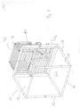
Figure 1 shows a perspective view of a porch for cages according to an embodiment of the present invention with the rear wall in a rearward end stop position; -
Figure 2 shows a perspective view of porch for cages according to an embodiment of the present invention with the rear wall in an intermediate position; -
Figure 3 shows a perspective view of a porch for cages according to an embodiment of the present invention with the rear wall in the forward end stop position; -
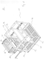
Figure 4 shows a perspective front view of a cage with porch according to an embodiment of the present invention; -
Figure 5 shows a perspective rear view of a cage with porch according to an embodiment of the present invention; -
Figure 6 shows a perspective front view of a cage with porch according to an embodiment of the present invention; -
Figure 7 shows a perspective rear view of a cage with porch according to an embodiment of the present invention; -
Figure 8 shows a perspective front view of a cage with porch according to an embodiment of the present invention; -
Figure 9 shows a perspective rear view of a cage with porch according to an embodiment of the present invention. - The present invention is particularly applied in the field of laboratory animal housing, this being the reason why the present invention is described hereafter with particular reference to its applications in the field of animal housing.
- However, it is worth specifying that the possible applications of the present invention are not limited to those described hereafter. On the contrary, the present invention finds convenient application in all cases in which it is necessary to optimize access to animals inside a cage with a porch. For example, the present invention finds equally advantageous application in the field of housing and/or transporting of pets. In the figures, the cage according to the embodiment of the present invention depicted therein is identified by
reference numeral 10 as a whole; as depicted, thecage 10 comprises a substantially box-shaped (parallelepiped-shaped)main body 11 consisting of abottom wall 12, anupper wall 13, and a plurality ofside walls bottom wall 12,upper wall 13, andside walls side wall 14 of said main box-shaped body 11 comprises afirst opening 18 adapted to allow the access to said inner space from the outside by an operator (as well as the access to the porch by the animals in the cage, as shown in the following description), and wherein saidfirst side wall 14 comprises agate 19 which is switchable between a first position, in which it substantially closes said first opening 18, and a second position, in which it at least partially clears said first opening 18. Thecage 10 further comprises a porch comprising a secondary box-shaped (parallelepiped-shaped)body 30, consisting of abottom wall 31 thereof, aupper wall 32 thereof and a plurality ofside walls bottom wall 31,upper wall 32 andside walls shaped body 30 being connected and joined together to define a second inner space Si2, wherein a first (front)side wall 35 of said secondary box-shaped body 30 comprises asecond opening 37, the dimensions of which substantially correspond to those of thewall 35; as shown, said secondary box-shaped body 30 is adapted to be externally applied to saidfirst side wall 14 of said main box-shaped body 11 with saidsecond opening 37 at said first opening 18 to allow said laboratory animals, with saidgate 19 in said second position (in which it clears the opening 18 of the wall 14), to access from said first inner space Si1 to said second inner space Si2 and vice versa, from said second inner space Si2 to said first inner space Si1. - As further shown, the
gate 19 comprises two doors orleaves leaf 191 according to alternative embodiments), both rotationally switchable, wherein bothside walls respective opening gate 19 comprises a single door or leaf, only one of thewalls - The (plan) dimensions of the
walls door 191 and of thedoor 192 respectively, wherein it is apparent that the rotational switching of saiddoors body 11 to clear the opening 18) results in the positioning of thedoors side wall 36 and of theside wall 34 of theporch 30 respectively, and thus in the closing of theopenings wall 36 and thewall 34 respectively. Once switched to the opening position, thedoors porch 30, helping to confine the inner space Si2 defined by theporch 30. - A further peculiarity of the
porch 30 according to the present invention is that, as depicted infigures 1 to 3 , therear wall 33 of theporch 30 is translationally switchable (as shown by the double arrows) and in particular positionable near thefront wall 14 of the box-shapedbody 11 to close both theopening 37 defined by thefront wall 35 of theporch 30 and theopening 18 of thefront wall 14 of said main box-shapedbody 11. - The
wall 33 translationally switchable (along guides formed in thebottom wall 31 of theporch 30 and not described in detail for the sake of brevity) allows both an easy and effective restraint of animals in themain body 11 and the access to the animals through theporch 30 and thus without the need to remove or disassemble theporch 30 from themain body 11, wherein reference is made to the following description. A further feature of the cage according to the present invention is depicted infigures 4 ,5 ,8 , and9 . - As depicted, there is an intermediate wall or partition 40 (also named immobilizer for reasons that will be apparent in light of the following description) inside the box-shaped
body 11, saidpartition 40 being arranged parallel to thefront wall 14 and therear wall 16 of thebody 11, as well as perpendicular to the mutuallyopposite walls partition 40, as indicated by the double arrow, is translationally switchable along a direction substantially perpendicular to said firstfront wall 14 between a first position, in which it is near saidfront wall 14 of said main box-shapedbody 11, and a second position, in which it is adjacent to therear side wall 16 of said main box-shapedbody 11 opposite to said firstfront wall 14 of said main box-shapedbody 11, the position infigure 5 being intermediate between the two aforesaid limit stop positions. - Therefore, it can be inferred that the positioning of the partition or
immobilizer 40 near thefront wall 14 results in the reduction of space available to the animals, and thus in at least partial immobilization of the animals themselves. - The access to the animals by an operator from outside the
cage 10, e.g., for administering drugs or similar operations can be summarized as follows. - Firstly, the
rear wall 33 of theporch 30 is repositioned from the end stop position infigure 1 to the end stop position infigure 3 andfigures 4 and6 in which thewall 33 closes both theopening 37 of theporch 30 and theopening 18 of themain body 11, thereby preventing animals from accessing from thebody 11 to theporch 30. The next step comprises the translational switching of thepartition 40 towards thefront wall 14 of thebody 11 until thepartition 40 is positioned near thefront wall 14, in particular until the desired degree of animal restraint between thepartition 40 and thefront wall 14 is achieved. - At this point, an operator can access the animals through the space Si2 defined by the
porch 30, in particular through theopening 37, and thus with no need to remove theporch 30 from themain body 11. - Further peculiarities of the porch according to the present invention are depicted in the figures and relate to the fact that, as shown and indicated by the double arrow in
figure 1 , theupper wall 32 of the porch or secondary box-shapedbody 30 is rotationally switchable between a first closing position, in which it prevents access by an operator to said second inner space Si2, and a second opening position (represented by means of hatching infigure 1 ), in which it allows access to said second inner space Si2 by said operator, wherein the switching of thewall 32 to the opening position further facilitates access to animals (e.g. when at least partially immobilized betweenpartition 40 andwall 14 in the manner described above) by an operator. - According to the embodiment shown, the
upper wall 32 is rotationally switchable about a rotation axis R1 parallel to the intersection between the planes on which saidbottom wall 31 of said secondary box-shapedbody 30 and said first side (front)wall 14 of said main box-shapedbody 11 respectively lie. - On the other hand, according to an alternative embodiment (not shown), the
upper wall 32 is rotationally switchable about a rotation axis R2 parallel to the intersection between the planes on which saidupper wall 32 of the porch or the box-shapesecondary body 30 and respectively saidrear wall 33 of said porch orsecondary body 30 lies, whereas according to a further alternative embodiment (not shown), theupper wall 32 is translationally switchable on a plane parallel to thebottom wall 31 of the porch orsecondary body 30. - The present invention allows the widest choice of materials and conformations for making the parts of the box-shaped
body 11 and the box-shapedbody 30. For example, at least saidrear side wall 33 of said main box-shapedbody 30 may comprise at least one mesh-shaped portion or a portion comprising tubular elements made of plastic or metal material. Similarly, each or at least some of the side and bottom walls of themain body 11 and the secondary body orporch 30 may comprise at least one mesh-shaped portion or a portion comprising tubular elements made of plastic or metal material. - It has thus been demonstrated by means of the detailed description given above of the embodiments of the present invention as depicted in the drawings that the present invention makes it possible to obtain the desired results and to overcome or at least limit the drawbacks affecting the prior art.
- In particular, by means of the present invention, a cage with porch for housing laboratory animals is provided which is designed so that the porch does not constitute a hindrance and/or obstacle to an operator needing gain access to the animals, and thus which does not need to be removed to allow access to the animals by an operator.
- Furthermore, the porch according to the present invention is adapted to be fixed and removed respectively to and from the main body of a cage according to simple and immediate operations which do not require the use of tools, thereby further reducing the risk of injury to animals.
- Finally, by means of the present invention, a cage for housing laboratory animals is provided that comprises an innovative gate the switching of which from opening to the closing position does not generate any risk of entrapment or possible injury for the animal.
- Although the present invention is explained above by means of a detailed description of the embodiments thereof as depicted in the drawings the present invention is obviously not limited to the embodiments described above and depicted in the drawings; on the contrary, all the variants and/or changes to the embodiments described and depicted in the accompanying drawings which will be apparent and immediate to a person skilled in the art fall within the scope.
- The scope of protection of the present invention is thus defined by the claims.
Claims (15)
- A cage (10) for housing laboratory animals, said cage comprising a main box-shaped body (11) consisting of a bottom wall (12), an upper wall (13) and a plurality of side walls (14, 15, 16, 17), said bottom wall (12), upper wall (13) and side walls (14, 15, 16, 17) being connected and joined together to define a first inner space (Si1) available to said laboratory animals, wherein a first side wall (14) of said main box-shaped body (11) comprises a first opening (18) adapted to allow the access to said inner space from the outside by an operator, and wherein said first side wall (14) comprises a gate (19) which is switchable between a first position, in which it substantially closes said first opening (18), and a second position, in which it at least partially clears said first opening (18), wherein said cage (10) comprises a secondary box-shaped body (30) consisting of a bottom own wall (31) thereof, an upper own wall (32) thereof and a plurality of own side walls (33, 34, 35, 36) thereof, said own bottom wall (31), upper wall (32) and side walls (33, 34, 35, 36) of said secondary box-shaped body (30) being connected and joined together to define a second inner space (Si2), wherein a first own side wall (35) of said secondary box-shaped body (30) comprises a second opening (37), said secondary box-shaped body (30) being adapted to be externally applied to said first side wall (14) of said main box-shaped body (11) with said second opening (37) positioned at said first opening (18) so as to allow said laboratory animals, with said gate (19) in said second position, to access from said first inner space to said second inner space and vice versa, from said second inner space to said first inner space; wherein said gate (19) comprises a door (191) which is rotationally switchable, characterized in that a second own side wall (36) of said secondary box-shaped body (30) joined to said first own side wall (35) of said secondary box-shaped body (30) comprises a third opening (38), and in that the switching of said door (191) from said first position to said second position results in the closing of said third opening (38).
- A cage (10) according to claim 1, characterized in that said gate (19) comprises two doors (191, 192), each being rotationally switchable, in that a third own side wall (34) of said secondary box-shaped body (30) joined to said first side wall (35) and opposite to said second side wall (36) of said secondary box-shaped body (30) comprises a fourth opening (39), and in that the switching of said doors (191, 192) from said first position to said second position results in the closing of said third opening (38) and fourth opening (39), respectively.
- A cage (10) according to claim 1 or 2, characterized in that the own side wall (33) of said secondary box-shaped body (30) opposite to said first side wall (35) of said secondary box-shaped body (30) is switchable and positionable so as to close both said second opening (37) of said own first wall (35) of said secondary box-shaped body (30) and said first opening (18) of said first side wall (14) of said main box-shaped body (11).
- A cage (10) according to claim 3, characterized in that said own side wall (33) of said secondary box-shaped body (30) opposite to said first side wall (35) of said secondary box-shaped body (30) is translationally switchable along parallel guides defined by said own bottom wall (31) of said secondary box-shaped body (30).
- A cage (10) according to one of claims 1 to 4, characterized in that said own upper wall (32) of said secondary box-shaped body (30) is switchable between a first closed position, in which it prevents the access to said second inner space (Si2) by an operator, and a second open position, in which it allows the access to said second inner space (Si2) by an operator.
- A cage (10) according to claim 5, characterized in that the own upper wall (32) of said secondary box-shaped body (30) is rotationally switchable about a rotation axis (R1) parallel to the intersection between the planes on which said own bottom wall (31) of said secondary box-shaped body (30) and said first side wall (14) of said main box-shaped body (11), respectively, lie.
- A cage (10) according to claim 5, characterized in that said own upper wall (32) of said secondary box-shaped body (30) is translationally switchable on a plane parallel to said own bottom wall (31) of said box-shaped secondary body (30).
- A cage (10) according to one of claims 1 to 7, characterized in that said cage comprises an intermediate wall (40) positioned inside said main body (11) and substantially parallel to said first side wall (14), and in that said intermediate wall (40) is translationally switchable along a direction which is substantially perpendicular to said first side wall (14) of said main box-shaped body (11).
- A cage (10) according to the preceding claim 8, characterized in that said intermediate wall (40) is switchable between a first position, in which it is close to said first side wall (14) of said main box-shaped body (11), and a second position, in which it is adjacent to the side wall (16) of said main box-shaped body (11) opposite to said first side wall (14) of said main box-shaped body (11), and in that the translational switching of said intermediate wall (40) from said second position to said first position results in the reduction of the space available to said laboratory animals.
- A cage according to one of claims 1 to 9, characterized in that the side walls (14, 15, 16, 17) of said main box-shaped body (11) are opposite and parallel two by two and have two-by-two corresponding dimensions.
- A cage according to one of claims 1 to 10, characterized in that said bottom wall (12) and upper wall (13) of said main box-shaped body (11) are parallel and have corresponding dimensions.
- A cage according to one of claims 1 to 11, characterized in that the own side walls (33, 34, 35, 36) of said secondary box-shaped body (30) are opposite and parallel two by two and have two-by-two corresponding dimensions.
- A cage according to one of claims 1 to 12, characterized in that said own bottom wall (31) and own upper wall (32) of said secondary box-shaped body (30) are parallel and have corresponding dimensions.
- A cage according to one of claims 1 to 13, characterized in that at least said first wall (14) of said main box-shaped body (11) comprises a mesh-shaped portion or a portion including tubular elements and made of plastic or metal material.
- A cage (10) according to one of claims 1 to 14, characterized in that at least said own side wall (33) of said secondary box-shaped body (30) which is opposite to said first side wall (35) of said secondary box-shaped body (30) and switchable and positionable so as to close both said second opening (37) of said first own wall (35) of said secondary box-shaped body (30) and said first opening (18) of said first side wall (14) of said main box-shaped body (11) comprises a mesh-shaped portion or a portion including tubular elements and made of plastic or metal material.
Applications Claiming Priority (1)
| Application Number | Priority Date | Filing Date | Title |
|---|---|---|---|
| IT102020000022057A IT202000022057A1 (en) | 2020-09-18 | 2020-09-18 | CAGE OR CAGE FOR LAYING LABORATORY ANIMALS |
Publications (2)
| Publication Number | Publication Date |
|---|---|
| EP3970480A1 EP3970480A1 (en) | 2022-03-23 |
| EP3970480B1 true EP3970480B1 (en) | 2023-03-29 |
Family
ID=73643243
Family Applications (1)
| Application Number | Title | Priority Date | Filing Date |
|---|---|---|---|
| EP21197045.4A Active EP3970480B1 (en) | 2020-09-18 | 2021-09-16 | Cage for housing laboratory animals |
Country Status (5)
| Country | Link |
|---|---|
| US (1) | US11653622B2 (en) |
| EP (1) | EP3970480B1 (en) |
| CN (1) | CN114190283A (en) |
| CA (1) | CA3130949A1 (en) |
| IT (1) | IT202000022057A1 (en) |
Families Citing this family (1)
| Publication number | Priority date | Publication date | Assignee | Title |
|---|---|---|---|---|
| CN116548326B (en) * | 2023-07-10 | 2023-09-29 | 苏州莱奥生物技术有限公司 | Animal test cage convenient to clearance surface attachment |
Family Cites Families (9)
| Publication number | Priority date | Publication date | Assignee | Title |
|---|---|---|---|---|
| US1487789A (en) * | 1922-11-21 | 1924-03-25 | Andrew B Mcbride | Movable partition |
| CH596750A5 (en) * | 1975-05-09 | 1978-03-15 | Heinkel Apparatebau Gmbh & Co | Cage for housing research animals |
| US5036796A (en) * | 1989-11-24 | 1991-08-06 | Monsieur Acier Inoxydable Inc. | Small animal cage |
| JP6029069B2 (en) * | 2013-06-04 | 2016-11-24 | 国立研究開発法人理化学研究所 | Animal experiment equipment |
| CN105532490B (en) * | 2016-02-03 | 2019-03-19 | 中国科学院昆明动物研究所 | The multi-functional non-human primate cognitive function test cage of touch screen |
| CN205813129U (en) * | 2016-05-30 | 2016-12-21 | 广西玮美生物科技有限公司 | The transhipment cage of primate laboratory animal |
| CN109303006A (en) * | 2017-12-14 | 2019-02-05 | 上海浦灵生物科技有限公司 | A kind of novel multi-functional monkey cage for being easy to grab and shift animal |
| CN207653252U (en) * | 2017-12-23 | 2018-07-27 | 内蒙古医科大学 | A kind of mouse catharsis experimental cage |
| US11172648B2 (en) * | 2018-10-24 | 2021-11-16 | Bioculture Mauritius, Ltd. | Non-human primate restraint system |
-
2020
- 2020-09-18 IT IT102020000022057A patent/IT202000022057A1/en unknown
-
2021
- 2021-09-15 US US17/475,858 patent/US11653622B2/en active Active
- 2021-09-15 CA CA3130949A patent/CA3130949A1/en active Pending
- 2021-09-16 EP EP21197045.4A patent/EP3970480B1/en active Active
- 2021-09-17 CN CN202111095266.5A patent/CN114190283A/en active Pending
Also Published As
| Publication number | Publication date |
|---|---|
| IT202000022057A1 (en) | 2022-03-18 |
| US20220087214A1 (en) | 2022-03-24 |
| CN114190283A (en) | 2022-03-18 |
| CA3130949A1 (en) | 2022-03-18 |
| EP3970480A1 (en) | 2022-03-23 |
| US11653622B2 (en) | 2023-05-23 |
Similar Documents
| Publication | Publication Date | Title |
|---|---|---|
| EP3970480A1 (en) | Cage for housing laboratory animals | |
| DE3853802T2 (en) | Doors for pets. | |
| DE69226661T2 (en) | Container for magnetic tape cassette | |
| DE3447589C2 (en) | ||
| US20070204514A1 (en) | Tunnel/wall unit | |
| RU2769877C1 (en) | Expandable modular frame for pet cage formation | |
| DE10322977B4 (en) | A vehicle body structure | |
| EP2368422B1 (en) | Plant protection device | |
| ES2225637T3 (en) | FIXING ELEMENT OF ROLL FOR PASSENGERS FOR PASSENGERS. | |
| DE112017005018T5 (en) | Opening and closing device | |
| US5950566A (en) | Multi-directional telescoping restraining cage for animals | |
| DE69516837T2 (en) | One-way clutch with flexible spring element | |
| ES2333590T5 (en) | Gear mechanism, in particular recessed gear mechanism for a window or the like | |
| US3803668A (en) | Incorporated hinge with stop and removable lock pin | |
| US5372092A (en) | Cow and calf catcher and hauler assembly | |
| DE19855686A1 (en) | Vehicle lamp with composite reflector | |
| EP0350558B1 (en) | Milking device for cows and buffalo-cows with comb-like arrangement of the stations. | |
| EP4343123B1 (en) | Silencer | |
| DE202006019690U1 (en) | Air passage device | |
| ES2143451T3 (en) | DEVICE FOR CLOSING AN OPENING OF THE WALL. | |
| EP1611393A1 (en) | Garden extrusion | |
| DE2301366A1 (en) | COLD CELL | |
| EP1063405B1 (en) | Housing for a load control device | |
| EP0939238A2 (en) | Flexible shaft coupling | |
| US20160338317A1 (en) | Animal's cage having reciprocating door |
Legal Events
| Date | Code | Title | Description |
|---|---|---|---|
| PUAI | Public reference made under article 153(3) epc to a published international application that has entered the european phase |
Free format text: ORIGINAL CODE: 0009012 |
|
| STAA | Information on the status of an ep patent application or granted ep patent |
Free format text: STATUS: THE APPLICATION HAS BEEN PUBLISHED |
|
| AK | Designated contracting states |
Kind code of ref document: A1 Designated state(s): AL AT BE BG CH CY CZ DE DK EE ES FI FR GB GR HR HU IE IS IT LI LT LU LV MC MK MT NL NO PL PT RO RS SE SI SK SM TR |
|
| STAA | Information on the status of an ep patent application or granted ep patent |
Free format text: STATUS: REQUEST FOR EXAMINATION WAS MADE |
|
| 17P | Request for examination filed |
Effective date: 20220623 |
|
| RBV | Designated contracting states (corrected) |
Designated state(s): AL AT BE BG CH CY CZ DE DK EE ES FI FR GB GR HR HU IE IS IT LI LT LU LV MC MK MT NL NO PL PT RO RS SE SI SK SM TR |
|
| GRAP | Despatch of communication of intention to grant a patent |
Free format text: ORIGINAL CODE: EPIDOSNIGR1 |
|
| STAA | Information on the status of an ep patent application or granted ep patent |
Free format text: STATUS: GRANT OF PATENT IS INTENDED |
|
| INTG | Intention to grant announced |
Effective date: 20221014 |
|
| GRAS | Grant fee paid |
Free format text: ORIGINAL CODE: EPIDOSNIGR3 |
|
| GRAA | (expected) grant |
Free format text: ORIGINAL CODE: 0009210 |
|
| STAA | Information on the status of an ep patent application or granted ep patent |
Free format text: STATUS: THE PATENT HAS BEEN GRANTED |
|
| AK | Designated contracting states |
Kind code of ref document: B1 Designated state(s): AL AT BE BG CH CY CZ DE DK EE ES FI FR GB GR HR HU IE IS IT LI LT LU LV MC MK MT NL NO PL PT RO RS SE SI SK SM TR |
|
| REG | Reference to a national code |
Ref country code: CH Ref legal event code: EP |
|
| REG | Reference to a national code |
Ref country code: DE Ref legal event code: R096 Ref document number: 602021001749 Country of ref document: DE |
|
| REG | Reference to a national code |
Ref country code: AT Ref legal event code: REF Ref document number: 1556054 Country of ref document: AT Kind code of ref document: T Effective date: 20230415 |
|
| REG | Reference to a national code |
Ref country code: IE Ref legal event code: FG4D |
|
| P01 | Opt-out of the competence of the unified patent court (upc) registered |
Effective date: 20230525 |
|
| REG | Reference to a national code |
Ref country code: LT Ref legal event code: MG9D |
|
| PG25 | Lapsed in a contracting state [announced via postgrant information from national office to epo] |
Ref country code: RS Free format text: LAPSE BECAUSE OF FAILURE TO SUBMIT A TRANSLATION OF THE DESCRIPTION OR TO PAY THE FEE WITHIN THE PRESCRIBED TIME-LIMIT Effective date: 20230329 Ref country code: NO Free format text: LAPSE BECAUSE OF FAILURE TO SUBMIT A TRANSLATION OF THE DESCRIPTION OR TO PAY THE FEE WITHIN THE PRESCRIBED TIME-LIMIT Effective date: 20230629 Ref country code: LV Free format text: LAPSE BECAUSE OF FAILURE TO SUBMIT A TRANSLATION OF THE DESCRIPTION OR TO PAY THE FEE WITHIN THE PRESCRIBED TIME-LIMIT Effective date: 20230329 Ref country code: LT Free format text: LAPSE BECAUSE OF FAILURE TO SUBMIT A TRANSLATION OF THE DESCRIPTION OR TO PAY THE FEE WITHIN THE PRESCRIBED TIME-LIMIT Effective date: 20230329 Ref country code: HR Free format text: LAPSE BECAUSE OF FAILURE TO SUBMIT A TRANSLATION OF THE DESCRIPTION OR TO PAY THE FEE WITHIN THE PRESCRIBED TIME-LIMIT Effective date: 20230329 |
|
| REG | Reference to a national code |
Ref country code: NL Ref legal event code: MP Effective date: 20230329 |
|
| REG | Reference to a national code |
Ref country code: AT Ref legal event code: MK05 Ref document number: 1556054 Country of ref document: AT Kind code of ref document: T Effective date: 20230329 |
|
| PG25 | Lapsed in a contracting state [announced via postgrant information from national office to epo] |
Ref country code: SE Free format text: LAPSE BECAUSE OF FAILURE TO SUBMIT A TRANSLATION OF THE DESCRIPTION OR TO PAY THE FEE WITHIN THE PRESCRIBED TIME-LIMIT Effective date: 20230329 Ref country code: NL Free format text: LAPSE BECAUSE OF FAILURE TO SUBMIT A TRANSLATION OF THE DESCRIPTION OR TO PAY THE FEE WITHIN THE PRESCRIBED TIME-LIMIT Effective date: 20230329 Ref country code: FI Free format text: LAPSE BECAUSE OF FAILURE TO SUBMIT A TRANSLATION OF THE DESCRIPTION OR TO PAY THE FEE WITHIN THE PRESCRIBED TIME-LIMIT Effective date: 20230329 |
|
| PG25 | Lapsed in a contracting state [announced via postgrant information from national office to epo] |
Ref country code: SM Free format text: LAPSE BECAUSE OF FAILURE TO SUBMIT A TRANSLATION OF THE DESCRIPTION OR TO PAY THE FEE WITHIN THE PRESCRIBED TIME-LIMIT Effective date: 20230329 Ref country code: RO Free format text: LAPSE BECAUSE OF FAILURE TO SUBMIT A TRANSLATION OF THE DESCRIPTION OR TO PAY THE FEE WITHIN THE PRESCRIBED TIME-LIMIT Effective date: 20230329 Ref country code: PT Free format text: LAPSE BECAUSE OF FAILURE TO SUBMIT A TRANSLATION OF THE DESCRIPTION OR TO PAY THE FEE WITHIN THE PRESCRIBED TIME-LIMIT Effective date: 20230731 Ref country code: ES Free format text: LAPSE BECAUSE OF FAILURE TO SUBMIT A TRANSLATION OF THE DESCRIPTION OR TO PAY THE FEE WITHIN THE PRESCRIBED TIME-LIMIT Effective date: 20230329 Ref country code: EE Free format text: LAPSE BECAUSE OF FAILURE TO SUBMIT A TRANSLATION OF THE DESCRIPTION OR TO PAY THE FEE WITHIN THE PRESCRIBED TIME-LIMIT Effective date: 20230329 Ref country code: AT Free format text: LAPSE BECAUSE OF FAILURE TO SUBMIT A TRANSLATION OF THE DESCRIPTION OR TO PAY THE FEE WITHIN THE PRESCRIBED TIME-LIMIT Effective date: 20230329 |
|
| PG25 | Lapsed in a contracting state [announced via postgrant information from national office to epo] |
Ref country code: SK Free format text: LAPSE BECAUSE OF FAILURE TO SUBMIT A TRANSLATION OF THE DESCRIPTION OR TO PAY THE FEE WITHIN THE PRESCRIBED TIME-LIMIT Effective date: 20230329 Ref country code: PL Free format text: LAPSE BECAUSE OF FAILURE TO SUBMIT A TRANSLATION OF THE DESCRIPTION OR TO PAY THE FEE WITHIN THE PRESCRIBED TIME-LIMIT Effective date: 20230329 Ref country code: IS Free format text: LAPSE BECAUSE OF FAILURE TO SUBMIT A TRANSLATION OF THE DESCRIPTION OR TO PAY THE FEE WITHIN THE PRESCRIBED TIME-LIMIT Effective date: 20230729 |
|
| REG | Reference to a national code |
Ref country code: DE Ref legal event code: R097 Ref document number: 602021001749 Country of ref document: DE |
|
| PG25 | Lapsed in a contracting state [announced via postgrant information from national office to epo] |
Ref country code: DK Free format text: LAPSE BECAUSE OF FAILURE TO SUBMIT A TRANSLATION OF THE DESCRIPTION OR TO PAY THE FEE WITHIN THE PRESCRIBED TIME-LIMIT Effective date: 20230329 Ref country code: CZ Free format text: LAPSE BECAUSE OF FAILURE TO SUBMIT A TRANSLATION OF THE DESCRIPTION OR TO PAY THE FEE WITHIN THE PRESCRIBED TIME-LIMIT Effective date: 20230329 |
|
| PLBE | No opposition filed within time limit |
Free format text: ORIGINAL CODE: 0009261 |
|
| STAA | Information on the status of an ep patent application or granted ep patent |
Free format text: STATUS: NO OPPOSITION FILED WITHIN TIME LIMIT |
|
| 26N | No opposition filed |
Effective date: 20240103 |
|
| PG25 | Lapsed in a contracting state [announced via postgrant information from national office to epo] |
Ref country code: SI Free format text: LAPSE BECAUSE OF FAILURE TO SUBMIT A TRANSLATION OF THE DESCRIPTION OR TO PAY THE FEE WITHIN THE PRESCRIBED TIME-LIMIT Effective date: 20230329 |
|
| PG25 | Lapsed in a contracting state [announced via postgrant information from national office to epo] |
Ref country code: LU Free format text: LAPSE BECAUSE OF NON-PAYMENT OF DUE FEES Effective date: 20230916 |
|
| REG | Reference to a national code |
Ref country code: BE Ref legal event code: MM Effective date: 20230930 |
|
| PG25 | Lapsed in a contracting state [announced via postgrant information from national office to epo] |
Ref country code: SI Free format text: LAPSE BECAUSE OF FAILURE TO SUBMIT A TRANSLATION OF THE DESCRIPTION OR TO PAY THE FEE WITHIN THE PRESCRIBED TIME-LIMIT Effective date: 20230329 Ref country code: LU Free format text: LAPSE BECAUSE OF NON-PAYMENT OF DUE FEES Effective date: 20230916 Ref country code: MC Free format text: LAPSE BECAUSE OF FAILURE TO SUBMIT A TRANSLATION OF THE DESCRIPTION OR TO PAY THE FEE WITHIN THE PRESCRIBED TIME-LIMIT Effective date: 20230329 |
|
| REG | Reference to a national code |
Ref country code: IE Ref legal event code: MM4A |
|
| PG25 | Lapsed in a contracting state [announced via postgrant information from national office to epo] |
Ref country code: IE Free format text: LAPSE BECAUSE OF NON-PAYMENT OF DUE FEES Effective date: 20230916 |
|
| PG25 | Lapsed in a contracting state [announced via postgrant information from national office to epo] |
Ref country code: IE Free format text: LAPSE BECAUSE OF NON-PAYMENT OF DUE FEES Effective date: 20230916 |
|
| PG25 | Lapsed in a contracting state [announced via postgrant information from national office to epo] |
Ref country code: BE Free format text: LAPSE BECAUSE OF NON-PAYMENT OF DUE FEES Effective date: 20230930 |
|
| PG25 | Lapsed in a contracting state [announced via postgrant information from national office to epo] |
Ref country code: BG Free format text: LAPSE BECAUSE OF FAILURE TO SUBMIT A TRANSLATION OF THE DESCRIPTION OR TO PAY THE FEE WITHIN THE PRESCRIBED TIME-LIMIT Effective date: 20230329 |
|
| PG25 | Lapsed in a contracting state [announced via postgrant information from national office to epo] |
Ref country code: BG Free format text: LAPSE BECAUSE OF FAILURE TO SUBMIT A TRANSLATION OF THE DESCRIPTION OR TO PAY THE FEE WITHIN THE PRESCRIBED TIME-LIMIT Effective date: 20230329 |
|
| REG | Reference to a national code |
Ref country code: CH Ref legal event code: PL |
|
| PG25 | Lapsed in a contracting state [announced via postgrant information from national office to epo] |
Ref country code: CH Free format text: LAPSE BECAUSE OF NON-PAYMENT OF DUE FEES Effective date: 20240930 |
|
| PG25 | Lapsed in a contracting state [announced via postgrant information from national office to epo] |
Ref country code: CY Free format text: LAPSE BECAUSE OF FAILURE TO SUBMIT A TRANSLATION OF THE DESCRIPTION OR TO PAY THE FEE WITHIN THE PRESCRIBED TIME-LIMIT; INVALID AB INITIO Effective date: 20210916 |
|
| PG25 | Lapsed in a contracting state [announced via postgrant information from national office to epo] |
Ref country code: HU Free format text: LAPSE BECAUSE OF FAILURE TO SUBMIT A TRANSLATION OF THE DESCRIPTION OR TO PAY THE FEE WITHIN THE PRESCRIBED TIME-LIMIT; INVALID AB INITIO Effective date: 20210916 |
|
| PG25 | Lapsed in a contracting state [announced via postgrant information from national office to epo] |
Ref country code: GR Free format text: LAPSE BECAUSE OF FAILURE TO SUBMIT A TRANSLATION OF THE DESCRIPTION OR TO PAY THE FEE WITHIN THE PRESCRIBED TIME-LIMIT; INVALID AB INITIO Effective date: 20210916 |
|
| PGFP | Annual fee paid to national office [announced via postgrant information from national office to epo] |
Ref country code: DE Payment date: 20250722 Year of fee payment: 5 |
|
| PGFP | Annual fee paid to national office [announced via postgrant information from national office to epo] |
Ref country code: IT Payment date: 20250806 Year of fee payment: 5 |
|
| PGFP | Annual fee paid to national office [announced via postgrant information from national office to epo] |
Ref country code: GB Payment date: 20250724 Year of fee payment: 5 |
|
| PGFP | Annual fee paid to national office [announced via postgrant information from national office to epo] |
Ref country code: FR Payment date: 20250721 Year of fee payment: 5 |
|
| PG25 | Lapsed in a contracting state [announced via postgrant information from national office to epo] |
Ref country code: TR Free format text: LAPSE BECAUSE OF FAILURE TO SUBMIT A TRANSLATION OF THE DESCRIPTION OR TO PAY THE FEE WITHIN THE PRESCRIBED TIME-LIMIT Effective date: 20230329 |