EP3970467A1 - Analyse sonore pour identifier un composant endommagé dans une machine de travail - Google Patents
Analyse sonore pour identifier un composant endommagé dans une machine de travail Download PDFInfo
- Publication number
- EP3970467A1 EP3970467A1 EP21193683.6A EP21193683A EP3970467A1 EP 3970467 A1 EP3970467 A1 EP 3970467A1 EP 21193683 A EP21193683 A EP 21193683A EP 3970467 A1 EP3970467 A1 EP 3970467A1
- Authority
- EP
- European Patent Office
- Prior art keywords
- work machine
- baseline
- frequency profile
- profile
- change
- Prior art date
- Legal status (The legal status is an assumption and is not a legal conclusion. Google has not performed a legal analysis and makes no representation as to the accuracy of the status listed.)
- Pending
Links
Images

Classifications
-
- G—PHYSICS
- G07—CHECKING-DEVICES
- G07C—TIME OR ATTENDANCE REGISTERS; REGISTERING OR INDICATING THE WORKING OF MACHINES; GENERATING RANDOM NUMBERS; VOTING OR LOTTERY APPARATUS; ARRANGEMENTS, SYSTEMS OR APPARATUS FOR CHECKING NOT PROVIDED FOR ELSEWHERE
- G07C5/00—Registering or indicating the working of vehicles
- G07C5/08—Registering or indicating performance data other than driving, working, idle, or waiting time, with or without registering driving, working, idle or waiting time
- G07C5/0808—Diagnosing performance data
-
- G—PHYSICS
- G01—MEASURING; TESTING
- G01N—INVESTIGATING OR ANALYSING MATERIALS BY DETERMINING THEIR CHEMICAL OR PHYSICAL PROPERTIES
- G01N3/00—Investigating strength properties of solid materials by application of mechanical stress
- G01N3/56—Investigating resistance to wear or abrasion
-
- A—HUMAN NECESSITIES
- A01—AGRICULTURE; FORESTRY; ANIMAL HUSBANDRY; HUNTING; TRAPPING; FISHING
- A01B—SOIL WORKING IN AGRICULTURE OR FORESTRY; PARTS, DETAILS, OR ACCESSORIES OF AGRICULTURAL MACHINES OR IMPLEMENTS, IN GENERAL
- A01B76/00—Parts, details or accessories of agricultural machines or implements, not provided for in groups A01B51/00 - A01B75/00
-
- B—PERFORMING OPERATIONS; TRANSPORTING
- B60—VEHICLES IN GENERAL
- B60Q—ARRANGEMENT OF SIGNALLING OR LIGHTING DEVICES, THE MOUNTING OR SUPPORTING THEREOF OR CIRCUITS THEREFOR, FOR VEHICLES IN GENERAL
- B60Q9/00—Arrangement or adaptation of signal devices not provided for in one of main groups B60Q1/00 - B60Q7/00, e.g. haptic signalling
-
- G—PHYSICS
- G01—MEASURING; TESTING
- G01M—TESTING STATIC OR DYNAMIC BALANCE OF MACHINES OR STRUCTURES; TESTING OF STRUCTURES OR APPARATUS, NOT OTHERWISE PROVIDED FOR
- G01M99/00—Subject matter not provided for in other groups of this subclass
- G01M99/005—Testing of complete machines, e.g. washing-machines or mobile phones
-
- G—PHYSICS
- G01—MEASURING; TESTING
- G01N—INVESTIGATING OR ANALYSING MATERIALS BY DETERMINING THEIR CHEMICAL OR PHYSICAL PROPERTIES
- G01N29/00—Investigating or analysing materials by the use of ultrasonic, sonic or infrasonic waves; Visualisation of the interior of objects by transmitting ultrasonic or sonic waves through the object
- G01N29/44—Processing the detected response signal, e.g. electronic circuits specially adapted therefor
- G01N29/4409—Processing the detected response signal, e.g. electronic circuits specially adapted therefor by comparison
- G01N29/4427—Processing the detected response signal, e.g. electronic circuits specially adapted therefor by comparison with stored values, e.g. threshold values
-
- G—PHYSICS
- G07—CHECKING-DEVICES
- G07C—TIME OR ATTENDANCE REGISTERS; REGISTERING OR INDICATING THE WORKING OF MACHINES; GENERATING RANDOM NUMBERS; VOTING OR LOTTERY APPARATUS; ARRANGEMENTS, SYSTEMS OR APPARATUS FOR CHECKING NOT PROVIDED FOR ELSEWHERE
- G07C5/00—Registering or indicating the working of vehicles
- G07C5/08—Registering or indicating performance data other than driving, working, idle, or waiting time, with or without registering driving, working, idle or waiting time
- G07C5/0816—Indicating performance data, e.g. occurrence of a malfunction
- G07C5/0825—Indicating performance data, e.g. occurrence of a malfunction using optical means
-
- A—HUMAN NECESSITIES
- A01—AGRICULTURE; FORESTRY; ANIMAL HUSBANDRY; HUNTING; TRAPPING; FISHING
- A01F—PROCESSING OF HARVESTED PRODUCE; HAY OR STRAW PRESSES; DEVICES FOR STORING AGRICULTURAL OR HORTICULTURAL PRODUCE
- A01F15/00—Baling presses for straw, hay or the like
-
- A—HUMAN NECESSITIES
- A01—AGRICULTURE; FORESTRY; ANIMAL HUSBANDRY; HUNTING; TRAPPING; FISHING
- A01F—PROCESSING OF HARVESTED PRODUCE; HAY OR STRAW PRESSES; DEVICES FOR STORING AGRICULTURAL OR HORTICULTURAL PRODUCE
- A01F15/00—Baling presses for straw, hay or the like
- A01F15/08—Details
Definitions
- the present disclosure relates to a work machine, and more particularly to a method and apparatus to identify a damaged component of an agricultural work machine.
- Work machines are configured to perform a wide variety of tasks for use as construction machines, forestry machines, lawn maintenance machines, as well as on-road machines such as those used to plow snow, spread salt, or machines with towing capability.
- work machines include agricultural machines, such as a tractor or a self-propelled combine-harvester, which include a prime mover that generates power to perform work.
- the prime mover is often a diesel engine that generates power from a supply of diesel fuel.
- the diesel engine drives a transmission which moves wheels or treads to propel the tractor across a field at a designated speed.
- Tractors often include a power takeoff (PTO) which includes a shaft coupled to the transmission and driven by the engine to power an machine being pulled or pushed through a field by the tractor.
- PTO power takeoff
- Other agricultural work machines include machines pulled by a tractor, for instance, pull type combines, pull type harvesters, seeders, and spreaders. Work machines are also known as work vehicles.
- Tractors can be steered through a field by a manual command provided by an operator located in a cab through a manually controlled steering device, such as a steering wheel or joystick, or by an automatic steering command.
- a steering control signal can be provided by a global positioning system (GPS) signal.
- GPS global positioning system
- Steering control systems often include one or more sensors configured to sense a position of the steering device or a position of the wheels with respect to a frame of the machine.
- Harvesting machines such as hay and foraging machines utilized in the processing of plant material can include mowers, conditioners, flail choppers, windrowers, combines, forage harvesters, and balers for both dry and silage uses. Such harvesting machines are often pulled by the tractor through a field. Self-propelled harvesting machinery is also known.
- tractors and harvesting machines have been driven by an operator.
- One of the tasks the operator performed was to "listen" to the machine during operation to make sure there are no damaged or broken components on the machine. For example, often times a pickup tine will be bent because it hit an obstruction in the field. Although the harvester unit can still harvest crop, the bent tine can cause additional damage to adjacent components such as tine strippers and cam follower pickup bearings. Replacing the bent tine is a relatively simple low cost affair, however, left unrepaired, this minor failure can result in expensive repairs and extensive down time. Therefore, when the operator identifies a damaged or broken component, the operator typically stops the machine and repairs and/or replaces the damaged component to prevent further damage being done to the machine.
- an operator is located in a cab of the machine to either manually control the machine or to monitor machine operation if steering is automated.
- the cab can be climate controlled and under those conditions, the sounds of the machine's operation may be muffled or not heard in the confines of the cab. It has also been proposed to remove the operator from the work machine entirely and to control the machine autonomously or remotely without operator intervention at the machine itself. Under these conditions, normally recognized sounds of a properly functioning work machine may not be heard. What is needed, therefore, is a system and apparatus to identify machine sounds and in particular to identify non-standard machine sounds so as to identify damaged, broken, or worn parts, components, or systems.
- a method of identifying wear or damage to a part of an agricultural work machine including: identifying a baseline frequency profile of the work machine to determine one or more baseline operating characteristics of the work machine; identifying an operating frequency profile of the work machine to determine one or more working operating characteristics of the work machine; comparing the operating frequency profile of the work machine to the baseline frequency profile of the work machine to provide a comparison profile; and identifying, from the comparison profile, a change to the operating characteristic of the work machine in order to identify wear or damage to a part of the work machine.
- a work machine control system for an agricultural work machine, wherein the work machine control system includes: i) a sound sensor (for example an audio sensor) configured to detect a sound profile of the work machine; ii) an electronic user interface (for example an operator user interface) configured to provide status information of the work machine; and iii) a controller.
- the controller is operatively connected to the sound sensor and to the electronic user interface and includes a processor and a memory.
- the memory is configured to store program instructions and the processor is configured to execute the stored program instructions to: compare an operating frequency profile of the work machine to a baseline frequency profile to provide a comparison frequency profile; identify, from the comparison frequency profile, a change to the baseline frequency profile; determine whether the identified change to the baseline frequency profile exceeds a predetermined amount; and alter an operation of the agricultural work machine if the identified change exceeds the predetermined amount.
- the remote computing system is a cloud based system.
- an agricultural work machine including a work machine control system having a sound sensor located at one of on the work machine or not on the work machine wherein the sound sensor is configured to detect a sound profile of the work machine and an electronic user interface configured to provide status information of the work machine.
- a controller is operatively connected to the sound sensor and to the electronic user interface.
- the controller includes a processor and a memory, wherein the memory is configured to store program instructions and the processor is configured to execute the stored program instructions to: identify an operating frequency profile based on the detected sound profile, compare the operating frequency profile of the work machine to a baseline frequency profile to provide a comparison frequency profile; identify, from the comparison frequency profile, a change to the baseline frequency profile; determine whether the identified change to the baseline frequency profile exceeds a predetermined amount; and alter an operation of the agricultural work machine if the identified change exceeds the predetermined amount.
- the altered operation of the agricultural work machine and/or the agricultural work vehicle is one of stopping the agricultural work machine and/or the agricultural work vehicle or displaying an alert on a user interface.
- the processor is further configured to execute stored program instructions to identify the operating frequency profile of the work machine from a detected sound profile of the work machine during a work operation of the work machine.
- the processor is further configured to execute stored program instructions to identify the baseline frequency profile of the work machine from a detected sound profile of the work machine during a baseline operation of the work machine, wherein the identified change to the baseline frequency profile includes one of: i) a change in a magnitude of one of the frequencies of the baseline frequency profile; or ii) a change in a frequency rate of one of the frequencies of the base line frequency profile.
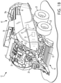
- baler 12 may be towed across a field by agricultural machine 10.
- Baler 12 may include housing 14, which may generally shield various internal components of baler 12.
- connection 10a such as a PTO
- pick-up assembly 16 may gather the material and move it up and into housing 14 for processing.
- bale 18 may be formed and may be ejected from the rear of baler 12.
- An antenna 15 is located on a cab 17 and is configured to receive and to transmit wireless signals to and from an externally located source of data information, such as is available over the web through a cloud system, or to and from a global positioning system (GPS) which is configured to supply location information machine control information to the controller 34.
- GPS global positioning system
- the GPS system directs the machine 10 through the field along a predetermined route to provide for planting, harvesting, plowing, and fertilizing. Other machine functions are contemplated.
- baler 12 may include one or more computing devices, such as controller 34.
- controller 34 may be a hardware, software, or hardware and software computing device, and may be configured to execute various computational and control functionality with respect to baler 12 (or machine 10).
- controller 34 may be in electronic or other communication with various components and devices of baler 12 (or tractor 10).
- controller 34 within baler 12 may be in electronic communication with various actuators, sensors, and other devices within (or outside of) baler 12.
- Controller 34 may communicate with various other components (including other controllers) in various known ways, including wirelessly.
- Pick-up assembly 16 includes rotary tine pick-up 22 for gathering crop material from a windrow (not shown). Material gathered by rotary tine pick-up 22 is routed to feeder 24, which further directs the material toward baling chamber 38 for compaction into a bale.
- a sound sensor (for example an audio sensor) 35 is located within the baler 12 and is configured to convert sound waves generated by the baler 12 into sound signals which are transmitted from the sound sensor 35 to the controller 34. Other locations of the sound sensor 35 are contemplated and are positioned in proximity to one or more components or parts that generate sound during operation of the baler 12.
- One or more sound sensors are contemplated and are located internally to or at the exterior of the baler 12. In additional embodiments, one or more sound sensors are located on the tractor 10. In different embodiments, the sound sensor includes a microphone, an accelerometer, or other vibration sensing device attached to or located near the harvesting machine or to the work implement, a hand held sensor near the machine, or a mobile sensor whose location can be changed as required.
- Baling chamber 38 which is depicted with upper panel 38a in place, may be a chamber of generally rectangular cross section extending axially along baler 12 in a generally front-to-back direction. Chamber 38 may be configured in various ways to receive material gathered by pick-up assembly 16, hold the material for compaction, then release the resulting bale from the back (or other portion) of baler 12 (e.g., as depicted for bale 18, in FIG. 1A ).
- Baling chamber 38 may be bounded on one or more sides (e.g., to the right and left, from the perspective of the forward direction of baler 12) by tension panels 40, which may be movable in order to control various aspects of a baling operation.
- tension panels 40 which may be movable in order to control various aspects of a baling operation.
- various actuators may be mounted to baler 12 and one or more of tension panels 40 such that the actuators may cause tension panels 40 to vary the cross-sectional area of baling chamber 38.
- hydraulic pistons may be configured to pivot tension panels 40 into (or out of) baling chamber 38, in order to decrease (or increase) the cross-sectional area of chamber 38 and thereby increase (or decrease) the force required to push a given amount of compacted crop material through chamber 38 (e.g., the pressure required for plunger 54 to move the bale through chamber 38).
- tension panels 40 may be utilized to vary the density of the resulting bale 18.
- Compaction of crop material within baling chamber 38 may be driven in various ways.
- a plunger (not shown in FIG. 1 B) may be driven by a crank arm assembly.
- power take off (“PTO") connection shaft 26 may be configured to receive rotational power from PTO shaft of machine 10 (e.g., via connection 10a, as shown in FIG. 1A ).
- PTO connection shaft 26 may be receiving rotational power from machine 10.
- various other configurations are also possible, such as configurations in which shaft 26 (or various other components of baler 12) may be selectively disengaged even if the PTO output of machine 10 is engaged.
- PTO connection shaft 26 provides rotational power to gear box 28.
- this power is routed through gear box 28 to crank arms 30, which are connected to plunger 54 via connecting rod(s) 32.
- Connecting rods 32 have been partially removed in FIG. 1B , for clarity of presentation.
- rotational power may be provided from machine 10 to crank arms 30.
- gear box 28 is powered by an electrical or hydraulic machine rather than by direct mechanical power from a PTO interface.
- rotation of PTO connection shaft 26 (e.g., as powered by the PTO output of machine 10) additionally (or alternatively) provides rotational power to various components of baler 12.
- the motion of various components of pick-up assembly 16, various tying mechanisms (not shown), pumps for hydraulic actuation of tension panels 38 (not shown), and so on, are driven via power connections of various known types (e.g., chain or belt drives) to PTO connection shaft 26 or associated components.
- a twine tying arrangement (not shown) is provided for wrapping and tying multiple loops of twine about a completed bale.
- the bale tying cycle in one embodiment, is initiated by a bale length sensor arrangement (not shown) including a toothed metering wheel (not shown) mounted on a shaft (not shown) extending horizontally across and being rotatably mounted to the top of the baling chamber 38.
- the metering wheel includes a toothed periphery which extends into the baling chamber 38 and is contacted by a forming bale so as to be rotated as the bale grows in length.
- the rotation of the metering wheel is sensed and converted into a signal representing bale length, with a control signal being sent to initiate the tying cycle when the forming bale reaches a length corresponding to a desired bale length.
- a twine tensioner or knotter system is described in U.S. Patent No. 8,617,834 to Deere & Company , the disclosure of which is hereby incorporated by reference.
- FIGS. 1A and 1B While a large square baler is described in FIGS. 1A and 1B , the present disclosure is not limited to large square balers, but includes round balers such as those found in US Patent Nos. 6,622,468 , 6,640,699 , 7,694,504 , the disclosures of which are incorporated by reference herein.
- the round baler does not include a compression chamber as does the large square baler.
- the present disclosure in not limited to a baler of a particular type, and is applicable to balers of different types including those having a precompression chamber, no precompression chamber, secondary rotors, or those having crop moving directly into a formation chamber.
- the present disclosure is also not limited to balers, but can also include other harvesting machines or crop processing machines such as chopping systems used on combines.
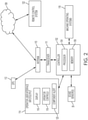
- FIG. 2 illustrates a schematic block diagram of a control system 100 configured to determine a component or systems malfunction of the work machine 12 using one or more sound sensors 35.
- the control system 100 includes one or more electronic controllers 102, also known as an electronic control unit (ECU), each of which is connected to a controller area network (CAN) bus (not shown) and to the various devices and components of the machine 100.
- the CAN bus is configured to transmit electric signals for the control of various devices connected to the bus as well as to transmit status signals that identify the status of the connected devices.
- the controller 102 includes a computer, computer system, or other programmable devices.
- the controller 102 includes one or more processors 104 (e.g. microprocessors), and an associated memory 106, which can be internal to the processor or external to the processor.
- the memory 106 includes, in different embodiments, random access memory (RAM) devices comprising the memory storage of the controller 102, as well as any other types of memory, e.g., cache memories, non-volatile or backup memories, programmable memories, or flash memories, and read-only memories.
- RAM random access memory
- the memory can include a memory storage physically located elsewhere from the processing devices, and can include any cache memory in a processing device, as well as any storage capacity used as a virtual memory, e.g., as stored on a mass storage device or another computer coupled to controller 102.
- the mass storage device can include a cache or other dataspace which can include databases.
- Memory storage in other embodiments, is located in a cloud system 108, also known as the "cloud", where the memory is located in the cloud at a distant location from the machine to provide the stored information wirelessly to the controller 102 through an antenna 110 operatively connected to a transceiver 111, which is operatively connected to the controller 102.
- the processor 104, and the memory 106 other types of controllers, processors, and memory are contemplated.
- the controller 102 executes or otherwise relies upon computer software applications, components, programs, objects, modules, or data structures, etc.
- Software routines resident in the included memory 106 of the controller 102, or other memory, are executed in response to the signals received from sensors, such as sound sensors 35, as well as signals received from other controllers such as an engine controller and a transmission controller.
- the controller 102 in other embodiments, also relies on one or more computer software applications, that are located in the "cloud” 108, where the cloud generally refers to a network storing data and/or computer software programs accessed through the internet.
- the executed software includes one or more specific applications, components, programs, objects, modules or sequences of instructions typically referred to as "program code".
- the program code includes one or more instructions located in memory and other storage devices which execute the instructions which are resident in memory, which are responsive to other instructions generated by the system, or which are provided at a user interface operated by the user.
- the machine 12 includes a plurality of sensors, in addition to the sound sensors 35, each of which in different embodiments, identifies machine device status and transmits sensor information to the controller 102.
- a GPS system 112 is wirelessly connected to the antenna 110 and either transmits electrical signals to the controller 102 or receives electrical signals from the controller 102 transmitted by the transceiver 111 using the antenna 110.
- a steering control signal can be provided by the global GPS system 112.
- An operator user interface 114 is operatively connected to the controller 102 and is located in the cab 17 to display machine information to an operator, located in the cab, as well as to enable the operator to control operations of the tractor 10, the baler 12, or other work machines.
- the user interface 114 includes a display 116 to display status information directed to the condition or status of the machine 10 as well as the baler 12. Status information includes, but is not limited to, the operating status of a machine operating system 118 including various components, parts, or systems of the baler 12.
- the user interface 114 further includes operator controls 119 configured to enable the operator to control the various functions and features of the machine operating system 118.
- a component alert device 120 is located at the user interface 114 and provide an alert function to an operator for alerting the operator in the event of a part or component being found be subject to malfunction.
- FIG. 2 illustrates one embodiment of a control system for the tractor 10 and baler 12 wherein the described features are located on either the tractor 10 or the baler 12.
- the sound sensors 35 are located on the baler 35 while the user interface 114 is located in the cab 17 of the tractor.
- all of the described features are located in the self-propelled combine.
- the machine operating systems 118 in different embodiments, are located on a single machine or on multiple machines as is the case for the tractor 10 and baler 12 of FIG. 1 .
- the machine operating systems are not limited to agricultural planters, harvesters, or balers, but also include to graders, mowers, grapplers, fellers, and plows. Other machine operating systems are contemplated.
- a remote control system 122 is used to remotely control operation of the machine 10 or baler 12 through web-based communication tools and platforms with the cloud 108, as is understood by those skilled in the art.
- an operator or manager is located at the remote control system 122, which due to its cloud communication protocol, is located remotely from the machine 10 and the baler 12.
- the control system 100 is a distributed control system having components locate at one or more of the work machines, the cloud, and the remote control system.
- control system 100 is configured to identify when a component or system of the machine being monitored has been damaged, through wear or through breakage.
- One or more of the sound sensors 35 are configured to receive sound generated by the machine and to transmit the received sound to the controller 102. Upon receipt at the controller 102, the sound is analyzed to determine if the received sound includes sound waves that are not typical of a properly operating work machine.
- the operation of the work machine is altered, such as by stopping the machine, and the controller 102 generates a status signal that is transmitted to the remote control system or to the user interface 114 to indicate that a part or component requires an inspection to determine if damage has occurred.
- the system Upon receipt of the status signal, the system generates an alert signal to a remote manager located at the remote control system or the user interface that the component may need to be replaced or repaired.
- the controller 102 continuously transmits a signal of the received sound waves to the remote control system or to the controller 102. Once received, the system determines if the received signal indicates a damaged component or system. If a possibility of damage exists, the system alerts the remote manager or operator of the potential damage. Additionally, upon receipt of the received signal, in one embodiment or more embodiments, the remote computing system or controller 102, after determining content of the received data, transmits a signal to stop operation of the machine. In a remotely operated machine, in one embodiment, the machine is directed to a location for maintenance or repair.
- a sound analysis is made of the transmitted sound signal to determine a frequency content of the sound in order to identify a feature of the sound signal that indicates a possibility of damage.
- the sound sensor receives sound waves from the entire machine, in one embodiment, and transmits the received sound waves to the controller. In other embodiments, multiple sensors are located at different locations to target a specific part, component, or system.
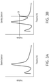
- a spectrum of frequencies is received at the controller 102 and from the spectrum of frequencies, frequencies of interest are identified and compared to a baseline frequency or frequencies to determine the presence of an anomaly, i.e.
- the baseline spectrum of frequencies provides a frequency spectrum of operating characteristics of the machine, its components, and systems.
- a baseline spectrum of frequencies is illustrated to show a range of frequencies for sound being sensed for an exemplary machine.
- the baseline spectrum of frequencies is identified when a machine is new and operating according to a design intent of the vehicle.
- the vehicle is selected as one that is operating according to the design intent and includes a spectrum of frequencies that identify a properly operating work machine.
- the baseline spectrum of frequencies is determined based on a single work machine and this baseline spectrum of frequencies is used as the baseline for all other work machines.
- each work machine is identified by its own spectrum of frequencies and a universal spectrum of frequencies based on a single work machine is not used. In either situation, a baseline frequency is identified as a baseline frequency profile to distinguish this profile from an operating spectrum profile described below.
- the sound spectrum changes, as shown in FIG. 3B .
- a particular frequency of sound has changed and includes a larger amplitude than the same frequency in FIG. 3A .
- an operating spectrum of frequencies is identified and compared to the baseline spectrum of frequencies to provide a comparison frequency profile. For instance in one embodiment, the baseline spectrum of frequencies is subtracted from the operating spectrum of frequencies to arrive at the change between frequency profiles.
- the controller 102 or control system, makes the comparison, identifies the change in amplitude, and sets an alert to indicate that the machine needs to be inspected to determine the source of the anomaly.
- an unacceptable change to a component could result in a change in frequency of the sensed sound.
- an operating frequency of a part can change over time and this change in frequency indicates that the part is damaged.
- a change in amplitude and a change in frequency indicates damage to a part.
- the frequencies are identified over a range of operating speeds (i.e. at a range of power take off (PTO) speeds) when the machine is "new" and the new spectrum is identified as a baseline spectrum.
- the frequencies are identified at one or more operating speeds of the PTO, but not at the full range of operating speeds.
- baseline frequency spectrums are recorded when a machine is new and the machine is stationary.
- the baseline frequency spectrums are recorded while running the machine in a field and/or while it is harvesting crop, when new.
- multiple sensors are placed at different locations of the machine wherein each sensor records a spectrum of frequencies for a part, component, or subsystem of the machine.
- the controller 102 then continuously receives the frequency spectrums while the machine is storing, or comparing in real time, the operating amplitude of each frequency.
- the magnitude of the received operating frequencies are compared to the magnitude of the baseline frequencies. If the magnitude of one or more of the actual frequencies is different than the baseline magnitude, by more than a predetermined amount, the controller 102, in one embodiment, determines that the change in magnitude beyond the predetermined amount indicates a change to a part or system that may be unacceptable. Once the magnitude is determined to exceed the predetermined amount, the controller notifies a manager at the remote computing system that a component may have failed or has been damaged.
- the received operating frequencies are transmitted to the remote computing system 122 and then compared to the baseline frequencies that are either stored in the remote computing system or at the cloud system 108.
- the machine is shut down for an inspection either in the field or at another location to determine if the change is unacceptable and indicates a worn or damaged part.
- the vehicle in one embodiment, is directed to a maintenance location in the remotely controlled vehicle.
- each of the frequencies of interest is mapped to a particular component or subsystem. If the controller 102 or the remote control system 122 identifies a frequency that is different from a baseline frequency, it suggests what component or subsystem may be causing the outlier frequency to occur.
- each of the baseline frequencies of interest is identified as being associated with a particular component or subsystem and are stored in a lookup table in the memory 106, stored in a memory in the cloud 108, or stored in a memory at the remote control system 122.
- the controller 102 first makes a comparison between the stored baseline spectrum frequencies and the operating spectrum frequencies to determine if the difference exceeds the predetermined value and if exceeded, the controller 102 identifies the compromised component of subsystem based on the lookup table.
- a comparison profile is provided to indicate which of the frequencies exceeds the predetermined value. If exceeded, the alert is provided for review by the operator or the manager of the remote control system 122.
- the “baseline frequency spectrum” refers to a sound profile of the work machine that includes a sound profile when the work machine is newly manufactured.
- the baseline spectrum frequency also includes frequencies that can change, if an individual part is changed or replaced. For instance, if a muffler is identified as being defective, a replacement muffler replaces the old muffler, and a new baseline is identified to include the frequency spectrum of the replacement muffler. In this situation, the current noise level is compared to the new baseline frequency spectrum, as opposed to being compared to the baseline frequency spectrum of the work machine when new. Consequently, the baseline frequency spectrum can change over time, and is updated as the need arises, as a revised baseline spectrum, such as when an old part is replaced with a new part.
- operator controls 119 include a user selectable button or other device that when selected resets the baseline frequency spectrum to an updated frequency spectrum based on the current frequency spectrum that has caused the alert.
- the operator controls 119 includes a baseline adjustment feature which permits the operator to alter, to increase, or to update, the baseline value that has caused the alert.
- the operator controls 119 include a feature that enables the operator to change a threshold value, which if exceeded by the current baseline frequency spectrum, is used to provide an alert.
- identifying the baseline includes identifying an initial baseline when the machine is new, identifying a different or updated baseline when a part or component is repaired or replaced, or identifying an updated baseline, based on identification of an updated baseline by the operator.
- Other types of updates are contemplated.
- baler has been described with respect to using a frequency spectrum for the identification of worn or damaged components or systems
- other agricultural machines are contemplated, each of which performs one or more operations used in the agricultural industry for preparing land and the planting and cultivation of crops.
- Each of the agricultural machines performs one or more operations and includes a variety of parts, components, devices, and subsystems directed to the performance of one or more operations.
- sounds are generated by the machine which include identifiable sound characteristics, i.e. frequencies.
- a change in frequencies from a baseline spectrum to an operating spectrum is used to identify abnormal operations.
- agricultural machines are not limited to the baler as described herein, but include other agricultural machines that provide a variety of operations, including but not limited to: reaping, gathering, threshing, cleaning, hauling, stacking, piling, plowing, bagging, and wrapping.
- present disclosure is applicable to other types of work machines including include to graders, mowers, grapplers, fellers, and plows, each of which include part, components, and subsystems configured to perform a work operation or function.
- Alternate embodiments of the control system include the sound sensor being located at a variety of different locations.
- the sound sensor is mounted directly to the work machine.
- work machines include, but are not limited to a harvesting unit such as a baler towed behind a tractor, or a self-propelled work machine.
- a hand-held or mobile sound sensor includes the use of the sound sensing device held or operated by a technician, but not mounted directly on the work machine.
- the technician could use the sound sensing device as part of a regularly scheduled maintenance check to determine if a component, such as a bearing, has been damaged or has failed during use.
- the hand-held device includes a cell phone or mobile telephone having an application (app) configured to identify machine failure or malfunction.
- a dedicated hand-held device is also contemplated.
- the sound sensor is mounted on a tractor in which the sound sensor is directed toward the work machine. The tractor sensor “listens” to the work machine and determines if the "sound spectrum" of the work machine has changed sufficiently to indicate that the work machine requires maintenance or repair. In another embodiment, the sound sensor listens to the tractor, or both the tractor and the work machine.
Landscapes
- Life Sciences & Earth Sciences (AREA)
- General Physics & Mathematics (AREA)
- Engineering & Computer Science (AREA)
- Physics & Mathematics (AREA)
- Mechanical Engineering (AREA)
- Health & Medical Sciences (AREA)
- Chemical & Material Sciences (AREA)
- Analytical Chemistry (AREA)
- Biochemistry (AREA)
- General Health & Medical Sciences (AREA)
- Immunology (AREA)
- Pathology (AREA)
- Soil Sciences (AREA)
- Environmental Sciences (AREA)
- Signal Processing (AREA)
- Human Computer Interaction (AREA)
- Harvester Elements (AREA)
Applications Claiming Priority (1)
| Application Number | Priority Date | Filing Date | Title |
|---|---|---|---|
| US17/020,926 US11776329B2 (en) | 2020-09-15 | 2020-09-15 | Sound analysis to identify a damaged component in a work machine |
Publications (1)
| Publication Number | Publication Date |
|---|---|
| EP3970467A1 true EP3970467A1 (fr) | 2022-03-23 |
Family
ID=77543333
Family Applications (1)
| Application Number | Title | Priority Date | Filing Date |
|---|---|---|---|
| EP21193683.6A Pending EP3970467A1 (fr) | 2020-09-15 | 2021-08-30 | Analyse sonore pour identifier un composant endommagé dans une machine de travail |
Country Status (4)
| Country | Link |
|---|---|
| US (1) | US11776329B2 (fr) |
| EP (1) | EP3970467A1 (fr) |
| CN (1) | CN114264457A (fr) |
| BR (1) | BR102021014973A2 (fr) |
Cited By (2)
| Publication number | Priority date | Publication date | Assignee | Title |
|---|---|---|---|---|
| EP4268563A1 (fr) * | 2022-04-27 | 2023-11-01 | CLAAS Selbstfahrende Erntemaschinen GmbH | Procédé de détermination d'un état d'usure d'une machine de travail agricole autonome |
| EP4331344A1 (fr) * | 2022-08-24 | 2024-03-06 | CLAAS Selbstfahrende Erntemaschinen GmbH | Procédé de détermination d'un état d'usure d'une moissonneuse agricole automotrice |
Families Citing this family (3)
| Publication number | Priority date | Publication date | Assignee | Title |
|---|---|---|---|---|
| US20230007485A1 (en) * | 2021-06-30 | 2023-01-05 | At&T Mobility Ii Llc | Systems and methods for network anomalies management |
| US11926333B2 (en) * | 2021-12-28 | 2024-03-12 | Blue River Technology Inc. | Compensatory actions for automated farming machine failure |
| CN116453526B (zh) * | 2023-04-24 | 2024-03-08 | 中国长江三峡集团有限公司 | 基于声音识别的水轮发电机组多工况异常监测方法及装置 |
Citations (9)
| Publication number | Priority date | Publication date | Assignee | Title |
|---|---|---|---|---|
| EP1221280A1 (fr) * | 2001-01-08 | 2002-07-10 | Deere & Company | Dispositif de surveillance de la fonction d'une machine de travail |
| US6622468B2 (en) | 2000-12-18 | 2003-09-23 | Deere & Company | Baling chamber arrangement of a large round baler designed for quick bale discharge |
| US6640699B2 (en) | 2001-06-06 | 2003-11-04 | Deere & Co. | Round baler bale chamber having simplified discharge arrangement |
| EP1386534A1 (fr) * | 2002-07-30 | 2004-02-04 | Deere & Company | Procédé et méthode pour déterminer l'acuité des lames de hacheuses |
| US7694504B1 (en) | 2008-09-24 | 2010-04-13 | Deere & Company | Secondary feeder rotor behind undershot precutter |
| US8617834B2 (en) | 2007-12-21 | 2013-12-31 | Siemens Healthcare Diagnostics Products Gmbh | Thromboplastin reagent with long-term stability |
| WO2020023269A1 (fr) * | 2018-07-25 | 2020-01-30 | Cnh Industrial America Llc | Système de surveillance aérien pour équipement agricole |
| US20200226851A1 (en) * | 2019-01-11 | 2020-07-16 | Cnh Industrial America Llc | System and method for detecting worn or damaged components of an agricultural machine based on acoustic data |
| US20210127540A1 (en) * | 2019-11-06 | 2021-05-06 | Cnh Industrial Canada, Ltd. | System and method for managing material accumulation relative to ground engaging tools of an agricultural implement |
Family Cites Families (12)
| Publication number | Priority date | Publication date | Assignee | Title |
|---|---|---|---|---|
| DE19725028A1 (de) | 1997-06-13 | 1998-12-17 | Claas Selbstfahr Erntemasch | Sensor für Erntemaschinen |
| DE10100444A1 (de) | 2001-01-08 | 2002-07-18 | Dieter Frey | Vorrichtung um Schwingungen und die dazu gehörenden Geräusche technischer Einrichtungen zu erfassen und auszuwerten |
| DE102004006848A1 (de) | 2004-02-12 | 2005-09-01 | Deere & Company, Moline | Verfahren und Überwachungssystem zur Überwachung des Zustands von Arbeitsmaschinen |
| US10775271B2 (en) * | 2012-08-22 | 2020-09-15 | Ge Global Sourcing Llc | System for determining conicity of a wheel based on measured vibrations |
| US10055903B2 (en) * | 2016-06-09 | 2018-08-21 | GM Global Technology Operations LLC | Vehicle health check via noise and vibration level |
| US20180012197A1 (en) * | 2016-07-07 | 2018-01-11 | NextEv USA, Inc. | Battery exchange licensing program based on state of charge of battery pack |
| US10489994B2 (en) * | 2016-11-16 | 2019-11-26 | Ford Global Technologies, Llc | Vehicle sound activation |
| US10486675B2 (en) * | 2017-11-11 | 2019-11-26 | Brian Hearing | Vehicle brake monitoring through ultrasonic emissions |
| US11506570B2 (en) * | 2018-08-27 | 2022-11-22 | Hyundai Motor Company | Method for sensing damage of bearing of engine using vibration signal |
| US11076274B1 (en) * | 2019-01-28 | 2021-07-27 | United Services Automobile Association (Usaa) | Monitoring of data to predict driving events |
| CN110386530A (zh) * | 2019-07-16 | 2019-10-29 | 浙江大学 | 一种面向故障诊断和安全预警的电梯监测系统及方法 |
| KR20210070477A (ko) * | 2019-12-04 | 2021-06-15 | 현대자동차주식회사 | 차량 고장 판단 장치 및 방법 |
-
2020
- 2020-09-15 US US17/020,926 patent/US11776329B2/en active Active
-
2021
- 2021-07-29 BR BR102021014973-6A patent/BR102021014973A2/pt unknown
- 2021-08-27 CN CN202111000178.2A patent/CN114264457A/zh active Pending
- 2021-08-30 EP EP21193683.6A patent/EP3970467A1/fr active Pending
Patent Citations (9)
| Publication number | Priority date | Publication date | Assignee | Title |
|---|---|---|---|---|
| US6622468B2 (en) | 2000-12-18 | 2003-09-23 | Deere & Company | Baling chamber arrangement of a large round baler designed for quick bale discharge |
| EP1221280A1 (fr) * | 2001-01-08 | 2002-07-10 | Deere & Company | Dispositif de surveillance de la fonction d'une machine de travail |
| US6640699B2 (en) | 2001-06-06 | 2003-11-04 | Deere & Co. | Round baler bale chamber having simplified discharge arrangement |
| EP1386534A1 (fr) * | 2002-07-30 | 2004-02-04 | Deere & Company | Procédé et méthode pour déterminer l'acuité des lames de hacheuses |
| US8617834B2 (en) | 2007-12-21 | 2013-12-31 | Siemens Healthcare Diagnostics Products Gmbh | Thromboplastin reagent with long-term stability |
| US7694504B1 (en) | 2008-09-24 | 2010-04-13 | Deere & Company | Secondary feeder rotor behind undershot precutter |
| WO2020023269A1 (fr) * | 2018-07-25 | 2020-01-30 | Cnh Industrial America Llc | Système de surveillance aérien pour équipement agricole |
| US20200226851A1 (en) * | 2019-01-11 | 2020-07-16 | Cnh Industrial America Llc | System and method for detecting worn or damaged components of an agricultural machine based on acoustic data |
| US20210127540A1 (en) * | 2019-11-06 | 2021-05-06 | Cnh Industrial Canada, Ltd. | System and method for managing material accumulation relative to ground engaging tools of an agricultural implement |
Cited By (2)
| Publication number | Priority date | Publication date | Assignee | Title |
|---|---|---|---|---|
| EP4268563A1 (fr) * | 2022-04-27 | 2023-11-01 | CLAAS Selbstfahrende Erntemaschinen GmbH | Procédé de détermination d'un état d'usure d'une machine de travail agricole autonome |
| EP4331344A1 (fr) * | 2022-08-24 | 2024-03-06 | CLAAS Selbstfahrende Erntemaschinen GmbH | Procédé de détermination d'un état d'usure d'une moissonneuse agricole automotrice |
Also Published As
| Publication number | Publication date |
|---|---|
| CN114264457A (zh) | 2022-04-01 |
| US11776329B2 (en) | 2023-10-03 |
| BR102021014973A2 (pt) | 2022-03-22 |
| US20220084333A1 (en) | 2022-03-17 |
Similar Documents
| Publication | Publication Date | Title |
|---|---|---|
| US11776329B2 (en) | Sound analysis to identify a damaged component in a work machine | |
| RU2738485C1 (ru) | Способ и система уборки урожая | |
| EP3398420B1 (fr) | Procédé et dispositif de contrôle de la vitesse d'une presse à balles | |
| EP1196022B1 (fr) | Capteur de rendement de cultures fourrageres | |
| EP4042848B1 (fr) | Réseau de capteurs d'identification de fréquence radio (rfid) pour machine de travail | |
| EP4072263A1 (fr) | Procédés et systèmes d'imagerie pour la récolte | |
| EP2353364A1 (fr) | Appareil de ramassage de récolte | |
| EP4338573A1 (fr) | Système agricole pour détecter un matériau végétal | |
| EP4364549A1 (fr) | Génération de réglages opérationnels améliorés et commande de machine agricole selon des cartes de fmis générées | |
| EP3939412A1 (fr) | Système et procédé d'estimation ou de prédiction de l'état de vie des composants d'une ramasseuse-presse agricole | |
| US20210185934A1 (en) | Methods and systems for measuring throughput in agricultural equipment | |
| EP4029358A1 (fr) | Réseau de capteurs d'identification de fréquence radio (rfid) pour machine de travail | |
| US20240049639A1 (en) | Actively variable swath gate position | |
| EP4230022A1 (fr) | Système et procédé de surveillance de l'état fonctionnel d'un composant de génération de chaleur d'une machine de travail | |
| EP4367999A1 (fr) | Commande de machine agricole et génération de réglages opérationnels sur la base d'images agricoles liées géographiquement | |
| Rogovskii | ADAPTABILITY OF SELF-PROPELLED FORAGE HARVESTERS TO SMART TECHNOLOGIES | |
| US20230403980A1 (en) | Variable speed conditioner rolls for mower-conditioner | |
| US20220408632A1 (en) | Agricultural implement system with a controller that controls travel and power take off coupling in response to plug conditions | |
| CN115119607A (zh) | 确定农业收割机的农作物处理部段中的振动模式的方法 |
Legal Events
| Date | Code | Title | Description |
|---|---|---|---|
| PUAI | Public reference made under article 153(3) epc to a published international application that has entered the european phase |
Free format text: ORIGINAL CODE: 0009012 |
|
| STAA | Information on the status of an ep patent application or granted ep patent |
Free format text: STATUS: THE APPLICATION HAS BEEN PUBLISHED |
|
| AK | Designated contracting states |
Kind code of ref document: A1 Designated state(s): AL AT BE BG CH CY CZ DE DK EE ES FI FR GB GR HR HU IE IS IT LI LT LU LV MC MK MT NL NO PL PT RO RS SE SI SK SM TR |
|
| STAA | Information on the status of an ep patent application or granted ep patent |
Free format text: STATUS: REQUEST FOR EXAMINATION WAS MADE |
|
| 17P | Request for examination filed |
Effective date: 20220923 |
|
| RBV | Designated contracting states (corrected) |
Designated state(s): AL AT BE BG CH CY CZ DE DK EE ES FI FR GB GR HR HU IE IS IT LI LT LU LV MC MK MT NL NO PL PT RO RS SE SI SK SM TR |
|
| STAA | Information on the status of an ep patent application or granted ep patent |
Free format text: STATUS: EXAMINATION IS IN PROGRESS |
|
| 17Q | First examination report despatched |
Effective date: 20230718 |