EP3970439B1 - Konfiguration eines direktzugriffsverfahrens - Google Patents
Konfiguration eines direktzugriffsverfahrens Download PDFInfo
- Publication number
- EP3970439B1 EP3970439B1 EP20726024.1A EP20726024A EP3970439B1 EP 3970439 B1 EP3970439 B1 EP 3970439B1 EP 20726024 A EP20726024 A EP 20726024A EP 3970439 B1 EP3970439 B1 EP 3970439B1
- Authority
- EP
- European Patent Office
- Prior art keywords
- random access
- mac
- response message
- success response
- wireless device
- Prior art date
- Legal status (The legal status is an assumption and is not a legal conclusion. Google has not performed a legal analysis and makes no representation as to the accuracy of the status listed.)
- Active
Links
Images


Classifications
-
- H—ELECTRICITY
- H04—ELECTRIC COMMUNICATION TECHNIQUE
- H04W—WIRELESS COMMUNICATION NETWORKS
- H04W74/00—Wireless channel access
- H04W74/08—Non-scheduled access, e.g. ALOHA
- H04W74/0833—Random access procedures, e.g. with 4-step access
- H04W74/0841—Random access procedures, e.g. with 4-step access with collision treatment
- H04W74/085—Random access procedures, e.g. with 4-step access with collision treatment collision avoidance
-
- H—ELECTRICITY
- H04—ELECTRIC COMMUNICATION TECHNIQUE
- H04W—WIRELESS COMMUNICATION NETWORKS
- H04W74/00—Wireless channel access
- H04W74/08—Non-scheduled access, e.g. ALOHA
- H04W74/0833—Random access procedures, e.g. with 4-step access
-
- H—ELECTRICITY
- H04—ELECTRIC COMMUNICATION TECHNIQUE
- H04W—WIRELESS COMMUNICATION NETWORKS
- H04W76/00—Connection management
- H04W76/20—Manipulation of established connections
-
- H—ELECTRICITY
- H04—ELECTRIC COMMUNICATION TECHNIQUE
- H04W—WIRELESS COMMUNICATION NETWORKS
- H04W72/00—Local resource management
- H04W72/20—Control channels or signalling for resource management
- H04W72/21—Control channels or signalling for resource management in the uplink direction of a wireless link, i.e. towards the network
-
- H—ELECTRICITY
- H04—ELECTRIC COMMUNICATION TECHNIQUE
- H04W—WIRELESS COMMUNICATION NETWORKS
- H04W72/00—Local resource management
- H04W72/20—Control channels or signalling for resource management
- H04W72/23—Control channels or signalling for resource management in the downlink direction of a wireless link, i.e. towards a terminal
-
- H—ELECTRICITY
- H04—ELECTRIC COMMUNICATION TECHNIQUE
- H04W—WIRELESS COMMUNICATION NETWORKS
- H04W74/00—Wireless channel access
- H04W74/002—Transmission of channel access control information
- H04W74/006—Transmission of channel access control information in the downlink, i.e. towards the terminal
-
- H—ELECTRICITY
- H04—ELECTRIC COMMUNICATION TECHNIQUE
- H04W—WIRELESS COMMUNICATION NETWORKS
- H04W74/00—Wireless channel access
- H04W74/08—Non-scheduled access, e.g. ALOHA
- H04W74/0833—Random access procedures, e.g. with 4-step access
- H04W74/0836—Random access procedures, e.g. with 4-step access with 2-step access
-
- H—ELECTRICITY
- H04—ELECTRIC COMMUNICATION TECHNIQUE
- H04W—WIRELESS COMMUNICATION NETWORKS
- H04W76/00—Connection management
- H04W76/20—Manipulation of established connections
- H04W76/27—Transitions between radio resource control [RRC] states
-
- H—ELECTRICITY
- H04—ELECTRIC COMMUNICATION TECHNIQUE
- H04W—WIRELESS COMMUNICATION NETWORKS
- H04W80/00—Wireless network protocols or protocol adaptations to wireless operation
- H04W80/02—Data link layer protocols
Definitions
- the present application relates generally to a wireless communication network, and relates more particularly to configuration of a random access procedure in such a network.
- the single network response in the 2-step procedure includes all of the same information as the two network responses in the 4-step procedure (e.g., including the RRC signalling), the delay and latency improvements from the 2-step nature of the procedure are hampered.
- the remaining information e.g., the RRC signalling
- ZTE ET AL "Transmission of MAC SOU for SRB/DRB in 2-step RACH", 3GPP DRAFT; R2-1906307 CONSIDERATION ON THE TRANSMISSION OF MAC SOU FOR SRBDRB IN 2-STEP RACH, 3RD GENERATION PARTNERSHIP PROJECT (3GPP) discloses a solution for transmitting DL MAC SDU for SRB/DRB in 2-step RACH.
- US 2017/318606 A1 discloses a solution for transmitting a MAC PDU, containing an RRC message and a data volume and power headroom (DV-PH) report but no BSR, using a uplink grant received in a random access response.
- a MAC PDU containing an RRC message and a data volume and power headroom (DV-PH) report but no BSR, using a uplink grant received in a random access response.
- DV-PH data volume and power headroom
- EMAIL DISCUSSION RAPPORTEUR ZTE: "Procedures and mgsB content [105bis#30][NR/2-step RACH]", R2-1906308, 2019-05-13 , is a collection of thoughts from different companies on the topic of procedures and msgB content.
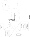
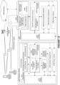
- FIG. 1 shows a wireless communication network 10 according to some embodiments.
- the wireless communication network 10 includes a radio access network (RAN) 10A (e.g., based on New Radio, NR) and a core network (CN) 10B.
- the RAN 10A includes a network node 12 (e.g., base station) that provides radio access to a wireless device 14.
- this radio access may be provided in unlicensed frequency spectrum.
- the unlicensed frequency spectrum is frequency spectrum within which transmissions may be performed without a license from a licensor (which may be a regulatory or governing entity, e.g., the United States Federal Communications Commission, FCC, or the International Telecommunication Union, ITU).
- a licensor which may be a regulatory or governing entity, e.g., the United States Federal Communications Commission, FCC, or the International Telecommunication Union, ITU.
- the RAN 10A via the radio access connects the wireless device 14 to the CN 10B, which may in turn connect to one or more data networks (e.g., the Internet).
- the wireless device 14 is configured to perform a random access procedure with the network node 12.
- the random access procedure may for instance be performed in order for the wireless device 14 to acquire uplink synchronization, to establish or resume a radio resource control (RRC) connection, etc.
- RRC radio resource control
- the random access procedure as shown includes two steps, e.g., as opposed to the conventional 4 steps.
- the wireless device 14 performs a transmission 16 on a random access channel (RACH) and an uplink shared channel (e.g., a physical uplink shared channel, PUSCH).
- This transmission 16 may be referred to as MSG A.
- the transmission 16 on the RACH may convey a random access preamble.
- the transmission 16 on the uplink shared channel may convey an RRC establishment request or RRC resume request.
- the transmission 16 on the RACH and the transmission 16 on the uplink shared channel may be performed in the same subframe, or in successive subframes, e.g., such that the transmission 16 on the uplink shared channel is performed before any response is received to the transmission 16 on the RACH.
- the network node 12 transmits a response to the RACH and uplink shared channel transmission 16. If the network node 12 successfully decoded the RACH and the uplink shared channel payload, the network node 12 transmits a random access success response message (also referred to as a random access success response, or simply, success response). This random access success response message correspondingly indicates that both the RACH and the uplink shared channel payload were decoded successfully. Note in this regard that, unlike the traditional 4-step procedure, the random access success response is transmitted as a response to both the RACH and the uplink shared channel transmission 16.
- a random access success response message also referred to as a random access success response, or simply, success response.
- the network node 12 in some embodiments conveys this random access success response message 18 within or as a transmission referred to as MSG B.
- the random access success response message 18 is included in a medium access control (MAC) protocol data unit (PDU) 20.
- MAC medium access control
- this MAC PDU 20 may be a shared message that it is addressed to multiple wireless devices, e.g., because it includes multiple random access success responses for respective ones of the wireless devices.
- the random access success response message 18 includes a contention resolution identity, a cell radio network temporary identity (C-RNTI), a timing advance (TA) command, an uplink grant, and/or a random access preamble identifier (RAPID).
- C-RNTI cell radio network temporary identity
- TA timing advance
- RAPID random access preamble identifier
- the MAC PDU 20 carrying the random access success response message 18 also includes a MAC service data unit (SDU) 22 for a signaling radio bearer (SRB) or a data radio bearer (DRB).
- SRB signaling radio bearer
- DRB data radio bearer
- the MAC SDU 22 for an SRB may convey for instance RRC signaling, e.g., in the form of one or more RRC messages such as an RRC setup message or an RRC resume message.
- the MAC SDU 22 for a DRB may convey user plane data, e.g., for an early data transmission.
- RRC signaling it is configurable as to whether or not the MAC PDU 20 carrying the random access success response message 18 includes RRC signaling.
- the information 24 further indicates one or more parameter values that govern reception of the random access success response message 18 (or the MAC PDU 20 carrying the message 18).
- the one or more parameter values may include a value for a reception window within which the wireless device 14 must receive the random access success response message 18 or the MAC PDU 20 carrying the random access success response message 18.
- the one or more parameter values may include an identity (e.g., Cell Radio Network Temporary Identity, C-RNTI, or Random Access RNTI, RA-RNTI) with which the wireless device 14 is to descramble a control channel on which, or a control channel search space within which, the random access success response message 18 or a MAC PDU 20 carrying the random access success response message 18 is to be sent.
- the information 24 may indicate a backoff procedure for random access by the wireless device 14.
- the wireless device 14 processes the received MAC PDU 20 based on the received information 24.
- one or more parameter values governing random access depend on or are otherwise based on whether a MAC SDU 22 for an SRB or DRB is included in the received MAC PDU 20.
- a random access response reception timer (corresponding to the reception window) has a value that depends or is based on whether the MAC SDU 22 for an SRB or DRB is to be received by the wireless device 14 in the same PAC PDU as a MAC PDU 20 carrying the random access success response message 18.
- the timer value (and reception window) may be relatively larger or smaller, for instance, depending respectively on whether or not the MAC SDU 22 for the SRB or DRB is to be received by the wireless device 14 in the same PAC PDU as a MAC PDU 20 carrying the random access success response message 18.
- the wireless device 14 may determine the value for the random access response reception timer (i.e., the reception window) based on the received information 24.
- a radio network temporary identity e.g., C-RNTI
- Configurability via the information 24 may advantageously enable the network node 12 to adapt inclusion of the MAC SDU 22 for SRB or DRB in the MAC PDU 20 carrying the success response 18, e.g., on an as-needed basis to account for varying circumstances or conditions, or to account for a specific network deployment (e.g., in unlicensed frequency spectrum).
- the network node 12 may determine whether or not the MAC SDU 22 for an SRB or DRB is to be included in the same MAC PDU as the MAC PDU 20 carrying the random access success response message 18 based on one or more of: a type of network deployment within which the network node 12 is deployed; expected radio resource control, RRC, processing delay; delay between a central unit and a distributed unit of the network node 12; cell layout; a category or type of the wireless device 14; whether the wireless device 14 is in connected mode, idle mode, or inactive mode; a random access trigger; a priority of the wireless device 14 or of a transmission for the wireless device 14; a random access load; and/or radio resource control, RRC, processing load.
- RRC radio resource control
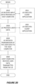
- Figure 2 depicts a method performed by a wireless device 14 in accordance with particular embodiments.
- the method includes receiving, from a network node 12, information 24 indicating whether or not a medium access control, MAC, service data unit, SDU, 22 for a signaling radio bearer, SRB, or data radio bearer, DRB, is to be received by the wireless device 14 in the same MAC protocol data unit, PDU, as a MAC PDU 20 carrying a random access success response message 18 (Block 200).
- the random access success response message 18 indicates both a random access channel and an uplink shared channel payload were decoded successfully.
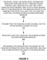
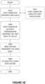
- Figure 3 depicts a method performed by a network node 12 in accordance with other particular embodiments.
- the method includes transmitting, from the network node 12 to a wireless device 14, information 24 indicating whether or not a medium access control, MAC, service data unit, SDU, 22 for a signaling radio bearer, SRB, or data radio bearer, DRB, is to be received by the wireless device 14 in the same MAC protocol data unit, PDU, as a MAC PDU 20 carrying a random access success response message 18 (Block 300).
- the random access success response message 18 indicates both a random access channel and an uplink shared channel payload were decoded successfully.
- the method may further include receiving the random access channel and the uplink shared channel payload, e.g., as conveyed by msgA described herein (Block 310).
- the method may alternatively or additionally include transmitting a MAC PDU 20 carrying the random access success response message 18 (Block 320).
- the processing circuitry may be configured to execute program code stored in memory, which may include one or several types of memory such as read-only memory (ROM), random-access memory, cache memory, flash memory devices, optical storage devices, etc.
- Program code stored in memory may include program instructions for executing one or more telecommunications and/or data communications protocols as well as instructions for carrying out one or more of the techniques described herein, in several embodiments.
- the memory stores program code that, when executed by the one or more processors, carries out the techniques described herein.
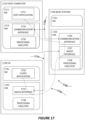
- FIG. 4 for example illustrates a wireless device 400 (e.g., wireless device 14) as implemented in accordance with one or more embodiments.
- the wireless device 400 includes processing circuitry 410 and communication circuitry 420.
- the communication circuitry 420 e.g., radio circuitry
- the processing circuitry 410 is configured to perform processing described above, e.g., in Figure 2 , such as by executing instructions stored in memory 430.
- the processing circuitry 410 in this regard may implement certain functional means, units, or modules.
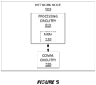
- FIG. 5 illustrates a network node 500 (e.g., network node 12) as implemented in accordance with one or more embodiments.
- the network node 500 includes processing circuitry 510 and communication circuitry 520.
- the communication circuitry 520 is configured to transmit and/or receive information to and/or from one or more other nodes, e.g., via any communication technology.
- the processing circuitry 510 is configured to perform processing described above, e.g., in Figure 3 , such as by executing instructions stored in memory 530.
- the processing circuitry 510 in this regard may implement certain functional means, units, or modules.
- a computer program comprises instructions which, when executed on at least one processor of an apparatus, cause the apparatus to carry out any of the respective processing described above.
- a computer program in this regard may comprise one or more code modules corresponding to the means or units described above.
- Embodiments further include a carrier containing such a computer program.
- This carrier may comprise one of an electronic signal, optical signal, radio signal, or computer readable storage medium.
- embodiments herein also include a computer program product stored on a non-transitory computer readable (storage or recording) medium and comprising instructions that, when executed by a processor of an apparatus, cause the apparatus to perform as described above.
- Embodiments further include a computer program product comprising program code portions for performing the steps of any of the embodiments herein when the computer program product is executed by a computing device.
- This computer program product may be stored on a computer readable recording medium.
- the wireless device 14 may be exemplified as a UE
- the network node 12 may be exemplified as an eNB or gNB
- the MAC SDU 22 for an SRB or DRB may be exemplified as conveying an RRC message
- the random access success response message 18 may be exemplified as a successRAR message.
- Option 1 corresponds to the MAC PDU 20 not including a MAC SDU 22 for an SRB or DRB
- Option 2 corresponds to the MAC PDU 20 including a MAC SDU 22 for an SRB or DRB.
- Figure 6 shows a legacy 4-step Random Access (RA) that is the baseline for both Long Term Evolution (LTE) and New Radio (NR).
- RA Random Access
- UE user equipment
- the user equipment (UE) in this 4-step procedure randomly selects a preamble to transmit.
- the UE then starts the ra-ResponseWindow in which the RA Response (RAR) message must be received.
- RAR RA Response
- the maximum duration of the the ra-ResponseWindow is 10 ms (20 ms is discussed for NR Unlicensed, NR-U).
- the eNB When the eNB detects the preamble, it estimates the Timing alignment (TA) the UE should use in order to obtain uplink (UL) synchronization at the eNB. The eNB responds with the TA and a grant for Msg3 in the RAR message.
- TA Timing alignment
- UL uplink
- the UE transmits its identifier for contention resolution (part of RRC message or C-RNTI). Upon transmission of Msg3, the UE starts the ra-Contention Resolution Timer in which Msg4 must be received.
- the maximum configurable duration is 64 sub frames (64ms).
- this timer is longer than the ra-ResponseWindow is that it may involve RRC processing and needs to account for centralized unit (CU) / distributed unit (DU) delays, where a CU and DU may be different parts of the eNB that implement different layers of a protocol stack, e.g., the CU may terminate higher layer and/or less time-critical protocols, such as the Packet Data Convergence Protocol (PDCP) and Radio Resource Control (RRC) protocols, whereas the DU by contrast may terminate lower layer and/or more time-critical protocols, such as the Radio Link Control (RLC), Medium Access Control (MAC), and physical layer protocols.
- PDCP Packet Data Convergence Protocol
- RRC Radio Resource Control
- a MAC subheader with Backoff Indicator consists of five header fields E/T/R/R/BI as described in Figure 8 (corresponding to Figure 6 .1.5-1 of 3GPP TS 38.321 v15.4.0).
- a MAC subPDU with Backoff Indicator (BI) only is placed at the beginning of the MAC PDU, if included.
- 'MAC subPDU(s) with RAPID only' and 'MAC subPDU(s) with RAPID and MAC RAR' can be placed anywhere between MAC subPDU with Backoff Indicator only (if any) and padding (if any).
- a MAC subheader with RAPID consists of three header fields E/T/RAPID as described in Figure 9 (corresponding to Figure 6 .1.5-2 of TS 38.321 v15.4.0).
- a UE If a UE receives a RAR with the E/T/R/R/BI mac subheader but no 'MAC subPDU(s) with RAPID and MAC RAR' with RAPID matching its preamble transmission, the UE will back-off for a random time between 0 and a time indicated by the BI field before doing a new preamble transmission attempt, i.e. return to Random Access Resource selection (Section 5.1.2 in 38.321 v15.4.0).
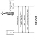
- a 2-step RA procedure gives much shorter latency than the ordinary 4 step RA.
- the preamble (transmitted on PRACH) and a message corresponding to Message 3 (transmitted on PUSCH) in the 4 step RA are transmitted in the same or in two subsequent sub frames.
- the first message in the 2-step procedure is denoted Message A (MsgA).
- the 2-step procedure is depicted in Figure 10 .
- the grant is linked to a particular preamble.
- the same kind of mapping will be needed in the 2-step procedure.
- the PUSCH resource may be time multiplexed, frequency multiplexed or code multiplexed.
- MsgA i.e. both the preamble and Msg 3
- the eNB Upon successful reception of MsgA (i.e. both the preamble and Msg 3), the eNB will respond with a TA (which by assumption should not be needed or just give very minor updates) and a Msg 4 for contention resolution.
- TA which by assumption should not be needed or just give very minor updates
- Msg 4 for contention resolution.
- the second message in the 2-step procedure is denoted Message B (MsgB) in NR-U.
- msgB reception timer In the two step procedure, there will be a timer, hereafter called “msgB reception timer", in which msgB must be received. It should be noted that in the 4-step procedure, there were two different timers governing when the network response must be received. In the 2-step procedure, only one is used.
- MsgA may contain the UEs C-RNTI and the msgB may be identified by Physical Downlink Control Channel (PDCCH) scrambled by the C-RNTI and a TA and possibly an uplink (UL) grant.
- PDCCH Physical Downlink Control Channel
- msgA may contain common control channel (CCCH) (RRC message) and the msgB may include a contention resolution MAC Control Element (CE), TA, C-RNTI and most possibly an RRC message.
- CCCH common control channel
- CE contention resolution MAC Control Element
- One option (referred to as Option 1) is to have a "SuccessRAR" containing contention resolution MAC CE, TA, C-RNTI and possibly a RAPID.
- the SuccessRaAR is addressed to a single UE (not multiplexed), possibly using the RA-RNTI.
- the contention resolution is complete and the gNB can send the RRC message part in a later stage.
- the advantage with this approach is that contention resolution can be carried out quickly, e.g. using a msgB reception timer with a setting corresponding to the ra-ResponseWindow in the 4-step procedure. This is illustrated in Figure 11 .
- this may mean extra latency to account for RRC processing and CU/DU delays implying the need for a longer setting of msgB reception timer (corresponding to the ra-ContentionResolutionTimer in the 4-step procedure).
- Option 2 Another option (referred to as Option 2) would be to not send a SuccessRAR and instead wait until a complete msgB can be sent.
- This has the advantage that only 2 LBTs (Listen Before Talk) are needed in case of NR-U (NR Unlicensed), compared to three LBTs if the RRC part is sent in a later stage.
- the overall latency would be similar (since the UE needs to wait until it receives the RRC part in case of the first option) between the options, except in case the SuccessRAR would fail LBT, in which case the second option would be better.
- This option is illustrated in Figure 12 .
- the setting of msgB reception timer depends on which of the two options (msgB sent in two steps or in one step) is used. Both options have advantages and may be preferable in different situations. However they may be difficult to use simultaneously.
- the second option could require a longer length of msgB reception window compared to the first option using SuccessRAR.
- the two options could also require different RNTIs to identify msgB (e.g. first option might use RA-RNTI but the second option would need a new RNTI capable of handling longer reception windows).
- the methods to do back off could be different under the different options, since if a back off is sent in the shorter window, it might back off a user which otherwise would receive its msgB after the shorter window has expired.
- Certain embodiments may provide one or more of the following technical advantage(s). Some embodiments enable a network to order the UE to follow a procedure consisting of a SuccessRAR and a later RRC message or a procedure where only one msgB containing both content from the SuccessRAR and the RRC message is included.
- Option 1 is referred to as the case where msgB in the 2-step Random Access procedure is sent in two steps: (i) A first step for contention resolution, C-RNTI assignment, and possibly TA command; and (ii) a second step consisting of an RRC message, e.g., as shown in Figure 11 .
- Option 2 is referred to as the case where msgB in the 2-step Random Access procedure is sent in one step (message/MAC PDU), e.g., as shown in Figure 12 .
- the msgB in this option 2 may contain contention resolution, C-RNTI assignment, possibly TA command and RRC message.
- the network configures in system information (SI) which option (Option 1 or Option 2) is used.
- SI system information
- the configuration can be included in either the RACH-ConfigCommon or RACH-ConfigGeneric Information Element (IE) in System Information (SI) Block Type 1 (SIB1).
- IE System Information
- SIB1 System Information Block Type 1
- the SI in some embodiments may contain a flag to indicate which option is configured and to indicate parameter values of the msgB reception window. The UE will then, based on the configuration in the SI, know which procedure to follow and which parameter values to use.
- Option 1 or Option 2 may also consist of a mix of the two options, where option 1 is used for UEs in connected mode and option 2 is used for UEs in idle or inactive mode.
- the option to use (Option 1 or Option 2) is signaled through dedicated RRC signaling.
- An RRC message in this case may contain a flag to indicate which option is configured and to indicate parameter values of msgB reception window. The UE will then, based on the configuration in the RRC message, know which procedure to follow and which parameter values to use. This may be used in e.g. hand over.
- the network may decide on which option to use based on network deployment including expected RRC delays, CU/DU fronthaul or backhaul delay and/or cell layout.
- the network may decide on which option to use based on UE categories and/or random access trigger. For example, UEs doing random access for high priority use cases may use one option while other UEs use the other option. This could be specified in the 3GPP standard and possibly combined with configuration in SI.
- a wireless network such as the example wireless network illustrated in Figure 13 .
- the wireless network of Figure 13 only depicts network 1306, network nodes 1360 and 1360b, and WDs 1310, 1310b, and 1310c.
- a wireless network may further include any additional elements suitable to support communication between wireless devices or between a wireless device and another communication device, such as a landline telephone, a service provider, or any other network node or end device.
- network node 1360 and wireless device (WD) 1310 are depicted with additional detail.
- the wireless network may provide communication and other types of services to one or more wireless devices to facilitate the wireless devices' access to and/or use of the services provided by, or via, the wireless network.
- the wireless network may comprise and/or interface with any type of communication, telecommunication, data, cellular, and/or radio network or other similar type of system.
- the wireless network may be configured to operate according to specific standards or other types of predefined rules or procedures.
- particular embodiments of the wireless network may implement communication standards, such as Global System for Mobile Communications (GSM), Universal Mobile Telecommunications System (UMTS), Long Term Evolution (LTE), Narrowband Internet of Things (NB-IoT), and/or other suitable 2G, 3G, 4G, or 5G standards; wireless local area network (WLAN) standards, such as the IEEE 802.11 standards; and/or any other appropriate wireless communication standard, such as the Worldwide Interoperability for Microwave Access (WiMax), Bluetooth, Z-Wave and/or ZigBee standards.
- GSM Global System for Mobile Communications
- UMTS Universal Mobile Telecommunications System
- LTE Long Term Evolution
- NB-IoT Narrowband Internet of Things
- WLAN wireless local area network
- WiMax Worldwide Interoper
- Network 1306 may comprise one or more backhaul networks, core networks, IP networks, public switched telephone networks (PSTNs), packet data networks, optical networks, wide-area networks (WANs), local area networks (LANs), wireless local area networks (WLANs), wired networks, wireless networks, metropolitan area networks, and other networks to enable communication between devices.
- PSTNs public switched telephone networks
- WANs wide-area networks
- LANs local area networks
- WLANs wireless local area networks
- wired networks wireless networks, metropolitan area networks, and other networks to enable communication between devices.
- Network node 1360 and WD 1310 comprise various components described in more detail below. These components work together in order to provide network node and/or wireless device functionality, such as providing wireless connections in a wireless network.
- the wireless network may comprise any number of wired or wireless networks, network nodes, base stations, controllers, wireless devices, relay stations, and/or any other components or systems that may facilitate or participate in the communication of data and/or signals whether via wired or wireless connections.
- network node refers to equipment capable, configured, arranged and/or operable to communicate directly or indirectly with a wireless device and/or with other network nodes or equipment in the wireless network to enable and/or provide wireless access to the wireless device and/or to perform other functions (e.g., administration) in the wireless network.
- network nodes include, but are not limited to, access points (APs) (e.g., radio access points), base stations (BSs) (e.g., radio base stations, Node Bs, evolved Node Bs (eNBs) and NR NodeBs (gNBs)).
- APs access points
- BSs base stations
- eNBs evolved Node Bs
- gNBs NR NodeBs
- Base stations may be categorized based on the amount of coverage they provide (or, stated differently, their transmit power level) and may then also be referred to as femto base stations, pico base stations, micro base stations, or macro base stations.
- a base station may be a relay node or a relay donor node controlling a relay.
- a network node may also include one or more (or all) parts of a distributed radio base station such as centralized digital units and/or remote radio units (RRUs), sometimes referred to as Remote Radio Heads (RRHs). Such remote radio units may or may not be integrated with an antenna as an antenna integrated radio.
- RRUs remote radio units
- RRHs Remote Radio Heads
- Such remote radio units may or may not be integrated with an antenna as an antenna integrated radio.
- Parts of a distributed radio base station may also be referred to as nodes in a distributed antenna system (DAS).
- DAS distributed antenna system
- network nodes include multi-standard radio (MSR) equipment such as MSR BSs, network controllers such as radio network controllers (RNCs) or base station controllers (BSCs), base transceiver stations (BTSs), transmission points, transmission nodes, multi-cell/multicast coordination entities (MCEs), core network nodes (e.g., MSCs, MMEs), O&M nodes, OSS nodes, SON nodes, positioning nodes (e.g., E-SMLCs), and/or MDTs.
- MSR multi-standard radio
- RNCs radio network controllers
- BSCs base station controllers
- BTSs base transceiver stations
- transmission points transmission nodes
- MCEs multi-cell/multicast coordination entities
- core network nodes e.g., MSCs, MMEs
- O&M nodes e.g., OSS nodes, SON nodes, positioning nodes (e.g., E-SMLCs), and/or MDTs.
- network node 1360 may be composed of multiple physically separate components (e.g., a NodeB component and a RNC component, or a BTS component and a BSC component, etc.), which may each have their own respective components.
- network node 1360 comprises multiple separate components (e.g., BTS and BSC components)
- one or more of the separate components may be shared among several network nodes.
- a single RNC may control multiple NodeB's.
- each unique NodeB and RNC pair may in some instances be considered a single separate network node.
- network node 1360 may be configured to support multiple radio access technologies (RATs).
- RATs radio access technologies
- Processing circuitry 1370 is configured to perform any determining, calculating, or similar operations (e.g., certain obtaining operations) described herein as being provided by a network node. These operations performed by processing circuitry 1370 may include processing information obtained by processing circuitry 1370 by, for example, converting the obtained information into other information, comparing the obtained information or converted information to information stored in the network node, and/or performing one or more operations based on the obtained information or converted information, and as a result of said processing making a determination.
- processing information obtained by processing circuitry 1370 by, for example, converting the obtained information into other information, comparing the obtained information or converted information to information stored in the network node, and/or performing one or more operations based on the obtained information or converted information, and as a result of said processing making a determination.
- Processing circuitry 1370 may comprise a combination of one or more of a microprocessor, controller, microcontroller, central processing unit, digital signal processor, application-specific integrated circuit, field programmable gate array, or any other suitable computing device, resource, or combination of hardware, software and/or encoded logic operable to provide, either alone or in conjunction with other network node 1360 components, such as device readable medium 1380, network node 1360 functionality.
- processing circuitry 1370 may execute instructions stored in device readable medium 1380 or in memory within processing circuitry 1370. Such functionality may include providing any of the various wireless features, functions, or benefits discussed herein.
- processing circuitry 1370 may include a system on a chip (SOC).
- SOC system on a chip
- Device readable medium 1380 may comprise any form of volatile or non-volatile computer readable memory including, without limitation, persistent storage, solid-state memory, remotely mounted memory, magnetic media, optical media, random access memory (RAM), read-only memory (ROM), mass storage media (for example, a hard disk), removable storage media (for example, a flash drive, a Compact Disk (CD) or a Digital Video Disk (DVD)), and/or any other volatile or non-volatile, non-transitory device readable and/or computer-executable memory devices that store information, data, and/or instructions that may be used by processing circuitry 1370.
- volatile or non-volatile computer readable memory including, without limitation, persistent storage, solid-state memory, remotely mounted memory, magnetic media, optical media, random access memory (RAM), read-only memory (ROM), mass storage media (for example, a hard disk), removable storage media (for example, a flash drive, a Compact Disk (CD) or a Digital Video Disk (DVD)), and/or any other volatile or
- Device readable medium 1380 may store any suitable instructions, data or information, including a computer program, software, an application including one or more of logic, rules, code, tables, etc. and/or other instructions capable of being executed by processing circuitry 1370 and, utilized by network node 1360.
- Device readable medium 1380 may be used to store any calculations made by processing circuitry 1370 and/or any data received via interface 1390.
- processing circuitry 1370 and device readable medium 1380 may be considered to be integrated.
- Interface 1390 is used in the wired or wireless communication of signalling and/or data between network node 1360, network 1306, and/or WDs 1310. As illustrated, interface 1390 comprises port(s)/terminal(s) 1394 to send and receive data, for example to and from network 1306 over a wired connection. Interface 1390 also includes radio front end circuitry 1392 that may be coupled to, or in certain embodiments a part of, antenna 1362. Radio front end circuitry 1392 comprises filters 1398 and amplifiers 1396. Radio front end circuitry 1392 may be connected to antenna 1362 and processing circuitry 1370. Radio front end circuitry may be configured to condition signals communicated between antenna 1362 and processing circuitry 1370.
- Radio front end circuitry 1392 may receive digital data that is to be sent out to other network nodes or WDs via a wireless connection. Radio front end circuitry 1392 may convert the digital data into a radio signal having the appropriate channel and bandwidth parameters using a combination of filters 1398 and/or amplifiers 1396. The radio signal may then be transmitted via antenna 1362. Similarly, when receiving data, antenna 1362 may collect radio signals which are then converted into digital data by radio front end circuitry 1392. The digital data may be passed to processing circuitry 1370. In other embodiments, the interface may comprise different components and/or different combinations of components.
- network node 1360 may not include separate radio front end circuitry 1392, instead, processing circuitry 1370 may comprise radio front end circuitry and may be connected to antenna 1362 without separate radio front end circuitry 1392.
- processing circuitry 1370 may comprise radio front end circuitry and may be connected to antenna 1362 without separate radio front end circuitry 1392.
- all or some of RF transceiver circuitry 1372 may be considered a part of interface 1390.
- interface 1390 may include one or more ports or terminals 1394, radio front end circuitry 1392, and RF transceiver circuitry 1372, as part of a radio unit (not shown), and interface 1390 may communicate with baseband processing circuitry 1374, which is part of a digital unit (not shown).
- Antenna 1362 may include one or more antennas, or antenna arrays, configured to send and/or receive wireless signals. Antenna 1362 may be coupled to radio front end circuitry 1390 and may be any type of antenna capable of transmitting and receiving data and/or signals wirelessly. In some embodiments, antenna 1362 may comprise one or more omni-directional, sector or panel antennas operable to transmit/receive radio signals between, for example, 2 GHz and 66 GHz. An omni-directional antenna may be used to transmit/receive radio signals in any direction, a sector antenna may be used to transmit/receive radio signals from devices within a particular area, and a panel antenna may be a line of sight antenna used to transmit/receive radio signals in a relatively straight line. In some instances, the use of more than one antenna may be referred to as MIMO. In certain embodiments, antenna 1362 may be separate from network node 1360 and may be connectable to network node 1360 through an interface or port.
- Antenna 1362, interface 1390, and/or processing circuitry 1370 may be configured to perform any receiving operations and/or certain obtaining operations described herein as being performed by a network node. Any information, data and/or signals may be received from a wireless device, another network node and/or any other network equipment. Similarly, antenna 1362, interface 1390, and/or processing circuitry 1370 may be configured to perform any transmitting operations described herein as being performed by a network node. Any information, data and/or signals may be transmitted to a wireless device, another network node and/or any other network equipment.
- Power circuitry 1387 may comprise, or be coupled to, power management circuitry and is configured to supply the components of network node 1360 with power for performing the functionality described herein. Power circuitry 1387 may receive power from power source 1386. Power source 1386 and/or power circuitry 1387 may be configured to provide power to the various components of network node 1360 in a form suitable for the respective components (e.g., at a voltage and current level needed for each respective component). Power source 1386 may either be included in, or external to, power circuitry 1387 and/or network node 1360.
- network node 1360 may be connectable to an external power source (e.g., an electricity outlet) via an input circuitry or interface such as an electrical cable, whereby the external power source supplies power to power circuitry 1387.
- power source 1386 may comprise a source of power in the form of a battery or battery pack which is connected to, or integrated in, power circuitry 1387. The battery may provide backup power should the external power source fail.
- Other types of power sources such as photovoltaic devices, may also be used.
- network node 1360 may include additional components beyond those shown in Figure 13 that may be responsible for providing certain aspects of the network node's functionality, including any of the functionality described herein and/or any functionality necessary to support the subject matter described herein.
- network node 1360 may include user interface equipment to allow input of information into network node 1360 and to allow output of information from network node 1360. This may allow a user to perform diagnostic, maintenance, repair, and other administrative functions for network node 1360.
- wireless device refers to a device capable, configured, arranged and/or operable to communicate wirelessly with network nodes and/or other wireless devices.
- the term WD may be used interchangeably herein with user equipment (UE).
- Communicating wirelessly may involve transmitting and/or receiving wireless signals using electromagnetic waves, radio waves, infrared waves, and/or other types of signals suitable for conveying information through air.
- a WD may be configured to transmit and/or receive information without direct human interaction.
- a WD may be designed to transmit information to a network on a predetermined schedule, when triggered by an internal or external event, or in response to requests from the network.
- Examples of a WD include, but are not limited to, a smart phone, a mobile phone, a cell phone, a voice over IP (VoIP) phone, a wireless local loop phone, a desktop computer, a personal digital assistant (PDA), a wireless cameras, a gaming console or device, a music storage device, a playback appliance, a wearable terminal device, a wireless endpoint, a mobile station, a tablet, a laptop, a laptop-embedded equipment (LEE), a laptop-mounted equipment (LME), a smart device, a wireless customer-premise equipment (CPE). a vehicle-mounted wireless terminal device, etc.
- a WD may support device-to-device (D2D) communication, for example by implementing a 3GPP standard for sidelink communication, vehicle-to-vehicle (V2V), vehicle-to-infrastructure (V2I), vehicle-to-everything (V2X) and may in this case be referred to as a D2D communication device.
- D2D device-to-device
- V2V vehicle-to-vehicle
- V2I vehicle-to-infrastructure
- V2X vehicle-to-everything
- a WD may represent a machine or other device that performs monitoring and/or measurements, and transmits the results of such monitoring and/or measurements to another WD and/or a network node.
- the WD may in this case be a machine-to-machine (M2M) device, which may in a 3GPP context be referred to as an MTC device.
- M2M machine-to-machine
- the WD may be a UE implementing the 3GPP narrow band internet of things (NB-loT) standard.
- NB-loT narrow band internet of things
- machines or devices are sensors, metering devices such as power meters, industrial machinery, or home or personal appliances (e.g. refrigerators, televisions, etc.) personal wearables (e.g., watches, fitness trackers, etc.).
- a WD may represent a vehicle or other equipment that is capable of monitoring and/or reporting on its operational status or other functions associated with its operation.
- a WD as described above may represent the endpoint of a wireless connection, in which case the device may be referred to as a wireless terminal. Furthermore, a WD as described above may be mobile, in which case it may also be referred to as a mobile device or a mobile terminal.
- wireless device 1310 includes antenna 1311, interface 1314, processing circuitry 1320, device readable medium 1330, user interface equipment 1332, auxiliary equipment 1334, power source 1336 and power circuitry 1337.
- WD 1310 may include multiple sets of one or more of the illustrated components for different wireless technologies supported by WD 1310, such as, for example, GSM, WCDMA, LTE, NR, WiFi, WiMAX, NB-IoT, or Bluetooth wireless technologies, just to mention a few. These wireless technologies may be integrated into the same or different chips or set of chips as other components within WD 1310.
- Antenna 1311 may include one or more antennas or antenna arrays, configured to send and/or receive wireless signals, and is connected to interface 1314. In certain alternative embodiments, antenna 1311 may be separate from WD 1310 and be connectable to WD 1310 through an interface or port. Antenna 1311, interface 1314, and/or processing circuitry 1320 may be configured to perform any receiving or transmitting operations described herein as being performed by a WD. Any information, data and/or signals may be received from a network node and/or another WD. In some embodiments, radio front end circuitry and/or antenna 1311 may be considered an interface.
- interface 1314 comprises radio front end circuitry 1312 and antenna 1311.
- Radio front end circuitry 1312 comprise one or more filters 1318 and amplifiers 1316.
- Radio front end circuitry 1314 is connected to antenna 1311 and processing circuitry 1320, and is configured to condition signals communicated between antenna 1311 and processing circuitry 1320.
- Radio front end circuitry 1312 may be coupled to or a part of antenna 1311.
- WD 1310 may not include separate radio front end circuitry 1312; rather, processing circuitry 1320 may comprise radio front end circuitry and may be connected to antenna 1311.
- some or all of RF transceiver circuitry 1322 may be considered a part of interface 1314.
- Radio front end circuitry 1312 may receive digital data that is to be sent out to other network nodes or WDs via a wireless connection. Radio front end circuitry 1312 may convert the digital data into a radio signal having the appropriate channel and bandwidth parameters using a combination of filters 1318 and/or amplifiers 1316. The radio signal may then be transmitted via antenna 1311. Similarly, when receiving data, antenna 1311 may collect radio signals which are then converted into digital data by radio front end circuitry 1312. The digital data may be passed to processing circuitry 1320. In other embodiments, the interface may comprise different components and/or different combinations of components.
- Processing circuitry 1320 may comprise a combination of one or more of a microprocessor, controller, microcontroller, central processing unit, digital signal processor, application-specific integrated circuit, field programmable gate array, or any other suitable computing device, resource, or combination of hardware, software, and/or encoded logic operable to provide, either alone or in conjunction with other WD 1310 components, such as device readable medium 1330, WD 1310 functionality. Such functionality may include providing any of the various wireless features or benefits discussed herein.
- processing circuitry 1320 may execute instructions stored in device readable medium 1330 or in memory within processing circuitry 1320 to provide the functionality disclosed herein.
- processing circuitry 1320 includes one or more of RF transceiver circuitry 1322, baseband processing circuitry 1324, and application processing circuitry 1326.
- the processing circuitry may comprise different components and/or different combinations of components.
- processing circuitry 1320 of WD 1310 may comprise a SOC.
- RF transceiver circuitry 1322, baseband processing circuitry 1324, and application processing circuitry 1326 may be on separate chips or sets of chips.
- part or all of baseband processing circuitry 1324 and application processing circuitry 1326 may be combined into one chip or set of chips, and RF transceiver circuitry 1322 may be on a separate chip or set of chips.
- part or all of RF transceiver circuitry 1322 and baseband processing circuitry 1324 may be on the same chip or set of chips, and application processing circuitry 1326 may be on a separate chip or set of chips.
- part or all of RF transceiver circuitry 1322, baseband processing circuitry 1324, and application processing circuitry 1326 may be combined in the same chip or set of chips.
- RF transceiver circuitry 1322 may be a part of interface 1314.
- RF transceiver circuitry 1322 may condition RF signals for processing circuitry 1320.
- processing circuitry 1320 executing instructions stored on device readable medium 1330, which in certain embodiments may be a computerreadable storage medium.
- some or all of the functionality may be provided by processing circuitry 1320 without executing instructions stored on a separate or discrete device readable storage medium, such as in a hard-wired manner.
- processing circuitry 1320 can be configured to perform the described functionality. The benefits provided by such functionality are not limited to processing circuitry 1320 alone or to other components of WD 1310, but are enjoyed by WD 1310 as a whole, and/or by end users and the wireless network generally.
- Processing circuitry 1320 may be configured to perform any determining, calculating, or similar operations (e.g., certain obtaining operations) described herein as being performed by a WD. These operations, as performed by processing circuitry 1320, may include processing information obtained by processing circuitry 1320 by, for example, converting the obtained information into other information, comparing the obtained information or converted information to information stored by WD 1310, and/or performing one or more operations based on the obtained information or converted information, and as a result of said processing making a determination.
- processing information obtained by processing circuitry 1320 by, for example, converting the obtained information into other information, comparing the obtained information or converted information to information stored by WD 1310, and/or performing one or more operations based on the obtained information or converted information, and as a result of said processing making a determination.
- Device readable medium 1330 may be operable to store a computer program, software, an application including one or more of logic, rules, code, tables, etc. and/or other instructions capable of being executed by processing circuitry 1320.
- Device readable medium 1330 may include computer memory (e.g., Random Access Memory (RAM) or Read Only Memory (ROM)), mass storage media (e.g., a hard disk), removable storage media (e.g., a Compact Disk (CD) or a Digital Video Disk (DVD)), and/or any other volatile or non-volatile, non-transitory device readable and/or computer executable memory devices that store information, data, and/or instructions that may be used by processing circuitry 1320.
- processing circuitry 1320 and device readable medium 1330 may be considered to be integrated.
- User interface equipment 1332 may provide components that allow for a human user to interact with WD 1310. Such interaction may be of many forms, such as visual, audial, tactile, etc. User interface equipment 1332 may be operable to produce output to the user and to allow the user to provide input to WD 1310. The type of interaction may vary depending on the type of user interface equipment 1332 installed in WD 1310. For example, if WD 1310 is a smart phone, the interaction may be via a touch screen; if WD 1310 is a smart meter, the interaction may be through a screen that provides usage (e.g., the number of gallons used) or a speaker that provides an audible alert (e.g., if smoke is detected).
- usage e.g., the number of gallons used
- a speaker that provides an audible alert
- User interface equipment 1332 may include input interfaces, devices and circuits, and output interfaces, devices and circuits. User interface equipment 1332 is configured to allow input of information into WD 1310, and is connected to processing circuitry 1320 to allow processing circuitry 1320 to process the input information. User interface equipment 1332 may include, for example, a microphone, a proximity or other sensor, keys/buttons, a touch display, one or more cameras, a USB port, or other input circuitry. User interface equipment 1332 is also configured to allow output of information from WD 1310, and to allow processing circuitry 1320 to output information from WD 1310. User interface equipment 1332 may include, for example, a speaker, a display, vibrating circuitry, a USB port, a headphone interface, or other output circuitry. Using one or more input and output interfaces, devices, and circuits, of user interface equipment 1332, WD 1310 may communicate with end users and/or the wireless network, and allow them to benefit from the functionality described herein.
- Auxiliary equipment 1334 is operable to provide more specific functionality which may not be generally performed by WDs. This may comprise specialized sensors for doing measurements for various purposes, interfaces for additional types of communication such as wired communications etc. The inclusion and type of components of auxiliary equipment 1334 may vary depending on the embodiment and/or scenario.
- Power circuitry 1337 may also in certain embodiments be operable to deliver power from an external power source to power source 1336. This may be, for example, for the charging of power source 1336. Power circuitry 1337 may perform any formatting, converting, or other modification to the power from power source 1336 to make the power suitable for the respective components of WD 1310 to which power is supplied.
- Figure 14 illustrates one embodiment of a UE in accordance with various aspects described herein.
- a user equipment or UE may not necessarily have a user in the sense of a human user who owns and/or operates the relevant device.
- a UE may represent a device that is intended for sale to, or operation by, a human user but which may not, or which may not initially, be associated with a specific human user (e.g., a smart sprinkler controller).
- a UE may represent a device that is not intended for sale to, or operation by, an end user but which may be associated with or operated for the benefit of a user (e.g., a smart power meter).
- UE 14200 may be any UE identified by the 3 rd Generation Partnership Project (3GPP), including a NB-loT UE, a machine type communication (MTC) UE, and/or an enhanced MTC (eMTC) UE.
- UE 1400 as illustrated in Figure 14 , is one example of a WD configured for communication in accordance with one or more communication standards promulgated by the 3 rd Generation Partnership Project (3GPP), such as 3GPP's GSM, UMTS, LTE, and/or 5G standards.
- 3GPP 3 rd Generation Partnership Project
- GSM Global System for Mobile communications
- UMTS Universal Mobile communications
- LTE Long Term Evolution
- 5G 5G
- the term WD and UE may be used interchangeable. Accordingly, although Figure 14 is a UE, the components discussed herein are equally applicable to a WD, and vice-versa.
- UE 1400 includes processing circuitry 1401 that is operatively coupled to input/output interface 1405, radio frequency (RF) interface 1409, network connection interface 1411, memory 1415 including random access memory (RAM) 1417, read-only memory (ROM) 1419, and storage medium 1421 or the like, communication subsystem 1431, power source 1433, and/or any other component, or any combination thereof.
- Storage medium 1421 includes operating system 1423, application program 1425, and data 1427. In other embodiments, storage medium 1421 may include other similar types of information.
- Certain UEs may utilize all of the components shown in Figure 14 , or only a subset of the components. The level of integration between the components may vary from one UE to another UE. Further, certain UEs may contain multiple instances of a component, such as multiple processors, memories, transceivers, transmitters, receivers, etc.
- processing circuitry 1401 may be configured to process computer instructions and data.
- Processing circuitry 1401 may be configured to implement any sequential state machine operative to execute machine instructions stored as machine-readable computer programs in the memory, such as one or more hardware-implemented state machines (e.g., in discrete logic, FPGA, ASIC, etc.); programmable logic together with appropriate firmware; one or more stored program, general-purpose processors, such as a microprocessor or Digital Signal Processor (DSP), together with appropriate software; or any combination of the above.
- the processing circuitry 1401 may include two central processing units (CPUs). Data may be information in a form suitable for use by a computer.
- input/output interface 1405 may be configured to provide a communication interface to an input device, output device, or input and output device.
- UE 1400 may be configured to use an output device via input/output interface 1405.
- An output device may use the same type of interface port as an input device.
- a USB port may be used to provide input to and output from UE 1400.
- the output device may be a speaker, a sound card, a video card, a display, a monitor, a printer, an actuator, an emitter, a smartcard, another output device, or any combination thereof.
- UE 1400 may be configured to use an input device via input/output interface 1405 to allow a user to capture information into UE 1400.
- RF interface 1409 may be configured to provide a communication interface to RF components such as a transmitter, a receiver, and an antenna.
- Network connection interface 1411 may be configured to provide a communication interface to network 1443a.
- Network 1443a may encompass wired and/or wireless networks such as a local-area network (LAN), a wide-area network (WAN), a computer network, a wireless network, a telecommunications network, another like network or any combination thereof.
- network 1443a may comprise a Wi-Fi network.
- Network connection interface 1411 may be configured to include a receiver and a transmitter interface used to communicate with one or more other devices over a communication network according to one or more communication protocols, such as Ethernet, TCP/IP, SONET, ATM, or the like.
- Network connection interface 1411 may implement receiver and transmitter functionality appropriate to the communication network links (e.g., optical, electrical, and the like). The transmitter and receiver functions may share circuit components, software or firmware, or alternatively may be implemented separately.
- RAM 1417 may be configured to interface via bus 1402 to processing circuitry 1401 to provide storage or caching of data or computer instructions during the execution of software programs such as the operating system, application programs, and device drivers.
- ROM 1419 may be configured to provide computer instructions or data to processing circuitry 1401.
- ROM 1419 may be configured to store invariant low-level system code or data for basic system functions such as basic input and output (I/O), startup, or reception of keystrokes from a keyboard that are stored in a non-volatile memory.
- Storage medium 1421 may be configured to include memory such as RAM, ROM, programmable read-only memory (PROM), erasable programmable read-only memory (EPROM), electrically erasable programmable read-only memory (EEPROM), magnetic disks, optical disks, floppy disks, hard disks, removable cartridges, or flash drives.
- storage medium 1421 may be configured to include operating system 1423, application program 1425 such as a web browser application, a widget or gadget engine or another application, and data file 1427.
- Storage medium 1421 may store, for use by UE 1400, any of a variety of various operating systems or combinations of operating systems.
- Storage medium 1421 may be configured to include a number of physical drive units, such as redundant array of independent disks (RAID), floppy disk drive, flash memory, USB flash drive, external hard disk drive, thumb drive, pen drive, key drive, high-density digital versatile disc (HD-DVD) optical disc drive, internal hard disk drive, Blu-Ray optical disc drive, holographic digital data storage (HDDS) optical disc drive, external mini-dual in-line memory module (DIMM), synchronous dynamic random access memory (SDRAM), external micro-DIMM SDRAM, smartcard memory such as a subscriber identity module or a removable user identity (SIM/RUIM) module, other memory, or any combination thereof.
- RAID redundant array of independent disks
- HD-DVD high-density digital versatile disc
- HDDS holographic digital data storage
- DIMM external mini-dual in-line memory module
- SDRAM synchronous dynamic random access memory
- SDRAM synchronous dynamic random access memory
- smartcard memory such as a subscriber identity module or a removable user
- processing circuitry 1401 may be configured to communicate with network 1443b using communication subsystem 1431.
- Network 1443a and network 1443b may be the same network or networks or different network or networks.
- Communication subsystem 1431 may be configured to include one or more transceivers used to communicate with network 1443b.
- communication subsystem 1431 may be configured to include one or more transceivers used to communicate with one or more remote transceivers of another device capable of wireless communication such as another WD, UE, or base station of a radio access network (RAN) according to one or more communication protocols, such as IEEE 802.14, CDMA, WCDMA, GSM, LTE, UTRAN, WiMax, or the like.
- RAN radio access network
- Each transceiver may include transmitter 1433 and/or receiver 1435 to implement transmitter or receiver functionality, respectively, appropriate to the RAN links (e.g., frequency allocations and the like). Further, transmitter 1433 and receiver 1435 of each transceiver may share circuit components, software or firmware, or alternatively may be implemented separately.
- communication subsystem 1431 may be configured to include any of the components described herein.
- processing circuitry 1401 may be configured to communicate with any of such components over bus 1402.
- any of such components may be represented by program instructions stored in memory that when executed by processing circuitry 1401 perform the corresponding functions described herein.
- the functionality of any of such components may be partitioned between processing circuitry 1401 and communication subsystem 1431.
- the non-computationally intensive functions of any of such components may be implemented in software or firmware and the computationally intensive functions may be implemented in hardware.
- FIG. 15 is a schematic block diagram illustrating a virtualization environment 1500 in which functions implemented by some embodiments may be virtualized.
- virtualizing means creating virtual versions of apparatuses or devices which may include virtualizing hardware platforms, storage devices and networking resources.
- virtualization can be applied to a node (e.g., a virtualized base station or a virtualized radio access node) or to a device (e.g., a UE, a wireless device or any other type of communication device) or components thereof and relates to an implementation in which at least a portion of the functionality is implemented as one or more virtual components (e.g., via one or more applications, components, functions, virtual machines or containers executing on one or more physical processing nodes in one or more networks).
- a node e.g., a virtualized base station or a virtualized radio access node
- a device e.g., a UE, a wireless device or any other type of communication device
- some or all of the functions described herein may be implemented as virtual components executed by one or more virtual machines implemented in one or more virtual environments 1500 hosted by one or more of hardware nodes 1530. Further, in embodiments in which the virtual node is not a radio access node or does not require radio connectivity (e.g., a core network node), then the network node may be entirely virtualized.
- the virtual node is not a radio access node or does not require radio connectivity (e.g., a core network node)
- the network node may be entirely virtualized.
- the functions may be implemented by one or more applications 1520 (which may alternatively be called software instances, virtual appliances, network functions, virtual nodes, virtual network functions, etc.) operative to implement some of the features, functions, and/or benefits of some of the embodiments disclosed herein.
- Applications 1520 are run in virtualization environment 1500 which provides hardware 1530 comprising processing circuitry 1560 and memory 1590.
- Memory 1590 contains instructions 1595 executable by processing circuitry 1560 whereby application 1520 is operative to provide one or more of the features, benefits, and/or functions disclosed herein.
- Virtualization environment 1500 comprises general-purpose or special-purpose network hardware devices 1530 comprising a set of one or more processors or processing circuitry 1560, which may be commercial off-the-shelf (COTS) processors, dedicated Application Specific Integrated Circuits (ASICs), or any other type of processing circuitry including digital or analog hardware components or special purpose processors.
- processors or processing circuitry 1560 which may be commercial off-the-shelf (COTS) processors, dedicated Application Specific Integrated Circuits (ASICs), or any other type of processing circuitry including digital or analog hardware components or special purpose processors.
- Each hardware device may comprise memory 1590-1 which may be non-persistent memory for temporarily storing instructions 1595 or software executed by processing circuitry 1560.
- Each hardware device may comprise one or more network interface controllers (NICs) 1570, also known as network interface cards, which include physical network interface 1580.
- NICs network interface controllers
- Each hardware device may also include non-transitory, persistent, machine-readable storage media 1590-2 having stored therein software 1595 and/or instructions executable by processing circuitry 1560.
- Software 1595 may include any type of software including software for instantiating one or more virtualization layers 1550 (also referred to as hypervisors), software to execute virtual machines 1540 as well as software allowing it to execute functions, features and/or benefits described in relation with some embodiments described herein.
- Virtual machines 1540 comprise virtual processing, virtual memory, virtual networking or interface and virtual storage, and may be run by a corresponding virtualization layer 1550 or hypervisor. Different embodiments of the instance of virtual appliance 1520 may be implemented on one or more of virtual machines 1540, and the implementations may be made in different ways.
- processing circuitry 1560 executes software 1595 to instantiate the hypervisor or virtualization layer 1550, which may sometimes be referred to as a virtual machine monitor (VMM).
- Virtualization layer 1550 may present a virtual operating platform that appears like networking hardware to virtual machine 1540.
- NFV network function virtualization
- NFV may be used to consolidate many network equipment types onto industry standard high volume server hardware, physical switches, and physical storage, which can be located in data centers, and customer premise equipment.
- virtual machine 1540 may be a software implementation of a physical machine that runs programs as if they were executing on a physical, non-virtualized machine.
- Each of virtual machines 1540, and that part of hardware 1530 that executes that virtual machine be it hardware dedicated to that virtual machine and/or hardware shared by that virtual machine with others of the virtual machines 1540, forms a separate virtual network elements (VNE).
- VNE virtual network elements
- one or more radio units 15200 that each include one or more transmitters 15220 and one or more receivers 15210 may be coupled to one or more antennas 15225.
- Radio units 15200 may communicate directly with hardware nodes 1530 via one or more appropriate network interfaces and may be used in combination with the virtual components to provide a virtual node with radio capabilities, such as a radio access node or a base station.
- a communication system includes telecommunication network 1610, such as a 3GPP-type cellular network, which comprises access network 1611, such as a radio access network, and core network 1614.
- Access network 1611 comprises a plurality of base stations 1612a, 1612b, 1612c, such as NBs, eNBs, gNBs or other types of wireless access points, each defining a corresponding coverage area 1613a, 1613b, 1613c.
- Each base station 1612a, 1612b, 1612c is connectable to core network 1614 over a wired or wireless connection 1615.
- a first UE 1691 located in coverage area 1613c is configured to wirelessly connect to, or be paged by, the corresponding base station 1612c.
- a second UE 1692 in coverage area 1613a is wirelessly connectable to the corresponding base station 1612a. While a plurality of UEs 1691, 1692 are illustrated in this example, the disclosed embodiments are equally applicable to a situation where a sole UE is in the coverage area or where a sole UE is connecting to the corresponding base station 1612.
- Telecommunication network 1610 is itself connected to host computer 1630, which may be embodied in the hardware and/or software of a standalone server, a cloudimplemented server, a distributed server or as processing resources in a server farm.
- Host computer 1630 may be under the ownership or control of a service provider, or may be operated by the service provider or on behalf of the service provider.
- Connections 1621 and 1622 between telecommunication network 1610 and host computer 1630 may extend directly from core network 1614 to host computer 1630 or may go via an optional intermediate network 1620.
- Intermediate network 1620 may be one of, or a combination of more than one of, a public, private or hosted network; intermediate network 1620, if any, may be a backbone network or the Internet; in particular, intermediate network 1620 may comprise two or more sub-networks (not shown).
- the communication system of Figure 16 as a whole enables connectivity between the connected UEs 1691, 1692 and host computer 1630.
- the connectivity may be described as an over-the-top (OTT) connection 1650.
- Host computer 1630 and the connected UEs 1691, 1692 are configured to communicate data and/or signaling via OTT connection 1650, using access network 1611, core network 1614, any intermediate network 1620 and possible further infrastructure (not shown) as intermediaries.
- OTT connection 1650 may be transparent in the sense that the participating communication devices through which OTT connection 1650 passes are unaware of routing of uplink and downlink communications.
- base station 1612 may not or need not be informed about the past routing of an incoming downlink communication with data originating from host computer 1630 to be forwarded (e.g., handed over) to a connected UE 1691. Similarly, base station 1612 need not be aware of the future routing of an outgoing uplink communication originating from the UE 1691 towards the host computer 1630.
- FIG. 17 illustrates host computer communicating via a base station with a user equipment over a partially wireless connection in accordance with some embodiments
- host computer 1710 comprises hardware 1715 including communication interface 1716 configured to set up and maintain a wired or wireless connection with an interface of a different communication device of communication system 1700.
- Host computer 1710 further comprises processing circuitry 1718, which may have storage and/or processing capabilities.
- processing circuitry 1718 may comprise one or more programmable processors, application-specific integrated circuits, field programmable gate arrays or combinations of these (not shown) adapted to execute instructions.
- Host computer 1710 further comprises software 1711, which is stored in or accessible by host computer 1710 and executable by processing circuitry 1718.
- Software 1711 includes host application 1712.
- Host application 1712 may be operable to provide a service to a remote user, such as UE 1730 connecting via OTT connection 1750 terminating at UE 1730 and host computer 1710. In providing the service to the remote user, host application 1712 may provide user data which is transmitted using OTT connection 1750.
- Communication system 1700 further includes base station 1720 provided in a telecommunication system and comprising hardware 1725 enabling it to communicate with host computer 1710 and with UE 1730.
- Hardware 1725 may include communication interface 1726 for setting up and maintaining a wired or wireless connection with an interface of a different communication device of communication system 1700, as well as radio interface 1727 for setting up and maintaining at least wireless connection 1770 with UE 1730 located in a coverage area (not shown in Figure 17 ) served by base station 1720.
- Communication interface 1726 may be configured to facilitate connection 1760 to host computer 1710. Connection 1760 may be direct or it may pass through a core network (not shown in Figure 17 ) of the telecommunication system and/or through one or more intermediate networks outside the telecommunication system.
- hardware 1725 of base station 1720 further includes processing circuitry 1728, which may comprise one or more programmable processors, application-specific integrated circuits, field programmable gate arrays or combinations of these (not shown) adapted to execute instructions.
- Base station 1720 further has software 1721 stored internally or accessible via an external connection.
- Communication system 1700 further includes UE 1730 already referred to. Its hardware 1735 may include radio interface 1737 configured to set up and maintain wireless connection 1770 with a base station serving a coverage area in which UE 1730 is currently located. Hardware 1735 of UE 1730 further includes processing circuitry 1738, which may comprise one or more programmable processors, application-specific integrated circuits, field programmable gate arrays or combinations of these (not shown) adapted to execute instructions. UE 1730 further comprises software 1731, which is stored in or accessible by UE 1730 and executable by processing circuitry 1738. Software 1731 includes client application 1732. Client application 1732 may be operable to provide a service to a human or non-human user via UE 1730, with the support of host computer 1710.
- an executing host application 1712 may communicate with the executing client application 1732 via OTT connection 1750 terminating at UE 1730 and host computer 1710.
- client application 1732 may receive request data from host application 1712 and provide user data in response to the request data.
- OTT connection 1750 may transfer both the request data and the user data.
- Client application 1732 may interact with the user to generate the user data that it provides.
- host computer 1710, base station 1720 and UE 1730 illustrated in Figure 17 may be similar or identical to host computer 1630, one of base stations 1612a, 1612b, 1612c and one of UEs 1691, 1692 of Figure 16 , respectively.
- the inner workings of these entities may be as shown in Figure 17 and independently, the surrounding network topology may be that of Figure 16 .
- OTT connection 1750 has been drawn abstractly to illustrate the communication between host computer 1710 and UE 1730 via base station 1720, without explicit reference to any intermediary devices and the precise routing of messages via these devices.
- Network infrastructure may determine the routing, which it may be configured to hide from UE 1730 or from the service provider operating host computer 1710, or both. While OTT connection 1750 is active, the network infrastructure may further take decisions by which it dynamically changes the routing (e.g., on the basis of load balancing consideration or reconfiguration of the network).
- Wireless connection 1770 between UE 1730 and base station 1720 is in accordance with the teachings of the embodiments described throughout this disclosure.
- One or more of the various embodiments improve the performance of OTT services provided to UE 1730 using OTT connection 1750, in which wireless connection 1770 forms the last segment.
- a measurement procedure may be provided for the purpose of monitoring data rate, latency and other factors on which the one or more embodiments improve.
- the measurement procedure and/or the network functionality for reconfiguring OTT connection 1750 may be implemented in software 1711 and hardware 1715 of host computer 1710 or in software 1731 and hardware 1735 of UE 1730, or both.
- sensors (not shown) may be deployed in or in association with communication devices through which OTT connection 1750 passes; the sensors may participate in the measurement procedure by supplying values of the monitored quantities exemplified above, or supplying values of other physical quantities from which software 1711, 1731 may compute or estimate the monitored quantities.
- FIG. 18 is a flowchart illustrating a method implemented in a communication system, in accordance with one embodiment.
- the communication system includes a host computer, a base station and a UE which may be those described with reference to Figures 16 and 17 .
- the host computer provides user data.
- substep 1811 (which may be optional) of step 1810, the host computer provides the user data by executing a host application.
- the host computer initiates a transmission carrying the user data to the UE.
- step 1830 the base station transmits to the UE the user data which was carried in the transmission that the host computer initiated, in accordance with the teachings of the embodiments described throughout this disclosure.
- step 1840 the UE executes a client application associated with the host application executed by the host computer.
- FIG 19 is a flowchart illustrating a method implemented in a communication system, in accordance with one embodiment.
- the communication system includes a host computer, a base station and a UE which may be those described with reference to Figures 16 and 17 .
- the host computer provides user data.
- the host computer provides the user data by executing a host application.
- the host computer initiates a transmission carrying the user data to the UE.
- the transmission may pass via the base station, in accordance with the teachings of the embodiments described throughout this disclosure.
- step 1930 (which may be optional), the UE receives the user data carried in the transmission.
- FIG 20 is a flowchart illustrating a method implemented in a communication system, in accordance with one embodiment.
- the communication system includes a host computer, a base station and a UE which may be those described with reference to Figures 16 and 17 .
- the UE receives input data provided by the host computer.
- the UE provides user data.
- substep 2021 (which may be optional) of step 2020, the UE provides the user data by executing a client application.
- substep 2011 (which may be optional) of step 2010, the UE executes a client application which provides the user data in reaction to the received input data provided by the host computer.
- the executed client application may further consider user input received from the user. Regardless of the specific manner in which the user data was provided, the UE initiates, in substep 2030 (which may be optional), transmission of the user data to the host computer. In step 2040 of the method, the host computer receives the user data transmitted from the UE, in accordance with the teachings of the embodiments described throughout this disclosure.
- FIG. 21 is a flowchart illustrating a method implemented in a communication system, in accordance with one embodiment.
- the communication system includes a host computer, a base station and a UE which may be those described with reference to Figures 16 and 17 .
- the base station receives user data from the UE.
- the base station initiates transmission of the received user data to the host computer.
- the host computer receives the user data carried in the transmission initiated by the base station.
- any appropriate steps, methods, features, functions, or benefits disclosed herein may be performed through one or more functional units or modules of one or more virtual apparatuses.
- Each virtual apparatus may comprise a number of these functional units.
- These functional units may be implemented via processing circuitry, which may include one or more microprocessor or microcontrollers, as well as other digital hardware, which may include digital signal processors (DSPs), special-purpose digital logic, and the like.
- the processing circuitry may be configured to execute program code stored in memory, which may include one or several types of memory such as read-only memory (ROM), random-access memory (RAM), cache memory, flash memory devices, optical storage devices, etc.
- Program code stored in memory includes program instructions for executing one or more telecommunications and/or data communications protocols as well as instructions for carrying out one or more of the techniques described herein.
- the processing circuitry may be used to cause the respective functional unit to perform corresponding functions according one or more embodiments of the present disclosure.
- the term unit may have conventional meaning in the field of electronics, electrical devices and/or electronic devices and may include, for example, electrical and/or electronic circuitry, devices, modules, processors, memories, logic solid state and/or discrete devices, computer programs or instructions for carrying out respective tasks, procedures, computations, outputs, and/or displaying functions, and so on, as such as those that are described herein.
Landscapes
- Engineering & Computer Science (AREA)
- Computer Networks & Wireless Communication (AREA)
- Signal Processing (AREA)
- Mobile Radio Communication Systems (AREA)
Claims (18)
- Verfahren, das von einer drahtlosen Vorrichtung (400) durchgeführt wird, wobei das Verfahren Folgendes umfasst:
Empfangen (200) von Informationen von einem Netzwerkknoten (500), die angeben, ob eine Medienzugriffssteuerungs-Dienstdateneinheit, MAC-SDU, für einen Signalisierungsfunkträger, SRB, oder einen Datenfunkträger, DRB, durch die drahtlose Vorrichtung in derselben MAC-Protokolldateneinheit, PDU, wie eine MAC-PDU, die eine Direktzugriffserfolgsantwortnachricht überträgt, empfangen werden soll oder nicht, wobei die Direktzugriffserfolgsantwortnachricht angibt, dass sowohl eine Nutzlast eines Direktzugriffskanals als auch eines gemeinsamen genutzten Uplink-Kanals erfolgreich decodiert wurde. - Verfahren nach Anspruch 1, wobei die MAC-SDU für einen SRB oder einen DRB Funkressourcensteuerungssignalisierung, RRC-Signalisierung, umfasst oder befördert.
- Verfahren nach einem der Ansprüche 1-2, wobei die Informationen ferner eine Backoff-Prozedur einen Direktzugriff durch die drahtlose Vorrichtung angeben.
- Verfahren nach einem der Ansprüche 1-3, ferner umfassend ein Stoppen eines Direktzugriffsantwortempfangszeitgebers bei:Bestimmen, dass die Direktzugriffserfolgsantwortnachricht empfangen wurde;Empfangen der Direktzugriffserfolgsantwortnachricht; oderEmpfangen der MAC-PDU, die die Direktzugriffserfolgsantwortnachricht überträgt;wobei der Direktzugriffsantwortempfangszeitgeber einen Wert aufweist, der davon abhängt bzw. darauf basiert, ob eine MAC-SDU für einen SRB oder einen DRB durch die drahtlose Vorrichtung in derselben MAC-PDU wie eine MAC-PDU, die die Direktzugriffserfolgsantwortnachricht überträgt, empfangen werden soll.
- Verfahren nach einem der Ansprüche 1-4, ferner umfassend ein Bestimmen eines Wertes für einen Direktzugriffsantwortempfangszeitgeber basierend auf den empfangenen Informationen.
- Verfahren nach einem der Ansprüche 1-5, ferner umfassend ein Bestimmen einer temporären Funknetzwerkkennung zur Verwendung beim Empfangen der Direktzugriffserfolgsantwortnachricht basierend auf den empfangenen Informationen.
- Verfahren nach einem der Ansprüche 1-6, wobei die Informationen eine oder mehrere Bedingungen angeben, unter denen die MAC-SDU für einen SRB oder einen DRB durch die drahtlose Vorrichtung in derselben MAC-PDU wie eine MAC-PDU, die die Direktzugriffserfolgsantwortnachricht überträgt, empfangen werden soll, und/oder eine oder mehrere Bedingungen angeben, unter denen unter denen die MAC-SDU für einen SRB oder einen DRB durch die drahtlose Vorrichtung nicht in derselben MAC-PDU wie eine MAC-PDU, die die Direktzugriffserfolgsantwortnachricht überträgt, empfangen werden soll.
- Verfahren, das von einem Netzwerkknoten (500) durchgeführt wird, wobei das Verfahren Folgendes umfasst:
Senden (300) von Informationen von dem Netzwerkknoten an eine drahtlose Vorrichtung (400), die Folgendes angeben:
ob eine Medienzugriffssteuerungs-Dienstdateneinheit, MAC-SDU, für einen Signalisierungsfunkträger, SRB, oder einen Datenfunkträger, DRB, durch die drahtlose Vorrichtung in derselben MAC-Protokolldateneinheit, PDU, wie eine MAC-PDU, die eine Direktzugriffserfolgsantwortnachricht überträgt, empfangen werden soll oder nicht, wobei die Direktzugriffserfolgsantwortnachricht angibt, dass sowohl eine Nutzlast eines Direktzugriffskanals als auch eines gemeinsamen genutzten Uplink-Kanals erfolgreich decodiert wurde. - Verfahren nach Anspruch 8, wobei die MAC-SDU für einen SRB oder einen DRB Funkressourcensteuerungssignalisierung, RRC-Signalisierung, umfasst oder befördert.
- Verfahren nach einem der Ansprüche 8-9, wobei die Informationen ferner einen oder mehrere Parameterwerte angeben, die den Empfang der Direktzugriffserfolgsantwortnachricht oder einer MAC-PDU steuern, die die Direktzugriffserfolgsantwortnachricht überträgt, wobei der eine oder die mehreren Parameterwerte eines oder mehrere von Folgenden umfassen:einen Wert für ein Empfangsfenster, innerhalb dessen die drahtlose Vorrichtung die Direktzugriffserfolgsantwortnachricht oder eine MAC-PDU, die die Direktzugriffserfolgsantwortnachricht überträgt, empfangen muss; odereine Identität, mit der die drahtlose Vorrichtung einen Steuerkanal oder einen Steuerkanalsuchraum entschlüsseln soll, auf dem bzw. innerhalb dessen die Direktzugriffserfolgsantwortnachricht oder eine MAC-PDU, die die Direktzugriffserfolgsantwortnachricht überträgt, gesendet werden soll.
- Verfahren nach einem der Ansprüche 8-10, wobei die Informationen ferner eine Backoff-Prozedur für Direktzugriff durch die drahtlose Vorrichtung angeben.
- Verfahren nach Anspruch 8, ferner umfassend ein Bestimmen, ob die MAC-SDU für einen SRB oder einen DRB durch die drahtlose Vorrichtung in derselben MAC-PDU wie eine MAC-PDU, die die Direktzugriffserfolgsantwortnachricht überträgt, empfangen werden soll oder nicht.
- Verfahren nach Anspruch 12, wobei das Bestimmen auf einem oder mehreren von Folgenden basiert:Netzwerkbereitstellungstyp, innerhalb dessen der Netzwerkknoten bereitgestellt ist;erwartete Funkressourcensteuerungs-Verarbeitungsverzögerung, RRC-Verarbeitungsverzögerung;Verzögerung zwischen einer zentralen Einheit und einer verteilten Einheit des Netzwerkknotens oderZellenlayout.
- Verfahren nach einem der Ansprüche 8-13, wobei die Informationen eine oder mehrere Bedingungen angeben, unter denen die MAC-SDU für einen SRB oder einen DRB durch die drahtlose Vorrichtung in derselben MAC-PDU wie eine MAC-PDU, die die Direktzugriffserfolgsantwortnachricht überträgt, empfangen werden soll, und/oder eine oder mehrere Bedingungen angeben, unter denen unter denen die MAC-SDU für einen SRB oder einen DRB durch die drahtlose Vorrichtung nicht in derselben MAC-PDU wie eine MAC-PDU, die die Direktzugriffserfolgsantwortnachricht überträgt, empfangen werden soll.
- Drahtlose Vorrichtung (400), konfiguriert zum:
Empfangen (200) von Informationen von einem Netzwerkknoten (500), die Folgendes angeben:
ob eine Medienzugriffssteuerungs-Dienstdateneinheit, MAC-SDU, für einen Signalisierungsfunkträger, SRB, oder einen Datenfunkträger, DRB, durch die drahtlose Vorrichtung in derselben MAC-Protokolldateneinheit, PDU, wie eine MAC-PDU, die eine Direktzugriffserfolgsantwortnachricht überträgt, empfangen werden soll oder nicht, wobei die Direktzugriffserfolgsantwortnachricht angibt, dass sowohl eine Nutzlast eines Direktzugriffskanals als auch eines gemeinsamen genutzten Uplink-Kanals erfolgreich decodiert wurde. - Drahtlose Vorrichtung nach Anspruch 15, konfiguriert zum Durchführen des Verfahrens nach einem der Ansprüche 2-7.
- Netzwerkknoten (500), konfiguriert zum:
Senden (300) von Informationen an eine drahtlose Vorrichtung (400), die Folgendes angeben:
ob eine Medienzugriffssteuerungs-Dienstdateneinheit, MAC-SDU, für einen Signalisierungsfunkträger, SRB, oder einen Datenfunkträger, DRB, durch die drahtlose Vorrichtung in derselben MAC-Protokolldateneinheit, PDU, wie eine MAC-PDU, die eine Direktzugriffserfolgsantwortnachricht überträgt, empfangen werden soll oder nicht, wobei die Direktzugriffserfolgsantwortnachricht angibt, dass sowohl eine Nutzlast eines Direktzugriffskanals als auch eines gemeinsamen genutzten Uplink-Kanals erfolgreich decodiert wurde. - Netzwerkknoten nach Anspruch 17, konfiguriert zum Durchführen des Verfahrens nach einem der Ansprüche 9-14.
Applications Claiming Priority (2)
| Application Number | Priority Date | Filing Date | Title |
|---|---|---|---|
| US201962847706P | 2019-05-14 | 2019-05-14 | |
| PCT/EP2020/062978 WO2020229384A1 (en) | 2019-05-14 | 2020-05-11 | Configuration of a random access procedure |
Publications (2)
| Publication Number | Publication Date |
|---|---|
| EP3970439A1 EP3970439A1 (de) | 2022-03-23 |
| EP3970439B1 true EP3970439B1 (de) | 2025-04-09 |
Family
ID=70738500
Family Applications (1)
| Application Number | Title | Priority Date | Filing Date |
|---|---|---|---|
| EP20726024.1A Active EP3970439B1 (de) | 2019-05-14 | 2020-05-11 | Konfiguration eines direktzugriffsverfahrens |
Country Status (3)
| Country | Link |
|---|---|
| US (1) | US12207317B2 (de) |
| EP (1) | EP3970439B1 (de) |
| WO (1) | WO2020229384A1 (de) |
Families Citing this family (4)
| Publication number | Priority date | Publication date | Assignee | Title |
|---|---|---|---|---|
| WO2021087733A1 (en) * | 2019-11-05 | 2021-05-14 | Qualcomm Incorporated | Random access message differentiation |
| CN118476289A (zh) * | 2022-01-17 | 2024-08-09 | Oppo广东移动通信有限公司 | 无线通信的方法和终端设备 |
| CN116684827A (zh) * | 2022-02-23 | 2023-09-01 | 上海朗帛通信技术有限公司 | 一种被用于无线通信中的方法和装置 |
| CN118985122A (zh) * | 2022-04-04 | 2024-11-19 | 高通股份有限公司 | 用于与不同流相关联的协议数据单元的共享子事件 |
Family Cites Families (5)
| Publication number | Priority date | Publication date | Assignee | Title |
|---|---|---|---|---|
| KR20170123236A (ko) | 2016-04-28 | 2017-11-07 | 엘지전자 주식회사 | 데이터 볼륨 정보를 전송하는 방법 및 사용자기기 |
| US11979918B2 (en) * | 2019-02-12 | 2024-05-07 | Samsung Electronics Co., Ltd. | Method and apparatus for BWP switching and PUSCH resource overhead reducing for 2 step RACH in wireless communication system |
| KR20200110201A (ko) * | 2019-03-14 | 2020-09-23 | 한국전자통신연구원 | 통신 시스템에서 단말의 접속 제어 방법 |
| WO2020184954A1 (ko) * | 2019-03-14 | 2020-09-17 | 한국전자통신연구원 | 통신 시스템에서 단말의 접속 제어 방법 |
| US20200329504A1 (en) * | 2019-04-11 | 2020-10-15 | Mediatek Singapore Pte. Ltd. | MsgB Format In Two-Step Random Access In Mobile Communications |
-
2020
- 2020-05-11 EP EP20726024.1A patent/EP3970439B1/de active Active
- 2020-05-11 US US17/609,928 patent/US12207317B2/en active Active
- 2020-05-11 WO PCT/EP2020/062978 patent/WO2020229384A1/en not_active Ceased
Non-Patent Citations (1)
| Title |
|---|
| EMAIL DISCUSSION RAPPORTEUR (ZTE): "Procedures and mgsB content [105bis#30][NR/2-step RACH]", no. Reno, USA; 20190513 - 20190517, 13 May 2019 (2019-05-13), XP051729775, Retrieved from the Internet <URL:http://www.3gpp.org/ftp/Meetings%5F3GPP%5FSYNC/RAN2/Docs/R2%2D1906308%2Ezip> [retrieved on 20190513] * |
Also Published As
| Publication number | Publication date |
|---|---|
| WO2020229384A1 (en) | 2020-11-19 |
| EP3970439A1 (de) | 2022-03-23 |
| US20220225405A1 (en) | 2022-07-14 |
| US12207317B2 (en) | 2025-01-21 |
Similar Documents
| Publication | Publication Date | Title |
|---|---|---|
| EP4140245B1 (de) | Cot/ffp-planung in einem unlizenzierten spektrum | |
| EP4039043B1 (de) | Effizienter pufferzustandsbericht über 2-schritt-ra | |
| US20220346174A1 (en) | Reporting Listen-before-Talk Failures in a Wireless Network | |
| US11432335B2 (en) | Back-off timer per SSB in NR | |
| US12267877B2 (en) | Random access to a wireless communication network | |
| EP3665818B1 (de) | Frühe datenwiederübertragung von message 3 | |
| WO2020126892A9 (en) | Random access in a wireless communication system | |
| EP3970439B1 (de) | Konfiguration eines direktzugriffsverfahrens | |
| US11729836B2 (en) | Early data delivery for random access procedure | |
| EP3782424B1 (de) | Berücksichtigung von folgedaten für frühe datenübertragung | |
| US12381668B2 (en) | Random access resource configuration in different bandwidth parts for two-step random access | |
| EP4104617B1 (de) | Direktzugriff in einem drahtlosen kommunikationssystem | |
| US20260040347A1 (en) | Two-step random access | |
| US20230083993A1 (en) | Switching Random Access Triggered by Backoff | |
| EP3585124B1 (de) | Verfahren zur zeitbereichsressourcenzuweisung für eine msg3-übertragung bei einer random-access-prozedur | |
| US20240023160A1 (en) | Methods, Apparatus and Machine-Readable Media Relating to Reporting Failure in a Wireless Network | |
| EP4325909A2 (de) | Einstellung eines harq-rtt-timers für multi-tb-terminierun | |
| US12192982B2 (en) | Apparatuses and methods for using group buffer status reports | |
| US20230232458A1 (en) | Random Access Response in a Wireless Communication Network | |
| US12096506B2 (en) | NAS-AS interaction for early data transmission |
Legal Events
| Date | Code | Title | Description |
|---|---|---|---|
| STAA | Information on the status of an ep patent application or granted ep patent |
Free format text: STATUS: UNKNOWN |
|
| STAA | Information on the status of an ep patent application or granted ep patent |
Free format text: STATUS: THE INTERNATIONAL PUBLICATION HAS BEEN MADE |
|
| PUAI | Public reference made under article 153(3) epc to a published international application that has entered the european phase |
Free format text: ORIGINAL CODE: 0009012 |
|
| STAA | Information on the status of an ep patent application or granted ep patent |
Free format text: STATUS: REQUEST FOR EXAMINATION WAS MADE |
|
| 17P | Request for examination filed |
Effective date: 20211207 |
|
| AK | Designated contracting states |
Kind code of ref document: A1 Designated state(s): AL AT BE BG CH CY CZ DE DK EE ES FI FR GB GR HR HU IE IS IT LI LT LU LV MC MK MT NL NO PL PT RO RS SE SI SK SM TR |
|
| DAV | Request for validation of the european patent (deleted) | ||
| DAX | Request for extension of the european patent (deleted) | ||
| STAA | Information on the status of an ep patent application or granted ep patent |
Free format text: STATUS: EXAMINATION IS IN PROGRESS |
|
| 17Q | First examination report despatched |
Effective date: 20230830 |
|
| REG | Reference to a national code |
Ref country code: DE Ref legal event code: R079 Free format text: PREVIOUS MAIN CLASS: H04W0074080000 Ipc: H04W0074083300 Ref country code: DE Ref legal event code: R079 Ref document number: 602020049079 Country of ref document: DE Free format text: PREVIOUS MAIN CLASS: H04W0074080000 Ipc: H04W0074083300 |
|
| GRAP | Despatch of communication of intention to grant a patent |
Free format text: ORIGINAL CODE: EPIDOSNIGR1 |
|
| STAA | Information on the status of an ep patent application or granted ep patent |
Free format text: STATUS: GRANT OF PATENT IS INTENDED |
|
| RIC1 | Information provided on ipc code assigned before grant |
Ipc: H04W 72/12 20090101ALN20241122BHEP Ipc: H04W 72/04 20090101ALN20241122BHEP Ipc: H04W 74/00 20090101ALN20241122BHEP Ipc: H04W 74/0833 20240101AFI20241122BHEP |
|
| INTG | Intention to grant announced |
Effective date: 20241220 |
|
| GRAS | Grant fee paid |
Free format text: ORIGINAL CODE: EPIDOSNIGR3 |
|
| GRAA | (expected) grant |
Free format text: ORIGINAL CODE: 0009210 |
|
| STAA | Information on the status of an ep patent application or granted ep patent |
Free format text: STATUS: THE PATENT HAS BEEN GRANTED |
|
| AK | Designated contracting states |
Kind code of ref document: B1 Designated state(s): AL AT BE BG CH CY CZ DE DK EE ES FI FR GB GR HR HU IE IS IT LI LT LU LV MC MK MT NL NO PL PT RO RS SE SI SK SM TR |
|
| REG | Reference to a national code |
Ref country code: GB Ref legal event code: FG4D |
|
| REG | Reference to a national code |
Ref country code: CH Ref legal event code: EP |
|
| REG | Reference to a national code |
Ref country code: DE Ref legal event code: R096 Ref document number: 602020049079 Country of ref document: DE |
|
| REG | Reference to a national code |
Ref country code: IE Ref legal event code: FG4D |
|
| PGFP | Annual fee paid to national office [announced via postgrant information from national office to epo] |
Ref country code: DE Payment date: 20250529 Year of fee payment: 6 |
|
| PGFP | Annual fee paid to national office [announced via postgrant information from national office to epo] |
Ref country code: GB Payment date: 20250527 Year of fee payment: 6 |
|
| REG | Reference to a national code |
Ref country code: NL Ref legal event code: MP Effective date: 20250409 |
|
| PG25 | Lapsed in a contracting state [announced via postgrant information from national office to epo] |
Ref country code: NL Free format text: LAPSE BECAUSE OF FAILURE TO SUBMIT A TRANSLATION OF THE DESCRIPTION OR TO PAY THE FEE WITHIN THE PRESCRIBED TIME-LIMIT Effective date: 20250409 |
|
| REG | Reference to a national code |
Ref country code: AT Ref legal event code: MK05 Ref document number: 1784780 Country of ref document: AT Kind code of ref document: T Effective date: 20250409 |
|
| PG25 | Lapsed in a contracting state [announced via postgrant information from national office to epo] |
Ref country code: PT Free format text: LAPSE BECAUSE OF FAILURE TO SUBMIT A TRANSLATION OF THE DESCRIPTION OR TO PAY THE FEE WITHIN THE PRESCRIBED TIME-LIMIT Effective date: 20250811 Ref country code: ES Free format text: LAPSE BECAUSE OF FAILURE TO SUBMIT A TRANSLATION OF THE DESCRIPTION OR TO PAY THE FEE WITHIN THE PRESCRIBED TIME-LIMIT Effective date: 20250409 Ref country code: FI Free format text: LAPSE BECAUSE OF FAILURE TO SUBMIT A TRANSLATION OF THE DESCRIPTION OR TO PAY THE FEE WITHIN THE PRESCRIBED TIME-LIMIT Effective date: 20250409 |
|
| REG | Reference to a national code |
Ref country code: LT Ref legal event code: MG9D |
|
| PG25 | Lapsed in a contracting state [announced via postgrant information from national office to epo] |
Ref country code: NO Free format text: LAPSE BECAUSE OF FAILURE TO SUBMIT A TRANSLATION OF THE DESCRIPTION OR TO PAY THE FEE WITHIN THE PRESCRIBED TIME-LIMIT Effective date: 20250709 Ref country code: GR Free format text: LAPSE BECAUSE OF FAILURE TO SUBMIT A TRANSLATION OF THE DESCRIPTION OR TO PAY THE FEE WITHIN THE PRESCRIBED TIME-LIMIT Effective date: 20250710 |
|
| PG25 | Lapsed in a contracting state [announced via postgrant information from national office to epo] |
Ref country code: PL Free format text: LAPSE BECAUSE OF FAILURE TO SUBMIT A TRANSLATION OF THE DESCRIPTION OR TO PAY THE FEE WITHIN THE PRESCRIBED TIME-LIMIT Effective date: 20250409 |
|
| PG25 | Lapsed in a contracting state [announced via postgrant information from national office to epo] |
Ref country code: BG Free format text: LAPSE BECAUSE OF FAILURE TO SUBMIT A TRANSLATION OF THE DESCRIPTION OR TO PAY THE FEE WITHIN THE PRESCRIBED TIME-LIMIT Effective date: 20250409 |
|
| PG25 | Lapsed in a contracting state [announced via postgrant information from national office to epo] |
Ref country code: HR Free format text: LAPSE BECAUSE OF FAILURE TO SUBMIT A TRANSLATION OF THE DESCRIPTION OR TO PAY THE FEE WITHIN THE PRESCRIBED TIME-LIMIT Effective date: 20250409 |
|
| PG25 | Lapsed in a contracting state [announced via postgrant information from national office to epo] |
Ref country code: AT Free format text: LAPSE BECAUSE OF FAILURE TO SUBMIT A TRANSLATION OF THE DESCRIPTION OR TO PAY THE FEE WITHIN THE PRESCRIBED TIME-LIMIT Effective date: 20250409 |
|
| PG25 | Lapsed in a contracting state [announced via postgrant information from national office to epo] |
Ref country code: RS Free format text: LAPSE BECAUSE OF FAILURE TO SUBMIT A TRANSLATION OF THE DESCRIPTION OR TO PAY THE FEE WITHIN THE PRESCRIBED TIME-LIMIT Effective date: 20250709 |
|
| PG25 | Lapsed in a contracting state [announced via postgrant information from national office to epo] |
Ref country code: IS Free format text: LAPSE BECAUSE OF FAILURE TO SUBMIT A TRANSLATION OF THE DESCRIPTION OR TO PAY THE FEE WITHIN THE PRESCRIBED TIME-LIMIT Effective date: 20250809 |
|
| PG25 | Lapsed in a contracting state [announced via postgrant information from national office to epo] |
Ref country code: LV Free format text: LAPSE BECAUSE OF FAILURE TO SUBMIT A TRANSLATION OF THE DESCRIPTION OR TO PAY THE FEE WITHIN THE PRESCRIBED TIME-LIMIT Effective date: 20250409 |
|
| REG | Reference to a national code |
Ref country code: CH Ref legal event code: H13 Free format text: ST27 STATUS EVENT CODE: U-0-0-H10-H13 (AS PROVIDED BY THE NATIONAL OFFICE) Effective date: 20251223 |
|
| REG | Reference to a national code |
Ref country code: DE Ref legal event code: R097 Ref document number: 602020049079 Country of ref document: DE |
|
| PG25 | Lapsed in a contracting state [announced via postgrant information from national office to epo] |
Ref country code: DK Free format text: LAPSE BECAUSE OF FAILURE TO SUBMIT A TRANSLATION OF THE DESCRIPTION OR TO PAY THE FEE WITHIN THE PRESCRIBED TIME-LIMIT Effective date: 20250409 Ref country code: SM Free format text: LAPSE BECAUSE OF FAILURE TO SUBMIT A TRANSLATION OF THE DESCRIPTION OR TO PAY THE FEE WITHIN THE PRESCRIBED TIME-LIMIT Effective date: 20250409 |
|
| PG25 | Lapsed in a contracting state [announced via postgrant information from national office to epo] |
Ref country code: LU Free format text: LAPSE BECAUSE OF NON-PAYMENT OF DUE FEES Effective date: 20250511 |
|
| PG25 | Lapsed in a contracting state [announced via postgrant information from national office to epo] |
Ref country code: CH Free format text: LAPSE BECAUSE OF NON-PAYMENT OF DUE FEES Effective date: 20250531 |
|
| PG25 | Lapsed in a contracting state [announced via postgrant information from national office to epo] |
Ref country code: CZ Free format text: LAPSE BECAUSE OF FAILURE TO SUBMIT A TRANSLATION OF THE DESCRIPTION OR TO PAY THE FEE WITHIN THE PRESCRIBED TIME-LIMIT Effective date: 20250409 |
|
| PG25 | Lapsed in a contracting state [announced via postgrant information from national office to epo] |
Ref country code: EE Free format text: LAPSE BECAUSE OF FAILURE TO SUBMIT A TRANSLATION OF THE DESCRIPTION OR TO PAY THE FEE WITHIN THE PRESCRIBED TIME-LIMIT Effective date: 20250409 |
|
| PG25 | Lapsed in a contracting state [announced via postgrant information from national office to epo] |
Ref country code: SK Free format text: LAPSE BECAUSE OF FAILURE TO SUBMIT A TRANSLATION OF THE DESCRIPTION OR TO PAY THE FEE WITHIN THE PRESCRIBED TIME-LIMIT Effective date: 20250409 Ref country code: RO Free format text: LAPSE BECAUSE OF FAILURE TO SUBMIT A TRANSLATION OF THE DESCRIPTION OR TO PAY THE FEE WITHIN THE PRESCRIBED TIME-LIMIT Effective date: 20250409 |
|
| PG25 | Lapsed in a contracting state [announced via postgrant information from national office to epo] |
Ref country code: IT Free format text: LAPSE BECAUSE OF FAILURE TO SUBMIT A TRANSLATION OF THE DESCRIPTION OR TO PAY THE FEE WITHIN THE PRESCRIBED TIME-LIMIT Effective date: 20250409 |
|
| REG | Reference to a national code |
Ref country code: BE Ref legal event code: MM Effective date: 20250531 |
|
| PG25 | Lapsed in a contracting state [announced via postgrant information from national office to epo] |
Ref country code: MC Free format text: LAPSE BECAUSE OF FAILURE TO SUBMIT A TRANSLATION OF THE DESCRIPTION OR TO PAY THE FEE WITHIN THE PRESCRIBED TIME-LIMIT Effective date: 20250409 |
|
| PLBE | No opposition filed within time limit |
Free format text: ORIGINAL CODE: 0009261 |
|
| STAA | Information on the status of an ep patent application or granted ep patent |
Free format text: STATUS: NO OPPOSITION FILED WITHIN TIME LIMIT |
|
| REG | Reference to a national code |
Ref country code: CH Ref legal event code: L10 Free format text: ST27 STATUS EVENT CODE: U-0-0-L10-L00 (AS PROVIDED BY THE NATIONAL OFFICE) Effective date: 20260218 |
|
| 26N | No opposition filed |
Effective date: 20260112 |
|
| PG25 | Lapsed in a contracting state [announced via postgrant information from national office to epo] |
Ref country code: IE Free format text: LAPSE BECAUSE OF NON-PAYMENT OF DUE FEES Effective date: 20250511 |
|
| PG25 | Lapsed in a contracting state [announced via postgrant information from national office to epo] |
Ref country code: BE Free format text: LAPSE BECAUSE OF NON-PAYMENT OF DUE FEES Effective date: 20250531 |
|
| PG25 | Lapsed in a contracting state [announced via postgrant information from national office to epo] |
Ref country code: FR Free format text: LAPSE BECAUSE OF NON-PAYMENT OF DUE FEES Effective date: 20250609 |