EP3665818B1 - Frühe datenwiederübertragung von message 3 - Google Patents
Frühe datenwiederübertragung von message 3 Download PDFInfo
- Publication number
- EP3665818B1 EP3665818B1 EP18774111.1A EP18774111A EP3665818B1 EP 3665818 B1 EP3665818 B1 EP 3665818B1 EP 18774111 A EP18774111 A EP 18774111A EP 3665818 B1 EP3665818 B1 EP 3665818B1
- Authority
- EP
- European Patent Office
- Prior art keywords
- message
- base station
- wireless device
- retransmission
- transport block
- Prior art date
- Legal status (The legal status is an assumption and is not a legal conclusion. Google has not performed a legal analysis and makes no representation as to the accuracy of the status listed.)
- Active
Links
Images


Classifications
-
- H—ELECTRICITY
- H04—ELECTRIC COMMUNICATION TECHNIQUE
- H04W—WIRELESS COMMUNICATION NETWORKS
- H04W76/00—Connection management
- H04W76/10—Connection setup
- H04W76/19—Connection re-establishment
-
- H—ELECTRICITY
- H04—ELECTRIC COMMUNICATION TECHNIQUE
- H04L—TRANSMISSION OF DIGITAL INFORMATION, e.g. TELEGRAPHIC COMMUNICATION
- H04L1/00—Arrangements for detecting or preventing errors in the information received
- H04L1/08—Arrangements for detecting or preventing errors in the information received by repeating transmission, e.g. Verdan system
-
- H—ELECTRICITY
- H04—ELECTRIC COMMUNICATION TECHNIQUE
- H04L—TRANSMISSION OF DIGITAL INFORMATION, e.g. TELEGRAPHIC COMMUNICATION
- H04L1/00—Arrangements for detecting or preventing errors in the information received
- H04L1/12—Arrangements for detecting or preventing errors in the information received by using return channel
- H04L1/16—Arrangements for detecting or preventing errors in the information received by using return channel in which the return channel carries supervisory signals, e.g. repetition request signals
- H04L1/18—Automatic repetition systems, e.g. Van Duuren systems
- H04L1/1867—Arrangements specially adapted for the transmitter end
- H04L1/188—Time-out mechanisms
-
- H—ELECTRICITY
- H04—ELECTRIC COMMUNICATION TECHNIQUE
- H04L—TRANSMISSION OF DIGITAL INFORMATION, e.g. TELEGRAPHIC COMMUNICATION
- H04L5/00—Arrangements affording multiple use of the transmission path
- H04L5/003—Arrangements for allocating sub-channels of the transmission path
- H04L5/0053—Allocation of signalling, i.e. of overhead other than pilot signals
-
- H—ELECTRICITY
- H04—ELECTRIC COMMUNICATION TECHNIQUE
- H04W—WIRELESS COMMUNICATION NETWORKS
- H04W72/00—Local resource management
- H04W72/12—Wireless traffic scheduling
- H04W72/1263—Mapping of traffic onto schedule, e.g. scheduled allocation or multiplexing of flows
-
- H—ELECTRICITY
- H04—ELECTRIC COMMUNICATION TECHNIQUE
- H04W—WIRELESS COMMUNICATION NETWORKS
- H04W72/00—Local resource management
- H04W72/20—Control channels or signalling for resource management
- H04W72/23—Control channels or signalling for resource management in the downlink direction of a wireless link, i.e. towards a terminal
-
- H—ELECTRICITY
- H04—ELECTRIC COMMUNICATION TECHNIQUE
- H04W—WIRELESS COMMUNICATION NETWORKS
- H04W74/00—Wireless channel access
- H04W74/08—Non-scheduled access, e.g. ALOHA
- H04W74/0833—Random access procedures, e.g. with 4-step access
Definitions
- WI_eMTC4 Even further enhanced MTC for LTE
- NB_IOTenh2 Further NB-IoT enhancements
- WI_eMTC target eMTC and NB-IoT enhancements, respectively.
- one goal is to reduce UE power consumption and latency through introducing possibility to send data as early as possible during the Random Access procedure.
- WI_eMTC supports early data transmission in RAN2 lead, RAN1, and RAN3.
- a UE is configured by higher layers to decode MPDCCHs with the CRC scrambled by the Temporary C-RNTI regardless of whether UE is configured or not configured to decode MPDCCHs with the CRC scrambled by the C-RNTI during random access procedure, the UE shall decode the MPDCCH according to the combination defined in Table 8-6A and transmit the corresponding PUSCH.
- the scrambling initialization of PUSCH corresponding to these MPDCCH is by Temporary C-RNTI. If a Temporary C-RNTI is set by higher layers, the scrambling of PUSCH corresponding to the Random Access Response Grant in Subclause 6.2 and the PUSCH retransmission for the same transport block is by Temporary C-RNTI.
- EP2849483 provides a method, a terminal, and a base station for retransmitting a message, so that a narrowband terminal can retransmit a message 3 in a random access process.
- the retransmission of message 3 is not scheduled by using DCI but in a similar way as the UL grant conveyed in the random access response (RAR) message used to schedule the initial message 3 transmission. That is, instead of directly using a DCI to schedule the retransmission of message 3, a DCI is used to schedule a NPDSCH/PDSCH transmission that carries the scheduling information (can be dual grants also, e.g., similar as the one in RAR in message 2) for the retransmission of message 3. The situation is discussed below on a case-by-case basis.
- RAR random access response
- the eNB only schedules the retransmission of message 3 according to the Release 13 or release 14 procedure. That is, no dual UL grants are provided to schedule the retransmission of message 3. For example, if the UL transmission using the first UL grant fails, eNB will provide a retransmission grant for the first and both eNB and UE shall fall back to Release 13 or release 14 behaviour. But if the UL transmission using the second UL grant fails, the UE should expect a retransmission in the same way as release 13 or release 14 procedures.
- two DCIs are scrambled by different RNTIs, and the RNTIs can be provided in the UL grants in the random access response messages.
- the different RNTIs can either be obtained by partitioning the existing RNTI space (e.g., to reserve some the Temporary C-RNTIs for each of the UL grants) or to define new RNTIs.
- the new RNTIs may be defined only for the DCI that schedules the retransmission of message 3 where for the initial message 3 transmission at the beginning the UE used the resource allocation indicated by the second UL grant.
- the DCI used to schedule the retransmission message 3 scheduled by the second UL grant for the initial message 3 transmission at the beginning is in a different MPDCCH/NPDCCH search space than the one used to schedule the retransmission of message 3 scheduled by the first UL grant for the initial message 3 transmission at the beginning.
- the MPDCCH/NPDCCH search space for the DCI used to schedule the retransmission of the message 3 scheduled by the second UL grant for the initial message 3 transmission at the beginning is configured in relation to the search space for the DCI used to schedule the retransmission of the message 3 scheduled by the first UL grant for the initial message 3 transmission at the beginning.
- a non-exclusive example is that there is a time offset between the starting subframe of the search space for the DCI used to schedule the retransmission message 3 scheduled by the second UL grant at the beginning, and the starting subframe of the search space for the DCI used to schedule the retransmission message 3 scheduled by the first UL grant at the beginning.
- the configurations of the MPDCCH/NPDCCH search spaces for the DCIs used to schedule the retransmission of message 3 are given in the SI, or in the random access response message.
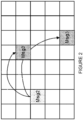
- the UE may retransmit message 3 if it has not received an acknowledgement or contention resolution message after a well-defined period of time. This can be achieved for example by using a timer, which would be started after the first message 3 is transmitted, and the UE would retransmit upon the timer expiry. The UE could in this case re-use the previously provided first or second UL grant (depending e.g. on the data size).
- the used frequency resources can be the same as in the initial grants or then shifted.
- the time resources provided in the first set of grants map to a later time as the initial transmission was lost.
- the used timer, possible shift in frequency resources and mapping of time resources can be configured in a cell or per UE (e.g.
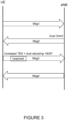
- only one DCI may be sent by eNB asking for the UE to retransmit message 3.
- the UE may combine information provided in the DCI with the information in the dual grants transmitted during previous step (i.e., in message 2 / RAR).
- this retransmission request DCI provides new time and frequency resources for the UE to use, where the rest of the information is taken from the dual grants sent by the eNB in the previous step.
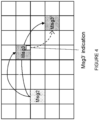
- this DCI provides two sets of such time/frequency resource separately for the first and the second UL grant.
- the provided information in the DCI can be some other parameter than time/frequency resource, or a combination of many parameters.
- the UE uses the resource in the second UL grant to transmit message 3, and this message 3 is lost.
- This case is similar to the first case described above, and the solutions are similar to the ones outlined for the first case. Specifically, there may be a fall back to Rel-13, an indication in DCI, a timer based solution, and separate search spaces.
- a similar timer-based solution is adopted as in the first case, and the UE may retransmit message 3 upon expiry of a timer.
- the UE may assume the previous UL grant except, for example, the timing which is determined based on an offset, expiry of a timer etc.
- the UE uses the resource in the second UL grant to transmit message 3, and this message 3 cannot be decoded correctly.
- the eNB may be certain that the UE uses the resource indicated in the second UL grant (e.g., the eNB detects significant higher energy in the UL resource indicated by the second UL grant than in the UL resource indicated by the first UL grant), and therefore, the eNB may not need to send dual UL grants.
- the eNB may also be certain that the UE has higher capability.
- the eNB when the eNB is certain that the UE is capable of using the second UL grant, for the retransmission of message 3, the eNB can either provide a new UL grant in the same way as the release 13 and release 14 case, or provide a new grant assuming UE is capable of early data. That is saying, for example, a larger TBS than the release 13 and release 14 case and potentially new MCS.
- a similar timer-based solution may be adopted as described above for the first case, and the UE may retransmit message 3 upon expiry of a timer.
- message 3' which is scheduled by the 2 nd UL grant
- an indication of the use of the UL resource of the 1 st UL grant is used (i.e., message 3).
- the resume ID should be both included in message 3 and message 3'.
- the same random number should be both included in message 3 and message 3'. That is saying the random number is generated once and included in both message 3 and message 3'.
- the size of the payload carried by message 3' is indicated in message 3.
- the indication in message 3' can be the exact payload size or a range of the payload size based on one or more thresholds. For example, in message 3 it can indicate whether the actual payload size in message 3' is larger or smaller than the allocated TBS in the second UL grant, or the actual payload size is larger or smaller than a predefined threshold X.
- the retransmission of message 3 and/or message 3' is not scheduled by using DCI but in a similar way as the random access response (RAR) message. That is instead of directly using a DCI schedule the retransmission of message 3, a DCI used to schedule NPDSCH/PDSCH that carriers the scheduling information (can be dual grants also, e.g., similar as the one in RAR in message 2) for the retransmission of message 3 and/or message 3'.
- RAR random access response
- the HARQ feedbacks for the message 3 transmissions and message 3' transmissions are handled independently.
- the eNB can provide dual UL grants via two DCIs to schedule the retransmission of message 3.
- the resource indicated in one of the DCIs is used for the retransmission of message 3 if for the initial message 3 transmission at the beginning the UE uses the resource indicated by the first UL grant
- the resource indicated in the other DCI is used for the retransmission of message 3' if for the initial message 3' transmission at the beginning the UE uses the resource indicated by the second UL grant.
- the DCI used to schedule the retransmission message 3' is in a different MPDCCH/NPDCCH search space than the one used to schedule the retransmission of message 3.
- the configurations of the MPDCCH/NPDCCH search spaces for the DCIs used to schedule the retransmission of message 3 and message 3' is given in the SI, or in the random access response message.
- the UE retransmits message 3 if it has not received an acknowledgement or contention resolution message after a period of time.
- This can be achieved for example by using a timer, which would be started after the first message 3 is transmitted and the UE would retransmit upon the timer expiry.
- the UE could in this case re-use the previously provided first or second UL grant (depending e.g. on the data size).
- the used frequency resources can be the same as in the initial grants or then shifted.
- the time resources provided in the first set of grants map to a later time as the initial transmission was lost.
- the used timer, possible shift in frequency resources and mapping of time resources can be configured in a cell or per UE (e.g.
- the DCI used to schedule the retransmission message 3' is in a different MPDCCH/NPDCCH search space than the one that schedule the retransmission of message 3.
- a timer-based solution like the one described above for the first cases (first instance) 1 (second instance) could also be possible, but if there is no feedback (i.e. no new grant) from the eNB, the UE cannot know if the message 3 transmission has gone through or not.
- a retransmission may be scheduled by the UE after a certain time period has passed, where the UE would retransmit message 3 (even the eNB already received it).
- the eNB may send an acknowledgement to the UE it has received message 3, but not for message 3', thus the UE could retransmit message 3' instead.
- message 3' there could be a similar but separate retransmission timer as for message 3.
- the eNB detects the UE uses the resource in the second UL grant to transmit message 3', and this message 3' cannot be decoded correctly.
- the solution in this scenario is the same as that for the second case, described above.
- the DCI there is a field to indicate whether the DCI is to allocate the UL resource for the retransmission of message 3 or message 3' or both at the same time.
- the network can indicate of partial of message 3' is retransmitted together with message 3, e.g., by providing a TBS that is larger than the one used by message 3, but smaller to accommodate all the payload in the original message 3'.
- network node refers to equipment capable, configured, arranged and/or operable to communicate directly or indirectly with a wireless device and/or with other network nodes or equipment in the wireless network to enable and/or provide wireless access to the wireless device and/or to perform other functions (e.g., administration) in the wireless network.
- network nodes include, but are not limited to, access points (APs) (e.g., radio access points), base stations (BSs) (e.g., radio base stations, Node Bs, evolved Node Bs (eNBs) and NR NodeBs (gNBs)).
- APs access points
- BSs base stations
- eNBs evolved Node Bs
- gNBs NR NodeBs
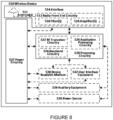
- network node 560 may comprise multiple different physical components that make up a single illustrated component (e.g., device readable medium 580 may comprise multiple separate hard drives as well as multiple RAM modules).
- Processing circuitry 570 is configured to perform any determining, calculating, or similar operations (e.g., certain obtaining operations) described herein as being provided by a network node. These operations performed by processing circuitry 570 may include processing information obtained by processing circuitry 570 by, for example, converting the obtained information into other information, comparing the obtained information or converted information to information stored in the network node, and/or performing one or more operations based on the obtained information or converted information, and as a result of said processing making a determination.
- processing information obtained by processing circuitry 570 by, for example, converting the obtained information into other information, comparing the obtained information or converted information to information stored in the network node, and/or performing one or more operations based on the obtained information or converted information, and as a result of said processing making a determination.
- Processing circuitry 570 may comprise a combination of one or more of a microprocessor, controller, microcontroller, central processing unit, digital signal processor, application-specific integrated circuit, field programmable gate array, or any other suitable computing device, resource, or combination of hardware, software and/or encoded logic operable to provide, either alone or in conjunction with other network node 560 components, such as device readable medium 580, network node 560 functionality.
- processing circuitry 570 may execute instructions stored in device readable medium 580 or in memory within processing circuitry 570. Such functionality may include providing any of the various wireless features, functions, or benefits discussed herein.
- processing circuitry 570 may include a system on a chip (SOC).
- SOC system on a chip
- processing circuitry 570 may include one or more of radio frequency (RF) transceiver circuitry 572 and baseband processing circuitry 574.
- radio frequency (RF) transceiver circuitry 572 and baseband processing circuitry 574 may be on separate chips (or sets of chips), boards, or units, such as radio units and digital units.
- part or all of RF transceiver circuitry 572 and baseband processing circuitry 574 may be on the same chip or set of chips, boards, or units.
- Device readable medium 580 may comprise any form of volatile or non-volatile computer readable memory including, without limitation, persistent storage, solid-state memory, remotely mounted memory, magnetic media, optical media, random access memory (RAM), read-only memory (ROM), mass storage media (for example, a hard disk), removable storage media (for example, a flash drive, a Compact Disk (CD) or a Digital Video Disk (DVD)), and/or any other volatile or non-volatile, non-transitory device readable and/or computer-executable memory devices that store information, data, and/or instructions that may be used by processing circuitry 570.
- volatile or non-volatile computer readable memory including, without limitation, persistent storage, solid-state memory, remotely mounted memory, magnetic media, optical media, random access memory (RAM), read-only memory (ROM), mass storage media (for example, a hard disk), removable storage media (for example, a flash drive, a Compact Disk (CD) or a Digital Video Disk (DVD)), and/or any other volatile or
- Interface 590 is used in the wired or wireless communication of signalling and/or data between network node 560, network 506, and/or WDs 510. As illustrated, interface 590 comprises port(s)/terminal(s) 594 to send and receive data, for example to and from network 506 over a wired connection. Interface 590 also includes radio front end circuitry 592 that may be coupled to, or in certain embodiments a part of, antenna 562. Radio front end circuitry 592 comprises filters 598 and amplifiers 596. Radio front end circuitry 592 may be connected to antenna 562 and processing circuitry 570. Radio front end circuitry may be configured to condition signals communicated between antenna 562 and processing circuitry 570.
- Radio front end circuitry 592 may receive digital data that is to be sent out to other network nodes or WDs via a wireless connection. Radio front end circuitry 592 may convert the digital data into a radio signal having the appropriate channel and bandwidth parameters using a combination of filters 598 and/or amplifiers 596. The radio signal may then be transmitted via antenna 562. Similarly, when receiving data, antenna 562 may collect radio signals which are then converted into digital data by radio front end circuitry 592. The digital data may be passed to processing circuitry 570. In other embodiments, the interface may comprise different components and/or different combinations of components.
- Antenna 562 may include one or more antennas, or antenna arrays, configured to send and/or receive wireless signals. Antenna 562 may be coupled to radio front end circuitry 590 and may be any type of antenna capable of transmitting and receiving data and/or signals wirelessly. In some embodiments, antenna 562 may comprise one or more omni-directional, sector or panel antennas operable to transmit/receive radio signals between, for example, 2 GHz and 66 GHz. An omni-directional antenna may be used to transmit/receive radio signals in any direction, a sector antenna may be used to transmit/receive radio signals from devices within a particular area, and a panel antenna may be a line of sight antenna used to transmit/receive radio signals in a relatively straight line. In some instances, the use of more than one antenna may be referred to as MIMO. In certain embodiments, antenna 562 may be separate from network node 560 and may be connectable to network node 560 through an interface or port.
- Antenna 562, interface 590, and/or processing circuitry 570 may be configured to perform any receiving operations and/or certain obtaining operations described herein as being performed by a network node. Any information, data and/or signals may be received from a wireless device, another network node and/or any other network equipment. Similarly, antenna 562, interface 590, and/or processing circuitry 570 may be configured to perform any transmitting operations described herein as being performed by a network node. Any information, data and/or signals may be transmitted to a wireless device, another network node and/or any other network equipment.
- Examples of a WD include, but are not limited to, a smart phone, a mobile phone, a cell phone, a voice over IP (VoIP) phone, a wireless local loop phone, a desktop computer, a personal digital assistant (PDA), a wireless cameras, a gaming console or device, a music storage device, a playback appliance, a wearable terminal device, a wireless endpoint, a mobile station, a tablet, a laptop, a laptop-embedded equipment (LEE), a laptop-mounted equipment (LME), a smart device, a wireless customer-premise equipment (CPE). a vehicle-mounted wireless terminal device, etc.
- VoIP voice over IP
- PDA personal digital assistant
- PDA personal digital assistant
- gaming console or device a wireless cameras
- a gaming console or device a music storage device
- a playback appliance a wearable terminal device
- a wireless endpoint a mobile station, a tablet, a laptop, a laptop-embedded equipment (LEE), a laptop
- Power source 536 may, in some embodiments, be in the form of a battery or battery pack. Other types of power sources, such as an external power source (e.g., an electricity outlet), photovoltaic devices or power cells, may also be used.
- WD 510 may further comprise power circuitry 537 for delivering power from power source 536 to the various parts of WD 510 which need power from power source 536 to carry out any functionality described or indicated herein.
- Power circuitry 537 may in certain embodiments comprise power management circuitry.
- Power circuitry 537 may additionally or alternatively be operable to receive power from an external power source; in which case WD 510 may be connectable to the external power source (such as an electricity outlet) via input circuitry or an interface such as an electrical power cable.
- FIGURE 9 illustrates an example UE 600, according to certain embodiments.
- a user equipment or UE 600 may not necessarily have a user in the sense of a human user who owns and/or operates the relevant device.
- a UE 600 may represent a device that is intended for sale to, or operation by, a human user but which may not, or which may not initially, be associated with a specific human user (e.g., a smart sprinkler controller).
- a UE 600 may represent a device that is not intended for sale to, or operation by, an end user but which may be associated with or operated for the benefit of a user (e.g., a smart power meter).
- Storage medium 621 may be configured to include memory such as RAM, ROM, programmable read-only memory (PROM), erasable programmable read-only memory (EPROM), electrically erasable programmable read-only memory (EEPROM), magnetic disks, optical disks, floppy disks, hard disks, removable cartridges, or flash drives.
- storage medium 621 may be configured to include operating system 623, application program 625 such as a web browser application, a widget or gadget engine or another application, and data file 627.
- Storage medium 621 may store, for use by UE 600, any of a variety of various operating systems or combinations of operating systems.
- Virtualization environment 700 comprises general-purpose or special-purpose network hardware devices 730 comprising a set of one or more processors or processing circuitry 760, which may be commercial off-the-shelf (COTS) processors, dedicated Application Specific Integrated Circuits (ASICs), or any other type of processing circuitry including digital or analog hardware components or special purpose processors.
- processors or processing circuitry 760 which may be commercial off-the-shelf (COTS) processors, dedicated Application Specific Integrated Circuits (ASICs), or any other type of processing circuitry including digital or analog hardware components or special purpose processors.
- Each hardware device may comprise memory 790-1 which may be non-persistent memory for temporarily storing instructions 795 or software executed by processing circuitry 760.
- Each hardware device may comprise one or more network interface controllers (NICs) 770, also known as network interface cards, which include physical network interface 780.
- NICs network interface controllers
- Each hardware device may also include non-transitory, persistent, machine-readable storage media 790-2 having stored therein software 795 and/or instructions executable by processing circuitry 760.
- Software 795 may include any type of software including software for instantiating one or more virtualization layers 750 (also referred to as hypervisors), software to execute virtual machines 740 as well as software allowing it to execute functions, features and/or benefits described in relation with some embodiments described herein.
- Virtual machines 740 comprise virtual processing, virtual memory, virtual networking or interface and virtual storage, and may be run by a corresponding virtualization layer 750 or hypervisor. Different embodiments of the instance of virtual appliance 720 may be implemented on one or more of virtual machines 740, and the implementations may be made in different ways.
- control system 7230 which may alternatively be used for communication between the hardware nodes 730 and radio units 7200.
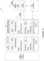
- FIGURE 12 illustrates a host computer communicating via a base station with a user equipment over a partially wireless connection, according to certain embodiments.
- host computer 910 comprises hardware 915 including communication interface 916 configured to set up and maintain a wired or wireless connection with an interface of a different communication device of communication system 900.
- Host computer 910 further comprises processing circuitry 918, which may have storage and/or processing capabilities.
- processing circuitry 918 may comprise one or more programmable processors, application-specific integrated circuits, field programmable gate arrays or combinations of these (not shown) adapted to execute instructions.
- host computer 910, base station 920 and UE 930 illustrated in FIGURE 12 may be similar or identical to host computer 830, one of base stations 812a, 812b, 812c and one of UEs 891, 892 of FIGURE 11 , respectively.
- the inner workings of these entities may be as shown in FIGURE 12 and independently, the surrounding network topology may be that of FIGURE 11 .
- OTT connection 950 has been drawn abstractly to illustrate the communication between host computer 910 and UE 930 via base station 920, without explicit reference to any intermediary devices and the precise routing of messages via these devices.
- Network infrastructure may determine the routing, which it may be configured to hide from UE 930 or from the service provider operating host computer 910, or both. While OTT connection 950 is active, the network infrastructure may further take decisions by which it dynamically changes the routing (e.g., on the basis of load balancing consideration or reconfiguration of the network).
- Wireless connection 970 between UE 930 and base station 920 is in accordance with the teachings of the embodiments described throughout this disclosure.
- One or more of the various embodiments improve the performance of OTT services provided to UE 930 using OTT connection 950, in which wireless connection 970 forms the last segment. More precisely, the teachings of these embodiments may improve the use of radio resources and thereby provide benefits such as improved responsiveness, lower latency, reduced data usage.
- step 1030 the base station transmits to the UE the user data which was carried in the transmission that the host computer initiated, in accordance with the teachings of the embodiments described throughout this disclosure.
- step 1040 the UE executes a client application associated with the host application executed by the host computer.
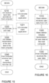
- FIGURE 15 is a flowchart illustrating another example method implemented in a communication system, in accordance with one embodiment.
- the communication system includes a host computer, a base station and a UE which may be those described with reference to FIGURES 11 and 12 .
- the UE receives input data provided by the host computer.
- the UE provides user data.
- substep 1221 (which may be optional) of step 1220, the UE provides the user data by executing a client application.
- the term unit may have conventional meaning in the field of electronics, electrical devices and/or electronic devices and may include, for example, electrical and/or electronic circuitry, devices, modules, processors, memories, logic solid state and/or discrete devices, computer programs or instructions for carrying out respective tasks, procedures, computations, outputs, and/or displaying functions, and so on, as such as those that are described herein.
- the message 2 includes a random access response message comprising the plurality of transport block sizes allocated to the wireless device for the first transmission of the message 3.
- the DCI comprises at least one of a time resource and a frequency resource for use in the retransmission of the message 3.
- the at least one of the time resource and the frequency resource for use in the retransmission of the message 3 has an identical size to at least one of a time resource and a frequency resource used for an initial transmission of the message 3.
- the at least one of the time resource and the frequency resource for use in the retransmission of the message 3 has a different size from at least one of a time resource and a frequency resource used for an initial transmission of the message 3.
- the at least one of the time resource and the frequency resource for use in the retransmission of the message 3 is shifted from at least one of a time resource and a frequency resource used for the initial transmission of the message 3.
- FIGURE 19 illustrates example of signalling for uplink data transmission in Msg5 using RRC suspend/resume (User plane CIoT EPS optimization).
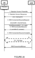
- FIGURE 20 illustrates early UL data in Message 3 using RRC Resume. Specifically, FIGURE 20 shows the message flow for early data in Message 3 together with RRCConnectionResumeRequest, with possible further UL/DL data transmissions. For more details on the RRC procedures and security details, see R2-1708630, "Bearer Setup and Security Considerations for Early Data in MTC", RAN2#99, source Ericsson. Early data transmission in Message 3 vs data transmission in Msg5
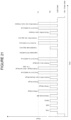
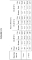
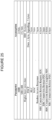
- FIGURE 22 illustrates results for early data transmission in Message 3 and Message 4 (MO event).
- FIGURE 23 illustrates results for early data in Message 4 (MT event).
- a first proposal may be that details for early data transmission support for MT data in Message 4 may be specified. Note that there is a difference in where the first DL data are sent between the UL and DL triggered case: For DL triggered or MT traffic case the DL data can be sent in Message 4, but in the UL triggered case it might not be possible to send possible DL answer to UL data back in Message 4 if there is considerable delay (such as 1000 ms as used in some models. In this case the DL answer to UL triggered data transmission would be sent in a later message after Message 4.
- FIGURE 24 summarizes the results of downlink transmission only (Message 4).
- FIGURES 26 and 27 present the radio related assumptions used for evaluation of latency and battery life performance. For power consumption evaluation we use average values, where available, and for latency calculation the 90 th percentile values.
Landscapes
- Engineering & Computer Science (AREA)
- Signal Processing (AREA)
- Computer Networks & Wireless Communication (AREA)
- Mobile Radio Communication Systems (AREA)
Claims (15)
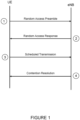
- Verfahren, das von einer drahtlosen Vorrichtung (510) durchgeführt wird, zur Neuübertragung einer Nachricht 3, wobei das Verfahren Folgendes umfasst:Empfangen einer Nachricht 2, die eine erste Uplink-Freigabe, UL-Freigabe, die eine erste Transportblockgröße angibt, und eine zweite UL-Freigabe umfasst, die eine zweite Transportblockgröße angibt, von einer Basisstation (560),Übertragen einer ersten Übertragung einer Nachricht 3 an die Basisstation (560), wobei die Nachricht 3 Informationen zum Aufbauen oder Wiederaufnehmen einer Verbindung zwischen der drahtlosen Vorrichtung (510) und der Basisstation (560) und Benutzerdaten umfasst;Empfangen von Downlink-Steuerinformationen, DCI, von der Basisstation (560), die eine Angabe für die drahtlose Vorrichtung zum Neuübertragen der Nachricht 3 umfassen, wobei die DCI von der drahtlosen Vorrichtung (510) basierend auf vorherigen Informationen interpretiert werden, die in der Nachricht 2 von der Basisstation (560) empfangen wurden;Auswählen einer Transportblockgröße von der ersten Transportblockgröße und der zweiten Transportblockgröße zur Neuübertragung der Nachricht 3, wobei die Neuübertragung der Nachricht 3 entweder nur die Informationen zum Aufbauen oder Wiederaufnehmen der Verbindung oder die Informationen zum Aufbauen und Wiederaufnehmen der Verbindung und Benutzerdaten umfasst, die an die Basisstation (560) gesendet werden sollen; undNeuübertragen der Nachricht 3 unter Verwendung der ausgewählten Transportblockgröße.
- Verfahren nach Anspruch 1, ferner umfassend Empfangen einer Nachricht 4, die eine Konfliktauflösungsnachricht umfasst, die die Verbindung zwischen der drahtlosen Vorrichtung (510) und der Basisstation (560) herstellt, von der Basisstation (560), wobei die Nachricht 4 nach der Neuübertragung der Nachricht 3 empfangen wird.
- Verfahren nach einem der Ansprüche 1 bis 2, wobei die erste Übertragung der Nachricht 3 unter Verwendung der ausgewählten Transportblockgröße übertragen wird.
- Verfahren nach einem der Ansprüche 1 bis 3, wobei die erste Übertragung der Nachricht 3 unter Verwendung einer Transportblockgröße übertragen wird, die sich von der ausgewählten Transportblockgröße, die zur Neuübertragung der Nachricht 3 verwendet wird, unterscheidet.
- Verfahren nach einem der Ansprüche 1 bis 4, ferner umfassend:Starten eines Zeitgebers, der mit der ersten Übertragung der Nachricht 3 assoziiert ist;Bestimmen, dass der Zeitgeber abgelaufen ist, bevor eine Bestätigung von der Basisstation (560) empfangen wird, die angibt, dass die Basisstation (560) die erste Übertragung der Nachricht empfangen hat; undSenden der Neuübertragung der Nachricht 3 in Reaktion auf das Bestimmen, dass der Zeitgeber vor dem Empfang einer Bestätigung von der Basisstation (560) abgelaufen ist.
- Verfahren nach einem der Ansprüche 1 bis 5, wobei die DCI mindestens eine von einer Zeitressource und einer Frequenzressource zur Verwendung bei der Neuübertragung der Nachricht 3 umfassen.
- Verfahren nach einem der Ansprüche 1 bis 6, wobei die DCI mindestens eine Zeitressource und eine Frequenzressource für jede von der ersten Transportblockgröße und der zweiten Transportblockgröße umfassen.
- Verfahren, das von einer Basisstation (560) durchgeführt wird, zum Empfangen einer Nachricht 3, wobei das Verfahren Folgendes umfasst:Übertragen einer Nachricht 2, die eine erste Uplink-Freigabe, UL-Freigabe, die eine erste Transportblockgröße angibt, und eine zweite UL-Freigabe umfasst, die eine zweite Transportblockgröße angibt, an eine drahtlose Vorrichtung (510),Übertragen von Downlink-Steuerinformationen, DCI, an die drahtlose Vorrichtung (510), um eine Neuübertragung einer Nachricht 3 zu disponieren, wobei die DCI von der drahtlosen Vorrichtung (510) basierend auf dem Inhalt der Nachricht 2 interpretiert werden, wobei die DCI eine Angabe für die drahtlose Vorrichtung zum Neuübertragen der Nachricht 3 umfassen; undEmpfangen der Neuübertragung der Nachricht 3 von der drahtlosen Vorrichtung (510), wobei die Neuübertragung der Nachricht 3 basierend auf einer ausgewählten Transportblockgröße von der ersten Transportblockgröße und der zweiten Transportblockgröße übertragen wird, wobei die Neuübertragung der Nachricht 3 entweder nur Informationen zum Aufbauen oder Wiederaufnehmen einer Verbindung zwischen der drahtlosen Vorrichtung (510) und der Basisstation (560) umfasst oder sowohl Informationen zum Aufbauen oder Wiederaufnehmen der Verbindung zwischen der drahtlosen Vorrichtung (510) und der Basisstation (560) als auch Benutzerdaten umfasst.
- Verfahren nach Anspruch 8, ferner umfassend:vor dem Übertragen der DCI zum Disponieren der Neuübertragung der Nachricht 3 Empfangen einer Erstübertragung der Nachricht 3; undBestimmen, dass mindestens ein Abschnitt der Erstüberragung der Nachricht 3 nicht decodiert werden kann.
- Verfahren nach einem der Ansprüche 8 bis 9, wobei die DCI mindestens eine von einer Zeitressource und einer Frequenzressource zur Verwendung bei der Neuübertragung der Nachricht 3 umfassen.
- Verfahren nach einem der Ansprüche 8 bis 10, wobei die DCI mindestens eine Zeitressource und eine Frequenzressource für jede von der ersten Transportblockgröße und der zweiten Transportblockgröße umfassen.
- Drahtlose Vorrichtung (510), umfassend:
Verarbeitungsschaltungsanordnung, die zu Folgendem konfiguriert ist:Empfangen einer Nachricht 2, die eine erste Uplink-Freigabe, UL-Freigabe, die eine erste Transportblockgröße angibt, und eine zweite UL-Freigabe umfasst, die eine zweite Transportblockgröße angibt, von einer Basisstation (560),Übertragen einer ersten Übertragung einer Nachricht 3 an die Basisstation (560), wobei die Nachricht 3 Informationen zum Aufbauen oder Wiederaufnehmen einer Verbindung zwischen der drahtlosen Vorrichtung (510) und der Basisstation (560) und Benutzerdaten umfasst;Empfangen von Downlink-Steuerinformationen, DCI, von der Basisstation (560), die eine Angabe für die drahtlose Vorrichtung zum Neuübertragen der Nachricht 3 umfassen, wobei die DCI von der drahtlosen Vorrichtung (510) basierend auf vorherigen Informationen interpretiert werden, die in der Nachricht 2 von der Basisstation (560) empfangen wurden;Auswählen einer Transportblockgröße von der ersten Transportblockgröße und der zweiten Transportblockgröße zur Neuübertragung der Nachricht 3, wobei die Neuübertragung der Nachricht 3 entweder nur die Informationen zum Aufbauen oder Wiederaufnehmen der Verbindung zwischen der drahtlosen Verbindung (510) und der Basisstation (560) oder die Informationen zum Aufbauen und Wiederaufnehmen der Verbindung zwischen der drahtlosen Vorrichtung (510) und der Basisstation (560) und Benutzerdaten umfasst, die an die Basisstation (560) gesendet werden sollen; undNeuübertragen der Nachricht 3 unter Verwendung der ausgewählten Transportblockgröße; undLeistungsversorgungsschaltungsanordnung, die zum Versorgen der drahtlosen Vorrichtung (510) mit Leistung konfiguriert ist. - Drahtlose Vorrichtung (510) nach Anspruch 12, wobei die drahtlose Vorrichtung (510) zum Durchführen des Verfahrens nach einem der Ansprüche 2 bis 7 ausgelegt ist.
- Basisstation (560), umfassend:
Verarbeitungsschaltungsanordnung, die zu Folgendem konfiguriert ist:Übertragen einer Nachricht 2, die eine erste Uplink-Freigabe, UL-Freigabe, die eine erste Transportblockgröße angibt, und eine zweite UL-Freigabe umfasst, die eine zweite Transportblockgröße angibt, an eine drahtlose Vorrichtung (510),Übertragen von Downlink-Steuerinformationen, DCI, an die drahtlose Vorrichtung (510), um eine Neuübertragung einer Nachricht 3 zu disponieren, wobei die DCI von der drahtlosen Vorrichtung (510) basierend auf dem Inhalt der Nachricht 2 interpretiert werden, wobei die DCI eine Angabe für die drahtlose Vorrichtung zum Neuübertragen der Nachricht 3 umfassen; undEmpfangen der Neuübertragung der Nachricht 3 von der drahtlosen Vorrichtung (510), wobei die Neuübertragung der Nachricht 3 basierend auf einer ausgewählten Transportblockgröße von der ersten Transportblockgröße und der zweiten Transportblockgröße übertragen wird, wobei die Neuübertragung der Nachricht 3 entweder nur Informationen zum Aufbauen oder Wiederaufnehmen einer Verbindung zwischen der drahtlosen Vorrichtung (510) und der Basisstation (560) umfasst oder sowohl Informationen zum Aufbauen oder Wiederaufnehmen der Verbindung zwischen der drahtlosen Vorrichtung (510) und der Basisstation (560) als auch Benutzerdaten umfasst; undLeistungsversorgungsschaltungsanordnung, die zum Versorgen der drahtlosen Vorrichtung (510) mit Leistung konfiguriert ist. - Basisstation (560) nach Anspruch 14, wobei die Basisstation (560) zum Durchführen des Verfahrens nach einem der Ansprüche 9 bis 11 ausgelegt ist.
Applications Claiming Priority (2)
| Application Number | Priority Date | Filing Date | Title |
|---|---|---|---|
| US201762544130P | 2017-08-11 | 2017-08-11 | |
| PCT/IB2018/056048 WO2019030723A1 (en) | 2017-08-11 | 2018-08-10 | EARLY MESSAGE DATA RETRANSMISSION 3 |
Publications (2)
| Publication Number | Publication Date |
|---|---|
| EP3665818A1 EP3665818A1 (de) | 2020-06-17 |
| EP3665818B1 true EP3665818B1 (de) | 2025-04-09 |
Family
ID=63683235
Family Applications (1)
| Application Number | Title | Priority Date | Filing Date |
|---|---|---|---|
| EP18774111.1A Active EP3665818B1 (de) | 2017-08-11 | 2018-08-10 | Frühe datenwiederübertragung von message 3 |
Country Status (7)
| Country | Link |
|---|---|
| US (1) | US11785660B2 (de) |
| EP (1) | EP3665818B1 (de) |
| CN (1) | CN111095838B (de) |
| AR (1) | AR112736A1 (de) |
| BR (1) | BR112020002947A2 (de) |
| MX (1) | MX2020001380A (de) |
| WO (1) | WO2019030723A1 (de) |
Families Citing this family (9)
| Publication number | Priority date | Publication date | Assignee | Title |
|---|---|---|---|---|
| US12010689B2 (en) * | 2018-09-27 | 2024-06-11 | Lg Electronics Inc. | Method and system for transmitting and receiving data in narrow band wireless communication system |
| CN111182630B (zh) * | 2018-11-09 | 2022-11-11 | 华为技术有限公司 | 数据接收和发送的方法、设备及系统 |
| JP7488471B2 (ja) * | 2019-01-16 | 2024-05-22 | 富士通株式会社 | 通信装置、第2通信装置、及び通信システム |
| BR112021021005A2 (pt) * | 2019-05-02 | 2021-12-14 | Ntt Docomo Inc | Equipamento de usuário e aparelho de estação base |
| EP3979703A4 (de) * | 2019-06-27 | 2022-09-28 | Guangdong Oppo Mobile Telecommunications Corp., Ltd. | Datenübertragungsverfahren, vorrichtung und kommunikationsvorrichtung |
| US11683815B2 (en) * | 2020-05-15 | 2023-06-20 | Qualcomm Incorporated | Piggyback downlink control information (DCI) scheduling limit |
| US11950252B2 (en) * | 2020-07-02 | 2024-04-02 | Qualcomm Incorporated | Early termination of uplink communication repetitions with multiple transport blocks |
| CN117280836A (zh) * | 2021-07-30 | 2023-12-22 | Oppo广东移动通信有限公司 | 随机接入方法、装置、设备及存储介质 |
| CN114364050B (zh) * | 2021-12-31 | 2023-11-14 | 赛特斯信息科技股份有限公司 | 用户随机接入基站的方法 |
Family Cites Families (16)
| Publication number | Priority date | Publication date | Assignee | Title |
|---|---|---|---|---|
| EP2263341B1 (de) | 2008-04-14 | 2018-09-19 | Amazon Technologies, Inc. | Verfahren und vorrichtung zur durchürung von direktzugriffsprozeduren |
| EP2849483B1 (de) * | 2012-06-06 | 2019-08-21 | Huawei Technologies Co., Ltd. | Verfahren, endgerät und basisstation (bs) zur neuübertragung einer nachricht |
| WO2015137632A1 (en) | 2014-03-11 | 2015-09-17 | Lg Electronics Inc. | Method for allocating temporary identifier to terminal in random access procedure in wireless communication system and apparatus tehrefor |
| US9497926B2 (en) * | 2014-03-17 | 2016-11-22 | Afimilk Agricultural Cooperative Ltd. | System and method for treating livestock |
| US10009926B2 (en) * | 2014-07-11 | 2018-06-26 | Qualcomm Incorporated | Methods and apparatus for connectionless access |
| US20160270038A1 (en) * | 2015-03-11 | 2016-09-15 | Samsung Electronics Co., Ltd | Transmissions of downlink control channels for low cost ues |
| CN108605331A (zh) | 2016-02-04 | 2018-09-28 | 株式会社Ntt都科摩 | 用户终端、无线基站以及无线通信方法 |
| CN109314982B (zh) * | 2016-06-10 | 2022-03-01 | Lg 电子株式会社 | 无线通信系统中减少时延的信号发送和接收方法及其装置 |
| JP2020505833A (ja) * | 2017-01-13 | 2020-02-20 | 華為技術有限公司Huawei Technologies Co.,Ltd. | チャネルリスニング方法および装置 |
| EP3598680B1 (de) * | 2017-03-17 | 2021-11-24 | LG Electronics Inc. | Verfahren und vorrichtung, über die ein endgerät in einem drahtloskommunikationssystem daten empfängt |
| US10652866B2 (en) * | 2017-03-20 | 2020-05-12 | Huawei Technologies Co., Ltd. | Systems and methods for supporting asynchronous uplink HARQ and multiple simultaneous transmissions |
| US10524294B2 (en) * | 2017-05-04 | 2019-12-31 | Ofinno, Llc | Scheduling request transmission |
| JP2019004320A (ja) * | 2017-06-15 | 2019-01-10 | シャープ株式会社 | 基地局装置、端末装置およびその通信方法 |
| US11147064B2 (en) * | 2017-09-07 | 2021-10-12 | Ofinno, Llc | Resource selection for data multiplexing |
| KR102420721B1 (ko) * | 2017-09-08 | 2022-07-18 | 삼성전자 주식회사 | 통신 또는 방송 시스템에서 전송블록 크기 결정 방법 및 장치 |
| US11523422B2 (en) * | 2017-11-16 | 2022-12-06 | Lenovo (Singapore) Pte. Ltd. | Determining transport block generation timing of an uplink transmission |
-
2018
- 2018-08-10 EP EP18774111.1A patent/EP3665818B1/de active Active
- 2018-08-10 CN CN201880052264.8A patent/CN111095838B/zh active Active
- 2018-08-10 WO PCT/IB2018/056048 patent/WO2019030723A1/en not_active Ceased
- 2018-08-10 US US16/325,173 patent/US11785660B2/en active Active
- 2018-08-10 BR BR112020002947-5A patent/BR112020002947A2/pt unknown
- 2018-08-10 MX MX2020001380A patent/MX2020001380A/es unknown
- 2018-08-13 AR ARP180102296A patent/AR112736A1/es active IP Right Grant
Also Published As
| Publication number | Publication date |
|---|---|
| BR112020002947A2 (pt) | 2020-08-11 |
| CN111095838B (zh) | 2022-08-19 |
| US11785660B2 (en) | 2023-10-10 |
| WO2019030723A1 (en) | 2019-02-14 |
| MX2020001380A (es) | 2020-03-09 |
| AR112736A1 (es) | 2019-12-04 |
| EP3665818A1 (de) | 2020-06-17 |
| US20220418029A1 (en) | 2022-12-29 |
| CN111095838A (zh) | 2020-05-01 |
Similar Documents
| Publication | Publication Date | Title |
|---|---|---|
| EP3834337B1 (de) | Uplink-planungsberechtigung für mehrere gemeinsam genutzte physikalische uplink-kanäle | |
| EP3791654B1 (de) | Fallback für frühe datenübertragung mit wahlfreiem zugriff | |
| EP3857756B1 (de) | Signalisierung zur wiederholung | |
| EP4104342B1 (de) | Bedingtes handhaben eines hybriden automatischen wiederholungsaufforderungsprozesses in einem konfigurationsberechtigungsaktivierungsverfahren | |
| EP3665818B1 (de) | Frühe datenwiederübertragung von message 3 | |
| EP3968718A1 (de) | Zeitbereichsressourcenzuweisung für einen gemeinsam genutzten downlink-kanal | |
| EP3925125B1 (de) | Verfahren zur harq-codebuch-bestimmung für kommunikation mit niedriger latenz | |
| EP3858076B1 (de) | Frühe datensendung für zufallszugriffsverfahren | |
| US12047996B2 (en) | Scheduling information for transmission | |
| US20220183061A1 (en) | Transmitting and receiving an indication | |
| EP4243472A2 (de) | Sicherer transport von nutzdaten über die steuerebene | |
| US12335046B2 (en) | HARQ RTT timer adjustment for multi-TB scheduling | |
| EP3585124B1 (de) | Verfahren zur zeitbereichsressourcenzuweisung für eine msg3-übertragung bei einer random-access-prozedur | |
| EP3881642A1 (de) | Nas-as-interaktion für frühe datenübertragung | |
| US11510133B2 (en) | System information update for NR-U | |
| WO2022060272A1 (en) | Methods of reporting information collected by a communication device and related devices and nodes | |
| HK40026037B (zh) | 消息3的早期资料重传 | |
| HK40026037A (en) | Early data retransmission of message 3 |
Legal Events
| Date | Code | Title | Description |
|---|---|---|---|
| STAA | Information on the status of an ep patent application or granted ep patent |
Free format text: STATUS: UNKNOWN |
|
| STAA | Information on the status of an ep patent application or granted ep patent |
Free format text: STATUS: THE INTERNATIONAL PUBLICATION HAS BEEN MADE |
|
| PUAI | Public reference made under article 153(3) epc to a published international application that has entered the european phase |
Free format text: ORIGINAL CODE: 0009012 |
|
| STAA | Information on the status of an ep patent application or granted ep patent |
Free format text: STATUS: REQUEST FOR EXAMINATION WAS MADE |
|
| 17P | Request for examination filed |
Effective date: 20200120 |
|
| AK | Designated contracting states |
Kind code of ref document: A1 Designated state(s): AL AT BE BG CH CY CZ DE DK EE ES FI FR GB GR HR HU IE IS IT LI LT LU LV MC MK MT NL NO PL PT RO RS SE SI SK SM TR |
|
| AX | Request for extension of the european patent |
Extension state: BA ME |
|
| DAV | Request for validation of the european patent (deleted) | ||
| DAX | Request for extension of the european patent (deleted) | ||
| STAA | Information on the status of an ep patent application or granted ep patent |
Free format text: STATUS: EXAMINATION IS IN PROGRESS |
|
| 17Q | First examination report despatched |
Effective date: 20210512 |
|
| REG | Reference to a national code |
Ref country code: DE Ref legal event code: R079 Free format text: PREVIOUS MAIN CLASS: H04L0001180000 Ipc: H04L0001080000 Ref document number: 602018080968 Country of ref document: DE |
|
| GRAP | Despatch of communication of intention to grant a patent |
Free format text: ORIGINAL CODE: EPIDOSNIGR1 |
|
| STAA | Information on the status of an ep patent application or granted ep patent |
Free format text: STATUS: GRANT OF PATENT IS INTENDED |
|
| RIC1 | Information provided on ipc code assigned before grant |
Ipc: H04W 74/0833 20240101ALN20250102BHEP Ipc: H04L 5/00 20060101ALI20250102BHEP Ipc: H04L 1/1867 20230101ALI20250102BHEP Ipc: H04L 1/08 20060101AFI20250102BHEP |
|
| INTG | Intention to grant announced |
Effective date: 20250124 |
|
| GRAS | Grant fee paid |
Free format text: ORIGINAL CODE: EPIDOSNIGR3 |
|
| GRAA | (expected) grant |
Free format text: ORIGINAL CODE: 0009210 |
|
| STAA | Information on the status of an ep patent application or granted ep patent |
Free format text: STATUS: THE PATENT HAS BEEN GRANTED |
|
| AK | Designated contracting states |
Kind code of ref document: B1 Designated state(s): AL AT BE BG CH CY CZ DE DK EE ES FI FR GB GR HR HU IE IS IT LI LT LU LV MC MK MT NL NO PL PT RO RS SE SI SK SM TR |
|
| REG | Reference to a national code |
Ref country code: GB Ref legal event code: FG4D |
|
| REG | Reference to a national code |
Ref country code: CH Ref legal event code: EP |
|
| REG | Reference to a national code |
Ref country code: DE Ref legal event code: R096 Ref document number: 602018080968 Country of ref document: DE |
|
| REG | Reference to a national code |
Ref country code: IE Ref legal event code: FG4D |
|
| REG | Reference to a national code |
Ref country code: NL Ref legal event code: MP Effective date: 20250409 |
|
| PG25 | Lapsed in a contracting state [announced via postgrant information from national office to epo] |
Ref country code: NL Free format text: LAPSE BECAUSE OF FAILURE TO SUBMIT A TRANSLATION OF THE DESCRIPTION OR TO PAY THE FEE WITHIN THE PRESCRIBED TIME-LIMIT Effective date: 20250409 |
|
| REG | Reference to a national code |
Ref country code: AT Ref legal event code: MK05 Ref document number: 1784530 Country of ref document: AT Kind code of ref document: T Effective date: 20250409 |
|
| PG25 | Lapsed in a contracting state [announced via postgrant information from national office to epo] |
Ref country code: PT Free format text: LAPSE BECAUSE OF FAILURE TO SUBMIT A TRANSLATION OF THE DESCRIPTION OR TO PAY THE FEE WITHIN THE PRESCRIBED TIME-LIMIT Effective date: 20250811 Ref country code: ES Free format text: LAPSE BECAUSE OF FAILURE TO SUBMIT A TRANSLATION OF THE DESCRIPTION OR TO PAY THE FEE WITHIN THE PRESCRIBED TIME-LIMIT Effective date: 20250409 Ref country code: FI Free format text: LAPSE BECAUSE OF FAILURE TO SUBMIT A TRANSLATION OF THE DESCRIPTION OR TO PAY THE FEE WITHIN THE PRESCRIBED TIME-LIMIT Effective date: 20250409 |
|
| PGFP | Annual fee paid to national office [announced via postgrant information from national office to epo] |
Ref country code: DE Payment date: 20250827 Year of fee payment: 8 |
|
| REG | Reference to a national code |
Ref country code: LT Ref legal event code: MG9D |
|
| PG25 | Lapsed in a contracting state [announced via postgrant information from national office to epo] |
Ref country code: GR Free format text: LAPSE BECAUSE OF FAILURE TO SUBMIT A TRANSLATION OF THE DESCRIPTION OR TO PAY THE FEE WITHIN THE PRESCRIBED TIME-LIMIT Effective date: 20250710 Ref country code: NO Free format text: LAPSE BECAUSE OF FAILURE TO SUBMIT A TRANSLATION OF THE DESCRIPTION OR TO PAY THE FEE WITHIN THE PRESCRIBED TIME-LIMIT Effective date: 20250709 |
|
| PG25 | Lapsed in a contracting state [announced via postgrant information from national office to epo] |
Ref country code: PL Free format text: LAPSE BECAUSE OF FAILURE TO SUBMIT A TRANSLATION OF THE DESCRIPTION OR TO PAY THE FEE WITHIN THE PRESCRIBED TIME-LIMIT Effective date: 20250409 |
|
| PG25 | Lapsed in a contracting state [announced via postgrant information from national office to epo] |
Ref country code: BG Free format text: LAPSE BECAUSE OF FAILURE TO SUBMIT A TRANSLATION OF THE DESCRIPTION OR TO PAY THE FEE WITHIN THE PRESCRIBED TIME-LIMIT Effective date: 20250409 |
|
| PGFP | Annual fee paid to national office [announced via postgrant information from national office to epo] |
Ref country code: GB Payment date: 20250827 Year of fee payment: 8 |
|
| PG25 | Lapsed in a contracting state [announced via postgrant information from national office to epo] |
Ref country code: HR Free format text: LAPSE BECAUSE OF FAILURE TO SUBMIT A TRANSLATION OF THE DESCRIPTION OR TO PAY THE FEE WITHIN THE PRESCRIBED TIME-LIMIT Effective date: 20250409 |
|
| PG25 | Lapsed in a contracting state [announced via postgrant information from national office to epo] |
Ref country code: AT Free format text: LAPSE BECAUSE OF FAILURE TO SUBMIT A TRANSLATION OF THE DESCRIPTION OR TO PAY THE FEE WITHIN THE PRESCRIBED TIME-LIMIT Effective date: 20250409 |
|
| PG25 | Lapsed in a contracting state [announced via postgrant information from national office to epo] |
Ref country code: RS Free format text: LAPSE BECAUSE OF FAILURE TO SUBMIT A TRANSLATION OF THE DESCRIPTION OR TO PAY THE FEE WITHIN THE PRESCRIBED TIME-LIMIT Effective date: 20250709 |
|
| PG25 | Lapsed in a contracting state [announced via postgrant information from national office to epo] |
Ref country code: IS Free format text: LAPSE BECAUSE OF FAILURE TO SUBMIT A TRANSLATION OF THE DESCRIPTION OR TO PAY THE FEE WITHIN THE PRESCRIBED TIME-LIMIT Effective date: 20250809 |
|
| PG25 | Lapsed in a contracting state [announced via postgrant information from national office to epo] |
Ref country code: LV Free format text: LAPSE BECAUSE OF FAILURE TO SUBMIT A TRANSLATION OF THE DESCRIPTION OR TO PAY THE FEE WITHIN THE PRESCRIBED TIME-LIMIT Effective date: 20250409 |
|
| REG | Reference to a national code |
Ref country code: DE Ref legal event code: R097 Ref document number: 602018080968 Country of ref document: DE |
|
| PG25 | Lapsed in a contracting state [announced via postgrant information from national office to epo] |
Ref country code: DK Free format text: LAPSE BECAUSE OF FAILURE TO SUBMIT A TRANSLATION OF THE DESCRIPTION OR TO PAY THE FEE WITHIN THE PRESCRIBED TIME-LIMIT Effective date: 20250409 Ref country code: SM Free format text: LAPSE BECAUSE OF FAILURE TO SUBMIT A TRANSLATION OF THE DESCRIPTION OR TO PAY THE FEE WITHIN THE PRESCRIBED TIME-LIMIT Effective date: 20250409 |
|
| PG25 | Lapsed in a contracting state [announced via postgrant information from national office to epo] |
Ref country code: CZ Free format text: LAPSE BECAUSE OF FAILURE TO SUBMIT A TRANSLATION OF THE DESCRIPTION OR TO PAY THE FEE WITHIN THE PRESCRIBED TIME-LIMIT Effective date: 20250409 |
|
| PG25 | Lapsed in a contracting state [announced via postgrant information from national office to epo] |
Ref country code: EE Free format text: LAPSE BECAUSE OF FAILURE TO SUBMIT A TRANSLATION OF THE DESCRIPTION OR TO PAY THE FEE WITHIN THE PRESCRIBED TIME-LIMIT Effective date: 20250409 |
|
| PG25 | Lapsed in a contracting state [announced via postgrant information from national office to epo] |
Ref country code: RO Free format text: LAPSE BECAUSE OF FAILURE TO SUBMIT A TRANSLATION OF THE DESCRIPTION OR TO PAY THE FEE WITHIN THE PRESCRIBED TIME-LIMIT Effective date: 20250409 Ref country code: SK Free format text: LAPSE BECAUSE OF FAILURE TO SUBMIT A TRANSLATION OF THE DESCRIPTION OR TO PAY THE FEE WITHIN THE PRESCRIBED TIME-LIMIT Effective date: 20250409 |
|
| PG25 | Lapsed in a contracting state [announced via postgrant information from national office to epo] |
Ref country code: IT Free format text: LAPSE BECAUSE OF FAILURE TO SUBMIT A TRANSLATION OF THE DESCRIPTION OR TO PAY THE FEE WITHIN THE PRESCRIBED TIME-LIMIT Effective date: 20250409 |
|
| PLBE | No opposition filed within time limit |
Free format text: ORIGINAL CODE: 0009261 |
|
| STAA | Information on the status of an ep patent application or granted ep patent |
Free format text: STATUS: NO OPPOSITION FILED WITHIN TIME LIMIT |
|
| REG | Reference to a national code |
Ref country code: CH Ref legal event code: L10 Free format text: ST27 STATUS EVENT CODE: U-0-0-L10-L00 (AS PROVIDED BY THE NATIONAL OFFICE) Effective date: 20260218 |
|
| 26N | No opposition filed |
Effective date: 20260112 |
|
| REG | Reference to a national code |
Ref country code: CH Ref legal event code: H13 Free format text: ST27 STATUS EVENT CODE: U-0-0-H10-H13 (AS PROVIDED BY THE NATIONAL OFFICE) Effective date: 20260324 |
|
| PG25 | Lapsed in a contracting state [announced via postgrant information from national office to epo] |
Ref country code: MC Free format text: LAPSE BECAUSE OF FAILURE TO SUBMIT A TRANSLATION OF THE DESCRIPTION OR TO PAY THE FEE WITHIN THE PRESCRIBED TIME-LIMIT Effective date: 20250409 |
|
| PG25 | Lapsed in a contracting state [announced via postgrant information from national office to epo] |
Ref country code: LU Free format text: LAPSE BECAUSE OF NON-PAYMENT OF DUE FEES Effective date: 20250810 |