EP3969983B1 - Systèmes de gestion de puissance - Google Patents
Systèmes de gestion de puissance Download PDFInfo
- Publication number
- EP3969983B1 EP3969983B1 EP19929416.6A EP19929416A EP3969983B1 EP 3969983 B1 EP3969983 B1 EP 3969983B1 EP 19929416 A EP19929416 A EP 19929416A EP 3969983 B1 EP3969983 B1 EP 3969983B1
- Authority
- EP
- European Patent Office
- Prior art keywords
- power
- average
- controller
- power supply
- limit
- Prior art date
- Legal status (The legal status is an assumption and is not a legal conclusion. Google has not performed a legal analysis and makes no representation as to the accuracy of the status listed.)
- Active
Links
Images


Classifications
-
- G—PHYSICS
- G06—COMPUTING OR CALCULATING; COUNTING
- G06F—ELECTRIC DIGITAL DATA PROCESSING
- G06F1/00—Details not covered by groups G06F3/00 - G06F13/00 and G06F21/00
- G06F1/26—Power supply means, e.g. regulation thereof
-
- G—PHYSICS
- G06—COMPUTING OR CALCULATING; COUNTING
- G06F—ELECTRIC DIGITAL DATA PROCESSING
- G06F1/00—Details not covered by groups G06F3/00 - G06F13/00 and G06F21/00
- G06F1/26—Power supply means, e.g. regulation thereof
- G06F1/32—Means for saving power
- G06F1/3203—Power management, i.e. event-based initiation of a power-saving mode
- G06F1/3234—Power saving characterised by the action undertaken
- G06F1/3287—Power saving characterised by the action undertaken by switching off individual functional units in the computer system
-
- G—PHYSICS
- G06—COMPUTING OR CALCULATING; COUNTING
- G06F—ELECTRIC DIGITAL DATA PROCESSING
- G06F1/00—Details not covered by groups G06F3/00 - G06F13/00 and G06F21/00
- G06F1/26—Power supply means, e.g. regulation thereof
- G06F1/266—Arrangements to supply power to external peripherals either directly from the computer or under computer control, e.g. supply of power through the communication port, computer controlled power-strips
-
- G—PHYSICS
- G06—COMPUTING OR CALCULATING; COUNTING
- G06F—ELECTRIC DIGITAL DATA PROCESSING
- G06F1/00—Details not covered by groups G06F3/00 - G06F13/00 and G06F21/00
- G06F1/26—Power supply means, e.g. regulation thereof
- G06F1/28—Supervision thereof, e.g. detecting power-supply failure by out of limits supervision
-
- G—PHYSICS
- G06—COMPUTING OR CALCULATING; COUNTING
- G06F—ELECTRIC DIGITAL DATA PROCESSING
- G06F1/00—Details not covered by groups G06F3/00 - G06F13/00 and G06F21/00
- G06F1/26—Power supply means, e.g. regulation thereof
- G06F1/32—Means for saving power
- G06F1/3203—Power management, i.e. event-based initiation of a power-saving mode
- G06F1/3206—Monitoring of events, devices or parameters that trigger a change in power modality
Definitions
- Power supplies are used to provide power, such as electric power, to components of a system, such as a computer system.
- a power supply may be used to convert power from a power source, such as an electrical outlet, to power for components, such as in the form of a direct current.
- power supplies may be used for various computer systems since computer systems include several different components.
- Components that are supplied power from a power supply may vary during normal operations. For example, an internal hard disk may not draw much power when at rest, but when data is requested, additional power may be used to power a motor to spin the disk. Therefore, power supplies may also be rated for a maximum power. If the components demand power above the maximum power rating, damage to the power supply from overheating may occur.
- US 2018/314309 discloses smart USB power management.
- a system such as a laptop, may have at least one USB device attached and drawing power. If system power exceeds a threshold related to ac adapter rating, USB power reduction may be invoked.
- US 2015/153820 discloses power consumption control in a computer system.
- the system has two servers and a power distribution unit (PDU).
- PDU power distribution unit
- the PDU monitors power provided to the two servers to obtain a power sum.
- the power sum is compared to thresholds. If sum power is above a throttling effective value then a server performs power throttling.
- a computing apparatus has first and second power consumption devices, e.g. CPU and GMCH, and a management block.
- the first and second devices self-regulate their power consumption within power caps. If aggregate power consumption is greater than a threshold (overall power budget) then a cap is reduced for one or other of the devices.
- Power supplies are generally used to supply power to computer systems as well as peripheral devices of a computer system.
- each device of a general computer system may have a separate power supply plugged into a standard wall power outlet.
- a computer processing unit may be plugged into a wall outlet.
- a monitor may also be plugged into a wall outlet.
- Oher peripherals which may have their own power supply may include an additional monitor, a printer, a scanner, a docking station, and/or an external memory storage unit.
- each of the devices may include a separate power supply with a rating appropriate for the device.
- a computer processing unit may have a power rating of about 100W to support the components if they were each to draw a high amount of power.
- Some printers may have a power rating of about 50W to support the components due to the additional mechanical parts of the printer used to move paper and/or a printer head.
- a display unit may have a power rating of about 70W to support the components. Since each device may not be running at peak power consumption for a majority of the time, the actual power demanded is generally lower than the sum of the power ratings for each device of the computer system. Accordingly, to use a separate power supply for each device will generally result in a waste of power capacity since each device rarely runs at full capacity. Furthermore, separate power supplies generally use separate cables which may lead to clutter around the computer system.
- the power supply rating of the power supply in the apparatus is to be lower than the sum of the peak power demand for all the devices to which the power supply is to supply power.
- the apparatus further includes a controller that may be used to communicate control signals or messages to one of the devices to which the apparatus supplies power. Therefore, the controller may direct the device to self-limit power demand when the total power demanded from the power supply approaches an upper threshold. When the total power demanded from the power supply decreases, the controller may send a further control signal to the device to remove any power limitations. Therefore, by using a single power supply, the average excess capacity may be designed to be less than if separate power supplies are used for each device. In particular, averaging the power usage between the devices provides for more efficient use of power capacity of the single power supply. Furthermore, by using the single power supply the number of cables supplying power to the computer system may be reduced.
- the apparatus 10 may include additional components, such as various additional interfaces, indicators and/or displays to interact with a user or operator of the apparatus.
- additional interfaces may provide information regarding the amount of power supplied to each device or actions taken by the controller to manage the power as discussed in greater detail below.
- the apparatus 10 may include a user input device, such as a touchscreen or a plurality of buttons to allow for the user to provide input to the controller or to override the controller.
- the apparatus 10 includes a power supply 15, a first device 20, a second device 25, and a controller 30.
- the power supply 15 is to connect to a power source, such as an external wall outlet. Accordingly, the power supply 15 is to receive an amount of power from the power source and then subsequently distribute the power to the first device 20 and the second device 25.
- the manner by which the power supply 15 distributes the power received from the power source is not particularly limited.
- the power supply 15 may provide the power used by the electrical load depending on the operational state of each of the components forming the electrical load.
- the power supply 15 may be susceptible to damage if the electrical load requests an amount of power above what the power supply 15 may be able to physically supply. By providing power above an intended limit, the power supply 15 may overheat and to cause damage to itself as well as nearby components. For the purposes of discussion, it may be assumed that in the present example, the power supply 15 has an upper operating limit of providing 120W.
- the power supply 15 may provide power solely to a threshold amount.
- the power supply 15 may be protected by a fuse or circuit breaker. Accordingly, if the electrical load requests power above the threshold amount, the power supply 15 may be disabled by tripping the fuse or circuit breaker to protect itself as well as components near the power supply 15 from damage.
- the power supply 15 may be reset by a user such as by replacing the fuse or resetting the circuit breaker manually.
- the power supply 15 may include a system capable of reducing or stopping the power output from the power supply without disabling the power supply 15. In this example, the power supply 15 may be restarted after a fixed period of time or if the electrical load decreases.
- the first device 20 is to receive a portion of the power distributed by the power supply 15.
- the exact amount of power received by the first device 20 is not particularly limited and is dependent upon the operational state of the first device 20.
- the first device 20 may be a display system.
- the first device 20 may include a processor to render an image, a memory storage unit to store the image files and the rendered image, a light source, and a modulator for the light source to generate an image on the screen. It is to be appreciated that each of these components use electric power from the power supply 15 to operate. In addition, the amount of power drawn by each of these components will vary dependent on the state of the display system as a whole.
- the processor may draw a relatively large amount of power.
- the modulator may use a relatively large amount power.
- the first device 20 may be in a sleep mode or screen saver mode in the present example and draw a very small amount of power. It is to be assumed for the purposes of discussion that the first device 20 in this example may draw up to about 70W of power if all components are to operate at full capacity. However, the first device 20 rarely operates in this state and may instead operate by drawing a combined power of about 40W during normal use, and about 10W when idle.
- the second device 25 is to receive another portion of the power distributed by the power supply 15.
- the exact amount of power received by the second device 25 is not particularly limited and is dependent upon the operational state of the second device 25.
- the second device 25 may be a computer module or desktop unit.
- the second device 25 may include a central processor unit, various communication interfaces such as a graphics interface, and/or network interface, a memory storage unit such as a hard drive, a fan unit to cool various components within the computer module, and other components that may be used during the operation of the computer module. It is to be appreciated that each of these components use power ultimately from the power supply 15 to operate. In addition, the amount of power drawn by each of the components will vary dependent on the state of the computer module as a whole.
- the second device 25 may be charging a battery, the charging capability may be suspended or reduced. Furthermore, it the second device 25 is performing complicated calculations, the central processing unit will draw a significant amount power to carry out the calculations. Similarly, if the second device 25 is receiving data from a network via a network interface card, the network interface card may draw a relatively large amount of power receiving data packets from the network. In addition, if the memory storage unit may draw a relatively large amount of data as it writes the data packets received to memory. In contrast, if the second device 25 is not being used, the second device 25 may enter into a sleep mode in the present example and draw a very small amount of power.
- the second device 25 in this example may draw up to about 90W of power if all components are to operate at full capacity. However, the second device 25 rarely operates in this state and may instead operate by drawing a combined power of about 60W during normal use, and about 10W to 20W when idle.
- the apparatus 10 includes the first device 20 and the second device 25.
- the total power distributed by the power supply 15 is the sum of the power provided to the first device 20 and the second device 25. Therefore, if both of the first device 20 and the second device 25 operate at full capacity, the total draw of electrical power from the power supply 15 will be 160W, which is above the upper operational limit of the power supply 15. However, if both the first device 20 and the second device 25 operated in an average state, the total draw of electrical power from the power supply 15 will be about 100W which is within the upper operational limit of the power supply 15.
- the second device 25 may be a smart device capable of regulating its own power demands.
- the second device 25 may be capable of lowering the power consumption of the central processing unit at the cost of slowing down the processing capability.
- the second device 25 may be capable of slowing the reading and writing speed of the memory storage unit or the communication interfaces.
- the second device 25 may temporarily shut down non-essential components temporarily, such as a fan unit or a processor that is not used.
- the controller 30 is to control the amount of power drawn by the second device 25.
- the controller 30 determines the power drawn by the first device 20 and the second device 25.
- the manner by which the controller determines the power drawn by the first device 20 and the second device 25 is not particularly limited and may involve measuring the current provided to each of the first device 20 and the second device 25.
- the controller 30 may take multiple measurements before taking any action to limit the power of the second device 25. Since the power drawn by the first device 20 and the second device 25 may fluctuate over time due to changes in the operational state of the first device 20 and the second device 25, the power drawn by both devices is measured over a period of time. Accordingly, periodic data points may be measured to determine an average power draw by the first device 20 and the second device 25. For example, the average power may be determined over a period of about 60s using a sampling rate of about 300ms in some examples. In other examples, the average power drawn by the first device 20 and the second device 25 may be determined over a shorter period, such as about 10s, or over longer periods of about 5 minutes or 10 minutes to sustain longer or larger power spikes. In other examples, the sampling rate may also be slower or faster. For example, the sampling rate may be about 10ms or 100ms in some examples, and in other examples, the sampling rate may be slowed to every 500ms or 1000ms.
- the controller 30 is to reduce the amount of power drawn by the second device 25.
- setting the threshold value is not limited.
- the threshold limit may be close to the operation upper limit of the power supply 15, or it may be lower to provide a buffer. In other examples, the threshold limit may be greater than the operational upper limit of the power supply 15 to allow the apparatus to temporarily run above a recommended operational upper limit.
- the manner by which the controller 30 reduces the amount of power drawn by the second device 25 is not particularly limited. For example, the controller 30 may transmit a command to the second device 25 via a message to reduce the amount of power drawn by the second device 25.
- the controller 30 does not limit the amount of power distributed to the second device 25 or cut off the power provided to second device 25. Instead, the controller 30 provides a command to the second device 25 and the second device 25 is to take local action and determine how to meet the limit on power imposed by the controller 30. It is to be appreciated that this allows the second device 25 to examine the processes running within and to determine which components are to have power limited. Accordingly, the second device 25 may determine the most effective way to achieve the power reduction with minimal impact to the processes that may be running instead of reducing power to the second device 25 from the power supply 15.
- the messages sent to the second device 25 from the controller 30 may be any type of control signal.
- the message may be a power data object as defined in a universal serial bus power delivery specification (USB PD spec).
- USB PD spec universal serial bus power delivery specification
- BIOS basic input/output system
- the amount by which the controller 30 limits the power of the second device 25 is not fixed.
- the controller 30 may send a command to the second device 25 to reduce power demand by a fixed amount.
- the controller 30 may direct the second device 25 to reduce power by about 10W.
- the controller 30 may then reiterate the measurement to determine whether the power demand has been sufficiently reduced to below the predetermined threshold.
- the controller 30 may also measure the power drawn by the first device 20, the second device 25, or both the first device 20 and the second device 25.
- the manner by which the controller 30 determines the individual power demand of the first device 20 and the second device 25 may be carried out as described above for measuring the total power.
- the controller 30 takes multiple measurements over a period of time and uses an average power demand for the first device 20 and/or the second device 25.
- the controller 30 may determine the amount that the total power drawn by both the first device 20 and the second device 25 exceeds the upper threshold limit for the power supply 15. The controller 30 may then direct the second device 25 to reduce the power drawn by the amount determined to be above the upper threshold limit. In other examples, the controller 30 may also be able to control the first device 20 and divide the power reduction between the first device 20 and the second device 25 via commands to both devices.
- the controller 30 is to reduce or remove the limits on the amount of power to be drawn by the second device 25.
- this threshold value may be set below the upper threshold value described above.
- this lower threshold value may be about 10W less than the upper threshold.
- the lower threshold value may be set closer to the upper threshold value, such as to be approximately 5W or less below than the upper threshold limit. Further examples may see the lower threshold value set to be about 15W or more below the upper threshold limit.
- the controller 30 By setting the lower threshold limit to be less than the upper threshold limit, fluctuations in power consumption by the first device 20 and the second device 25 will not cause the controller 30 to continuously switch between reducing the amount of power drawn by the second device 25 and restoring the amount of power drawn by the second device 25,
- the amount by which the controller 30 decreases the limits placed on the second device 25 to restore the second device 25 to draw power freely from the power supply 15 is not fixed.
- the controller 30 may send a command, such as a power data object, to the second device 25 to lift all restrictions on the power demand such that the second device 25 may draw power to be used based on the operational state of the second device 25.
- the controller 30 may send a command, such as a power data object, to the second device 25 to reduce the limits on power demand by a fixed amount.
- the controller may restore the power draw of the second device 25 to 70W.
- the controller 30 may then reiterate the measurement to determine whether the power demand is still below the predetermined lower threshold value.
- the controller 30 may also measure the power drawn by the first device 20 and the second device 25. Once the total power demand of the first device 20 and the second device 25 is determined, the controller 30 may determine the amount of power that may be lifted from the reduction limit placed on the first device 20 and/or the second device 25. The controller 30 may then direct the second device 25 to restore the power drawn by the amount determined to be below the lower threshold limit. It is to be appreciated that once the limit to the power drawn by the second device 25 is about zero, all limitations will effectively have been removed and the power draw by the second device 25 is restored back to unlimited. In the event that no limit has been placed on the first device 20 or the second device 25, the total power drawn by both the first device 20 and the second device 25 may continue without limits until the total power exceeds the upper threshold limit for the power supply 15.
- the controller 30 may also be able to limit the power draw of the first device 20. In these examples. the controller may divide the power restoration between the first device 20 and the second device 25 via commands to both devices.
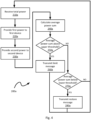
- method 200 may be performed with the apparatus 10. Indeed, the method 200 may be one way in which apparatus 10 may be operated. Furthermore, the following discussion of method 200 may lead to a further understanding of the apparatus 10 and its various components. It is to be emphasized, that method 200 need not be performed in the exact sequence as shown, and various blocks may be performed in parallel rather than in sequence, or in a different sequence altogether.
- the power supply 15 receives electrical power from an external power source.
- the power received is the total amount of power being supplied to the apparatus 10. It is to be appreciated that the exact amount of power received at the power supply 15 is generally not constant. Instead, the amount of power received at the power supply 15 is dependent on the electrical load of the first device 20, the second device 25, and the controller 30. Accordingly, the sum of the power demands from all the parts of the apparatus 10 determines the total power to be received from the external power source.
- the power supply 15 may be protected by a fuse or circuit breaker to protect the power supply 15 from drawing too much power from the external power source. Accordingly, if the electrical load requests power above an upper power threshold value, the power supply 15 may be disabled by tripping the fuse or circuit breaker to protect from damage.
- the power supply 15 provides a portion of the total power to the first device 20.
- the proportion of the total power forming of this first power is determined by the electrical load or demand of the first device 20 relative to the other devices that are being provided power by the power supply 15.
- the power drawn by the first device 20 is a portion of the total power drawn by the power supply 15 from the external power source. Since the power supply 15 does not operate above the upper power threshold value due to a safety mechanism in this example, the first device 20 is to draw an amount of power less than the upper power threshold value of the power supply 15.
- the controller 30 may be used to measure the amount of power drawn by the first device 20.
- the controller 30 takes multiple measurements to determine an average power draw of the first device 20 over a period of time. Since the power drawn by the first device 20 may fluctuate over time due to changes in the operational state of the first device 20, the power drawn may be averaged to avoid reduce the effects of temporary spikes or lows in power demand. Accordingly, periodic data points may be measured to determine an average power draw by the first device 20.
- the power supply 15 provides a portion of the total power to the second device 25.
- the proportion of the total power forming this second power is determined by the electrical load or demand of the second device 25 relative to the other devices that are being provided power by the power supply 15.
- the power drawn by the second device 25 is a portion of the total power drawn by the power supply 15 from the external power source. Since the power supply 15 does not operate above the upper power threshold value due to a safety mechanism in this example, the second device 25 is to draw an amount of power less than the upper power threshold value of the power supply 15. However, in some operating conditions, the sum of the power drawn at block 220 and the power drawn at block 230 may exceed the upper power threshold as discuss below.
- the second device 25 may be used to measure the amount of power drawn by the second device 25.
- the controller 30 takes multiple measurements to determine an average power draw of the second device 25 over a period of time. Since the power drawn by the second device 25 may fluctuate over time due to changes in the operational state of the second device 25, the power drawn may be averaged to reduce the effects of temporary spikes or lows in power demand. Accordingly, periodic data points may be measured to determine an average power draw by the second device 25.
- block 240 involves calculating the average power sum which is to approximate the total power drawn from the power supply 15.
- the average power sum is obtained by adding the average power drawn by the first device 20 and the second device 25.
- Block 250 comprises determining whether the average power sum calculated at block 240 is greater than the upper power threshold value of the power supply 15. In the event that the average power sum is above the upper power threshold value, the method 200 proceeds to block 260.
- the controller 30 is to transmit a limit message to the second device 25.
- the limit message is to direct the second device 25 to place a limit on the power consumption by its components.
- the manner by which the second device 25 limits its power may involve examining the processes running within and to determine which components are to have power limited. Accordingly, the second device 25 may determine the most effective way to achieve the power reduction with minimal impact to the processes that may be running instead of having power to the second device 25 reduced as a whole from the power supply 15.
- the controller 30 may further determine the amount that the average power sum is above the upper power threshold value.
- the limit message provided by the controller 30 may also include the amount the average power sum is above the upper power threshold value.
- the second device 25 may then be instructed to reduce the power consumption by this amount or a slightly larger amount to avoid triggering another limit message due to a minor power fluctuation.
- Block 270 comprises determining whether the average power sum calculated at block 240 is below the lower power threshold value. In the event that the average power sum is below the lower power threshold value, the method 200 proceeds to block 280.
- the controller 30 is to transmit a restore message to the second device 25.
- the restore message is to direct the second device 25 to remove or reduce a limit on the power consumption by its components. The manner by which the second device 25 removes the limits on its power may completely remove all limits. In another example, the limits on power consumption at the second device 25 may be incrementally relaxed until completely removed.
- the second device 25 may be under no limitations on the amount of power it may consume. Accordingly, if the method reaches block 280, then no action is to be taken by the second device 25 upon receiving the restore message. In the event that the average power sum is not below the lower power threshold value, the method 200 simply ends as no action is taken to manage the power supply 15.
- the apparatus 10a includes a power supply 15a, a first device 20a, a second device 25a, a controller 30a, and a memory storage unit 35a.
- the first device 20a includes the power supply 15a, the controller 30a, and the memory storage unit 35a. Accordingly, the first device 20a may be a display system capable of being plugged into a power source such as a wall outlet. The first device 20a may then have additional devices, such as the second device 25a, or other peripheral components connected thereto via a connector.
- the connector is not particularly limited an may be any connector capable of providing a data connection as well as providing power from the first device 20a to the additional devices, such as the second device 25a, or other peripheral components.
- the connector is a USB-C interface capable of providing power to the second device 25a from the power supply 15a in the first device 20a.
- the USB-C interface is also capable of transmitting messages, such as the limit messages and restore messages discussed above, in the form of power data objects, to the second device 25a.
- the apparatus 10a further includes a memory storage unit 35a within the first device 20a.
- the memory storage unit 35a is to store data received, generated, and used by the first device 20a.
- the manner by which the memory storage unit 35a stores the data is not particularly limited.
- the memory storage unit 35a may include a non-transitory machine-readable storage medium that may be, for example, an electronic, magnetic, optical, or other physical storage device.
- the memory storage unit 35a may store an operating system that is executable by the first device 20a to provide general functionality. Continuing with the present example of the first device 20a being a display system, the operating system may provide functionality to various components to render data.
- the memory storage unit 35a may additionally store instructions to operate a processor (not shown) within the first device 20a to carry out various functions described above as well as the method 200.
- a flowchart of another example method of operating an apparatus to manage power between a plurality of devices is generally shown at 200a.
- Like blocks of the method 200a bear like reference to their counterparts in the method 200, except followed by the suffix "a".
- method 200a may be performed with the apparatus 10a. Indeed, the method 200a may be another way in which apparatus 10a may be configured. Furthermore, the following discussion of method 200a may lead to a further understanding of the apparatus 10a and the various ways in which it may be configured. It is to be appreciated the method 200a may also be applied to the apparatus 10.
- the power supply 15a receives electrical power from an external power source.
- the power supply 15 has an upper operating limit and is protected by a fuse or circuit breaker to avoid having the power supply 15a drawing too much power from the external power source.
- the power supply 15a provides a first portion of the total power to the first device 20a.
- the first portion of the total power is to be distributed directly to the components of the first device 20a by the power supply 15a.
- the power supply 15a provides a second portion of the total power to the second device 25a. Since the second device 25a is separate from the first device 20a, the power is transmitted to the second device 25a via a connector, such as a USB-C interface.
- the controller 30a is to measure the amount of power drawn by the first device 20a and the second device 25a. In this example, the controller 30a takes multiple measurements to determine an average power draw of the first device 20a and the second device 25a over a period of time.
- block 240a involves calculating the average power sum which involves adding the power measured during the execution of blocks 220a and 230a.
- Block 250a comprises determining whether the average power sum calculated at block 240a is greater than an upper power threshold value of the power supply 15a.
- the upper power threshold may be set relative to the upper operating limit, such as 10W below the operating limit.
- the method 200a proceeds to block 260a to transmit a limit message to the second device 25a.
- the limit message is a command to direct the second device 25a to limit the power demand by its components.
- Block 270a comprises determining whether the average power sum calculated at block 240a is below the lower power threshold value. In the event that the average power sum is below the lower power threshold value, the method 200a proceeds to block 280a.
- the controller 30a is to transmit a restore message to the second device 25a.
- the restore message is a command to direct the second device 25a to reduce the limit on the power demand by its components, if a limit is present.
- the method 200a loops back to block 210a. It is to be appreciated that the method 200a is an iterative loop that continues to repeat. In some examples, a delay may be added so that the loop to be carried out less frequently to reduce demand on the resources of the controller 30a.
Landscapes
- Engineering & Computer Science (AREA)
- Theoretical Computer Science (AREA)
- General Engineering & Computer Science (AREA)
- Physics & Mathematics (AREA)
- General Physics & Mathematics (AREA)
- Computer Hardware Design (AREA)
- Computing Systems (AREA)
- Supply And Distribution Of Alternating Current (AREA)
Claims (14)
- Appareil (10) comprenant :une alimentation électrique (15) à connecter à une source d'alimentation, l'alimentation électrique servant à recevoir et à distribuer une puissance totale provenant de la source d'alimentation ;un premier dispositif (20) pour recevoir une première partie de la puissance totale provenant de l'alimentation électrique ;un second dispositif (25) pour recevoir une seconde partie de la puissance totale provenant de l'alimentation électrique, dans lequel la somme de la première partie et de la seconde partie est la puissance totale ; etun dispositif de commande (30) pour commander le second dispositif, dans lequel le dispositif de commande doit déterminer la puissance totale demandée par le premier dispositif et le second dispositif sur la base d'un calcul d'une puissance totale moyenne par l'intermédiaire d'une mesure de la puissance totale sur une période de temps, le dispositif de commande devant réduire la seconde partie de la puissance totale si la puissance totale est supérieure à une valeur seuil supérieure, et le dispositif de commande devant restaurer la seconde partie de la puissance totale si la puissance totale est inférieure à une valeur seuil inférieure.
- Appareil (10) selon la revendication 1, dans lequel le dispositif de commande doit déterminer la seconde partie de la puissance totale sur la période de temps.
- Appareil (10) selon la revendication 2, dans lequel le dispositif de commande détermine de quelle quantité la puissance totale dépasse la valeur seuil supérieure.
- Appareil (10) selon la revendication 3, dans lequel le dispositif de commande doit réduire la seconde partie de la quantité.
- Appareil (10) selon la revendication 4, dans lequel l'alimentation électrique et le dispositif de commande sont disposés au sein du premier dispositif.
- Appareil (10) selon la revendication 5, dans lequel le second dispositif doit se connecter au premier dispositif par l'intermédiaire d'une interface USB-C, dans lequel des messages du dispositif de commande et la seconde partie de la puissance totale doivent être transmis par l'intermédiaire de l'interface USB-C.
- Procédé (200) comprenant :la réception (210) d'une puissance totale au niveau d'une alimentation électrique à connecter à une source d'alimentation externe, dans lequel l'alimentation électrique a un seuil de puissance supérieur ;la fourniture (220) d'une première puissance à un premier dispositif, dans lequel une première moyenne de la première puissance sur une période de temps est inférieure au seuil de puissance supérieur ;la fourniture (230) d'une seconde puissance à un second dispositif, dans lequel une seconde moyenne de la seconde puissance sur la période de temps est inférieure au seuil de puissance supérieur ;le calcul (240) d'une somme de puissance moyenne de la première moyenne et de la seconde moyenne ;la transmission (260) d'un message de limite au second dispositif si la somme de puissance moyenne est supérieure au seuil de puissance supérieur, le message de limite servant à imposer une limite à une consommation d'énergie du second dispositif ; etla transmission (280) d'un message de restauration au second dispositif si la somme de puissance moyenne est inférieure à un seuil de puissance inférieur, le message de restauration servant à supprimer la limite de consommation d'énergie au niveau du second dispositif.
- Procédé (200) selon la revendication 7, comprenant en outre la détermination de quelle quantité la somme de puissance moyenne dépasse le seuil de puissance supérieur.
- Procédé (200) selon la revendication 8, dans lequel le message de limite sert à ordonner au second dispositif de réduire la consommation d'énergie de la quantité.
- Procédé (200) selon la revendication 9, dans lequel la transmission du message de limite envoie le message de limite par l'intermédiaire d'une interface USB-C.
- Procédé (200) selon la revendication 10, dans lequel la fourniture de la seconde puissance au second dispositif doit être effectuée par l'intermédiaire de l'interface USB-C.
- Support de stockage non transitoire lisible par machine codé avec des instructions exécutables par un processeur, le support de stockage non transitoire lisible par machine comprenant :des instructions pour calculer une première moyenne d'une première partie d'une puissance totale et une seconde moyenne d'une seconde partie de la puissance totale sur une période de temps, dans lequel la première partie de la puissance totale est reçue par un premier dispositif et la seconde partie de la puissance totale est reçue par un second dispositif, et dans lequel une alimentation électrique avec un seuil de puissance supérieur doit recevoir et distribuer la puissance totale au premier dispositif et au second dispositif ;des instructions pour calculer une somme de puissance moyenne de la première moyenne et de la seconde moyenne ;des instructions pour transmettre un message de limite au second dispositif si la somme de puissance moyenne est supérieure au seuil de puissance supérieur, dans lequel le message de limite est une première commande pour limiter une demande de puissance au niveau du second dispositif ; etdes instructions pour transmettre un message de restauration au second dispositif si la somme de puissance moyenne est inférieure à un seuil de puissance inférieur, dans lequel le message de restauration est une seconde commande pour supprimer la limite de demande de puissance au niveau du second dispositif.
- Support de stockage non transitoire lisible par machine selon la revendication 12, comprenant en outre des instructions pour déterminer de quelle quantité la somme de puissance moyenne dépasse le seuil de puissance supérieur.
- Support de stockage non transitoire lisible par machine selon la revendication 13, dans lequel le message de limite sert à ordonner au second dispositif de réduire la demande de puissance de la quantité.
Applications Claiming Priority (1)
| Application Number | Priority Date | Filing Date | Title |
|---|---|---|---|
| PCT/US2019/032979 WO2020236143A1 (fr) | 2019-05-17 | 2019-05-17 | Systèmes de gestion de puissance |
Publications (3)
| Publication Number | Publication Date |
|---|---|
| EP3969983A1 EP3969983A1 (fr) | 2022-03-23 |
| EP3969983A4 EP3969983A4 (fr) | 2023-01-18 |
| EP3969983B1 true EP3969983B1 (fr) | 2025-01-22 |
Family
ID=73458256
Family Applications (1)
| Application Number | Title | Priority Date | Filing Date |
|---|---|---|---|
| EP19929416.6A Active EP3969983B1 (fr) | 2019-05-17 | 2019-05-17 | Systèmes de gestion de puissance |
Country Status (5)
| Country | Link |
|---|---|
| US (1) | US11507177B2 (fr) |
| EP (1) | EP3969983B1 (fr) |
| CN (1) | CN113811839B (fr) |
| TW (1) | TW202043980A (fr) |
| WO (1) | WO2020236143A1 (fr) |
Family Cites Families (21)
| Publication number | Priority date | Publication date | Assignee | Title |
|---|---|---|---|---|
| US7474276B2 (en) | 2000-06-20 | 2009-01-06 | Olympus Optical Co., Ltd. | Display system and microdisplay apparatus |
| US20030107566A1 (en) | 2001-12-08 | 2003-06-12 | Samsung Electronics Co., Ltd. | Display apparatus and method of supplying power to USB device thereof |
| US7541776B2 (en) | 2004-12-10 | 2009-06-02 | Apple Inc. | Method and system for operating a portable electronic device in a power-limited manner |
| US8266456B2 (en) | 2007-10-15 | 2012-09-11 | Apple Inc. | Supplying remaining available current to port in excess of bus standard limit |
| JP2009151488A (ja) | 2007-12-19 | 2009-07-09 | Toshiba Corp | 情報処理装置 |
| KR20090113016A (ko) | 2008-04-25 | 2009-10-29 | 삼성전자주식회사 | 디스플레이 장치 및 이를 적용한 디스플레이 전원공급방법 |
| US7884499B2 (en) * | 2008-06-30 | 2011-02-08 | Intel Corporation | Intervention of independent self-regulation of power consumption devices |
| US20100023786A1 (en) | 2008-07-24 | 2010-01-28 | Liberman Izidor | System and method for reduction of electricity production and demand |
| EP2200142B1 (fr) * | 2008-12-19 | 2014-04-16 | ABB Oy | Procédé et agencement de la limitation du courant électrique nécessaire pour des charges électriques |
| US20120144215A1 (en) * | 2010-12-03 | 2012-06-07 | Advanced Micro Devices, Inc. | Maximum current limiting method and apparatus |
| KR101956527B1 (ko) | 2011-12-26 | 2019-06-24 | 삼성전자 주식회사 | Usb 호스트 장치 및 그 전원 관리 방법 |
| CN102573035B (zh) * | 2011-12-26 | 2015-04-29 | 华为技术有限公司 | 为终端设置功率的方法和基站 |
| JP5895246B2 (ja) * | 2012-04-26 | 2016-03-30 | パナソニックIpマネジメント株式会社 | 制御装置および制御方法 |
| JP5301008B1 (ja) | 2012-04-27 | 2013-09-25 | 株式会社東芝 | 電子機器、充電制御装置および充電制御方法 |
| US20150046726A1 (en) | 2013-08-12 | 2015-02-12 | Kabushiki Kaisha Toshiba | Electronic apparatus |
| TW201520752A (zh) * | 2013-11-29 | 2015-06-01 | Ibm | 電腦系統中的電源消耗控制 |
| CN104023346B (zh) * | 2014-06-27 | 2017-08-04 | 北京大学 | 移动通信基站接入用户的能效测量方法及资源调度方法 |
| US20180239718A1 (en) * | 2015-10-15 | 2018-08-23 | Hewlett-Packard Devlopment Company, L.P. | Utilizing Pins on a Universal Serial Bus (USB) Type-C Connector for a Data Signal |
| CN106089576B (zh) * | 2016-06-21 | 2018-10-30 | 湘电风能有限公司 | 一种实现风机控制中两套测风传感器自动切换的方法 |
| EP3430492A4 (fr) | 2016-07-12 | 2019-11-20 | Hewlett-Packard Development Company, L.P. | Équilibrage d'une charge d'électricité entre des ports usb |
| US20180314309A1 (en) * | 2017-04-27 | 2018-11-01 | Lenovo (Singapore) Pte. Ltd. | Smart usb power management |
-
2019
- 2019-05-17 EP EP19929416.6A patent/EP3969983B1/fr active Active
- 2019-05-17 US US17/419,043 patent/US11507177B2/en active Active
- 2019-05-17 WO PCT/US2019/032979 patent/WO2020236143A1/fr not_active Ceased
- 2019-05-17 CN CN201980096499.1A patent/CN113811839B/zh active Active
-
2020
- 2020-02-15 TW TW109104882A patent/TW202043980A/zh unknown
Also Published As
| Publication number | Publication date |
|---|---|
| EP3969983A1 (fr) | 2022-03-23 |
| US20220075441A1 (en) | 2022-03-10 |
| US11507177B2 (en) | 2022-11-22 |
| WO2020236143A1 (fr) | 2020-11-26 |
| CN113811839B (zh) | 2025-02-18 |
| CN113811839A (zh) | 2021-12-17 |
| TW202043980A (zh) | 2020-12-01 |
| EP3969983A4 (fr) | 2023-01-18 |
Similar Documents
| Publication | Publication Date | Title |
|---|---|---|
| CN114489305B (zh) | 功率管理和保护 | |
| US8880922B2 (en) | Computer and power management system for computer | |
| CN103097984B (zh) | 功率封顶系统 | |
| US20080155284A1 (en) | Power consumption adjusting apparatus and processing method | |
| US11068038B2 (en) | System and method for using current slew-rate telemetry in an information handling system | |
| CN103970248B (zh) | 电源管理电路与方法以及计算机系统 | |
| CN102395937A (zh) | 功率封顶系统及方法 | |
| EP2728440B1 (fr) | Dispositif et procédé de gestion de puissance électrique d'une pluralité d'interfaces périphériques | |
| CN106371540B (zh) | 系统电源管理方法、芯片及电子设备 | |
| EP3874341B1 (fr) | Procédé et appareil pour fournir une unité d'alimentation électrique à crête optimisée | |
| CN107122035A (zh) | 一种电源管理方法、装置及系统 | |
| WO2022245472A1 (fr) | Commande de puissance de crête dynamique | |
| US20130332751A1 (en) | Power supply and program | |
| CN115686935A (zh) | 数据备份方法、计算机设备及存储介质 | |
| US20200133361A1 (en) | Method and Apparatus to Provide Platform Power Peak Limiting based on Charge of Power Assist Unit | |
| US10983577B2 (en) | Method and apparatus to provide dynamic regulation of power assist unit output based on active profile | |
| US11507177B2 (en) | Power management systems | |
| CN113009996A (zh) | 待机状态风扇控制方法、装置、设备及机器可读存储介质 | |
| US11599182B2 (en) | Method and apparatus to distribute current indicator to multiple end-points | |
| CN120909412B (zh) | 服务器及其功耗管理方法、电子设备、介质及程序产品 | |
| CN111381659A (zh) | 计算机系统及电源管理方法 | |
| CN116382438A (zh) | 一种处理器过温保护方法、相关设备及可读存储介质 | |
| CN115292121A (zh) | 控制方法、装置及电子设备和存储介质 |
Legal Events
| Date | Code | Title | Description |
|---|---|---|---|
| STAA | Information on the status of an ep patent application or granted ep patent |
Free format text: STATUS: THE INTERNATIONAL PUBLICATION HAS BEEN MADE |
|
| PUAI | Public reference made under article 153(3) epc to a published international application that has entered the european phase |
Free format text: ORIGINAL CODE: 0009012 |
|
| STAA | Information on the status of an ep patent application or granted ep patent |
Free format text: STATUS: REQUEST FOR EXAMINATION WAS MADE |
|
| 17P | Request for examination filed |
Effective date: 20211116 |
|
| AK | Designated contracting states |
Kind code of ref document: A1 Designated state(s): AL AT BE BG CH CY CZ DE DK EE ES FI FR GB GR HR HU IE IS IT LI LT LU LV MC MK MT NL NO PL PT RO RS SE SI SK SM TR |
|
| DAV | Request for validation of the european patent (deleted) | ||
| DAX | Request for extension of the european patent (deleted) | ||
| REG | Reference to a national code |
Ref country code: DE Ref legal event code: R079 Free format text: PREVIOUS MAIN CLASS: G06F0001280000 Ipc: G06F0001320600 Ref country code: DE Ref legal event code: R079 Ref document number: 602019065280 Country of ref document: DE Free format text: PREVIOUS MAIN CLASS: G06F0001280000 Ipc: G06F0001320600 |
|
| A4 | Supplementary search report drawn up and despatched |
Effective date: 20221219 |
|
| RIC1 | Information provided on ipc code assigned before grant |
Ipc: G06F 1/28 20060101ALI20221213BHEP Ipc: G06F 1/26 20060101ALI20221213BHEP Ipc: G06F 1/3206 20190101AFI20221213BHEP |
|
| GRAP | Despatch of communication of intention to grant a patent |
Free format text: ORIGINAL CODE: EPIDOSNIGR1 |
|
| STAA | Information on the status of an ep patent application or granted ep patent |
Free format text: STATUS: GRANT OF PATENT IS INTENDED |
|
| INTG | Intention to grant announced |
Effective date: 20240820 |
|
| GRAS | Grant fee paid |
Free format text: ORIGINAL CODE: EPIDOSNIGR3 |
|
| GRAA | (expected) grant |
Free format text: ORIGINAL CODE: 0009210 |
|
| STAA | Information on the status of an ep patent application or granted ep patent |
Free format text: STATUS: THE PATENT HAS BEEN GRANTED |
|
| AK | Designated contracting states |
Kind code of ref document: B1 Designated state(s): AL AT BE BG CH CY CZ DE DK EE ES FI FR GB GR HR HU IE IS IT LI LT LU LV MC MK MT NL NO PL PT RO RS SE SI SK SM TR |
|
| REG | Reference to a national code |
Ref country code: GB Ref legal event code: FG4D |
|
| REG | Reference to a national code |
Ref country code: CH Ref legal event code: EP |
|
| REG | Reference to a national code |
Ref country code: IE Ref legal event code: FG4D |
|
| REG | Reference to a national code |
Ref country code: DE Ref legal event code: R096 Ref document number: 602019065280 Country of ref document: DE |
|
| REG | Reference to a national code |
Ref country code: NL Ref legal event code: MP Effective date: 20250122 |
|
| PG25 | Lapsed in a contracting state [announced via postgrant information from national office to epo] |
Ref country code: NL Free format text: LAPSE BECAUSE OF FAILURE TO SUBMIT A TRANSLATION OF THE DESCRIPTION OR TO PAY THE FEE WITHIN THE PRESCRIBED TIME-LIMIT Effective date: 20250122 |
|
| PG25 | Lapsed in a contracting state [announced via postgrant information from national office to epo] |
Ref country code: RS Free format text: LAPSE BECAUSE OF FAILURE TO SUBMIT A TRANSLATION OF THE DESCRIPTION OR TO PAY THE FEE WITHIN THE PRESCRIBED TIME-LIMIT Effective date: 20250422 |
|
| PG25 | Lapsed in a contracting state [announced via postgrant information from national office to epo] |
Ref country code: FI Free format text: LAPSE BECAUSE OF FAILURE TO SUBMIT A TRANSLATION OF THE DESCRIPTION OR TO PAY THE FEE WITHIN THE PRESCRIBED TIME-LIMIT Effective date: 20250122 |
|
| PG25 | Lapsed in a contracting state [announced via postgrant information from national office to epo] |
Ref country code: PL Free format text: LAPSE BECAUSE OF FAILURE TO SUBMIT A TRANSLATION OF THE DESCRIPTION OR TO PAY THE FEE WITHIN THE PRESCRIBED TIME-LIMIT Effective date: 20250122 |
|
| PGFP | Annual fee paid to national office [announced via postgrant information from national office to epo] |
Ref country code: DE Payment date: 20250423 Year of fee payment: 7 |
|
| PG25 | Lapsed in a contracting state [announced via postgrant information from national office to epo] |
Ref country code: ES Free format text: LAPSE BECAUSE OF FAILURE TO SUBMIT A TRANSLATION OF THE DESCRIPTION OR TO PAY THE FEE WITHIN THE PRESCRIBED TIME-LIMIT Effective date: 20250122 |
|
| REG | Reference to a national code |
Ref country code: LT Ref legal event code: MG9D |
|
| PG25 | Lapsed in a contracting state [announced via postgrant information from national office to epo] |
Ref country code: IS Free format text: LAPSE BECAUSE OF FAILURE TO SUBMIT A TRANSLATION OF THE DESCRIPTION OR TO PAY THE FEE WITHIN THE PRESCRIBED TIME-LIMIT Effective date: 20250522 Ref country code: NO Free format text: LAPSE BECAUSE OF FAILURE TO SUBMIT A TRANSLATION OF THE DESCRIPTION OR TO PAY THE FEE WITHIN THE PRESCRIBED TIME-LIMIT Effective date: 20250422 |
|
| REG | Reference to a national code |
Ref country code: AT Ref legal event code: MK05 Ref document number: 1761937 Country of ref document: AT Kind code of ref document: T Effective date: 20250122 |
|
| PG25 | Lapsed in a contracting state [announced via postgrant information from national office to epo] |
Ref country code: HR Free format text: LAPSE BECAUSE OF FAILURE TO SUBMIT A TRANSLATION OF THE DESCRIPTION OR TO PAY THE FEE WITHIN THE PRESCRIBED TIME-LIMIT Effective date: 20250122 |
|
| PG25 | Lapsed in a contracting state [announced via postgrant information from national office to epo] |
Ref country code: PT Free format text: LAPSE BECAUSE OF FAILURE TO SUBMIT A TRANSLATION OF THE DESCRIPTION OR TO PAY THE FEE WITHIN THE PRESCRIBED TIME-LIMIT Effective date: 20250522 Ref country code: LV Free format text: LAPSE BECAUSE OF FAILURE TO SUBMIT A TRANSLATION OF THE DESCRIPTION OR TO PAY THE FEE WITHIN THE PRESCRIBED TIME-LIMIT Effective date: 20250122 |
|
| PG25 | Lapsed in a contracting state [announced via postgrant information from national office to epo] |
Ref country code: GR Free format text: LAPSE BECAUSE OF FAILURE TO SUBMIT A TRANSLATION OF THE DESCRIPTION OR TO PAY THE FEE WITHIN THE PRESCRIBED TIME-LIMIT Effective date: 20250423 Ref country code: BG Free format text: LAPSE BECAUSE OF FAILURE TO SUBMIT A TRANSLATION OF THE DESCRIPTION OR TO PAY THE FEE WITHIN THE PRESCRIBED TIME-LIMIT Effective date: 20250122 |
|
| PG25 | Lapsed in a contracting state [announced via postgrant information from national office to epo] |
Ref country code: AT Free format text: LAPSE BECAUSE OF FAILURE TO SUBMIT A TRANSLATION OF THE DESCRIPTION OR TO PAY THE FEE WITHIN THE PRESCRIBED TIME-LIMIT Effective date: 20250122 |
|
| PG25 | Lapsed in a contracting state [announced via postgrant information from national office to epo] |
Ref country code: SE Free format text: LAPSE BECAUSE OF FAILURE TO SUBMIT A TRANSLATION OF THE DESCRIPTION OR TO PAY THE FEE WITHIN THE PRESCRIBED TIME-LIMIT Effective date: 20250122 |
|
| PG25 | Lapsed in a contracting state [announced via postgrant information from national office to epo] |
Ref country code: SM Free format text: LAPSE BECAUSE OF FAILURE TO SUBMIT A TRANSLATION OF THE DESCRIPTION OR TO PAY THE FEE WITHIN THE PRESCRIBED TIME-LIMIT Effective date: 20250122 |
|
| PG25 | Lapsed in a contracting state [announced via postgrant information from national office to epo] |
Ref country code: DK Free format text: LAPSE BECAUSE OF FAILURE TO SUBMIT A TRANSLATION OF THE DESCRIPTION OR TO PAY THE FEE WITHIN THE PRESCRIBED TIME-LIMIT Effective date: 20250122 |
|
| PG25 | Lapsed in a contracting state [announced via postgrant information from national office to epo] |
Ref country code: IT Free format text: LAPSE BECAUSE OF FAILURE TO SUBMIT A TRANSLATION OF THE DESCRIPTION OR TO PAY THE FEE WITHIN THE PRESCRIBED TIME-LIMIT Effective date: 20250122 |
|
| PG25 | Lapsed in a contracting state [announced via postgrant information from national office to epo] |
Ref country code: EE Free format text: LAPSE BECAUSE OF FAILURE TO SUBMIT A TRANSLATION OF THE DESCRIPTION OR TO PAY THE FEE WITHIN THE PRESCRIBED TIME-LIMIT Effective date: 20250122 Ref country code: CZ Free format text: LAPSE BECAUSE OF FAILURE TO SUBMIT A TRANSLATION OF THE DESCRIPTION OR TO PAY THE FEE WITHIN THE PRESCRIBED TIME-LIMIT Effective date: 20250122 |
|
| REG | Reference to a national code |
Ref country code: DE Ref legal event code: R097 Ref document number: 602019065280 Country of ref document: DE |
|
| PG25 | Lapsed in a contracting state [announced via postgrant information from national office to epo] |
Ref country code: RO Free format text: LAPSE BECAUSE OF FAILURE TO SUBMIT A TRANSLATION OF THE DESCRIPTION OR TO PAY THE FEE WITHIN THE PRESCRIBED TIME-LIMIT Effective date: 20250122 |
|
| PG25 | Lapsed in a contracting state [announced via postgrant information from national office to epo] |
Ref country code: SK Free format text: LAPSE BECAUSE OF FAILURE TO SUBMIT A TRANSLATION OF THE DESCRIPTION OR TO PAY THE FEE WITHIN THE PRESCRIBED TIME-LIMIT Effective date: 20250122 |
|
| PLBE | No opposition filed within time limit |
Free format text: ORIGINAL CODE: 0009261 |
|
| STAA | Information on the status of an ep patent application or granted ep patent |
Free format text: STATUS: NO OPPOSITION FILED WITHIN TIME LIMIT |
|
| REG | Reference to a national code |
Ref country code: CH Ref legal event code: L10 Free format text: ST27 STATUS EVENT CODE: U-0-0-L10-L00 (AS PROVIDED BY THE NATIONAL OFFICE) Effective date: 20251203 |
|
| REG | Reference to a national code |
Ref country code: CH Ref legal event code: H13 Free format text: ST27 STATUS EVENT CODE: U-0-0-H10-H13 (AS PROVIDED BY THE NATIONAL OFFICE) Effective date: 20251223 |
|
| 26N | No opposition filed |
Effective date: 20251023 |
|
| PG25 | Lapsed in a contracting state [announced via postgrant information from national office to epo] |
Ref country code: LU Free format text: LAPSE BECAUSE OF NON-PAYMENT OF DUE FEES Effective date: 20250517 |
|
| PG25 | Lapsed in a contracting state [announced via postgrant information from national office to epo] |
Ref country code: CH Free format text: LAPSE BECAUSE OF NON-PAYMENT OF DUE FEES Effective date: 20250531 |
|
| GBPC | Gb: european patent ceased through non-payment of renewal fee |
Effective date: 20250517 |
|
| REG | Reference to a national code |
Ref country code: BE Ref legal event code: MM Effective date: 20250531 |
|
| PG25 | Lapsed in a contracting state [announced via postgrant information from national office to epo] |
Ref country code: MC Free format text: LAPSE BECAUSE OF FAILURE TO SUBMIT A TRANSLATION OF THE DESCRIPTION OR TO PAY THE FEE WITHIN THE PRESCRIBED TIME-LIMIT Effective date: 20250122 |
|
| PG25 | Lapsed in a contracting state [announced via postgrant information from national office to epo] |
Ref country code: GB Free format text: LAPSE BECAUSE OF NON-PAYMENT OF DUE FEES Effective date: 20250517 |
|
| PG25 | Lapsed in a contracting state [announced via postgrant information from national office to epo] |
Ref country code: IE Free format text: LAPSE BECAUSE OF NON-PAYMENT OF DUE FEES Effective date: 20250517 |
|
| PG25 | Lapsed in a contracting state [announced via postgrant information from national office to epo] |
Ref country code: BE Free format text: LAPSE BECAUSE OF NON-PAYMENT OF DUE FEES Effective date: 20250531 |
|
| PG25 | Lapsed in a contracting state [announced via postgrant information from national office to epo] |
Ref country code: FR Free format text: LAPSE BECAUSE OF NON-PAYMENT OF DUE FEES Effective date: 20250531 |