EP3969971B1 - Contrôle d'opérations manuelles par l'intermédiaire d'un outil à main portatif lors d'une fabrication d'un assemblage de pièces - Google Patents
Contrôle d'opérations manuelles par l'intermédiaire d'un outil à main portatif lors d'une fabrication d'un assemblage de pièces Download PDFInfo
- Publication number
- EP3969971B1 EP3969971B1 EP20754309.1A EP20754309A EP3969971B1 EP 3969971 B1 EP3969971 B1 EP 3969971B1 EP 20754309 A EP20754309 A EP 20754309A EP 3969971 B1 EP3969971 B1 EP 3969971B1
- Authority
- EP
- European Patent Office
- Prior art keywords
- assembly
- hand tool
- electronic module
- portable
- parts
- Prior art date
- Legal status (The legal status is an assumption and is not a legal conclusion. Google has not performed a legal analysis and makes no representation as to the accuracy of the status listed.)
- Active
Links
Images

Classifications
-
- G—PHYSICS
- G05—CONTROLLING; REGULATING
- G05B—CONTROL OR REGULATING SYSTEMS IN GENERAL; FUNCTIONAL ELEMENTS OF SUCH SYSTEMS; MONITORING OR TESTING ARRANGEMENTS FOR SUCH SYSTEMS OR ELEMENTS
- G05B19/00—Program-control systems
- G05B19/02—Program-control systems electric
- G05B19/418—Total factory control, i.e. centrally controlling a plurality of machines, e.g. direct or distributed numerical control [DNC], flexible manufacturing systems [FMS], integrated manufacturing systems [IMS] or computer integrated manufacturing [CIM]
- G05B19/41805—Total factory control, i.e. centrally controlling a plurality of machines, e.g. direct or distributed numerical control [DNC], flexible manufacturing systems [FMS], integrated manufacturing systems [IMS] or computer integrated manufacturing [CIM] characterised by assembly
-
- B—PERFORMING OPERATIONS; TRANSPORTING
- B25—HAND TOOLS; PORTABLE POWER-DRIVEN TOOLS; MANIPULATORS
- B25F—COMBINATION OR MULTI-PURPOSE TOOLS NOT OTHERWISE PROVIDED FOR; DETAILS OR COMPONENTS OF PORTABLE POWER-DRIVEN TOOLS NOT PARTICULARLY RELATED TO THE OPERATIONS PERFORMED AND NOT OTHERWISE PROVIDED FOR
- B25F5/00—Details or components of portable power-driven tools not particularly related to the operations performed and not otherwise provided for
- B25F5/02—Construction of casings, bodies or handles
-
- G—PHYSICS
- G06—COMPUTING OR CALCULATING; COUNTING
- G06F—ELECTRIC DIGITAL DATA PROCESSING
- G06F30/00—Computer-aided design [CAD]
- G06F30/10—Geometric CAD
- G06F30/12—Geometric CAD characterised by design entry means specially adapted for CAD, e.g. graphical user interfaces [GUI] specially adapted for CAD
-
- G—PHYSICS
- G06—COMPUTING OR CALCULATING; COUNTING
- G06F—ELECTRIC DIGITAL DATA PROCESSING
- G06F30/00—Computer-aided design [CAD]
- G06F30/10—Geometric CAD
- G06F30/17—Mechanical parametric or variational design
-
- G—PHYSICS
- G06—COMPUTING OR CALCULATING; COUNTING
- G06T—IMAGE DATA PROCESSING OR GENERATION, IN GENERAL
- G06T17/00—Three-dimensional [3D] modelling for computer graphics
-
- G—PHYSICS
- G05—CONTROLLING; REGULATING
- G05B—CONTROL OR REGULATING SYSTEMS IN GENERAL; FUNCTIONAL ELEMENTS OF SUCH SYSTEMS; MONITORING OR TESTING ARRANGEMENTS FOR SUCH SYSTEMS OR ELEMENTS
- G05B2219/00—Program-control systems
- G05B2219/30—Nc systems
- G05B2219/31—From computer integrated manufacturing till monitoring
- G05B2219/31027—Computer assisted manual assembly CAA, display operation, tool, result
-
- G—PHYSICS
- G05—CONTROLLING; REGULATING
- G05B—CONTROL OR REGULATING SYSTEMS IN GENERAL; FUNCTIONAL ELEMENTS OF SUCH SYSTEMS; MONITORING OR TESTING ARRANGEMENTS FOR SUCH SYSTEMS OR ELEMENTS
- G05B2219/00—Program-control systems
- G05B2219/30—Nc systems
- G05B2219/31—From computer integrated manufacturing till monitoring
- G05B2219/31046—Aid for assembly, show display on screen next workpiece, task, position to be assembled, executed
-
- G—PHYSICS
- G05—CONTROLLING; REGULATING
- G05B—CONTROL OR REGULATING SYSTEMS IN GENERAL; FUNCTIONAL ELEMENTS OF SUCH SYSTEMS; MONITORING OR TESTING ARRANGEMENTS FOR SUCH SYSTEMS OR ELEMENTS
- G05B2219/00—Program-control systems
- G05B2219/30—Nc systems
- G05B2219/45—Nc applications
- G05B2219/45055—Assembly
-
- G—PHYSICS
- G05—CONTROLLING; REGULATING
- G05B—CONTROL OR REGULATING SYSTEMS IN GENERAL; FUNCTIONAL ELEMENTS OF SUCH SYSTEMS; MONITORING OR TESTING ARRANGEMENTS FOR SUCH SYSTEMS OR ELEMENTS
- G05B2219/00—Program-control systems
- G05B2219/30—Nc systems
- G05B2219/45—Nc applications
- G05B2219/45127—Portable, hand drill
Definitions
- the present invention generally relates to manufacturing and/or maintenance operations of an assembly of parts using a portable hand tool to enable an assembly technician to perform manual operations on elements of the assembly.
- the portable hand tool may be a tightening tool (wrench or screwdriver) suitable for performing tightening operations on tightening elements such as screws and nuts forming bolts.
- the portable hand tool may also be a tool suitable for installing elements such as rivets, or a tool suitable for performing drilling, welding or cutting at different locations in the assembly of parts.
- Controlling manual operations performed by an assembly technician using a hand tool when assembling parts is essential in many sectors of industry, for example related to transportation, particularly the aerospace industry where assembly processes can be very complex.
- the position of the tightening tool in a three-dimensional coordinate system linked to the manufacturing space, and therefore of the tightening element tightened by the tightening tool is conventionally obtained from the radiofrequency signals emitted at the tightening tool and received by the radiofrequency beacons, for example with time-of-flight and trilateration techniques.
- the radio frequency signals emitted at the clamping tool may further include information relating to the status of each clamping operation, such as an indication that the clamping operation has started, is in progress and/or is completed.
- the different positions occupied by the clamping tool determined by the location means are transmitted via a communication network (WAN, LAN or internet) to a reporting and display system comprising in particular screens of portable equipment (telephones, tablets) and fixed computer screens.
- the reporting and display system converts each position it receives in the three-dimensional coordinate system linked to the manufacturing space into a position in a three-dimensional coordinate system associated with a set of modeling data, for example a CAD file, representing a three-dimensional modeled image of the assembly of parts.
- the reporting and display system can then control the display, on the various screens, of images which highlight in real time the location of each tightening element on the image. three-dimensional modeled, and the status of the tightening operation associated with each tightening element.
- the system described in the document US 8,311,658 This allows the status of the various tightening operations to be located, monitored and recorded remotely.
- the technician in charge of the tightening operations can also monitor the progress of the tightening operations.
- the present invention proposes a low-cost solution for locating and identifying very precisely the manual operations carried out on elements of a part assembly by means of a hand tool.
- the present invention relates to a manual operations control system according to claim 1.
- the present invention also relates to a method for controlling manual operations according to claim 14.
- the present invention will be described in the non-limiting context of the control of manual operations of the tightening type by means of a portable hand tool such as a screwdriver or a wrench, referred to hereinafter as a "portable tightening tool".
- a portable hand tool such as a screwdriver or a wrench
- the portable hand tool may also be a tool suitable for installing elements such as rivets or staples, or a tool suitable for drilling holes at different locations in the assembly, for welding different parts of the assembly or cutting parts of the assembly.
- the invention applies to other types of clamping tools adapted to other types of clamping elements, for example to screwdrivers for tightening screws, or, as indicated above, to other types of hand tools allowing other types of manual operations, for example a stapler, nailer, riveter, drill, welder or even cutter.
- the hand tool can be any pre-existing hand tool (for example a conventional or torque manual tightening wrench) on which the electronic module is subsequently fixed.
- the portable hand tool is designed to integrate the electronic module from the outset.
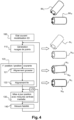
- FIG 1 schematically illustrates, by way of non-limiting example, a portable tightening tool, here a tightening key 1 for nuts, belonging to a system for controlling manual operations of a given type, here tightening, during the manufacture of an assembly of parts, in accordance with a first possible embodiment of the invention.
- reference 2 represents an example of a part that an assembly technician must assemble in an assembly (not shown) of parts, as well as two nuts 20, 21 that the technician must tighten by means of the portable tightening tool 1 to carry out the assembly of this part.
- the portable tightening tool 1 comprises an electronic module 3 which integrates, in this first embodiment, all the functionalities allowing the technician to control in real time the tightening operations that he performs.
- the electronic module 3 here comprises all of the location means capable of locating the position of the tightening key 1.
- These location means comprise firstly a depth camera 30 which captures three-dimensional images of the environment of the tightening key when the technician assembly moves this key to successively carry out the various tightening operations during the manufacture of the assembly.
- the depth camera 30 may be a stereoscopic type camera, or a camera operating on the time-of-flight principle (or TOF camera, an Anglo-Saxon initials for Time Of Flight), or a so-called structured light camera.
- the means for locating the electronic module 3 may further comprise an inertial unit 31 capable of delivering measurements of linear accelerations along three orthogonal axes linked to the electronic module (and therefore to the tightening key), and of angular velocities.
- the localization means further comprise a processing module 32 which receives the three-dimensional images captured by the depth camera 30, and, where appropriate, the measurements made by the inertial unit 31.
- the processing module 32 comprises a calculation algorithm for estimating the position of the electronic module 3, and consequently, of the tightening key 1, from at least the three-dimensional images captured by the depth camera 30.
- the position is estimated in a three-dimensional frame linked to a 3D modeling of the assembly, this 3D modeling being obtained by three-dimensional modeling data contained in CAD files stored in a storage memory 33a, as will be explained later.
- a database 33b of the electronic module 3 makes it possible to record data relating to the tightening operations, in particular the identifiers of the tightening elements on which the technician intervenes during the assembly process.
- the electronic module 3 also comprises, in this example, different user interfaces, in particular a display screen 34.
- the user interfaces may further comprise one or more manual control buttons 35, and one or more visual indicators 36, such as light-emitting diodes.
- the electronic module 3 also comprises one or more communication modules 37 allowing it to exchange information with external equipment such as a portable tablet, a PC or a server. If the hand tool is a connected tool (for example a smart torque wrench), a communication module 38 is provided. communication can be provided to allow the electronic module 3 to exchange data with this connected tool. Any wired (Ethernet%) or wireless (Wifi, Bluetooth%) communication protocol can be used.
- the figure 2 finally shows a microprocessor 38a and its associated memory 38b, making it possible to control the operation of the various components of the electronic module 3, as well as a power supply battery 39.
- the system of Figures 1 and 2 can be used as follows: The assembly technician takes the tightening wrench 1 and moves it until it is opposite one of the bolts he has to tighten, for example bolt 20 as shown in the figure. figure 1 . From the images captured by the depth camera 30, the electronic module 3 will be able to calculate and store its position relative to the three-dimensional modeling of the assembly. More precisely, as will be explained in more detail later, a current position of the electronic module 3 can be estimated by aligning point clouds extracted from at least one current 3D image delivered by the depth camera 30 with point clouds extracted from a three-dimensional image modeling a current state of the assembly of parts (for example CAD files), which the processing module 32 obtains in the storage memory 33a.
- the point clouds extracted from an image delivered by the depth camera 30 can be aligned directly on a three-dimensional mesh (“mesh” in English terminology) modeling a current state of the assembly of parts.
- the three-dimensional meshes can correspond directly to the CAD files modeling the assembly.
- the electronic module 3 is likely to know at any time, or at least regularly, its relative position with respect to the current state of the modeled assembly.
- the estimation made from 3D images makes it possible to obtain an accuracy in the estimated position of less than a millimeter.
- the tightening tool 1 faces a bolt on which the assembly technician is preparing to intervene, the system makes it possible to locate and thus identify this bolt very precisely.
- the processing module 32 can advantageously be configured to estimate a movement of the tightening tool 1 from a last position current position that it has estimated and stored from images captured by the depth camera 30, and update the position of the clamping tool 1 according to this movement and this last estimated current position.
- the setpoint parameters for each manual operation that the technician must perform may advantageously have been stored in advance, for example in the CAD files modeling the assembly stored in the storage module 33a of the electronic module 3.
- the parameters are tightening setpoints to be applied for each clamping element.
- the setpoint parameters relate to a force to be applied.
- the setpoint parameters include, for example, the diameter and/or rotation speed of the drill.
- the setpoint parameters include, for example, the diameter and speed of the wire, the intensity and/or the pulse frequency of the welding arc.
- this electronic module 3 can retrieve from the storage module 33a the instruction, here tightening (typically a tightening torque) adapted to the tightening element on which the assembly technician is working, on the basis of the estimated position, and automatically control the display of this tightening instruction on the screen 34 of the electronic module 3.
- tightening typically a tightening torque
- an audible indicator making it possible to indicate to the assembly technician by an audible signal the tightening instruction parameter that he must apply to a tightening element, depending on the location of the tightening operation associated with this tightening element, or a remote display screen on a remote device, for example a portable tablet (not shown in the figure).
- figure 1 with which the electronic module 3 can exchange information via a wireless communication module using for example the Wifi or Bluetooth protocol.
- the visual indicator 36 for example a diode, can emit a light of a predetermined color, for example green, so as to indicate to the assembly technician that he is indeed working on the correct tightening element.
- the technician can validate the tightening operation by means, for example, of a manually controlled button 35. The actuation of this button then triggers the automatic storage, preferably in the database 33b, of information relating to the tightening operation that the assembly technician has just carried out.
- This information advantageously includes a precise time stamp of the end of the tightening operation, corresponding for example to the moment at which the assembly technician validated the tightening operation by the button 35 (the moment the button was triggered), as well as a reference making it possible to uniquely identify the tightening element associated with the tightening operation.
- the validation of a tightening operation and the storage of information relating to the tightening operation may be automatic in certain embodiments: For example, in the case where the hand tool is a mechanical torque wrench, the measurements made by the inertial unit 31, when it is present, may be used to identify a sudden acceleration of the wrench around the bolt, corresponding to the clicking of the wrench when the tightening torque is reached.
- the hand tool is a connected torque wrench, i.e. capable in particular of transmitting information
- the wrench transmits to the electronic module 3, via the communication module 37 configured with the communication protocol adapted to that used by the wrench, the indication that the tightening torque entered as a setpoint has been reached, which corresponds to a validation of the operation.
- the measurements made by the inertial unit 31 can be used to estimate the tightening torque actually applied.
- the portable tightening tool 1 is a smart or connected wrench capable of measuring the tightening torque that has actually been applied, it is possible provide that the electronic module 3 also recovers and stores the tightening torque as measured by the wrench.
- Pressing button 35 can also trigger the automatic display on screen 34 of the next tightening operation to be carried out by the assembly technician, for example tightening bolt 21 on the figure 1 .
- the assembly technician repeats all of the operations described above for each of the tightening operations that he must perform on his assembly. At the end of these operations, the assembly technician may be invited, for example via a specific message displayed on the screen 34, to take a photograph of the assembly produced.
- the manual control button 35 may serve as a trigger to take the photograph via the camera 30.
- the photograph is advantageously stored, for example in the database 33b. It is thus possible to have visual proof of the quality of the assembly process.
- the assembly technician has a completely autonomous hand tool for controlling, checking and monitoring manual operations on the assembly of parts.
- FIG. 3 illustrates another embodiment of a tightening operation control system in accordance with the present invention.
- This system is similar to the system previously described with reference to Figures 1 and 2 in that it comprises an electronic module 3 fixed to the portable clamping tool 1, this module comprising at least the depth camera 30, and preferably also the inertial unit 31.
- the actual processing of the 3D images captured by the depth camera and, where appropriate, the measurements of the inertial unit is not here carried out locally at the level of the electronic module 3, but at the level of a remote equipment 4.
- This remote equipment is preferably a portable tablet intended to be used by the assembly technician.
- the processing module 32, the storage module 33a and the database 33b which had been described above with reference to the figure 2 are no longer integrated here into the electronic module 3, but at the level of the remote equipment 4 (integration not shown on the figure 3 ).
- All data necessary for the estimation of the tool position relative to a modeling of the assembly are transmitted by the communication module 37 of the electronic module 3 to a corresponding communication module (not shown) of the portable tablet 4 via a communication link 5, for example wireless of the Wifi or Bluetooth type.
- the assembly technician thus has the screen 40 of the remote equipment which is larger than the screen 34 of the module 3 of the figure 3 , which facilitates the control and monitoring operations.
- the current position of the tightening tool as estimated by the processing module can for example be displayed on the screen 40 superimposed on the three-dimensional modeled image of the assembly.
- a tightening instruction adapted to the tightening element on which the assembly technician is about to work can advantageously be retrieved from the CAD modeling files contained in the database, on the basis of the estimated location of the tightening tool making it possible to identify the tightening element, and notified to the assembly technician by display on the screen 40.
- the tightening operation is validated, either manually by the technician using the manually controlled button 35, or automatically. In all cases, validation triggers the automatic storage, in the database of the electronic module 3 and/or in the database remoted on the remote equipment, of information relating to the tightening operation that the assembly technician has just carried out.
- a control system therefore allows the assembly technician to be able to check in real time that he has correctly tightened all the clamping elements, and in the variant for which the appropriate tightening instructions are also automatically provided to the technician, to guarantee that each clamping element has been tightened with the correct tightening parameter.
- Table 1 gives an example of representation of the status of a tightening operation relating to a given tightening element. [Table 1] Hour Clamping element reference Tightening torque Status of the clamping action 11:57 11532 120 Nm OK
- the assembly technician or any other person can verify that the tightening element with the reference 11532 was tightened at 11:57 (corresponding to the moment of validation of the tightening operation), with a target or estimated tightening torque equal to 120 N.m.
- Other information can be added, such as the date of the tightening action, an identifier uniquely associated with an assembly technician.
- the mobile object that one wishes to locate may be the portable hand tool 1 described above in the non-limiting context of the control of manual tightening operations, in which case the location method may be implemented by a calculation algorithm of the processing module 32 of the electronic module 3, or of a processing module remoted on a remote equipment 4. More generally, the object that one wishes to locate may be any object capable of moving or being moved within an environment, for example the end of a robotic arm.
- the environment in which the mobile object will be located corresponds to the manufacturing space of an assembly of parts.
- CAD files In the context of the application to the control of manual operations such as tightening, CAD files must allow the assembly of parts to be modeled at different stages of the assembly process. In other words, modeling data is available to construct different digital models representative of the assembly at different stages of manufacturing of this assembly.
- the objective of the algorithm described below is to identify the relative position of the electronic module integrating the depth camera and the inertial unit, in a three-dimensional frame associated with the digital model corresponding to a current state of the assembly of parts.
- Step 100 in Figure 4 Determination of the digital model corresponding to the current modeled state of the assembly (Step 100 in Figure 4) :
- the assembly can be in several states depending on which parts have been assembled or not.
- the algorithm needs to know the current state of the digital model because it compares what is observed by the depth camera with what is observed digitally, i.e. with a three-dimensional modeled image representative of the current state of the assembly of parts.
- the current digital model can be directly filled in by a third party (operator, production monitoring software) who selects from the CAD files the one that represents the current state of the digital model.
- the current digital model is determined from a selection of points of interest extracted from a current three-dimensional image provided by the depth camera, to which are associated local parameters calculated according to the techniques traditionally used in 2D/3D object recognition.
- the calculated local parameters are compared with parameters obtained in the same way by numerically simulating what the camera sees from the 3D models at the different stages of the assembly.
- FIG. 4 On the right side of the figure 4 , an example of a current three-dimensional image Im C of a real assembly, captured by the camera of depth, and the modeled three-dimensional image Im M corresponding to the current modeled state of the assembly.
- the assembly considered corresponds to part 2 and nuts 20, 21 of the Figures 1 and 3 .
- the right part of the figure 4 illustrates a “source” point cloud N C extracted from the current three-dimensional image Im C and a “target” point cloud N M extracted from the modeled three-dimensional image Im M .
- step 110 will preferably use several images captured successively by the depth camera during a given period, each captured image being converted into a point cloud.
- the capture times of these successive images are preferably close enough together (corresponding for example to a capture frequency of 30 images per second) so that the different shots are similar.
- the point clouds obtained by these successive shots are then aligned so as to form only one “source” point cloud.
- step 110 will calculate the relative displacement between each shot from the measurements delivered by the inertial unit. By proceeding in this way, a very high density of points is advantageously obtained while reducing the digital noise potentially created by the depth camera.
- the process of aligning the "source” point cloud with the "target” point cloud is preferably carried out in two stages, first carrying out a rough alignment (sub-step 121), then a refinement of the alignment (sub-step 122).
- the sub-step 121 comprises for example a random selection of a plurality of points in the “source” point cloud. Each selected point is paired with the point of the “target” point cloud which has local parameters closest to those associated with the selected point, and an attempt is made to optimize the transformation which minimizes the distances between the points of the same pair.
- the right part of the figure 4 with regard to substep 121 illustrates the result of a rough alignment of the “source” point cloud N C extracted from the current three-dimensional image Im C and the “target” point cloud N M extracted from the modeled three-dimensional image Im M .
- sub-step 122 implements an ICP type algorithm (Iterative Closest Point), which consists of associating each point of the “source” point cloud with the closest point, in terms of Euclidean distance, of the “target” point cloud, then iteratively searching for the transformations necessary to minimize the distance between each paired point. At each iteration of the optimization, the points are re-associated.
- ICP type algorithm Iterative Closest Point
- the electronic module knows the transformation necessary to obtain the alignment of the points of the clouds, and consequently, deduces its position in the three-dimensional reference frame linked to the modeled image.
- the point clouds extracted from an image delivered by the depth camera 30 can be aligned not on point clouds modeling the assembly, but directly on a three-dimensional mesh (“mesh” in English terminology) modeling a current state of the assembly of parts.
- the calculation algorithm will advantageously update the position by calculating, during step 130, the displacement of the module relative to the position previously recorded from measurements delivered by said inertial unit.
- the position can thus be updated, for example by conventionally using Kalman filtering.
- a new three-dimensional image is captured by the depth camera.
- This image can be advantageously transformed into a point cloud and aligned with the "target" point cloud from the previously calculated displacement, then added to the "source” point cloud.
- the algorithm can advantageously filter the "source” cloud by randomly removing points when an area is too dense. A more intelligent selection of surplus points can also be considered by removing points that are not very coherent and/or by replacing small dense sets of points by their barycenters.
- Step 130 may be repeated a number of times, for example a predetermined number N of times, as shown in the figure 4 .
- N a predetermined number
- the calculation of the displacement loses a lot of precision over time, particularly because the acceleration measurements are integrated twice to calculate the displacement.
- the calculation algorithm can advantageously carry out a realignment of all the point clouds acquired by the depth camera during step 130, on the “target” point cloud, using for example an ICP type algorithm.
- the update of the estimation of the position of the electronic module by using the measurements delivered by the inertial unit can be carried out as long as that the estimated position is considered reliable. It is therefore desirable to periodically check the reliability of the estimate.
- the calculation algorithm can advantageously be configured, during a step 140, to align a point cloud extracted from an image captured by the camera with the “source” point cloud from its position as estimated.
- the reliability of the position is then defined as the sum of the Euclidean distances of each point of the “source” cloud relative to the “target” cloud. If the reliability goes above a certain predefined threshold, the estimation of the position by using the measurements of the inertial unit must be considered unreliable.
- the calculation algorithm is then configured to restart the steps from step 110.
- Combining the measurements of the inertial unit with the processing of the images captured by the depth camera can have many advantages, in addition to the gain in terms of computational costs.
- the depth camera may not provide sufficiently clear images for objects located too close.
- the measurements delivered by the inertial unit thus make it possible to fill the periods during which the camera could be insufficient, by making it possible to estimate a position of the portable tightening tool even when the latter is very close to the tightening element.
- the gain in accuracy can be further improved by combining the acceleration measurements for an update of the estimated position, for example by Kalman filtering.
Landscapes
- Engineering & Computer Science (AREA)
- Physics & Mathematics (AREA)
- Geometry (AREA)
- General Physics & Mathematics (AREA)
- Theoretical Computer Science (AREA)
- General Engineering & Computer Science (AREA)
- Mathematical Analysis (AREA)
- Mathematical Optimization (AREA)
- Pure & Applied Mathematics (AREA)
- Computer Hardware Design (AREA)
- Evolutionary Computation (AREA)
- Computational Mathematics (AREA)
- Architecture (AREA)
- Mechanical Engineering (AREA)
- Human Computer Interaction (AREA)
- Computer Graphics (AREA)
- Software Systems (AREA)
- Manufacturing & Machinery (AREA)
- Quality & Reliability (AREA)
- Automation & Control Theory (AREA)
- General Factory Administration (AREA)
- Length Measuring Devices By Optical Means (AREA)
- Image Processing (AREA)
- Automatic Assembly (AREA)
- Manipulator (AREA)
Applications Claiming Priority (2)
| Application Number | Priority Date | Filing Date | Title |
|---|---|---|---|
| FR1904977A FR3096150B1 (fr) | 2019-05-13 | 2019-05-13 | Contrôle d’opérations manuelles par l’intermédiaire d’un outil à main portatif lors d’une fabrication d’un assemblage de pièces |
| PCT/FR2020/050687 WO2020229746A1 (fr) | 2019-05-13 | 2020-04-23 | Contrôle d'opérations manuelles par l'intermédiaire d'un outil à main portatif lors d'une fabrication d'un assemblage de pièces |
Publications (3)
| Publication Number | Publication Date |
|---|---|
| EP3969971A1 EP3969971A1 (fr) | 2022-03-23 |
| EP3969971B1 true EP3969971B1 (fr) | 2024-08-28 |
| EP3969971C0 EP3969971C0 (fr) | 2024-08-28 |
Family
ID=67957037
Family Applications (1)
| Application Number | Title | Priority Date | Filing Date |
|---|---|---|---|
| EP20754309.1A Active EP3969971B1 (fr) | 2019-05-13 | 2020-04-23 | Contrôle d'opérations manuelles par l'intermédiaire d'un outil à main portatif lors d'une fabrication d'un assemblage de pièces |
Country Status (9)
| Country | Link |
|---|---|
| US (1) | US12468865B2 (pl) |
| EP (1) | EP3969971B1 (pl) |
| CN (1) | CN113840692B (pl) |
| ES (1) | ES2990027T3 (pl) |
| FR (1) | FR3096150B1 (pl) |
| HU (1) | HUE068656T2 (pl) |
| IL (1) | IL288007B2 (pl) |
| PL (1) | PL3969971T3 (pl) |
| WO (1) | WO2020229746A1 (pl) |
Families Citing this family (2)
| Publication number | Priority date | Publication date | Assignee | Title |
|---|---|---|---|---|
| EP4208762A1 (de) * | 2020-12-07 | 2023-07-12 | Sarissa GmbH | Fertigungsassistenzvorrichtung mit wenigstens einer ortungseinheit |
| JP2025066578A (ja) * | 2023-10-11 | 2025-04-23 | 株式会社東芝 | 処理装置、複合現実デバイス、処理方法、プログラム、及び記憶媒体 |
Family Cites Families (14)
| Publication number | Priority date | Publication date | Assignee | Title |
|---|---|---|---|---|
| WO2009123956A1 (en) * | 2008-03-31 | 2009-10-08 | Abb Research | Robot parts assembly on a workpiece moving on an assembly line |
| US8311658B2 (en) | 2008-06-25 | 2012-11-13 | The Boeing Company | System and method for monitoring completed manufacturing operations |
| CN102169579A (zh) * | 2011-03-31 | 2011-08-31 | 西北工业大学 | 密集点云模型快速精确配准方法 |
| US9031585B2 (en) * | 2011-11-29 | 2015-05-12 | Trimble Navigation Limited | Integrating position information into a handheld tool |
| DE102012219871A1 (de) * | 2012-10-30 | 2014-04-30 | Marco Systemanalyse Und Entwicklung Gmbh | Verfahren und Vorrichtung zur Protokollierung von Verschraubungen |
| US20140132729A1 (en) * | 2012-11-15 | 2014-05-15 | Cybernet Systems Corporation | Method and apparatus for camera-based 3d flaw tracking system |
| EP2987322A4 (en) * | 2013-04-16 | 2016-12-21 | DotProduct LLC | PORTABLE OPTICAL HAND-SCANNER AND METHOD OF USE |
| EP2916189B1 (en) * | 2014-03-06 | 2019-05-08 | Hexagon Technology Center GmbH | Quality assured manufacturing |
| US9844881B2 (en) * | 2015-06-22 | 2017-12-19 | GM Global Technology Operations LLC | Robotic device including machine vision |
| CN108289613B (zh) * | 2015-10-22 | 2021-07-06 | 泰拓卡尔有限公司 | 用于生理监测的系统、方法和计算机程序产品 |
| CN111133336B (zh) * | 2017-09-04 | 2024-04-02 | 联邦科学工业研究组织 | 用于执行定位的方法和系统 |
| US11163999B2 (en) * | 2018-05-21 | 2021-11-02 | Ptc Inc. | Augmented reality-based capture, processing and transfer of occupational knowledge |
| EP3730250A1 (de) * | 2019-04-24 | 2020-10-28 | Adolf Würth GmbH & Co. KG | Verfahren zur gefahrenabschaltung von handgeführten werkzeugen und handgeführtes werkzeug |
| US11974819B2 (en) * | 2019-05-10 | 2024-05-07 | Nuvasive Inc. | Three-dimensional visualization during surgery |
-
2019
- 2019-05-13 FR FR1904977A patent/FR3096150B1/fr active Active
-
2020
- 2020-04-23 IL IL288007A patent/IL288007B2/en unknown
- 2020-04-23 HU HUE20754309A patent/HUE068656T2/hu unknown
- 2020-04-23 ES ES20754309T patent/ES2990027T3/es active Active
- 2020-04-23 CN CN202080035687.6A patent/CN113840692B/zh active Active
- 2020-04-23 WO PCT/FR2020/050687 patent/WO2020229746A1/fr not_active Ceased
- 2020-04-23 PL PL20754309.1T patent/PL3969971T3/pl unknown
- 2020-04-23 US US17/606,885 patent/US12468865B2/en active Active
- 2020-04-23 EP EP20754309.1A patent/EP3969971B1/fr active Active
Also Published As
| Publication number | Publication date |
|---|---|
| CN113840692A (zh) | 2021-12-24 |
| IL288007B1 (en) | 2025-02-01 |
| IL288007A (en) | 2022-01-01 |
| WO2020229746A1 (fr) | 2020-11-19 |
| US20220222391A1 (en) | 2022-07-14 |
| EP3969971A1 (fr) | 2022-03-23 |
| ES2990027T3 (es) | 2024-11-28 |
| US12468865B2 (en) | 2025-11-11 |
| IL288007B2 (en) | 2025-06-01 |
| FR3096150A1 (fr) | 2020-11-20 |
| PL3969971T3 (pl) | 2025-01-13 |
| CN113840692B (zh) | 2025-04-18 |
| EP3969971C0 (fr) | 2024-08-28 |
| HUE068656T2 (hu) | 2025-01-28 |
| FR3096150B1 (fr) | 2021-05-28 |
Similar Documents
| Publication | Publication Date | Title |
|---|---|---|
| EP3309504B1 (en) | System and method for measurement based quality inspection | |
| EP3969971B1 (fr) | Contrôle d'opérations manuelles par l'intermédiaire d'un outil à main portatif lors d'une fabrication d'un assemblage de pièces | |
| FR3021784A1 (fr) | Procede de projection de donnees virtuelles et dispositif permettant cette projection | |
| EP4182126B1 (fr) | Contrôle automatique d'un système d'ébavurage de pièces | |
| WO1992009865A1 (fr) | Procede de controle de mesures dimensionnelles de pieces de fonderie | |
| EP1976671A2 (fr) | Procede et systeme permettant la prehension automatisee de piece(s) | |
| US20170293275A1 (en) | Apparatus, methods, computer programs, and non-transitory computer readable storage mediums for enabling remote control of one or more devices | |
| CN106458336B (zh) | 用于组装的变形部件的再成形 | |
| WO2013007917A1 (fr) | Procede de representation des mouvements eventuels d'une structure pour un appareil de type ordiphone | |
| FR2973896A1 (fr) | Procede de guidage d'un avion vers un objet-cible predefini et systeme de guidage | |
| CN111267015B (zh) | 加工定位方法、装置、设备及存储介质 | |
| JP2013215865A (ja) | 締結作業装置およびその方法 | |
| EP4554784A1 (fr) | Systeme et procede d'acquisition et de determination des axes des soupapes dans des moules de vulcanisation de pneumatiques | |
| CN119511847B (zh) | 基于位姿调整的零部件加工控制方法及系统 | |
| FR3067841B1 (fr) | Systeme et procede de localisation par traitement d'images | |
| EP4163749A1 (fr) | Unité de contrôle polyvalente et déplaçable | |
| WO2015101675A1 (fr) | Systemes d`usinage comportant une machine d`usinage et des procedes de commande | |
| EP2059903B1 (fr) | Procede et outil de configuration d'au moins un systeme de videosurveillance intelligente | |
| EP3182374A1 (fr) | Procédé robotisé de mesure d'optique tridimensionnelle | |
| FR3141369A1 (fr) | Système et Procédé d’Acquisition et de Détermination des Axes des Soupapes dans des Moules de Vulcanisation de Pneumatiques | |
| CN121119827A (zh) | 一种质量检测数据采集记录系统 | |
| EP4459396A2 (fr) | Surveillance de machine automatisée | |
| FR3152165A1 (fr) | Système de gestion d’équipements de forage et produit programme d’ordinateur | |
| CN119540364A (zh) | 一种数据管理方法、待标定车辆标定方法及相关组件 | |
| FR3148308A1 (fr) | Procédé de marquage numérique dans un environnement hybride |
Legal Events
| Date | Code | Title | Description |
|---|---|---|---|
| STAA | Information on the status of an ep patent application or granted ep patent |
Free format text: STATUS: UNKNOWN |
|
| STAA | Information on the status of an ep patent application or granted ep patent |
Free format text: STATUS: THE INTERNATIONAL PUBLICATION HAS BEEN MADE |
|
| PUAI | Public reference made under article 153(3) epc to a published international application that has entered the european phase |
Free format text: ORIGINAL CODE: 0009012 |
|
| STAA | Information on the status of an ep patent application or granted ep patent |
Free format text: STATUS: REQUEST FOR EXAMINATION WAS MADE |
|
| 17P | Request for examination filed |
Effective date: 20210927 |
|
| AK | Designated contracting states |
Kind code of ref document: A1 Designated state(s): AL AT BE BG CH CY CZ DE DK EE ES FI FR GB GR HR HU IE IS IT LI LT LU LV MC MK MT NL NO PL PT RO RS SE SI SK SM TR |
|
| DAV | Request for validation of the european patent (deleted) | ||
| DAX | Request for extension of the european patent (deleted) | ||
| GRAJ | Information related to disapproval of communication of intention to grant by the applicant or resumption of examination proceedings by the epo deleted |
Free format text: ORIGINAL CODE: EPIDOSDIGR1 |
|
| STAA | Information on the status of an ep patent application or granted ep patent |
Free format text: STATUS: GRANT OF PATENT IS INTENDED |
|
| GRAP | Despatch of communication of intention to grant a patent |
Free format text: ORIGINAL CODE: EPIDOSNIGR1 |
|
| INTG | Intention to grant announced |
Effective date: 20240327 |
|
| RIN1 | Information on inventor provided before grant (corrected) |
Inventor name: COHEN, RUDY Inventor name: DUMAS, LOUIS Inventor name: DERSY, ALBANE |
|
| GRAS | Grant fee paid |
Free format text: ORIGINAL CODE: EPIDOSNIGR3 |
|
| GRAA | (expected) grant |
Free format text: ORIGINAL CODE: 0009210 |
|
| STAA | Information on the status of an ep patent application or granted ep patent |
Free format text: STATUS: THE PATENT HAS BEEN GRANTED |
|
| AK | Designated contracting states |
Kind code of ref document: B1 Designated state(s): AL AT BE BG CH CY CZ DE DK EE ES FI FR GB GR HR HU IE IS IT LI LT LU LV MC MK MT NL NO PL PT RO RS SE SI SK SM TR |
|
| REG | Reference to a national code |
Ref country code: CH Ref legal event code: EP |
|
| REG | Reference to a national code |
Ref country code: DE Ref legal event code: R096 Ref document number: 602020036690 Country of ref document: DE |
|
| REG | Reference to a national code |
Ref country code: IE Ref legal event code: FG4D Free format text: LANGUAGE OF EP DOCUMENT: FRENCH |
|
| U01 | Request for unitary effect filed |
Effective date: 20240920 |
|
| U07 | Unitary effect registered |
Designated state(s): AT BE BG DE DK EE FI FR IT LT LU LV MT NL PT RO SE SI Effective date: 20241015 |
|
| REG | Reference to a national code |
Ref country code: ES Ref legal event code: FG2A Ref document number: 2990027 Country of ref document: ES Kind code of ref document: T3 Effective date: 20241128 |
|
| PG25 | Lapsed in a contracting state [announced via postgrant information from national office to epo] |
Ref country code: NO Free format text: LAPSE BECAUSE OF FAILURE TO SUBMIT A TRANSLATION OF THE DESCRIPTION OR TO PAY THE FEE WITHIN THE PRESCRIBED TIME-LIMIT Effective date: 20241128 |
|
| PG25 | Lapsed in a contracting state [announced via postgrant information from national office to epo] |
Ref country code: GR Free format text: LAPSE BECAUSE OF FAILURE TO SUBMIT A TRANSLATION OF THE DESCRIPTION OR TO PAY THE FEE WITHIN THE PRESCRIBED TIME-LIMIT Effective date: 20241129 |
|
| PG25 | Lapsed in a contracting state [announced via postgrant information from national office to epo] |
Ref country code: IS Free format text: LAPSE BECAUSE OF FAILURE TO SUBMIT A TRANSLATION OF THE DESCRIPTION OR TO PAY THE FEE WITHIN THE PRESCRIBED TIME-LIMIT Effective date: 20241228 |
|
| PG25 | Lapsed in a contracting state [announced via postgrant information from national office to epo] |
Ref country code: HR Free format text: LAPSE BECAUSE OF FAILURE TO SUBMIT A TRANSLATION OF THE DESCRIPTION OR TO PAY THE FEE WITHIN THE PRESCRIBED TIME-LIMIT Effective date: 20240828 |
|
| PG25 | Lapsed in a contracting state [announced via postgrant information from national office to epo] |
Ref country code: RS Free format text: LAPSE BECAUSE OF FAILURE TO SUBMIT A TRANSLATION OF THE DESCRIPTION OR TO PAY THE FEE WITHIN THE PRESCRIBED TIME-LIMIT Effective date: 20241128 |
|
| REG | Reference to a national code |
Ref country code: HU Ref legal event code: AG4A Ref document number: E068656 Country of ref document: HU |
|
| PG25 | Lapsed in a contracting state [announced via postgrant information from national office to epo] |
Ref country code: RS Free format text: LAPSE BECAUSE OF FAILURE TO SUBMIT A TRANSLATION OF THE DESCRIPTION OR TO PAY THE FEE WITHIN THE PRESCRIBED TIME-LIMIT Effective date: 20241128 Ref country code: NO Free format text: LAPSE BECAUSE OF FAILURE TO SUBMIT A TRANSLATION OF THE DESCRIPTION OR TO PAY THE FEE WITHIN THE PRESCRIBED TIME-LIMIT Effective date: 20241128 Ref country code: IS Free format text: LAPSE BECAUSE OF FAILURE TO SUBMIT A TRANSLATION OF THE DESCRIPTION OR TO PAY THE FEE WITHIN THE PRESCRIBED TIME-LIMIT Effective date: 20241228 Ref country code: HR Free format text: LAPSE BECAUSE OF FAILURE TO SUBMIT A TRANSLATION OF THE DESCRIPTION OR TO PAY THE FEE WITHIN THE PRESCRIBED TIME-LIMIT Effective date: 20240828 Ref country code: GR Free format text: LAPSE BECAUSE OF FAILURE TO SUBMIT A TRANSLATION OF THE DESCRIPTION OR TO PAY THE FEE WITHIN THE PRESCRIBED TIME-LIMIT Effective date: 20241129 |
|
| U20 | Renewal fee for the european patent with unitary effect paid |
Year of fee payment: 6 Effective date: 20250214 |
|
| PG25 | Lapsed in a contracting state [announced via postgrant information from national office to epo] |
Ref country code: SM Free format text: LAPSE BECAUSE OF FAILURE TO SUBMIT A TRANSLATION OF THE DESCRIPTION OR TO PAY THE FEE WITHIN THE PRESCRIBED TIME-LIMIT Effective date: 20240828 |
|
| PG25 | Lapsed in a contracting state [announced via postgrant information from national office to epo] |
Ref country code: CZ Free format text: LAPSE BECAUSE OF FAILURE TO SUBMIT A TRANSLATION OF THE DESCRIPTION OR TO PAY THE FEE WITHIN THE PRESCRIBED TIME-LIMIT Effective date: 20240828 |
|
| PG25 | Lapsed in a contracting state [announced via postgrant information from national office to epo] |
Ref country code: SK Free format text: LAPSE BECAUSE OF FAILURE TO SUBMIT A TRANSLATION OF THE DESCRIPTION OR TO PAY THE FEE WITHIN THE PRESCRIBED TIME-LIMIT Effective date: 20240828 |
|
| PLBE | No opposition filed within time limit |
Free format text: ORIGINAL CODE: 0009261 |
|
| STAA | Information on the status of an ep patent application or granted ep patent |
Free format text: STATUS: NO OPPOSITION FILED WITHIN TIME LIMIT |
|
| PGFP | Annual fee paid to national office [announced via postgrant information from national office to epo] |
Ref country code: ES Payment date: 20250512 Year of fee payment: 6 |
|
| PGFP | Annual fee paid to national office [announced via postgrant information from national office to epo] |
Ref country code: HU Payment date: 20250320 Year of fee payment: 6 |
|
| 26N | No opposition filed |
Effective date: 20250530 |
|
| REG | Reference to a national code |
Ref country code: CH Ref legal event code: H13 Free format text: ST27 STATUS EVENT CODE: U-0-0-H10-H13 (AS PROVIDED BY THE NATIONAL OFFICE) Effective date: 20251125 |
|
| PG25 | Lapsed in a contracting state [announced via postgrant information from national office to epo] |
Ref country code: MC Free format text: LAPSE BECAUSE OF FAILURE TO SUBMIT A TRANSLATION OF THE DESCRIPTION OR TO PAY THE FEE WITHIN THE PRESCRIBED TIME-LIMIT Effective date: 20240828 |
|
| GBPC | Gb: european patent ceased through non-payment of renewal fee |
Effective date: 20250423 |
|
| PG25 | Lapsed in a contracting state [announced via postgrant information from national office to epo] |
Ref country code: GB Free format text: LAPSE BECAUSE OF NON-PAYMENT OF DUE FEES Effective date: 20250423 |
|
| PG25 | Lapsed in a contracting state [announced via postgrant information from national office to epo] |
Ref country code: CH Free format text: LAPSE BECAUSE OF NON-PAYMENT OF DUE FEES Effective date: 20250430 |
|
| PG25 | Lapsed in a contracting state [announced via postgrant information from national office to epo] |
Ref country code: IE Free format text: LAPSE BECAUSE OF NON-PAYMENT OF DUE FEES Effective date: 20250423 |
|
| U20 | Renewal fee for the european patent with unitary effect paid |
Year of fee payment: 7 Effective date: 20260316 |
|
| PGFP | Annual fee paid to national office [announced via postgrant information from national office to epo] |
Ref country code: PL Payment date: 20260323 Year of fee payment: 7 |