EP3969663B1 - Joint de dilatation carrossable - Google Patents
Joint de dilatation carrossable Download PDFInfo
- Publication number
- EP3969663B1 EP3969663B1 EP20724148.0A EP20724148A EP3969663B1 EP 3969663 B1 EP3969663 B1 EP 3969663B1 EP 20724148 A EP20724148 A EP 20724148A EP 3969663 B1 EP3969663 B1 EP 3969663B1
- Authority
- EP
- European Patent Office
- Prior art keywords
- groove
- threaded elements
- joint according
- threaded
- profiled
- Prior art date
- Legal status (The legal status is an assumption and is not a legal conclusion. Google has not performed a legal analysis and makes no representation as to the accuracy of the status listed.)
- Active
Links
Images


Classifications
-
- E—FIXED CONSTRUCTIONS
- E01—CONSTRUCTION OF ROADS, RAILWAYS, OR BRIDGES
- E01D—CONSTRUCTION OF BRIDGES, ELEVATED ROADWAYS OR VIADUCTS; ASSEMBLY OF BRIDGES
- E01D19/00—Structural or constructional details of bridges
- E01D19/06—Arrangement, construction or bridging of expansion joints
Definitions
- the present invention relates to civil engineering equipment and more specifically to expansion joints.
- Driveable expansion joints are used to connect two portions of road surface that are likely to undergo relative movements. These joints are arranged in such a way as to fill the gaps extending between the portions of road surface concerned, thus ensuring the continuity of the rolling.
- Expansion joints typically consist of metal toothed plates fixed to profiles.
- the request DE 4433909A teaches to fix these toothed plates with screws. However, being exposed to vibrations caused by the passage of vehicles, these may loosen during use.
- the patent KR 100 726 379 B1 discloses a driveable expansion joint according to the preamble of claim 1.
- One of the aims of the invention is thus to propose an expansion joint which is reliable in use and easy to maintain.
- the invention aims to achieve this objective and it achieves it by means of a drive-over expansion joint according to claim 1.
- the seal according to the invention comprises a sealing gasket received in a groove in the profile.
- locking washers make it possible to keep the threaded elements locked in rotation after they have been tightened. These locking washers maintain a pre-stressing force in the threaded elements for a long time. Thus, the invention reduces the risk of unwanted loosening of the threaded elements, which is a source of vibration and noise.
- toothed plates are held by threaded elements on the profiles allows relatively quick and easy maintenance of the expansion joint.
- the replacement of certain component parts, such as the sealing gaskets, is therefore made easier.
- the threaded elements are engaged in holes in the profile opening into said groove, which makes it possible to maximize the grip length of the screws.
- the threaded elements come into contact with the sealing gasket.
- the surface of the groove into which the bores open is concave toward the inside of the groove, and the threaded elements have a length such that their end extends at least partially out of the bore into the groove.
- the profile may be an edge profile comprising a single groove for receiving the sealing gasket.
- the profile may also be an intermediate profile comprising two grooves, open in opposite directions, for receiving respective sealing gaskets.
- This profile may have holes which open into the grooves. The holes opening into one of the grooves may be offset along the longitudinal axis of the profile relative to the holes opening into the other groove.
- the holes opening into one of the grooves occupy the same position along the longitudinal axis of the profile as the holes opening into the other groove, the threaded elements being engaged alternately in the holes associated with said grooves. This can allow the toothed plates to be mounted in two inverse configurations on the intermediate profile.
- the or each groove may have a flanged edge delimiting its opening at the top; the holes for receiving the threaded elements may open behind this flanged edge.
- the threaded elements may be headed screws or nuts, and are preferably headed screws.
- the joint may comprise at least two toothed rolling plates arranged in line with one another, preferably with one of the plates overlapping the other longitudinally; each of the plates may have at least one end tooth, the bases of the end teeth of the two toothed plates coming into contact.
- Lock washers may be elastic, so that they can be deformed flat, forming a spring between the threaded elements and the bottom of the counterbores. This allows the desired pre-stress to be introduced into the threaded elements.
- the locking washers may be cam-action. Such locking washers are for example described in the application US20180023614 and are marketed by the company NORD LOCK under the name “Nord Lock Washer X”.
- the locking washers each comprise two notched crowns, at least one of which is elastic, preferably both are elastic, the crowns being provided on their facing faces with notches arranged such that a relative rotation of the crowns in the direction of unscrewing of the threaded element is accompanied, by cam effect, by a separation of the crowns opposing the unscrewing.
- the crowns may each have a substantially truncated cone shape at rest.
- the notches exerting the cam effect are preferably inclined at an angle, relative to a transverse plane of the locking washer perpendicular to the axis of the threaded element, greater than that of the helix angle of the threaded element.
- This joint 1 comprises a set of profiles 100 intended to connect two portions of road surface (not illustrated).
- the joint 1 thus comprises two edge profiles 120 and several intermediate profiles 140 arranged between the edge profiles 120.
- the joint 1 comprises several toothed bearing plates 200, fixed by threaded elements 300 on the profiles 120 and 140.
- the rolling plates 200 each have a plurality of teeth 250 extending toward an adjacent plate 200.
- the teeth 250 of two adjacent plates 200 are arranged so as to interlock, when the two plates approach each other.
- Each bearing plate 200 has holes 245 provided with counterbores 265 in which the threaded elements 300 are received.
- toothed rolling plates 200 can be arranged in line with each other.
- Two successive plates 200 preferably have a longitudinal overlap, as visible in the figure 2 . This overlap can be done such that the bases 255 of the end teeth come into mutual contact.
- the threaded elements 300 are screws each provided with a head 310 and a threaded shank 315.
- Locking washers 350 are interposed axially between the threaded elements 300 and the bottom of the counterbores 265, thereby preventing loosening of the threaded elements 300.
- the locking washers are elastically deformable, so as to be able to be deformed flat and form a spring between the threaded elements 300 and the bottom of the counterbores 265.
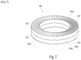
- each locking washer 350 has two toothed crowns 352 and 354 which overlap and come into contact.
- Crowns 352 and 354 have external faces 352a and 354b which rest against threaded member 300 and counterbore 265, respectively.
- crowns 352 and 354 are provided, on their facing faces 352b and 354a, with notches 355 arranged such that a relative rotation of the crowns 322 and 324 in the direction of unscrewing the threaded element 300 is accompanied, by cam effect, by a separation of the crowns opposing the unscrewing.
- the notches 355 are inclined at an angle ⁇ , relative to a transverse plane P of the washer 350, greater than that of the helix angle ⁇ of the thread, which causes positive and effective locking of the threaded element.
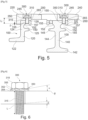
- the edge profiles 120 each comprise a sole 122 having the general shape of an L-shaped angle iron, as can be seen in the figure 5 in particular.
- Each edge profile 120 has a groove 150 intended to receive a sealing gasket (not shown). This groove 150 has a fallen edge 157 delimiting its opening at the top.
- the profile 120 has a rib 125 which delimits the groove 150 at the bottom.
- the profiles 120 and 140 have holes 155 which open into the grooves 150.
- Each groove 150 has an internal surface 152, onto which the holes 155 open, concave towards the inside of the groove 150.
- the threaded elements 300 have a length L such that their end 301 extends at least partially outside the bore 155 inside the groove 150.
- the threaded element 300 can extend outside the bore 155 into the groove 150 by a distance ⁇ greater than or equal to 2 mm, and thus come into contact with the sealing gasket located there.
- the intermediate profiles 140 each comprise a sole 142 having the general shape of an inverted T.
- Each intermediate profile 140 has two grooves 150, open in opposite directions, in which the sealing gaskets are received. Drillings 155 open inside these grooves 150, in a similar manner to what has been described for the edge profiles 120.
- the holes 155 opening into one of the grooves 150 are offset, along the longitudinal axis of the profile 140, relative to the holes opening into the other groove 150.
- the holes 155 opening into one of the grooves 150 occupy the same position, along the longitudinal axis of the profile, as the holes 155 opening into the other groove 150, as illustrated in figure 5 .
- the threaded elements 300 can be engaged alternately in the holes 155.
- head screws can be replaced with threaded rods and nuts.
Landscapes
- Engineering & Computer Science (AREA)
- Architecture (AREA)
- Civil Engineering (AREA)
- Structural Engineering (AREA)
- Gasket Seals (AREA)
- Connection Of Plates (AREA)
Description
- La présente invention concerne les équipements d'ouvrage d'art et plus précisément les joints de dilatation.
- Les joints de dilatation carrossables sont utilisés pour raccorder deux portions de revêtement routier susceptibles de subir des déplacements relatifs. Ces joints sont agencés de manière à combler les jeux s'étendant entre les portions de revêtement concernées, permettant ainsi d'assurer la continuité du roulement.
- Les joints de dilatation comportent classiquement des plaques dentées métalliques fixées sur des profilés.
- La demande
DE 4433909A enseigne de fixer ces plaques dentées avec des vis. Cependant, étant exposées aux vibrations causées par le passage des véhicules, celles-ci risquent de se desserrer à l'usage. - Le brevet
EP1327026 enseigne d'éliminer ce risque en fixant les plaques dentées par soudage. Si cela apporte une solution efficace contre le risque de desserrement des vis, l'entretien du joint est rendu plus difficile et notamment le remplacement des garnitures d'étanchéité reliant les profilés. - Le brevet
KR 100 726 379 B1 - Un des buts de l'invention est ainsi de proposer un joint de dilatation qui soit fiable à l'usage et d'entretien aisé.
- L'invention vise à atteindre cet objectif et elle y parvient grâce à un joint de dilatation carrossable selon la revendication 1.
- Le joint selon l'invention comporte une garniture d'étanchéité reçue dans une gorge du profilé.
- L'utilisation des rondelles de blocage permet de maintenir bloqués en rotation les éléments filetés après qu'ils ont été serrés. Ces rondelles de blocage maintiennent durablement un effort de précontrainte dans les éléments filetés. Ainsi, l'invention réduit le risque de desserrement indésirable des éléments filetés, source de vibrations et de bruit.
- En outre, le fait que les plaques dentées soient maintenues par des éléments filetés sur les profilés permet une maintenance relativement rapide et aisée du joint de dilatation. Le changement de certaines pièces constitutives, telles que les garnitures d'étanchéité, est par conséquent facilité.
- Selon l'invention, les éléments filetés sont engagés dans des perçages du profilé débouchant dans ladite gorge, ce qui permet de maximiser la longueur de prise des vis.
- Les éléments filetés viennent au contact de la garniture d'étanchéité.
- La surface de la gorge sur laquelle débouche les perçages est concave vers l'intérieur de la gorge, et les éléments filetés ont une longueur telle que leur extrémité s'étende au moins partiellement hors du perçage à l'intérieur de la gorge.
- Le profilé peut être un profilé de rive comportant une unique gorge de réception de la garniture d'étanchéité. Le profilé peut encore être un profilé intermédiaire comportant deux gorges, ouvertes dans des directions opposées, de réception de garnitures d'étanchéité respectives. Ce profilé peut avoir des perçages qui débouchent à l'intérieur des gorges. Les perçages débouchant dans l'une des gorges peuvent être décalés selon l'axe longitudinal du profilé par rapport aux perçages débouchant dans l'autre gorge.
- En variante, les perçages débouchant dans l'une des gorges occupent la même position selon l'axe longitudinal du profilé que les perçages débouchant dans l'autre gorge, les éléments filetés étant engagés alternativement dans les perçages associés auxdites gorges. Cela peut permettre un montage des plaques dentées selon deux configurations inverses sur le profilé intermédiaire.
- La ou chaque gorge peut comporter un bord tombé délimitant supérieurement son ouverture; les perçages de réception des éléments filetés peuvent déboucher en arrière de ce bord tombé. Les éléments filetés peuvent être des vis à tête ou des écrous, et de préférence sont des vis à tête.
- Le joint peut comporter au moins deux plaques de roulement dentées disposées dans le prolongement l'une de l'autre, avec de préférence un recouvrement longitudinal de l'une des plaques par l'autre ; chacune des plaques peut présenter au moins une dent d'extrémité, les bases des dents d'extrémité des deux plaques dentées venant en contact.
- Les rondelles de blocage peuvent être élastiques, de façon à pouvoir être déformées à plat en formant ressort entre les éléments filetés et le fond des lamages. Cela permet d'introduire la précontrainte recherchée dans les éléments filetés.
- Les rondelles de blocage peuvent être à effet de came. De telles rondelles de blocage sont par exemple décrites dans la demande
US20180023614 et sont commercialisées par la société NORD LOCK sous la dénomination « Nord Lock Washer X». - De préférence, les rondelles de blocage comportent chacune deux couronnes crantées dont l'une au moins est élastique, de préférence les deux sont élastiques, les couronnes étant pourvues sur leurs faces en regard de crans disposés de telle sorte qu'une rotation relative des couronnes dans le sens d'un dévissage de l'élément fileté s'accompagne, par effet de came, d'un écartement des couronnes s'opposant au dévissage.
- Les couronnes peuvent présenter chacune une forme sensiblement tronconique au repos. Les crans exerçant l'effet de came, sont de préférence inclinés d'un angle, par rapport à un plan transversal de la rondelle de blocage perpendiculaire à l'axe de l'élément fileté, supérieur à celui de l'angle d'hélice de l'élément fileté.
- L'invention pourra être mieux comprise à la lecture de la description détaillée qui va suivre, d'exemples de mise en oeuvre non limitatifs de l'invention, et à l'examen du dessin annexé, sur lequel :
- [
Fig 1 ] lafigure 1 est une vue partielle et schématique, en perspective, d'un exemple de joint de dilatation selon l'invention, - [
Fig 2 ] lafigure 2 est une vue de dessus du joint illustré à lafigure 1 , - [
Fig 3 ] lafigure 3 représente isolément, en perspective, un exemple de plaques dentées correspondant à une plaque de rive, vues de dessus et de dessous, - [
Fig 4 ] lafigure 4 est une vue analogue à lafigure 3 d'une variante de plaque dentée correspondant à une plaque intermédiaire, - [
Fig 5 ] lafigure 5 est une coupe transversale et partielle d'un exemple de joint de dilatation selon l'invention, - [
Fig 6 ] lafigure 6 représente en coupe axiale un élément fileté et une rondelle de blocage associée selon l'invention, et - [
Fig 7 ] lafigure 7 représente isolément, en perspective, un couple de couronnes crantées d'une rondelle de blocage. - On a représenté aux
figures 1 à 5 , un exemple de joint de dilatation 1 carrossable selon l'invention. - Ce joint 1 comporte un ensemble de profilés 100 destiné à relier deux portions de revêtement routier (non illustrées).
- Dans l'exemple considéré, le joint 1 comporte ainsi deux profilés de rive 120 et plusieurs profilés intermédiaires 140 disposés entre les profilés de rive 120.
- Le joint 1 comporte plusieurs plaques de roulement dentées 200, fixées par des éléments filetés 300 sur les profilés 120 et 140.
- Les plaques de roulement 200 comportent chacune une pluralité de dents 250 s'étendant en direction d'une plaque adjacente 200.
- Les dents 250 de deux plaques adjacentes 200 sont disposées de manière à s'imbriquer, lorsque les deux plaques se rapprochent.
- Dans le mode de réalisation illustré, le joint de dilatation 1 comporte deux types de plaques de roulement 200, à savoir :
- Des plaques 220 fixées sur les profilés de rive 120, ces plaques comportant des dents 205 s'étendant d'un seul côté de celles-ci, et
- des plaques 240 fixées sur les profilés intermédiaires 140, ces plaques comportant des dents s'étendant de deux côtés opposés de celles-ci.
- Chaque plaque de roulement 200 présente des perçages 245 pourvus de lamages 265 dans lesquels les éléments filetés 300 sont reçus.
- Selon la longueur du joint 1, plusieurs plaques de roulement dentées 200 peuvent être disposées dans le prolongement les unes des autres. Deux plaques successives 200 présentent de préférence un recouvrement longitudinal, comme visible sur la
figure 2 . Ce recouvrement peut se faire de telle sorte que les bases 255 des dents d'extrémité viennent en contact mutuel. Dans le mode de réalisation illustré, les éléments filetés 300 sont des vis dotées chacune d'une tête 310 et d'une tige filetée 315. - Des rondelles de blocage 350 sont interposées axialement entre les éléments filetés 300 et le fond des lamages 265, permettant ainsi de s'opposer à un desserrement des éléments filetés 300. Les rondelles de blocage sont élastiquement déformables, de façon à pouvoir être déformées à plat et former ressort entre les éléments filetés 300 et le fond des lamages 265. Comme illustré à la
figure 6 , chaque rondelle de blocage 350 comporte deux couronnes crantées 352 et 354 qui se superposent et viennent en contact. - Les couronnes 352 et 354 présentent des faces externes 352a et 354b qui reposent contre l'élément fileté 300 et le lamage 265, respectivement.
- En outre, les couronnes 352 et 354 sont pourvues, sur leurs faces 352b et 354a en regard, de crans 355 disposés de telle sorte qu'une rotation relative des couronnes 322 et 324 dans le sens d'un dévissage de l'élément fileté 300 s'accompagne, par effet de came, d'un écartement des couronnes s'opposant au dévissage.
- Comme cela est illustré à la
figure 6 , les crans 355 sont inclinés d'un angle α, par rapport à un plan transversal P de la rondelle 350, supérieur à celui de l'angle β d'hélice du filetage, ce qui provoque un verrouillage positif et efficace de l'élément fileté. - Les profilés de rive 120 comprennent chacun une semelle 122 ayant la forme générale d'une cornière en L, comme on peut le voir sur la
figure 5 notamment. Chaque profilé de rive 120 présente une gorge 150 destinée à recevoir une garniture d'étanchéité (non représentée). Cette gorge 150 comporte un bord tombé 157 délimitant supérieurement son ouverture. Le profilé 120 présente une nervure 125 qui délimite inférieurement la gorge 150. - Les profilés 120 et 140 présentent des perçages 155 qui débouchent dans les gorges 150. Chaque gorge 150 présente une surface interne 152, sur laquelle débouche les perçages 155, concave vers l'intérieur de la gorge 150.
- Les éléments filetés 300 présentent une longueur L telle que leur extrémité 301 s'étende au moins partiellement hors du perçage 155 à l'intérieur de la gorge 150. L'élément fileté 300 peut s'étendre hors du perçage 155 dans la gorge 150 d'une distance δ supérieure ou égale à 2mm, et ainsi venir au contact de la garniture d'étanchéité que s'y trouve.
- Les profilés intermédiaires 140 comprennent chacun une semelle 142 ayant la forme générale d'un T inversé.
- Chaque profilé intermédiaire 140 comporte deux gorges 150, ouvertes dans des directions opposées, dans lesquelles les garnitures d'étanchéité sont reçues. Des perçages 155 débouchent à l'intérieur de ces gorges 150, de façon similaire à ce qui a été décrit pour les profilés de rive 120.
- Dans l'exemple illustré aux
figures 1 et 2 , les perçages 155 débouchant dans l'une des gorges 150 sont décalés, selon l'axe longitudinal du profilé 140, par rapport aux perçages débouchant dans l'autre gorge 150. - En variante, les perçages 155 débouchant dans l'une des gorges 150 occupent la même position, selon l'axe longitudinal du profilé, que les perçages 155 débouchant dans l'autre gorge 150, comme cela est illustré à la
figure 5 . Dans ce cas, les éléments filetés 300 peuvent être engagés alternativement dans les perçages 155. - Bien entendu, l'invention n'est pas limitée aux exemples qui viennent d'être décrits.
- Par exemple, les vis à tête peuvent être remplacées par des tiges filetées et des écrous.
Claims (9)
- Joint de dilatation carrossable (1), comportant :- au moins un profilé de joint (100),- au moins une plaque de roulement dentée (200), cette plaque présentant des perçages (245) pourvus de lamages (265),- des éléments filetés (300) de fixation de la plaque de roulement sur le profilé,- des rondelles de blocage (350), interposées axialement entre les éléments filetés (300) et le fond des lamages (265), pour s'opposer à un desserrement des éléments filetés (300),
caractérisé en ce que les rondelles de blocage (350) sont à effet de came,- une garniture d'étanchéité est reçue dans une gorge (150) du profilé (100), les éléments filetés (300) étant engagés dans des perçages (155) du profilé (100) débouchant dans ladite gorge (150), la surface (152) de la gorge (150) sur laquelle débouche les perçages (155) étant concave vers l'intérieur de la gorge (150), les éléments filetés (300) ayant une longueur (L) telle que leur extrémité (301) s'étend au moins partiellement hors du perçage (105) à l'intérieur de la gorge (150), les éléments filetés venant au contact de la garniture d'étanchéité. - Joint selon la revendication1, le profilé (100) étant un profilé de rive (120) comportant une unique gorge (150) de réception de la garniture d'étanchéité.
- Joint selon la revendication 1, le profilé (100) étant un profilé intermédiaire (140) comportant deux gorges (150), ouvertes dans des directions opposées, de réception de garnitures d'étanchéité, chaque profilé (140) ayant des perçages (155) qui débouchent à l'intérieur desdites gorges (150).
- Joint selon l'une quelconque des revendications 1 à 3, la ou chaque gorge (150) comportant un bord tombé (157) délimitant supérieurement son ouverture, le perçage (155) de réception des éléments filetés (300) débouchant en arrière de ce bord tombé (157).
- Joint selon l'une quelconque des revendications précédentes, les éléments filetés (300) étant des vis à tête (310 ; 315).
- Joint selon l'une quelconque des revendications précédentes, comportant au moins deux plaques de roulement dentées (220 ; 240) disposées dans le prolongement l'une de l'autre, avec de préférence un recouvrement longitudinal de l'une des plaques par l'autre; chacune des plaques présentant au moins une dent d'extrémité (250), les bases (255) des dents d'extrémité des deux plaques dentées venant en contact.
- Joint selon l'une quelconque des revendications précédentes, les rondelles de blocage (350) étant élastiques.
- Joint selon l'une quelconque des revendications précédentes, les rondelles de blocage comportant chacune deux couronnes (352 ; 354) crantées dont l'une au moins est élastique, de préférence les deux sont élastiques, les couronnes (352 ; 354) étant pourvues sur leurs faces (352b ; 354a) en regard de crans (355) disposés de telle sorte qu'une rotation relative des couronnes (352 ; 354) dans le sens d'un dévissage de l'élément fileté (300) s'accompagne par effet de came d'un écartement des couronnes (352 ; 354) s'opposant au dévissage.
- Joint selon la revendication 8, les crans (355) étant inclinés d'un angle (α), par rapport à un plan transversal de la rondelle de blocage (350) perpendiculaire à l'axe de l'élément fileté, supérieur à celui de l'angle (β) d'hélice de l'élément fileté (300).
Applications Claiming Priority (2)
| Application Number | Priority Date | Filing Date | Title |
|---|---|---|---|
| FR1904931A FR3096060B1 (fr) | 2019-05-13 | 2019-05-13 | Joint de dilatation carrossable |
| PCT/EP2020/063223 WO2020229487A1 (fr) | 2019-05-13 | 2020-05-12 | Joint de dilatation carrossable |
Publications (2)
| Publication Number | Publication Date |
|---|---|
| EP3969663A1 EP3969663A1 (fr) | 2022-03-23 |
| EP3969663B1 true EP3969663B1 (fr) | 2024-11-20 |
Family
ID=68987729
Family Applications (1)
| Application Number | Title | Priority Date | Filing Date |
|---|---|---|---|
| EP20724148.0A Active EP3969663B1 (fr) | 2019-05-13 | 2020-05-12 | Joint de dilatation carrossable |
Country Status (3)
| Country | Link |
|---|---|
| EP (1) | EP3969663B1 (fr) |
| FR (1) | FR3096060B1 (fr) |
| WO (1) | WO2020229487A1 (fr) |
Families Citing this family (1)
| Publication number | Priority date | Publication date | Assignee | Title |
|---|---|---|---|---|
| CN114935373B (zh) * | 2022-07-25 | 2023-03-17 | 南京大学 | 一种桥梁伸缩缝病害数据模拟采集系统 |
Citations (5)
| Publication number | Priority date | Publication date | Assignee | Title |
|---|---|---|---|---|
| DE2124966A1 (de) | 1971-05-19 | 1972-12-07 | Rheinstahl Ag, 4300 Essen | Fahrbahnübergang für Dehnfugen in Straßen und Gehwegen |
| WO2002027102A1 (fr) | 2000-09-26 | 2002-04-04 | Maurer Söhne Gmbh & Co. Kg | Systeme de plaques dentees destine a un dispositif de pontage de joints de dilatation |
| KR100488624B1 (ko) | 2004-04-13 | 2005-05-11 | 주식회사 동아기술공사 | 소음/충격 완화 및 볼트/너트 풀림방지 수단을 구비한신축 이음장치 및 그 시공방법 |
| US20180023614A1 (en) | 2015-02-04 | 2018-01-25 | Nord-Lock Ab | Wedge locking washer with increased corrosion resistance and method for its manufacture |
| DE102017105092A1 (de) | 2017-03-10 | 2018-09-13 | Mageba S.A. | Überbrückungsvorrichtung |
Family Cites Families (2)
| Publication number | Priority date | Publication date | Assignee | Title |
|---|---|---|---|---|
| DE4433909C2 (de) | 1994-09-22 | 1997-11-27 | Alfred Hartkorn | Fugenüberbrückungsvorrichtung |
| KR100726379B1 (ko) * | 2006-02-24 | 2007-06-08 | 주식회사 에스코알티에스 | 교량용 알루미늄 신축이음장치 |
-
2019
- 2019-05-13 FR FR1904931A patent/FR3096060B1/fr active Active
-
2020
- 2020-05-12 WO PCT/EP2020/063223 patent/WO2020229487A1/fr not_active Ceased
- 2020-05-12 EP EP20724148.0A patent/EP3969663B1/fr active Active
Patent Citations (5)
| Publication number | Priority date | Publication date | Assignee | Title |
|---|---|---|---|---|
| DE2124966A1 (de) | 1971-05-19 | 1972-12-07 | Rheinstahl Ag, 4300 Essen | Fahrbahnübergang für Dehnfugen in Straßen und Gehwegen |
| WO2002027102A1 (fr) | 2000-09-26 | 2002-04-04 | Maurer Söhne Gmbh & Co. Kg | Systeme de plaques dentees destine a un dispositif de pontage de joints de dilatation |
| KR100488624B1 (ko) | 2004-04-13 | 2005-05-11 | 주식회사 동아기술공사 | 소음/충격 완화 및 볼트/너트 풀림방지 수단을 구비한신축 이음장치 및 그 시공방법 |
| US20180023614A1 (en) | 2015-02-04 | 2018-01-25 | Nord-Lock Ab | Wedge locking washer with increased corrosion resistance and method for its manufacture |
| DE102017105092A1 (de) | 2017-03-10 | 2018-09-13 | Mageba S.A. | Überbrückungsvorrichtung |
Non-Patent Citations (2)
| Title |
|---|
| ANONYMOUS: "Talbrücke Albrechtsgraben (Deutschland), Version 2012.09", MAGEBA – PROJEKTINFORMATION, 1 September 2012 (2012-09-01), XP093308802, Retrieved from the Internet <URL:https://www.mageba-group.com/cz/data/docs/de_CZ/2305/Refsheet-Albrechtsgraben-ch-de.pdf> |
| D4: "Brückenbau Construction & Engineering", 2015, VERLAGSGRUPPE WIEDERSPAHN, ISBN: SSN 1867-643X |
Also Published As
| Publication number | Publication date |
|---|---|
| FR3096060A1 (fr) | 2020-11-20 |
| EP3969663A1 (fr) | 2022-03-23 |
| WO2020229487A1 (fr) | 2020-11-19 |
| FR3096060B1 (fr) | 2021-06-18 |
Similar Documents
| Publication | Publication Date | Title |
|---|---|---|
| EP1203856B1 (fr) | Couvre-joint | |
| EP1481653A1 (fr) | Prothèse de coude | |
| EP2917969B1 (fr) | Dispositif de fixation d'une cosse de raccordement electrique sur un support | |
| EP2789888B1 (fr) | Dispositif de serrage pour l'accouplement étanche de tubes lisses | |
| FR2790046A1 (fr) | Dispositif de fixation de deux panneaux ou analogues forme de deux pieces cooperantes | |
| EP3825594A1 (fr) | Collier de serrage | |
| EP2571113B1 (fr) | Dispositif de fixation et de connexion rapide pour connecteur en deux parties | |
| EP3969663A1 (fr) | Joint de dilatation carrossable | |
| FR2961884A1 (fr) | Collier de serrage a soyage | |
| EP2502806B1 (fr) | Ensemble d'équipement de véhicule automobile et un procédé de montage associé | |
| FR2983544A1 (fr) | Rondelle de blocage renforcee | |
| FR3098884A1 (fr) | Collier de serrage à barre de retenue | |
| FR3036361A1 (fr) | Element de fixation ameliore | |
| FR2945329A1 (fr) | Rotor de soufflante d'un turboracteur d'avion | |
| FR2549915A1 (fr) | Perfectionnements aux systemes de vissage comprenant un ecrou a embase et aux composants de ces systemes | |
| FR2948276A1 (fr) | Systeme d'osteosynthese, notamment pour osteosynthese rachidienne | |
| EP2359045B1 (fr) | Ensemble d'étanchéité et jonction tubulaire correspondante | |
| WO2000031846A1 (fr) | Presse-etoupe a garniture d'etancheite et dents de serrage epaisses | |
| EP3061979B1 (fr) | Insert à sertir sur une pièce à fixer sur un support et ensemble de fixation comprenant un tel insert | |
| FR2634070A1 (fr) | Connecteur isole pour cables electriques | |
| FR2889773A1 (fr) | Ensemble de rails rigides pour dispositifs d'alimentation electrique par prise mobile de courant | |
| FR2828914A1 (fr) | Dispositif d'assemblage | |
| FR2663099A1 (fr) | Support elastique comportant une couche d'elastomere et deux pieces d'extremite, notamment pour moteur marin. | |
| FR2957990A1 (fr) | Rondelle de controle de serrage, ensemble de serrage et collier de prise en charge sur conduite | |
| FR3007495A1 (fr) | Ensemble pour la realisation d'un joint filete pour le forage et l'exploitation des puits d'hydrocarbures, joint filete et procede de realisation d'un tel joint |
Legal Events
| Date | Code | Title | Description |
|---|---|---|---|
| STAA | Information on the status of an ep patent application or granted ep patent |
Free format text: STATUS: UNKNOWN |
|
| STAA | Information on the status of an ep patent application or granted ep patent |
Free format text: STATUS: THE INTERNATIONAL PUBLICATION HAS BEEN MADE |
|
| PUAI | Public reference made under article 153(3) epc to a published international application that has entered the european phase |
Free format text: ORIGINAL CODE: 0009012 |
|
| STAA | Information on the status of an ep patent application or granted ep patent |
Free format text: STATUS: REQUEST FOR EXAMINATION WAS MADE |
|
| 17P | Request for examination filed |
Effective date: 20211213 |
|
| AK | Designated contracting states |
Kind code of ref document: A1 Designated state(s): AL AT BE BG CH CY CZ DE DK EE ES FI FR GB GR HR HU IE IS IT LI LT LU LV MC MK MT NL NO PL PT RO RS SE SI SK SM TR |
|
| RIN1 | Information on inventor provided before grant (corrected) |
Inventor name: MICHOT, ANTHONY Inventor name: SALMON, PHILIPPE |
|
| DAV | Request for validation of the european patent (deleted) | ||
| DAX | Request for extension of the european patent (deleted) | ||
| STAA | Information on the status of an ep patent application or granted ep patent |
Free format text: STATUS: EXAMINATION IS IN PROGRESS |
|
| 17Q | First examination report despatched |
Effective date: 20230613 |
|
| P01 | Opt-out of the competence of the unified patent court (upc) registered |
Effective date: 20230530 |
|
| GRAP | Despatch of communication of intention to grant a patent |
Free format text: ORIGINAL CODE: EPIDOSNIGR1 |
|
| STAA | Information on the status of an ep patent application or granted ep patent |
Free format text: STATUS: GRANT OF PATENT IS INTENDED |
|
| INTG | Intention to grant announced |
Effective date: 20240715 |
|
| GRAS | Grant fee paid |
Free format text: ORIGINAL CODE: EPIDOSNIGR3 |
|
| GRAA | (expected) grant |
Free format text: ORIGINAL CODE: 0009210 |
|
| STAA | Information on the status of an ep patent application or granted ep patent |
Free format text: STATUS: THE PATENT HAS BEEN GRANTED |
|
| AK | Designated contracting states |
Kind code of ref document: B1 Designated state(s): AL AT BE BG CH CY CZ DE DK EE ES FI FR GB GR HR HU IE IS IT LI LT LU LV MC MK MT NL NO PL PT RO RS SE SI SK SM TR |
|
| REG | Reference to a national code |
Ref country code: GB Ref legal event code: FG4D Free format text: NOT ENGLISH |
|
| REG | Reference to a national code |
Ref country code: CH Ref legal event code: EP |
|
| REG | Reference to a national code |
Ref country code: DE Ref legal event code: R096 Ref document number: 602020041643 Country of ref document: DE |
|
| REG | Reference to a national code |
Ref country code: IE Ref legal event code: FG4D Free format text: LANGUAGE OF EP DOCUMENT: FRENCH |
|
| REG | Reference to a national code |
Ref country code: LT Ref legal event code: MG9D |
|
| REG | Reference to a national code |
Ref country code: NL Ref legal event code: MP Effective date: 20241120 |
|
| PG25 | Lapsed in a contracting state [announced via postgrant information from national office to epo] |
Ref country code: PT Free format text: LAPSE BECAUSE OF FAILURE TO SUBMIT A TRANSLATION OF THE DESCRIPTION OR TO PAY THE FEE WITHIN THE PRESCRIBED TIME-LIMIT Effective date: 20250320 Ref country code: IS Free format text: LAPSE BECAUSE OF FAILURE TO SUBMIT A TRANSLATION OF THE DESCRIPTION OR TO PAY THE FEE WITHIN THE PRESCRIBED TIME-LIMIT Effective date: 20250320 Ref country code: HR Free format text: LAPSE BECAUSE OF FAILURE TO SUBMIT A TRANSLATION OF THE DESCRIPTION OR TO PAY THE FEE WITHIN THE PRESCRIBED TIME-LIMIT Effective date: 20241120 |
|
| PG25 | Lapsed in a contracting state [announced via postgrant information from national office to epo] |
Ref country code: NL Free format text: LAPSE BECAUSE OF FAILURE TO SUBMIT A TRANSLATION OF THE DESCRIPTION OR TO PAY THE FEE WITHIN THE PRESCRIBED TIME-LIMIT Effective date: 20241120 Ref country code: FI Free format text: LAPSE BECAUSE OF FAILURE TO SUBMIT A TRANSLATION OF THE DESCRIPTION OR TO PAY THE FEE WITHIN THE PRESCRIBED TIME-LIMIT Effective date: 20241120 |
|
| REG | Reference to a national code |
Ref country code: AT Ref legal event code: MK05 Ref document number: 1743669 Country of ref document: AT Kind code of ref document: T Effective date: 20241120 |
|
| PG25 | Lapsed in a contracting state [announced via postgrant information from national office to epo] |
Ref country code: BG Free format text: LAPSE BECAUSE OF FAILURE TO SUBMIT A TRANSLATION OF THE DESCRIPTION OR TO PAY THE FEE WITHIN THE PRESCRIBED TIME-LIMIT Effective date: 20241120 |
|
| PG25 | Lapsed in a contracting state [announced via postgrant information from national office to epo] |
Ref country code: ES Free format text: LAPSE BECAUSE OF FAILURE TO SUBMIT A TRANSLATION OF THE DESCRIPTION OR TO PAY THE FEE WITHIN THE PRESCRIBED TIME-LIMIT Effective date: 20241120 |
|
| PG25 | Lapsed in a contracting state [announced via postgrant information from national office to epo] |
Ref country code: NO Free format text: LAPSE BECAUSE OF FAILURE TO SUBMIT A TRANSLATION OF THE DESCRIPTION OR TO PAY THE FEE WITHIN THE PRESCRIBED TIME-LIMIT Effective date: 20250220 |
|
| PG25 | Lapsed in a contracting state [announced via postgrant information from national office to epo] |
Ref country code: LV Free format text: LAPSE BECAUSE OF FAILURE TO SUBMIT A TRANSLATION OF THE DESCRIPTION OR TO PAY THE FEE WITHIN THE PRESCRIBED TIME-LIMIT Effective date: 20241120 Ref country code: AT Free format text: LAPSE BECAUSE OF FAILURE TO SUBMIT A TRANSLATION OF THE DESCRIPTION OR TO PAY THE FEE WITHIN THE PRESCRIBED TIME-LIMIT Effective date: 20241120 Ref country code: GR Free format text: LAPSE BECAUSE OF FAILURE TO SUBMIT A TRANSLATION OF THE DESCRIPTION OR TO PAY THE FEE WITHIN THE PRESCRIBED TIME-LIMIT Effective date: 20250221 |
|
| PG25 | Lapsed in a contracting state [announced via postgrant information from national office to epo] |
Ref country code: PL Free format text: LAPSE BECAUSE OF FAILURE TO SUBMIT A TRANSLATION OF THE DESCRIPTION OR TO PAY THE FEE WITHIN THE PRESCRIBED TIME-LIMIT Effective date: 20241120 |
|
| PG25 | Lapsed in a contracting state [announced via postgrant information from national office to epo] |
Ref country code: RS Free format text: LAPSE BECAUSE OF FAILURE TO SUBMIT A TRANSLATION OF THE DESCRIPTION OR TO PAY THE FEE WITHIN THE PRESCRIBED TIME-LIMIT Effective date: 20250220 |
|
| PG25 | Lapsed in a contracting state [announced via postgrant information from national office to epo] |
Ref country code: SM Free format text: LAPSE BECAUSE OF FAILURE TO SUBMIT A TRANSLATION OF THE DESCRIPTION OR TO PAY THE FEE WITHIN THE PRESCRIBED TIME-LIMIT Effective date: 20241120 |
|
| PG25 | Lapsed in a contracting state [announced via postgrant information from national office to epo] |
Ref country code: DK Free format text: LAPSE BECAUSE OF FAILURE TO SUBMIT A TRANSLATION OF THE DESCRIPTION OR TO PAY THE FEE WITHIN THE PRESCRIBED TIME-LIMIT Effective date: 20241120 |
|
| PGFP | Annual fee paid to national office [announced via postgrant information from national office to epo] |
Ref country code: GB Payment date: 20250527 Year of fee payment: 6 |
|
| PGFP | Annual fee paid to national office [announced via postgrant information from national office to epo] |
Ref country code: IT Payment date: 20250527 Year of fee payment: 6 |
|
| PG25 | Lapsed in a contracting state [announced via postgrant information from national office to epo] |
Ref country code: EE Free format text: LAPSE BECAUSE OF FAILURE TO SUBMIT A TRANSLATION OF THE DESCRIPTION OR TO PAY THE FEE WITHIN THE PRESCRIBED TIME-LIMIT Effective date: 20241120 |
|
| PGFP | Annual fee paid to national office [announced via postgrant information from national office to epo] |
Ref country code: FR Payment date: 20250528 Year of fee payment: 6 |
|
| PG25 | Lapsed in a contracting state [announced via postgrant information from national office to epo] |
Ref country code: RO Free format text: LAPSE BECAUSE OF FAILURE TO SUBMIT A TRANSLATION OF THE DESCRIPTION OR TO PAY THE FEE WITHIN THE PRESCRIBED TIME-LIMIT Effective date: 20241120 |
|
| PG25 | Lapsed in a contracting state [announced via postgrant information from national office to epo] |
Ref country code: SK Free format text: LAPSE BECAUSE OF FAILURE TO SUBMIT A TRANSLATION OF THE DESCRIPTION OR TO PAY THE FEE WITHIN THE PRESCRIBED TIME-LIMIT Effective date: 20241120 |
|
| PG25 | Lapsed in a contracting state [announced via postgrant information from national office to epo] |
Ref country code: CZ Free format text: LAPSE BECAUSE OF FAILURE TO SUBMIT A TRANSLATION OF THE DESCRIPTION OR TO PAY THE FEE WITHIN THE PRESCRIBED TIME-LIMIT Effective date: 20241120 |
|
| REG | Reference to a national code |
Ref country code: DE Ref legal event code: R026 Ref document number: 602020041643 Country of ref document: DE |
|
| PLBI | Opposition filed |
Free format text: ORIGINAL CODE: 0009260 |
|
| PLAX | Notice of opposition and request to file observation + time limit sent |
Free format text: ORIGINAL CODE: EPIDOSNOBS2 |
|
| PG25 | Lapsed in a contracting state [announced via postgrant information from national office to epo] |
Ref country code: SE Free format text: LAPSE BECAUSE OF FAILURE TO SUBMIT A TRANSLATION OF THE DESCRIPTION OR TO PAY THE FEE WITHIN THE PRESCRIBED TIME-LIMIT Effective date: 20241120 |
|
| 26 | Opposition filed |
Opponent name: MAURER SE Effective date: 20250820 |
|
| REG | Reference to a national code |
Ref country code: DE Ref legal event code: R119 Ref document number: 602020041643 Country of ref document: DE |
|
| REG | Reference to a national code |
Ref country code: CH Ref legal event code: H13 Free format text: ST27 STATUS EVENT CODE: U-0-0-H10-H13 (AS PROVIDED BY THE NATIONAL OFFICE) Effective date: 20251223 |
|
| PLBB | Reply of patent proprietor to notice(s) of opposition received |
Free format text: ORIGINAL CODE: EPIDOSNOBS3 |
|
| PG25 | Lapsed in a contracting state [announced via postgrant information from national office to epo] |
Ref country code: LU Free format text: LAPSE BECAUSE OF NON-PAYMENT OF DUE FEES Effective date: 20250512 |
|
| PG25 | Lapsed in a contracting state [announced via postgrant information from national office to epo] |
Ref country code: CH Free format text: LAPSE BECAUSE OF NON-PAYMENT OF DUE FEES Effective date: 20250531 |
|
| REG | Reference to a national code |
Ref country code: BE Ref legal event code: MM Effective date: 20250531 |
|
| PG25 | Lapsed in a contracting state [announced via postgrant information from national office to epo] |
Ref country code: MC Free format text: LAPSE BECAUSE OF FAILURE TO SUBMIT A TRANSLATION OF THE DESCRIPTION OR TO PAY THE FEE WITHIN THE PRESCRIBED TIME-LIMIT Effective date: 20241120 |
|
| PG25 | Lapsed in a contracting state [announced via postgrant information from national office to epo] |
Ref country code: IE Free format text: LAPSE BECAUSE OF NON-PAYMENT OF DUE FEES Effective date: 20250512 Ref country code: DE Free format text: LAPSE BECAUSE OF NON-PAYMENT OF DUE FEES Effective date: 20251202 |
|
| PG25 | Lapsed in a contracting state [announced via postgrant information from national office to epo] |
Ref country code: BE Free format text: LAPSE BECAUSE OF NON-PAYMENT OF DUE FEES Effective date: 20250531 |