EP3969372B1 - Landeplattform für unbemannte luftfahrzeuge - Google Patents
Landeplattform für unbemannte luftfahrzeuge Download PDFInfo
- Publication number
- EP3969372B1 EP3969372B1 EP20726790.7A EP20726790A EP3969372B1 EP 3969372 B1 EP3969372 B1 EP 3969372B1 EP 20726790 A EP20726790 A EP 20726790A EP 3969372 B1 EP3969372 B1 EP 3969372B1
- Authority
- EP
- European Patent Office
- Prior art keywords
- central
- module
- sockets
- electroconductive
- modules
- Prior art date
- Legal status (The legal status is an assumption and is not a legal conclusion. Google has not performed a legal analysis and makes no representation as to the accuracy of the status listed.)
- Active
Links
Images



Classifications
-
- B—PERFORMING OPERATIONS; TRANSPORTING
- B60—VEHICLES IN GENERAL
- B60L—PROPULSION OF ELECTRICALLY-PROPELLED VEHICLES; SUPPLYING ELECTRIC POWER FOR AUXILIARY EQUIPMENT OF ELECTRICALLY-PROPELLED VEHICLES; ELECTRODYNAMIC BRAKE SYSTEMS FOR VEHICLES IN GENERAL; MAGNETIC SUSPENSION OR LEVITATION FOR VEHICLES; MONITORING OPERATING VARIABLES OF ELECTRICALLY-PROPELLED VEHICLES; ELECTRIC SAFETY DEVICES FOR ELECTRICALLY-PROPELLED VEHICLES
- B60L3/00—Electric devices on electrically-propelled vehicles for safety purposes; Monitoring operating variables, e.g. speed, deceleration or energy consumption
-
- B—PERFORMING OPERATIONS; TRANSPORTING
- B60—VEHICLES IN GENERAL
- B60L—PROPULSION OF ELECTRICALLY-PROPELLED VEHICLES; SUPPLYING ELECTRIC POWER FOR AUXILIARY EQUIPMENT OF ELECTRICALLY-PROPELLED VEHICLES; ELECTRODYNAMIC BRAKE SYSTEMS FOR VEHICLES IN GENERAL; MAGNETIC SUSPENSION OR LEVITATION FOR VEHICLES; MONITORING OPERATING VARIABLES OF ELECTRICALLY-PROPELLED VEHICLES; ELECTRIC SAFETY DEVICES FOR ELECTRICALLY-PROPELLED VEHICLES
- B60L5/00—Current collectors for power supply lines of electrically-propelled vehicles
- B60L5/36—Current collectors for power supply lines of electrically-propelled vehicles with means for collecting current simultaneously from more than one conductor, e.g. from more than one phase
-
- B—PERFORMING OPERATIONS; TRANSPORTING
- B60—VEHICLES IN GENERAL
- B60L—PROPULSION OF ELECTRICALLY-PROPELLED VEHICLES; SUPPLYING ELECTRIC POWER FOR AUXILIARY EQUIPMENT OF ELECTRICALLY-PROPELLED VEHICLES; ELECTRODYNAMIC BRAKE SYSTEMS FOR VEHICLES IN GENERAL; MAGNETIC SUSPENSION OR LEVITATION FOR VEHICLES; MONITORING OPERATING VARIABLES OF ELECTRICALLY-PROPELLED VEHICLES; ELECTRIC SAFETY DEVICES FOR ELECTRICALLY-PROPELLED VEHICLES
- B60L53/00—Methods of charging batteries, specially adapted for electric vehicles; Charging stations or on-board charging equipment therefor; Exchange of energy storage elements in electric vehicles
- B60L53/10—Methods of charging batteries, specially adapted for electric vehicles; Charging stations or on-board charging equipment therefor; Exchange of energy storage elements in electric vehicles characterised by the energy transfer between the charging station and the vehicle
- B60L53/14—Conductive energy transfer
- B60L53/16—Connectors, e.g. plugs or sockets, specially adapted for charging electric vehicles
-
- B—PERFORMING OPERATIONS; TRANSPORTING
- B64—AIRCRAFT; AVIATION; COSMONAUTICS
- B64U—UNMANNED AERIAL VEHICLES [UAV]; EQUIPMENT THEREFOR
- B64U50/00—Propulsion; Power supply
- B64U50/30—Supply or distribution of electrical power
- B64U50/37—Charging when not in flight
-
- B—PERFORMING OPERATIONS; TRANSPORTING
- B64—AIRCRAFT; AVIATION; COSMONAUTICS
- B64U—UNMANNED AERIAL VEHICLES [UAV]; EQUIPMENT THEREFOR
- B64U70/00—Launching, take-off or landing arrangements
- B64U70/90—Launching from or landing on platforms
-
- B—PERFORMING OPERATIONS; TRANSPORTING
- B64—AIRCRAFT; AVIATION; COSMONAUTICS
- B64U—UNMANNED AERIAL VEHICLES [UAV]; EQUIPMENT THEREFOR
- B64U70/00—Launching, take-off or landing arrangements
- B64U70/90—Launching from or landing on platforms
- B64U70/92—Portable platforms
-
- B—PERFORMING OPERATIONS; TRANSPORTING
- B64—AIRCRAFT; AVIATION; COSMONAUTICS
- B64U—UNMANNED AERIAL VEHICLES [UAV]; EQUIPMENT THEREFOR
- B64U80/00—Transport or storage specially adapted for UAVs
- B64U80/20—Transport or storage specially adapted for UAVs with arrangements for servicing the UAV
- B64U80/25—Transport or storage specially adapted for UAVs with arrangements for servicing the UAV for recharging batteries; for refuelling
-
- H—ELECTRICITY
- H02—GENERATION; CONVERSION OR DISTRIBUTION OF ELECTRIC POWER
- H02J—ELECTRIC POWER NETWORKS; CIRCUIT ARRANGEMENTS OR SYSTEMS FOR SUPPLYING OR DISTRIBUTING ELECTRIC POWER; SYSTEMS FOR STORING ELECTRIC ENERGY
- H02J7/00—Circuit arrangements for charging or discharging batteries or for supplying loads from batteries
- H02J7/70—Circuit arrangements for charging or discharging batteries or for supplying loads from batteries characterised by the mechanical construction
-
- B—PERFORMING OPERATIONS; TRANSPORTING
- B60—VEHICLES IN GENERAL
- B60L—PROPULSION OF ELECTRICALLY-PROPELLED VEHICLES; SUPPLYING ELECTRIC POWER FOR AUXILIARY EQUIPMENT OF ELECTRICALLY-PROPELLED VEHICLES; ELECTRODYNAMIC BRAKE SYSTEMS FOR VEHICLES IN GENERAL; MAGNETIC SUSPENSION OR LEVITATION FOR VEHICLES; MONITORING OPERATING VARIABLES OF ELECTRICALLY-PROPELLED VEHICLES; ELECTRIC SAFETY DEVICES FOR ELECTRICALLY-PROPELLED VEHICLES
- B60L2200/00—Type of vehicles
- B60L2200/10—Air crafts
-
- Y—GENERAL TAGGING OF NEW TECHNOLOGICAL DEVELOPMENTS; GENERAL TAGGING OF CROSS-SECTIONAL TECHNOLOGIES SPANNING OVER SEVERAL SECTIONS OF THE IPC; TECHNICAL SUBJECTS COVERED BY FORMER USPC CROSS-REFERENCE ART COLLECTIONS [XRACs] AND DIGESTS
- Y02—TECHNOLOGIES OR APPLICATIONS FOR MITIGATION OR ADAPTATION AGAINST CLIMATE CHANGE
- Y02T—CLIMATE CHANGE MITIGATION TECHNOLOGIES RELATED TO TRANSPORTATION
- Y02T10/00—Road transport of goods or passengers
- Y02T10/60—Other road transportation technologies with climate change mitigation effect
- Y02T10/70—Energy storage systems for electromobility, e.g. batteries
-
- Y—GENERAL TAGGING OF NEW TECHNOLOGICAL DEVELOPMENTS; GENERAL TAGGING OF CROSS-SECTIONAL TECHNOLOGIES SPANNING OVER SEVERAL SECTIONS OF THE IPC; TECHNICAL SUBJECTS COVERED BY FORMER USPC CROSS-REFERENCE ART COLLECTIONS [XRACs] AND DIGESTS
- Y02—TECHNOLOGIES OR APPLICATIONS FOR MITIGATION OR ADAPTATION AGAINST CLIMATE CHANGE
- Y02T—CLIMATE CHANGE MITIGATION TECHNOLOGIES RELATED TO TRANSPORTATION
- Y02T10/00—Road transport of goods or passengers
- Y02T10/60—Other road transportation technologies with climate change mitigation effect
- Y02T10/7072—Electromobility specific charging systems or methods for batteries, ultracapacitors, supercapacitors or double-layer capacitors
-
- Y—GENERAL TAGGING OF NEW TECHNOLOGICAL DEVELOPMENTS; GENERAL TAGGING OF CROSS-SECTIONAL TECHNOLOGIES SPANNING OVER SEVERAL SECTIONS OF THE IPC; TECHNICAL SUBJECTS COVERED BY FORMER USPC CROSS-REFERENCE ART COLLECTIONS [XRACs] AND DIGESTS
- Y02—TECHNOLOGIES OR APPLICATIONS FOR MITIGATION OR ADAPTATION AGAINST CLIMATE CHANGE
- Y02T—CLIMATE CHANGE MITIGATION TECHNOLOGIES RELATED TO TRANSPORTATION
- Y02T90/00—Enabling technologies or technologies with a potential or indirect contribution to GHG emissions mitigation
- Y02T90/10—Technologies relating to charging of electric vehicles
- Y02T90/12—Electric charging stations
-
- Y—GENERAL TAGGING OF NEW TECHNOLOGICAL DEVELOPMENTS; GENERAL TAGGING OF CROSS-SECTIONAL TECHNOLOGIES SPANNING OVER SEVERAL SECTIONS OF THE IPC; TECHNICAL SUBJECTS COVERED BY FORMER USPC CROSS-REFERENCE ART COLLECTIONS [XRACs] AND DIGESTS
- Y02—TECHNOLOGIES OR APPLICATIONS FOR MITIGATION OR ADAPTATION AGAINST CLIMATE CHANGE
- Y02T—CLIMATE CHANGE MITIGATION TECHNOLOGIES RELATED TO TRANSPORTATION
- Y02T90/00—Enabling technologies or technologies with a potential or indirect contribution to GHG emissions mitigation
- Y02T90/10—Technologies relating to charging of electric vehicles
- Y02T90/14—Plug-in electric vehicles
Definitions
- the present invention discloses a landing platform for unmanned aerial vehicles, UAV, preferably vertical take-off and landing, VTOL, unmanned aerial vehicles.
- unmanned aerial vehicles has increased exponentially in recent times for a wide variety of applications, such as security and surveillance and as a new way of delivering goods and/or correspondence.
- the powering means included in unmanned aerial vehicles are usually small in size, providing limited flight autonomy, in order to avoid the UAV becoming too cumbersome, and consequently they must be charged frequently if they are used continuously.
- EP 3045393 B1 discloses a portable device having at least one landing platform with multiple landing zones suitable for charging and housing VTOL unmanned aerial vehicles, said apparatus further including a sensory system made up of at least an array of LED/IR lamps to communicate and assist in automatically landing the unmanned aircraft on the landing platform.
- the sensory system may further include a phase array antenna, Lidar, a GPS or DGPS receiver, sonar or a beacon signal, amongst others.
- Each one of the landing zones includes a fixer to perform housing, charging and state data monitoring of the aircraft, once the aircraft has been connected to said fixer.
- a power supply is disposed in an outer peripheral portion of the landing zone.
- US 9561871 B2 discloses an aerial vehicle docking system which includes a landing pad, having a concave landing surface and a central depression, and an aerial vehicle including landing gear (wheels or rollers) and a retractable protrusion which is shaped to mate with the central depression of the landing pad.
- the aerial vehicle docking system comprises a first induction coil included in the aerial vehicle and a second induction coil arranged in the landing pad, both coils being inductively coupled together and configured to transmit power wirelessly from the landing pad to the aerial vehicle when the protrusion of the aerial vehicle has mated with the depression of the landing pad, generating an electric current which is used to charge batteries of an unmanned aerial vehicle.
- Patent application US 2017/217323 A1 describes a landing and take-off platform for unmanned aerial vehicles, specifically VTOL aerial vehicle, that includes a plurality of funnel-shaped centering housings that are configured to cooperate with an equivalent number of projections extending from a VTOL unmanned aerial vehicle, so that it lands in a predetermined position.
- the platform includes a mechanism, electrical contacts, for recharging a battery of the aerial vehicle and/or means for establishing a serial data transfer, when the vehicle is in said predetermined landing position.
- the aim of the present invention is to provide a landing platform for unmanned aerial vehicles, which is both easy to transport and mount as it is made of detachable components, and providing a charging system which enables the UAV to land in any portion of the platform in order for it to be charged, and therefore eliminates the need for complex navigation and landing systems or the use of coupling or repositioning means.
- the present invention includes supporting members which are capable of adapting to different terrains or locations in order to provide a substantially horizontal surface for the unmanned aerial vehicle to land and take-off adequately.
- the present invention discloses a landing platform for unmanned aerial vehicles (UAV), specifically vertical take-off and landing (VTOL) aircraft.
- UAV unmanned aerial vehicles
- VTOL vertical take-off and landing
- the proposed platform comprises, in a manner already known from the available state of the art:
- Each electroconductive plate is connected with a power source through an electroconductive cable and is monitored by a control unit, for example by a direct connection on each electroconductive plate with the control unit through an additional conductive cable or by a sensor associated with the electroconductive cables able to detect changes in the electric potential and/or current.
- Each electroconductive plate can be associated with any other electroconductive plate forming a pair of electroconductive plates defining an electric circuit.
- the control unit of the landing platform is configured to:
- the control unit is further connected to the power source intended to feed a battery of the UAV through those electroconductive cables to control the delivery of energy of the power source only through the electroconductive plates correctly connected with the UAV and only when necessary.
- each of the electroconductive plates provide an electric contact configured to cooperate with a corresponding electrical contact in at least one of downward projection of the UAV support base connected to an electrical battery of said UAV, when this vehicle lands on the platform.
- the landing area of the platform comprises a plurality of coplanar electroinsulated adjacent electrical contacts.
- the UAV will include multiple downward electroconductive projections separated to each other defining a polygonal base support of the UAV, said polygonal base support preferably being equal to or bigger than one electroconductive plate or having a shape and size configured to be able to contain one entire electroconductive plate therein to prevent the landing of the UAV with all the downward electroconductive projections contained in the same electroconductive plate.
- the present invention further comprises the following features, which are not known from the available state of the art:
- the platform includes a central module including one or more unitary modules, each unitary module including one of the electroconductive plates.
- the platform also includes several secondary modules, each including one or more unitary modules, each unitary module including one of the electroconductive plates.
- the central module and the secondary modules define said landing surface provided with all the coplanar electroconductive plates.
- the perimeter of the central module includes a number of edges provided with a central electric socket connected to the power source and with a central structural socket.
- Each secondary module includes at least one edge provided with a secondary structural socket complementary to the central structural socket and with a secondary electric socket complementary to the central electric socket, being all the electroconductive plates contained on each secondary module connected to the secondary electric socket of said module.
- Each secondary structural socket is detachably connected to one central structural socket, rigidly attaching the secondary module to the central module transferring structural loads from the secondary module to the central module.
- each secondary module is supported in cantilever from the central module by said detachably coupled central and secondary structural sockets.
- Each secondary electric socket is detachably connected to one central electric socket providing electric connection to the power source.
- a detachably connection is a connection which can be repeatedly connected and disconnected in a non-destructive manner by hand or using only simple manual tools such a screwdriver or a spanner.
- One single electrical socket or structural socket can comprise multiple connection pins or connection ports distributed along the same edge.
- the central module will include a base structure underneath and each secondary module will also include a base structure underneath.
- the central and secondary structural sockets, once connected, will provide a rigid connection between said base structures.
- central and secondary structural sockets can include for example complementary pins and holes, or two flat surfaces in contact to each other, one on each edge, connected through bolts or other releasable means.
- control unit carry out checks on the state of charge and electrical conditions of the vehicle.
- each plate has an electroconductive cable to feed the UAV, it is possible to include more than one cable to perform separately functions of monitoring and charging.
- the control unit When the UAV lands on the platform and establishes two or more points of contact with at least two electroconductive plates, according to the number downward electroconductive protrusions the UAV has on its support base, it is possible for one of these downward electroconductive protrusions to land in a point contacting adjacent sides of two or more electroconductive plates. If this occurs, the control unit considers all electroconductive plates which are in contact with the structural support members of the UAV, as a single one in order to supply energy via one of the two electroconductive cables acting here as power cable provided.
- the UAV which is associated with and configured to land or take-off from the landing platform of the present invention, has an on-board electric circuit charging system which includes a protection device configured to protect and avoid discharging said powering means (e.g. one or more batteries) of the UAV in the event of a short-circuit, wherein said protection device is a combination of resistors and diodes to avoid current flow when a short-circuit occurs, and simultaneously enabling voltage readings under normal operating conditions, that is to say when no short-circuit occurs.
- Said on-board electric circuit charging system of the UAV is connected with the charging system of the landing platform, when operational.
- each of said n-edges of the central module has a secondary module attached thereto, the central module being completely surrounded by said secondary modules.
- control unit is attached underneath the central module and/or the supporting legs are foldable or detachably connected to said central module, so that the central module can be easily stored and transported, being the control unit integrated thereto.
- Those central and secondary signal sockets provide a detachably signal connection between each electroconductive plate contained in the secondary modules with the control unit.
- the signal cables can be used by the control unit to detect any change in the electric potential and/or current between any pair of electroconductive plates of the platform, indicative of a UAV landed on it ready for charging.
- the central and secondary signal sockets can be integrated within the central and secondary electric sockets.
- the detection of changes in the electric potential and/or current of the electrical circuit is achieved by configuring the control unit to monitor the potential and/or current status of pairs of conductive cables connecting the power source with the electroconductive plates.
- control unit can be connected to one or multiple detectors of changes in the magnetic fields induced on each conductive cable, said detectors facing or surrounding said conductive cables.
- control unit can be connected to one or multiple detectors of changes in the potential and/or current of each conductive cable, said detectors being in electric contact with each conductive cable.
- Many other potential and/or current detection configurations are also possible.
- the unitary modules may be designed in any shape, as long as it allows the unitary modules to be laterally connected entirely covering a surface without producing interspaces, permitting the expansion of the platform as much as desired by adding more unitary modules, whilst simultaneously remaining flat.
- the unitary modules are preferably regular polygons, that is to say polygons which are equiangular and equilateral. Even more preferably, said regular polygons are selected from a group comprising: triangles, squares or hexagons, amongst others.
- said unitary modules are equilateral triangles
- the central module includes one unitary module defining or an array of unitary modules defining a triangular central module with three edges or a hexagonal-shaped central module with six edges
- each secondary module includes one unitary module or an array of unitary modules defining a triangular or trapezial-shaped secondary module, the combination of the central module and the secondary modules defining a triangular or hexagonal-shaped platform.
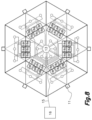
- the central module can include an array of six unitary modules defining a hexagonal-shaped central module with six edges, and each secondary module can include an array of three unitary modules defining a trapezial-shaped secondary module. When one of said secondary modules is connected on each of the six edges of the central module a hexagonal platform is created.
- said unitary modules can be squared.
- the central module will include one unitary module or an array of unitary modules defining a square or rectangular central module with four edges
- each secondary module will include an array of unitary modules defining a square or rectangular secondary module, the combination of the central module and the secondary modules defining a square, rectangular or cross-shaped platform.
- the central module can be a squared central module defined by four unitary modules, and each secondary module can include an array of three unitary modules in line which, when connected to all the edges of the central module produce a squared platform.
- the secondary modules can be a rectangular secondary module including six unitary modules arranged in two rows, producing a bigger squared platform when attached to the central module.
- the design or geometry of the unitary modules used to obtain the central module and the unitary modules used for the secondary modules may or may not be the same.
- the shapes or geometries obtained as a result of the combination of two or more unitary modules, which are regular polygons does not have to meet with these requirements, and therefore the shape or geometry of either the central module or the secondary modules or both, do not necessarily have to form a regular polygon and therefore such a combination may enable the obtention of other shapes or geometries, such as convex quadrilaterals (e.g. an isosceles trapezium, rhombus, rectangle, amongst others).
- each one the n-secondary modules which are coupled to one of the n-sides of the central module have a signalling beacon on one of its external sides, said signalling beacon being configured to emit light signals, in a visible spectrum and/or an infrared spectrum, to said transceiver of a UAV.
- said supporting legs are fastened to the central module of the platform and comprises adjustable supporting legs with an adjustable length, including an extension-retraction mechanism actuated by an associated motor.
- Said extension-retraction mechanism can be for example a telescopic mechanism.
- the control unit can be connected with an inclination sensor attached to the platform and can be configured to control the associated motors of the adjustable supporting legs to automatically level the platform horizontally.
- the unitary modules integrated in the central module or in the same secondary module are detachably connected to each other through structural sockets, electric sockets or through structural sockets, electric sockets and signal sockets, allowing for a complete disassembly of the platform and the easy and fast substitution of any particular unitary module.
- the unitary modules used are in the shape of squares, and both the central module and the secondary modules used are regular polygons.
- the platform actually uses four secondary modules in order to provide a flat continuous quadrangular landing surface, wherein each one of the secondary modules is made up of two unitary modules, with one unitary module coupled to one of the sides of the central module, and the other unitary module being adjacent to a vertex of the central module, laterally coupled to the other unitary module of the same secondary module.
- the unitary modules used are in the shape of equilateral triangles, and the central module is a regular polygon whilst the secondary modules are not.
- the secondary modules are in the shape of an isosceles trapezium, each one consisting of three unitary modules coupled together, wherein the smaller side of each secondary module is coupled to a respective side of the central module.
- references to geometric position such as parallel, perpendicular, tangent, etc. allow deviations up to ⁇ 5° from the theoretical position defined by this nomenclature.
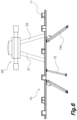
- the exemplary landing platform 10 includes supporting legs 12 fastened to the platform and having a fixed length and two additional adjustable supporting legs 12a adjustable in length by an extension-retraction mechanism, for example including a telescopic feature, actuated by associated motors 17.
- an extension-retraction mechanism for example including a telescopic feature
- Such motors can be automatically controlled by a control unit 13 connected to an inclination sensor attached to the platform to level de platform horizontally.
- the landing platform provides an electrical charging system for an UAV equipped with a base with several downward conductive projections landed thereon.
- Said electrical charging system comprises a plurality of coplanar adjacent electroconductive plates 14, with their adjacent or neighbouring edges electrically insulated, the plates 14 being arranged on an electrically insulated support (for example embedded in it), and with each electroconductive plate 14 being connected with one electroconductive cable 15 to a power source 16 to provide electrical connection and being able to provide electrical energy to said electroconductive plates 14.
- Each electroconductive plate 14 is monitored and electrically controlled by a control unit 13.
- said monitoring of the electroconductive plates 14 is produced by one or multiple detectors of changes in the magnetic fields induced on each conductive cable connected to the control unit 13, said detectors facing or surrounding said conductive cables 15.
- the control unit 13 can be connected to one or multiple detectors of changes in the potential and/or current of each conductive cable 15, said detectors being in electric contact with each conductive cable 15.
- Many other potential and/or current detection configurations are also possible.
- the control unit 13 also control the delivery of electric energy from the power source 16 to each electroconductive plate 14.
- Said control unit 13 can be for example a programable logic controller, a microcontroller, a computer or other programable electronic device.
- Any electroconductive plate 14 can be associated with any other electroconductive plate 14 forming a pair of electroconductive plates 14.
- Power source 16 can be installed near the landing platform 10 or at a distance thereof.
- the control unit 13 is configured to at least:
- the control unit 13 is further configured to perform operations to control the state of charge and electrical conditions of the UAV once the UAV has landed on the platform using said electroconductive cables 15 (one for each of the plates 14).
- the landing platform as can be seen considering Figs. 1 and 4 is made up of a plurality of unitary modules coupled together, with each unitary module comprising an electroconductive plate 14, said unitary modules being adjacent and coplanar to one another.
- the proposed platform 10 as shown in specific embodiments in Fig. 3-8 , comprises:
- the landing platform 10 comprises
- each of the n-edges of the central module includes a central electric socket 18a and a central structural socket 18c, to establish an electrical and structural connection with a corresponding secondary electric socket 18b and secondary structural socket 18d of an edge of an adjacent secondary module 10b.
- the central module receives on the underside a number of electroconductive cables 15 one per each of the electro conductive plates 14 of the central module 10a (or one cable 15, distributed to the other electro conductive plates 14 of the central modules 10a), and the other remaining secondary electroconductive plates 14 are connected to the central module 10a via electroconductive cables 15a connected to the peripheral central electric sockets 18a of the n-edges of the central module 10a.
- each one of the central module electroconductive plates 14 is electrically connected by a corresponding electroconductive cable 15 and the other electroconductive plates 14 of the secondary modules 10b surrounding the central module 10a receive the electrical connection by a corresponding cable 15a via one of the mentioned secondary and central electric sockets 18a and 18b connected each other on the adjacent edges.
- the secondary modules 10b are keep in place in regard with the central module 10a and are supported on said central module 10a through the mentioned secondary and central structural sockets 18c and 18d connected each other on the adjacent edges.
- the supporting legs 12 are fastened to the central module 10a and the secondary modules 10b are supported on the central module 10a in cantilever through said connection between the central and secondary structural sockets 18c and 18d.
- Said central and secondary structural sockets 18c and 18d can be for example complementary clamping configurations which, once coupled, can transmit structural loads therethrough, said central structural socket 18c being integrated in a base structure of the central module 10a and the secondary structural socket 18d being integrated in a base structure of the secondary modules 10b, and the connection between the central and secondary structural sockets 18c and 18d stablishing a structural continuity between said base structures.
- Said central and secondary structural sockets 18c and 18d can include complementary pins and holes, lugs and dowels, dovetail connections, releasable clips, and many other.
- the control unit 13 is directly connected with each electroconductive plate 14 of the platform through a cable.
- the electroconductive plates 14 of the central module 10a are directly connected to the control unit 13, which is preferably integrated on said central module, and the central module further comprise, on each edge, a central signal socket 18e connected with the control unit 13 through a cable,
- the electroconductive plates 14 of each secondary modules 10b are connected to a secondary signal socket 18f which connects said electroconductive plates 14 with the control module 13 through the connection between the central and secondary signal sockets 18e and 18f, allowing the control unit 13 to detect when a pair of electroconductive plates 14 suffer a change in the potential and/or current for the landing of a UAV thereon.
- control unit 13 can communicate with said UAV to determine the need of a recharge and can control the delivery of electric energy to said pair of electroconductive plates 14 from the power source 16.
- control unit 13 When the control unit 13 communicates with said UAV to recharge the UAV, previously to recharge, the control unit 13 and the UAV exchanges each other electrical internal information so that they can be electrically coupled.
- the information inter-changed is related to electrical connections characteristics, for example if the UAV is able to charge without taking into account the polarity of the powered potential on its legs 21-22, the amount of current, voltage and/or power that the UAV is able to manage, and other communication and/or electrical parameters to ensure a safe electrical interconnection for charging or maintenance operations.
- the power source 16 can be a transportable battery, a transportable generator, a connection to the grid or other alternatives.
- Fig. 4 the set of cables 15 have been indicated as single hose containing them by way of example.
- each of said n-secondary modules have a signalling beacon (11) at an external side configured to emit light signals to a UAV in a visible spectrum and/or an infrared spectrum.
- This light signal could be from any other part of the spectrum, e.g. UV.
- the insulation of the adjacent edges of the electroconductive plates 14 is obtained by means of a dielectric sheet 19 or profile arranged between the adjacent edges.
- this cable 15 may contain two separate and different lines, one for potential and/or current detection and the other for electrical power supply.
Landscapes
- Engineering & Computer Science (AREA)
- Aviation & Aerospace Engineering (AREA)
- Transportation (AREA)
- Power Engineering (AREA)
- Mechanical Engineering (AREA)
- Remote Sensing (AREA)
- Chemical & Material Sciences (AREA)
- Combustion & Propulsion (AREA)
- Life Sciences & Earth Sciences (AREA)
- Sustainable Development (AREA)
- Sustainable Energy (AREA)
- Charge And Discharge Circuits For Batteries Or The Like (AREA)
Claims (15)
- Landeplattform für unbemannte Luftfahrzeuge, UAV, die ein elektrisches Ladesystem aufweist, wobei die Plattform (10) Folgendes umfasst:- eine Vielzahl von Stützbeinen (12), die an einer Unterseite der Plattform (10) befestigt sind, und- eine Vielzahl koplanarer benachbarter elektrisch leitender Platten (14), deren benachbarte Kanten elektrisch isoliert sind, wobei die elektrisch leitenden Platten (14) auf einem elektrisch isolierten Träger angeordnet sind, wobei jede elektrisch leitende Platte (14) mit mindestens einem elektrisch leitenden Kabel mit einer Stromquelle (16) verbunden ist und von einer Kontrolleinheit (13) überwacht wird, wobei Paare elektrisch leitender Platten (14) einen Stromkreis definieren; wobeidie Kontrolleinheit (13) ausgebildet ist, um mindestens:eine Veränderung eines elektrischen Potentials und/oder Stroms des Stromkreises aufgrund der Landung eines UAV auf der Plattform zu erkennen und mindestens zwei Kontaktpunkte bereitzustellen, indem das UAV mit mindestens zwei verschiedenen elektrisch leitenden Platten (14) in elektrischen Kontakt gebracht wird, undEnergie von der Stromquelle zu den mindestens zwei elektrisch leitenden Platten (14) unter Verwendung des mindestens einen entsprechenden elektrisch leitenden Kabels von jeder der zwei verschiedenen elektrisch leitenden Platten (14) zuzuführen, um die Stromversorgungsmittel des UAV aufzuladen;dadurch gekennzeichnet, dass die Plattform Folgendes umfasst:ein zentrales Modul (10a), das aus mindestens einem Einheitsmodul besteht, das eine der elektrisch leitenden Platten (14) umfasst, wobei das zentrale Modul (10a) n-Kanten aufweist und zentrale Strukturbuchsen (18c) und zentrale elektrische Buchsen (18a) an mindestens einigen der n-Kanten einschließt, wobei jede der zentralen elektrischen Buchsen (18a) über ein elektrisch leitendes Kabel (15) mit der Stromquelle (16) verbunden ist,mehrere sekundäre Module (10b), die jeweils aus mindestens einem Einheitsmodul bestehen, das eine der elektrisch leitenden Platten (14) umfasst, wobei jedes sekundäre Modul (10b) eine Kante mit einer sekundären Strukturbuchse (18d) und mit einer sekundären elektrischen Buchse (18b) aufweist, die über ein elektrisches Kabel (15a) mit allen Einheitsmodulen, die in dem sekundären Modul (10b) enthalten sind, elektrisch verbunden ist, wobei die sekundäre elektrische Buchse (18b) abnehmbar mit einer der zentralen elektrischen Buchsen (18a) verbunden ist und die sekundäre Strukturbuchse (18d) abnehmbar mit einer der zentralen Strukturbuchsen (18c) verbunden ist, die die sekundären Module (10b) freitragend tragen.
- Landeplattform nach Anspruch 1, wobei die Kontrolleinheit (13) ferner so ausgebildet ist, dass sie Vorgänge zur Kontrolle des Ladezustands und der elektrischen Bedingungen des UAV durchführt, sobald das UAV auf der Plattform gelandet ist.
- Landeplattform nach Anspruch 1 oder 2, wobei jede der n-Kanten des zentralen Moduls ein daran befestigtes sekundäres Modul aufweist.
- Landeplattform nach einem der vorhergehenden Ansprüche, wobei die Kontrolleinheit (13) unterhalb des zentralen Moduls angebracht ist und/oder die Stützbeine (12) klappbar oder vom zentralen Modul abnehmbar sind.
- Landeplattform nach einem der vorhergehenden Ansprüche, wobei• jede elektrisch leitende Platte (14) des zentralen Moduls über ein Signalkabel mit der Kontrolleinheit (13) verbunden ist;• die Kanten des zentralen Moduls (10a), die mit zentralen Strukturbuchsen (18c) und zentralen elektrischen Buchsen (18a) bereitgestellt sind, ferner zentrale Signalbuchsen (18e) umfassen, die über ein Signalkabel mit der Kontrolleinheit (13) verbunden sind;• die Kanten der sekundären Module (10b), die mit sekundären Strukturbuchsen (18d) und sekundären elektrischen Buchsen (18b) bereitgestellt sind, ferner sekundäre Signalbuchsen (18f) umfassen, die abnehmbar mit den zentralen Signalbuchsen (18e) verbunden sind, wobei jede elektrisch leitende Platte (14) der sekundären Module (10b) über ein Signalkabel mit einer sekundären Signalbuchse (18f) verbunden ist.
- Landeplattform nach einem der vorhergehenden Ansprüche 1 bis 4, wobei die Kontrolleinheit (13) so ausgebildet ist, dass sie den Potential- und/oder Stromzustand von Paaren leitender Kabel (15 oder 15a) überwacht, die die Stromquelle (16) mit den elektrisch leitenden Platten (14) verbinden.
- Landeplattform nach einem der vorhergehenden Ansprüche, wobei die Einheitsmodule regelmäßige Polygone sind.
- Landeplattform nach einem der vorhergehenden Ansprüche 1 bis 6, wobeidie Einheitsmodule gleichseitige Dreiecke sind, das zentrale Modul ein Einheitsmodul oder eine Anordnung von Einheitsmodulen einschließt, die ein dreieckiges zentrales Modul mit drei Kanten oder ein sechseckiges zentrales Modul mit sechs Kanten definieren, und jedes sekundäre Modul ein Einheitsmodul oder eine Anordnung von Einheitsmodulen einschließt, die ein dreieckiges oder trapezförmiges sekundäres Modul definieren, wobei die Kombination aus dem zentralen Modul und den sekundären Modulen eine dreieckige oder sechseckige Plattform definiert; oderdie Einheitsmodule quadratisch sind, das zentrale Modul ein Einheitsmodul oder eine Anordnung von Einheitsmodulen einschließt, die ein quadratisches oder rechteckiges zentrales Modul mit vier Kanten definieren, und jedes sekundäre Modul eine Anordnung von Einheitsmodulen einschließt, die ein quadratisches oder rechteckiges sekundäres Modul definieren, wobei die Kombination des zentralen Moduls und der sekundären Module eine quadratische, rechteckige oder kreuzförmige Plattform definieren.
- Landeplattform nach einem der vorhergehenden Ansprüche, wobeidie Vielzahl von Stützbeinen (12) an dem zentralen Modul der Plattform (10) befestigt ist; und/oderdie Vielzahl von Stützbeinen (12) einstellbare Stützbeine (12a) mit einer einstellbaren Länge umfasst.
- Landeplattform nach Anspruch 9, wobei die einstellbaren Stützbeine (12a) einen Ausfahr-Einfahr-Mechanismus einschließen, der durch einen verknüpften Motor (17) betätigt wird.
- Landeplattform nach Anspruch 10, wobei die Kontrolleinheit (13) mit einem Neigungssensor verbunden ist, der an der Plattform angebracht ist, und so ausgebildet ist, dass sie die zugehörigen Motoren (17) der einstellbaren Stützbeine (12a) kontrolliert, um die Plattform horizontal zu nivellieren.
- Landeplattform nach einem der vorhergehenden Ansprüche, wobei die Plattform mehrere Signalbaken (11) an externen Kanten davon aufweist, die so ausgebildet sind, dass sie Lichtsignale an ein UAV in mindestens einem sichtbaren Spektrum und/oder einem Infrarotspektrum emittieren.
- Landeplattform nach einem der vorhergehenden Ansprüche, wobei die benachbarten Kanten der elektrisch leitenden Platten (14) mittels einer zwischen den benachbarten Kanten angeordneten dielektrischen Folie (19) elektrisch isoliert sind.
- Landeplattform nach Anspruch 5, wobei die in das zentrale Modul oder in dasselbe sekundäre Modul integrierten Einheitsmodule über Strukturbuchsen und elektrischen Buchsen oder über Strukturbuchsen und elektrischen Buchsen und Signalbuchsen abnehmbar miteinander verbunden sind.
- Landeplattform nach Anspruch 5, wobei die Gruppe der zentralen elektrischen Buchsen (18a), die mit den sekundären elektrischen Buchsen (18b) gekoppelt sind, und die Gruppe der zentralen Signalbuchsen (18e), die mit den sekundären Signalbuchsen (18f) gekoppelt sind, in einer einzigen Buchsengruppe integriert sind.
Applications Claiming Priority (2)
| Application Number | Priority Date | Filing Date | Title |
|---|---|---|---|
| EP19382391.1A EP3738891A1 (de) | 2019-05-17 | 2019-05-17 | Landeplattform für unbemannte luftfahrzeuge |
| PCT/EP2020/063680 WO2020234177A1 (en) | 2019-05-17 | 2020-05-15 | Landing platform for unmanned aerial vehicles |
Publications (3)
| Publication Number | Publication Date |
|---|---|
| EP3969372A1 EP3969372A1 (de) | 2022-03-23 |
| EP3969372C0 EP3969372C0 (de) | 2023-07-05 |
| EP3969372B1 true EP3969372B1 (de) | 2023-07-05 |
Family
ID=66625903
Family Applications (2)
| Application Number | Title | Priority Date | Filing Date |
|---|---|---|---|
| EP19382391.1A Withdrawn EP3738891A1 (de) | 2019-05-17 | 2019-05-17 | Landeplattform für unbemannte luftfahrzeuge |
| EP20726790.7A Active EP3969372B1 (de) | 2019-05-17 | 2020-05-15 | Landeplattform für unbemannte luftfahrzeuge |
Family Applications Before (1)
| Application Number | Title | Priority Date | Filing Date |
|---|---|---|---|
| EP19382391.1A Withdrawn EP3738891A1 (de) | 2019-05-17 | 2019-05-17 | Landeplattform für unbemannte luftfahrzeuge |
Country Status (4)
| Country | Link |
|---|---|
| US (1) | US12208697B2 (de) |
| EP (2) | EP3738891A1 (de) |
| ES (1) | ES2956269T3 (de) |
| WO (1) | WO2020234177A1 (de) |
Families Citing this family (15)
| Publication number | Priority date | Publication date | Assignee | Title |
|---|---|---|---|---|
| CA3191056A1 (en) * | 2020-05-18 | 2021-11-25 | Chirag Shah | Method and system to ascertain location of drone box for landing and charging drones |
| EP4139763B1 (de) * | 2021-02-01 | 2024-09-25 | Sagar Defence Engineering Private Limited | Verfahren und system zur bestimmung der position eines drohnenkastens für stabilisierte landung und vergebührung einer drohne |
| WO2023060326A1 (pt) * | 2021-10-11 | 2023-04-20 | Goncalves Dos Santos Junior Anisio | Disposição aplicada em plataforma com auto-nivelamento para pousos e decolagens de veículo aéreo não tripulado |
| WO2023162405A1 (ja) * | 2022-02-22 | 2023-08-31 | 日本国土開発株式会社 | 移動装置および無人飛行装置 |
| EP4293866A1 (de) * | 2022-06-16 | 2023-12-20 | GEOSTAT Aerospace & Technology Inc. | Vorrichtungen und verfahren zum bereitstellen von ladeleistung für ein externes gerät |
| CN115723982B (zh) * | 2022-11-14 | 2023-07-07 | 众芯汉创(北京)科技有限公司 | 一种适用于寒冷地区的无人机便携式充电补给装置 |
| KR102814864B1 (ko) * | 2022-12-08 | 2025-05-30 | 한국항공우주연구원 | 이착륙 성능개선 시스템 |
| TWI882361B (zh) * | 2023-06-15 | 2025-05-01 | 經緯航太科技股份有限公司 | 對外部設備提供充電功率的裝置和方法 |
| MX2024010921A (es) * | 2023-09-11 | 2025-04-02 | Polaris Inc | Integracion de dron con el vehiculo |
| US12344411B1 (en) * | 2024-04-03 | 2025-07-01 | Hoodman Corporation | Foldable launch and landing pad for drones |
| CN118004475B (zh) * | 2024-04-08 | 2024-06-21 | 国网山东省电力公司泰安供电公司 | 一种用于检测电力故障的巡检无人机平台 |
| US12545447B1 (en) * | 2024-06-07 | 2026-02-10 | Amazon Technologies, Inc. | Aerial vehicle landing pad with sensors |
| US20260048865A1 (en) * | 2024-08-15 | 2026-02-19 | Skydio, Inc. | Method of docking an unmanned aerial vehicle with a base station |
| US20260048877A1 (en) * | 2024-08-15 | 2026-02-19 | Skydio, Inc. | Base Station For An Unmanned Aerial Vehicle Including A Rotatable Roof Assembly |
| CN120621770A (zh) * | 2025-07-29 | 2025-09-12 | 中建三局集团(深圳)有限公司 | 折叠式无人机停机坪及无人机停机坪的使用方法 |
Family Cites Families (15)
| Publication number | Priority date | Publication date | Assignee | Title |
|---|---|---|---|---|
| US7172196B2 (en) * | 2002-12-10 | 2007-02-06 | Mitch Randall | Systems and methods for providing electric power to mobile and arbitrarily positioned devices |
| US7417197B2 (en) * | 2003-09-19 | 2008-08-26 | Medconx, Inc. | Direct contact power transfer pad and method of making same |
| KR101440626B1 (ko) * | 2008-11-06 | 2014-09-15 | 한국과학기술원 | 확장 가능한 원격제어 모바일 유닛 자동 충전 시스템 및 방법 |
| US9701425B2 (en) | 2013-08-23 | 2017-07-11 | Korea Aerospace Research Institute | Apparatus and method of charging and housing of unmanned vertical take-off and landing (VTOL) aircraft |
| EP2858207B1 (de) * | 2013-10-03 | 2018-07-11 | The Boeing Company | Aufladen einer Flugzeugbatterie |
| DE102014100493A1 (de) * | 2014-01-17 | 2015-07-23 | Michele Dallachiesa | Ladevorrichtung und Verfahren zum elektrischen Laden von Batteriezellen |
| US9561871B2 (en) | 2014-05-07 | 2017-02-07 | Deere & Company | UAV docking system and method |
| CN105308820B (zh) * | 2014-06-12 | 2018-06-12 | 深圳市大疆创新科技有限公司 | 一种充电系统、供电装置及飞行器 |
| US10434885B2 (en) | 2014-08-05 | 2019-10-08 | Telecom Italia S.P.A. | Landing platform for an unmanned aerial vehicle |
| WO2016113766A1 (en) * | 2015-01-12 | 2016-07-21 | Sequoia Automation S.R.L. | Electrically charging system for drones |
| KR20170040961A (ko) * | 2015-10-06 | 2017-04-14 | 엘지이노텍 주식회사 | 무인비행체 무선충전 시스템 및 이의 구동 방법 |
| US20180237161A1 (en) * | 2017-02-21 | 2018-08-23 | Echostar Technologies L.L.C. | Systems and methods for uav docking and recharging |
| CN110745252B (zh) | 2018-07-23 | 2024-11-12 | 上海峰飞航空科技有限公司 | 用于无人驾驶飞行器的着陆平台、方法和充电系统 |
| CN109050885A (zh) * | 2018-08-12 | 2018-12-21 | 南京云睿航天科技有限公司 | 一种无人机多点接触充电平板 |
| CN208699068U (zh) * | 2018-09-05 | 2019-04-05 | 浙江海洋大学 | 一种无人机组件 |
-
2019
- 2019-05-17 EP EP19382391.1A patent/EP3738891A1/de not_active Withdrawn
-
2020
- 2020-05-15 ES ES20726790T patent/ES2956269T3/es active Active
- 2020-05-15 WO PCT/EP2020/063680 patent/WO2020234177A1/en not_active Ceased
- 2020-05-15 EP EP20726790.7A patent/EP3969372B1/de active Active
- 2020-05-15 US US17/611,598 patent/US12208697B2/en active Active
Also Published As
| Publication number | Publication date |
|---|---|
| US20220315248A1 (en) | 2022-10-06 |
| WO2020234177A1 (en) | 2020-11-26 |
| US12208697B2 (en) | 2025-01-28 |
| ES2956269T3 (es) | 2023-12-18 |
| EP3969372A1 (de) | 2022-03-23 |
| EP3738891A1 (de) | 2020-11-18 |
| EP3969372C0 (de) | 2023-07-05 |
Similar Documents
| Publication | Publication Date | Title |
|---|---|---|
| EP3969372B1 (de) | Landeplattform für unbemannte luftfahrzeuge | |
| US11643205B2 (en) | Systems and methods for charging, transporting, and operating flying machines | |
| US11811224B2 (en) | Distributed-battery aerial vehicle and a powering method therefor | |
| KR101720028B1 (ko) | 무인항공기의 무선충전장치 | |
| EP3347276B1 (de) | Drohnenfluggerätlande- und andocksysteme | |
| JP5874940B1 (ja) | 飛行体、及びバッテリユニット収納システム | |
| KR101571161B1 (ko) | 무인 항공기, 충전 스테이션 및 이를 포함하는 무인 항공기 자동 충전 시스템 | |
| US20190233100A1 (en) | Reconfigurable battery-operated vehicle system | |
| KR20130109986A (ko) | 재구성가능한 배터리-작동식 운행체 시스템 | |
| CN106715265A (zh) | 无人飞行器起降平台 | |
| CA3149568A1 (en) | Uav airways systems and apparatus | |
| EP3095170A1 (de) | Ladevorrichtung und verfahren zum elektrischen laden von energiespeichervorrichtungen | |
| EP3804082A1 (de) | Stromversorgung von uav in der nähe von stromleitungen | |
| KR20160015714A (ko) | 무인 비행체, 이의 충전 시스템 및 이의 충전 방법 | |
| Conyers | A mobile self-leveling landing platform for small-scale uavs | |
| JP7076785B2 (ja) | ドローン充電システム | |
| WO2025261733A1 (en) | Interchangeable external battery, battery fastening module for a rotor-powered drone and system for fastening an interchangeable external battery | |
| HK40002254A (en) | Systems and methods for charging, transporting, and operating flying machines |
Legal Events
| Date | Code | Title | Description |
|---|---|---|---|
| STAA | Information on the status of an ep patent application or granted ep patent |
Free format text: STATUS: UNKNOWN |
|
| STAA | Information on the status of an ep patent application or granted ep patent |
Free format text: STATUS: THE INTERNATIONAL PUBLICATION HAS BEEN MADE |
|
| PUAI | Public reference made under article 153(3) epc to a published international application that has entered the european phase |
Free format text: ORIGINAL CODE: 0009012 |
|
| STAA | Information on the status of an ep patent application or granted ep patent |
Free format text: STATUS: REQUEST FOR EXAMINATION WAS MADE |
|
| 17P | Request for examination filed |
Effective date: 20211104 |
|
| AK | Designated contracting states |
Kind code of ref document: A1 Designated state(s): AL AT BE BG CH CY CZ DE DK EE ES FI FR GB GR HR HU IE IS IT LI LT LU LV MC MK MT NL NO PL PT RO RS SE SI SK SM TR |
|
| DAV | Request for validation of the european patent (deleted) | ||
| DAX | Request for extension of the european patent (deleted) | ||
| GRAP | Despatch of communication of intention to grant a patent |
Free format text: ORIGINAL CODE: EPIDOSNIGR1 |
|
| STAA | Information on the status of an ep patent application or granted ep patent |
Free format text: STATUS: GRANT OF PATENT IS INTENDED |
|
| INTG | Intention to grant announced |
Effective date: 20230102 |
|
| GRAS | Grant fee paid |
Free format text: ORIGINAL CODE: EPIDOSNIGR3 |
|
| GRAA | (expected) grant |
Free format text: ORIGINAL CODE: 0009210 |
|
| STAA | Information on the status of an ep patent application or granted ep patent |
Free format text: STATUS: THE PATENT HAS BEEN GRANTED |
|
| AK | Designated contracting states |
Kind code of ref document: B1 Designated state(s): AL AT BE BG CH CY CZ DE DK EE ES FI FR GB GR HR HU IE IS IT LI LT LU LV MC MK MT NL NO PL PT RO RS SE SI SK SM TR |
|
| REG | Reference to a national code |
Ref country code: CH Ref legal event code: EP |
|
| REG | Reference to a national code |
Ref country code: AT Ref legal event code: REF Ref document number: 1584643 Country of ref document: AT Kind code of ref document: T Effective date: 20230715 |
|
| REG | Reference to a national code |
Ref country code: DE Ref legal event code: R096 Ref document number: 602020013342 Country of ref document: DE |
|
| REG | Reference to a national code |
Ref country code: IE Ref legal event code: FG4D |
|
| U01 | Request for unitary effect filed |
Effective date: 20230711 |
|
| U07 | Unitary effect registered |
Designated state(s): AT BE BG DE DK EE FI FR IT LT LU LV MT NL PT SE SI Effective date: 20230724 |
|
| REG | Reference to a national code |
Ref country code: LT Ref legal event code: MG9D |
|
| REG | Reference to a national code |
Ref country code: ES Ref legal event code: FG2A Ref document number: 2956269 Country of ref document: ES Kind code of ref document: T3 Effective date: 20231218 |
|
| PG25 | Lapsed in a contracting state [announced via postgrant information from national office to epo] |
Ref country code: GR Free format text: LAPSE BECAUSE OF FAILURE TO SUBMIT A TRANSLATION OF THE DESCRIPTION OR TO PAY THE FEE WITHIN THE PRESCRIBED TIME-LIMIT Effective date: 20231006 |
|
| PG25 | Lapsed in a contracting state [announced via postgrant information from national office to epo] |
Ref country code: IS Free format text: LAPSE BECAUSE OF FAILURE TO SUBMIT A TRANSLATION OF THE DESCRIPTION OR TO PAY THE FEE WITHIN THE PRESCRIBED TIME-LIMIT Effective date: 20231105 |
|
| PG25 | Lapsed in a contracting state [announced via postgrant information from national office to epo] |
Ref country code: RS Free format text: LAPSE BECAUSE OF FAILURE TO SUBMIT A TRANSLATION OF THE DESCRIPTION OR TO PAY THE FEE WITHIN THE PRESCRIBED TIME-LIMIT Effective date: 20230705 Ref country code: NO Free format text: LAPSE BECAUSE OF FAILURE TO SUBMIT A TRANSLATION OF THE DESCRIPTION OR TO PAY THE FEE WITHIN THE PRESCRIBED TIME-LIMIT Effective date: 20231005 Ref country code: IS Free format text: LAPSE BECAUSE OF FAILURE TO SUBMIT A TRANSLATION OF THE DESCRIPTION OR TO PAY THE FEE WITHIN THE PRESCRIBED TIME-LIMIT Effective date: 20231105 Ref country code: HR Free format text: LAPSE BECAUSE OF FAILURE TO SUBMIT A TRANSLATION OF THE DESCRIPTION OR TO PAY THE FEE WITHIN THE PRESCRIBED TIME-LIMIT Effective date: 20230705 Ref country code: GR Free format text: LAPSE BECAUSE OF FAILURE TO SUBMIT A TRANSLATION OF THE DESCRIPTION OR TO PAY THE FEE WITHIN THE PRESCRIBED TIME-LIMIT Effective date: 20231006 |
|
| PG25 | Lapsed in a contracting state [announced via postgrant information from national office to epo] |
Ref country code: PL Free format text: LAPSE BECAUSE OF FAILURE TO SUBMIT A TRANSLATION OF THE DESCRIPTION OR TO PAY THE FEE WITHIN THE PRESCRIBED TIME-LIMIT Effective date: 20230705 |
|
| REG | Reference to a national code |
Ref country code: DE Ref legal event code: R097 Ref document number: 602020013342 Country of ref document: DE |
|
| PG25 | Lapsed in a contracting state [announced via postgrant information from national office to epo] |
Ref country code: SM Free format text: LAPSE BECAUSE OF FAILURE TO SUBMIT A TRANSLATION OF THE DESCRIPTION OR TO PAY THE FEE WITHIN THE PRESCRIBED TIME-LIMIT Effective date: 20230705 Ref country code: RO Free format text: LAPSE BECAUSE OF FAILURE TO SUBMIT A TRANSLATION OF THE DESCRIPTION OR TO PAY THE FEE WITHIN THE PRESCRIBED TIME-LIMIT Effective date: 20230705 Ref country code: CZ Free format text: LAPSE BECAUSE OF FAILURE TO SUBMIT A TRANSLATION OF THE DESCRIPTION OR TO PAY THE FEE WITHIN THE PRESCRIBED TIME-LIMIT Effective date: 20230705 Ref country code: SK Free format text: LAPSE BECAUSE OF FAILURE TO SUBMIT A TRANSLATION OF THE DESCRIPTION OR TO PAY THE FEE WITHIN THE PRESCRIBED TIME-LIMIT Effective date: 20230705 |
|
| PLBE | No opposition filed within time limit |
Free format text: ORIGINAL CODE: 0009261 |
|
| STAA | Information on the status of an ep patent application or granted ep patent |
Free format text: STATUS: NO OPPOSITION FILED WITHIN TIME LIMIT |
|
| 26N | No opposition filed |
Effective date: 20240408 |
|
| U20 | Renewal fee for the european patent with unitary effect paid |
Year of fee payment: 5 Effective date: 20240528 |
|
| REG | Reference to a national code |
Ref country code: CH Ref legal event code: PL |
|
| PG25 | Lapsed in a contracting state [announced via postgrant information from national office to epo] |
Ref country code: MC Free format text: LAPSE BECAUSE OF FAILURE TO SUBMIT A TRANSLATION OF THE DESCRIPTION OR TO PAY THE FEE WITHIN THE PRESCRIBED TIME-LIMIT Effective date: 20230705 |
|
| GBPC | Gb: european patent ceased through non-payment of renewal fee |
Effective date: 20240515 |
|
| PG25 | Lapsed in a contracting state [announced via postgrant information from national office to epo] |
Ref country code: MC Free format text: LAPSE BECAUSE OF FAILURE TO SUBMIT A TRANSLATION OF THE DESCRIPTION OR TO PAY THE FEE WITHIN THE PRESCRIBED TIME-LIMIT Effective date: 20230705 Ref country code: CH Free format text: LAPSE BECAUSE OF NON-PAYMENT OF DUE FEES Effective date: 20240531 |
|
| PG25 | Lapsed in a contracting state [announced via postgrant information from national office to epo] |
Ref country code: IE Free format text: LAPSE BECAUSE OF NON-PAYMENT OF DUE FEES Effective date: 20240515 |
|
| PG25 | Lapsed in a contracting state [announced via postgrant information from national office to epo] |
Ref country code: GB Free format text: LAPSE BECAUSE OF NON-PAYMENT OF DUE FEES Effective date: 20240515 |
|
| U20 | Renewal fee for the european patent with unitary effect paid |
Year of fee payment: 6 Effective date: 20250529 |
|
| PGFP | Annual fee paid to national office [announced via postgrant information from national office to epo] |
Ref country code: ES Payment date: 20250612 Year of fee payment: 6 |
|
| PG25 | Lapsed in a contracting state [announced via postgrant information from national office to epo] |
Ref country code: CY Free format text: LAPSE BECAUSE OF FAILURE TO SUBMIT A TRANSLATION OF THE DESCRIPTION OR TO PAY THE FEE WITHIN THE PRESCRIBED TIME-LIMIT; INVALID AB INITIO Effective date: 20200515 |
|
| PG25 | Lapsed in a contracting state [announced via postgrant information from national office to epo] |
Ref country code: HU Free format text: LAPSE BECAUSE OF FAILURE TO SUBMIT A TRANSLATION OF THE DESCRIPTION OR TO PAY THE FEE WITHIN THE PRESCRIBED TIME-LIMIT; INVALID AB INITIO Effective date: 20200515 |