EP3969100B1 - Système de contrôle de fonction autonome - Google Patents
Système de contrôle de fonction autonome Download PDFInfo
- Publication number
- EP3969100B1 EP3969100B1 EP20726109.0A EP20726109A EP3969100B1 EP 3969100 B1 EP3969100 B1 EP 3969100B1 EP 20726109 A EP20726109 A EP 20726109A EP 3969100 B1 EP3969100 B1 EP 3969100B1
- Authority
- EP
- European Patent Office
- Prior art keywords
- blood pressure
- stimulation
- unit
- spinal cord
- lead
- Prior art date
- Legal status (The legal status is an assumption and is not a legal conclusion. Google has not performed a legal analysis and makes no representation as to the accuracy of the status listed.)
- Active
Links
- 230000037424 autonomic function Effects 0.000 title description 7
- 230000000638 stimulation Effects 0.000 claims description 128
- 210000000278 spinal cord Anatomy 0.000 claims description 59
- 238000012544 monitoring process Methods 0.000 claims description 33
- 230000010355 oscillation Effects 0.000 claims description 26
- 238000012545 processing Methods 0.000 claims description 26
- 241000124008 Mammalia Species 0.000 claims description 19
- 230000004007 neuromodulation Effects 0.000 claims description 18
- 230000029865 regulation of blood pressure Effects 0.000 claims 1
- 230000036772 blood pressure Effects 0.000 description 135
- 208000020431 spinal cord injury Diseases 0.000 description 36
- 238000000034 method Methods 0.000 description 25
- 230000002889 sympathetic effect Effects 0.000 description 24
- 210000002569 neuron Anatomy 0.000 description 22
- 210000000115 thoracic cavity Anatomy 0.000 description 22
- 230000010412 perfusion Effects 0.000 description 19
- 230000004913 activation Effects 0.000 description 15
- 238000013507 mapping Methods 0.000 description 15
- 230000004044 response Effects 0.000 description 15
- 230000004872 arterial blood pressure Effects 0.000 description 14
- 241000282414 Homo sapiens Species 0.000 description 13
- 230000035488 systolic blood pressure Effects 0.000 description 12
- 230000000574 ganglionic effect Effects 0.000 description 11
- 241000700159 Rattus Species 0.000 description 10
- 210000000609 ganglia Anatomy 0.000 description 10
- 238000006213 oxygenation reaction Methods 0.000 description 10
- 238000010171 animal model Methods 0.000 description 9
- 238000002513 implantation Methods 0.000 description 9
- 210000003932 urinary bladder Anatomy 0.000 description 8
- 230000035487 diastolic blood pressure Effects 0.000 description 7
- 230000006870 function Effects 0.000 description 7
- 206010003840 Autonomic nervous system imbalance Diseases 0.000 description 6
- 238000002591 computed tomography Methods 0.000 description 6
- 230000001276 controlling effect Effects 0.000 description 6
- 230000007423 decrease Effects 0.000 description 6
- 238000011552 rat model Methods 0.000 description 6
- 208000001953 Hypotension Diseases 0.000 description 5
- 208000027418 Wounds and injury Diseases 0.000 description 5
- 230000002567 autonomic effect Effects 0.000 description 5
- 238000009530 blood pressure measurement Methods 0.000 description 5
- 208000014674 injury Diseases 0.000 description 5
- 210000002820 sympathetic nervous system Anatomy 0.000 description 5
- 241000282412 Homo Species 0.000 description 4
- 206010020772 Hypertension Diseases 0.000 description 4
- 238000000692 Student's t-test Methods 0.000 description 4
- 239000008280 blood Substances 0.000 description 4
- 210000004204 blood vessel Anatomy 0.000 description 4
- 230000002526 effect on cardiovascular system Effects 0.000 description 4
- 230000036543 hypotension Effects 0.000 description 4
- 230000036584 pressor response Effects 0.000 description 4
- 238000011002 quantification Methods 0.000 description 4
- 210000005262 rostral ventrolateral medulla Anatomy 0.000 description 4
- 238000012353 t test Methods 0.000 description 4
- 210000001519 tissue Anatomy 0.000 description 4
- 241000699670 Mus sp. Species 0.000 description 3
- 230000001154 acute effect Effects 0.000 description 3
- 230000002457 bidirectional effect Effects 0.000 description 3
- 230000003592 biomimetic effect Effects 0.000 description 3
- 210000004369 blood Anatomy 0.000 description 3
- 230000000747 cardiac effect Effects 0.000 description 3
- 210000001175 cerebrospinal fluid Anatomy 0.000 description 3
- 230000001684 chronic effect Effects 0.000 description 3
- 230000006378 damage Effects 0.000 description 3
- 238000013461 design Methods 0.000 description 3
- 230000003205 diastolic effect Effects 0.000 description 3
- 210000001153 interneuron Anatomy 0.000 description 3
- 238000002595 magnetic resonance imaging Methods 0.000 description 3
- 239000003550 marker Substances 0.000 description 3
- 210000005036 nerve Anatomy 0.000 description 3
- 230000000926 neurological effect Effects 0.000 description 3
- 230000002746 orthostatic effect Effects 0.000 description 3
- 230000009960 sympathetic pathway Effects 0.000 description 3
- 206010061666 Autonomic neuropathy Diseases 0.000 description 2
- 241000282693 Cercopithecidae Species 0.000 description 2
- 241001465754 Metazoa Species 0.000 description 2
- 206010028980 Neoplasm Diseases 0.000 description 2
- 208000018262 Peripheral vascular disease Diseases 0.000 description 2
- 206010046543 Urinary incontinence Diseases 0.000 description 2
- 210000001015 abdomen Anatomy 0.000 description 2
- 230000036982 action potential Effects 0.000 description 2
- 230000003213 activating effect Effects 0.000 description 2
- 238000013459 approach Methods 0.000 description 2
- 208000008559 autonomic dysreflexia Diseases 0.000 description 2
- 230000017531 blood circulation Effects 0.000 description 2
- 230000008081 blood perfusion Effects 0.000 description 2
- 201000011510 cancer Diseases 0.000 description 2
- 210000003169 central nervous system Anatomy 0.000 description 2
- 238000011161 development Methods 0.000 description 2
- 238000010586 diagram Methods 0.000 description 2
- 210000003414 extremity Anatomy 0.000 description 2
- 230000036541 health Effects 0.000 description 2
- 230000000004 hemodynamic effect Effects 0.000 description 2
- 230000000302 ischemic effect Effects 0.000 description 2
- 238000005259 measurement Methods 0.000 description 2
- 230000007246 mechanism Effects 0.000 description 2
- 201000006417 multiple sclerosis Diseases 0.000 description 2
- 208000010125 myocardial infarction Diseases 0.000 description 2
- 210000000653 nervous system Anatomy 0.000 description 2
- 230000001537 neural effect Effects 0.000 description 2
- 230000003287 optical effect Effects 0.000 description 2
- 210000000578 peripheral nerve Anatomy 0.000 description 2
- 210000003594 spinal ganglia Anatomy 0.000 description 2
- 238000002560 therapeutic procedure Methods 0.000 description 2
- 210000000707 wrist Anatomy 0.000 description 2
- 206010005746 Blood pressure fluctuation Diseases 0.000 description 1
- 108700002232 Immediate-Early Genes Proteins 0.000 description 1
- 208000001089 Multiple system atrophy Diseases 0.000 description 1
- 206010031127 Orthostatic hypotension Diseases 0.000 description 1
- 102100027584 Protein c-Fos Human genes 0.000 description 1
- 101710090875 Protein c-Fos Proteins 0.000 description 1
- 241000283984 Rodentia Species 0.000 description 1
- 206010040030 Sensory loss Diseases 0.000 description 1
- 101150077427 Slc17a6 gene Proteins 0.000 description 1
- 108091000117 Tyrosine 3-Monooxygenase Proteins 0.000 description 1
- 102000048218 Tyrosine 3-monooxygenases Human genes 0.000 description 1
- 208000003443 Unconsciousness Diseases 0.000 description 1
- 238000002679 ablation Methods 0.000 description 1
- 230000001919 adrenal effect Effects 0.000 description 1
- 210000001367 artery Anatomy 0.000 description 1
- 210000003403 autonomic nervous system Anatomy 0.000 description 1
- 230000008901 benefit Effects 0.000 description 1
- 230000000443 biocontrol Effects 0.000 description 1
- 230000004706 cardiovascular dysfunction Effects 0.000 description 1
- 230000009084 cardiovascular function Effects 0.000 description 1
- 210000001326 carotid sinus Anatomy 0.000 description 1
- 239000013043 chemical agent Substances 0.000 description 1
- 230000009693 chronic damage Effects 0.000 description 1
- 230000027288 circadian rhythm Effects 0.000 description 1
- 230000001149 cognitive effect Effects 0.000 description 1
- 238000010402 computational modelling Methods 0.000 description 1
- 230000008602 contraction Effects 0.000 description 1
- 238000000354 decomposition reaction Methods 0.000 description 1
- 230000029087 digestion Effects 0.000 description 1
- 230000001079 digestive effect Effects 0.000 description 1
- 208000037265 diseases, disorders, signs and symptoms Diseases 0.000 description 1
- 208000035475 disorder Diseases 0.000 description 1
- 238000002224 dissection Methods 0.000 description 1
- 208000002173 dizziness Diseases 0.000 description 1
- 239000003814 drug Substances 0.000 description 1
- 230000004064 dysfunction Effects 0.000 description 1
- 230000000694 effects Effects 0.000 description 1
- 230000002964 excitative effect Effects 0.000 description 1
- 238000002474 experimental method Methods 0.000 description 1
- 208000013403 hyperactivity Diseases 0.000 description 1
- 230000001631 hypertensive effect Effects 0.000 description 1
- 238000003384 imaging method Methods 0.000 description 1
- 238000003364 immunohistochemistry Methods 0.000 description 1
- 230000001771 impaired effect Effects 0.000 description 1
- 239000007943 implant Substances 0.000 description 1
- 230000002401 inhibitory effect Effects 0.000 description 1
- 238000007913 intrathecal administration Methods 0.000 description 1
- 208000017169 kidney disease Diseases 0.000 description 1
- 208000012866 low blood pressure Diseases 0.000 description 1
- 238000012423 maintenance Methods 0.000 description 1
- 230000028161 membrane depolarization Effects 0.000 description 1
- QSHDDOUJBYECFT-UHFFFAOYSA-N mercury Chemical compound [Hg] QSHDDOUJBYECFT-UHFFFAOYSA-N 0.000 description 1
- 229910052753 mercury Inorganic materials 0.000 description 1
- 230000027939 micturition Effects 0.000 description 1
- 230000003278 mimic effect Effects 0.000 description 1
- 230000007383 nerve stimulation Effects 0.000 description 1
- 239000002858 neurotransmitter agent Substances 0.000 description 1
- 210000000056 organ Anatomy 0.000 description 1
- 239000002831 pharmacologic agent Substances 0.000 description 1
- IENZQIKPVFGBNW-UHFFFAOYSA-N prazosin Chemical compound N=1C(N)=C2C=C(OC)C(OC)=CC2=NC=1N(CC1)CCN1C(=O)C1=CC=CO1 IENZQIKPVFGBNW-UHFFFAOYSA-N 0.000 description 1
- 229960001289 prazosin Drugs 0.000 description 1
- 230000000272 proprioceptive effect Effects 0.000 description 1
- 230000009467 reduction Effects 0.000 description 1
- 230000001105 regulatory effect Effects 0.000 description 1
- 230000033764 rhythmic process Effects 0.000 description 1
- 238000004088 simulation Methods 0.000 description 1
- 241000894007 species Species 0.000 description 1
- 210000000273 spinal nerve root Anatomy 0.000 description 1
- 230000004936 stimulating effect Effects 0.000 description 1
- 210000000701 subdural space Anatomy 0.000 description 1
- 238000011477 surgical intervention Methods 0.000 description 1
- 210000000225 synapse Anatomy 0.000 description 1
- 230000001839 systemic circulation Effects 0.000 description 1
- 230000008685 targeting Effects 0.000 description 1
- 230000003363 transsynaptic effect Effects 0.000 description 1
- 230000002485 urinary effect Effects 0.000 description 1
- 230000002792 vascular Effects 0.000 description 1
- 210000005166 vasculature Anatomy 0.000 description 1
Images


Classifications
-
- A—HUMAN NECESSITIES
- A61—MEDICAL OR VETERINARY SCIENCE; HYGIENE
- A61N—ELECTROTHERAPY; MAGNETOTHERAPY; RADIATION THERAPY; ULTRASOUND THERAPY
- A61N1/00—Electrotherapy; Circuits therefor
- A61N1/02—Details
- A61N1/04—Electrodes
- A61N1/05—Electrodes for implantation or insertion into the body, e.g. heart electrode
- A61N1/0551—Spinal or peripheral nerve electrodes
-
- A—HUMAN NECESSITIES
- A61—MEDICAL OR VETERINARY SCIENCE; HYGIENE
- A61N—ELECTROTHERAPY; MAGNETOTHERAPY; RADIATION THERAPY; ULTRASOUND THERAPY
- A61N1/00—Electrotherapy; Circuits therefor
- A61N1/18—Applying electric currents by contact electrodes
- A61N1/32—Applying electric currents by contact electrodes alternating or intermittent currents
- A61N1/36—Applying electric currents by contact electrodes alternating or intermittent currents for stimulation
- A61N1/36014—External stimulators, e.g. with patch electrodes
- A61N1/3603—Control systems
- A61N1/36031—Control systems using physiological parameters for adjustment
-
- A—HUMAN NECESSITIES
- A61—MEDICAL OR VETERINARY SCIENCE; HYGIENE
- A61N—ELECTROTHERAPY; MAGNETOTHERAPY; RADIATION THERAPY; ULTRASOUND THERAPY
- A61N1/00—Electrotherapy; Circuits therefor
- A61N1/18—Applying electric currents by contact electrodes
- A61N1/32—Applying electric currents by contact electrodes alternating or intermittent currents
- A61N1/36—Applying electric currents by contact electrodes alternating or intermittent currents for stimulation
- A61N1/3605—Implantable neurostimulators for stimulating central or peripheral nerve system
- A61N1/3606—Implantable neurostimulators for stimulating central or peripheral nerve system adapted for a particular treatment
- A61N1/36114—Cardiac control, e.g. by vagal stimulation
- A61N1/36117—Cardiac control, e.g. by vagal stimulation for treating hypertension
-
- A—HUMAN NECESSITIES
- A61—MEDICAL OR VETERINARY SCIENCE; HYGIENE
- A61N—ELECTROTHERAPY; MAGNETOTHERAPY; RADIATION THERAPY; ULTRASOUND THERAPY
- A61N1/00—Electrotherapy; Circuits therefor
- A61N1/18—Applying electric currents by contact electrodes
- A61N1/32—Applying electric currents by contact electrodes alternating or intermittent currents
- A61N1/36—Applying electric currents by contact electrodes alternating or intermittent currents for stimulation
- A61N1/36014—External stimulators, e.g. with patch electrodes
- A61N1/3603—Control systems
- A61N1/36034—Control systems specified by the stimulation parameters
-
- A—HUMAN NECESSITIES
- A61—MEDICAL OR VETERINARY SCIENCE; HYGIENE
- A61N—ELECTROTHERAPY; MAGNETOTHERAPY; RADIATION THERAPY; ULTRASOUND THERAPY
- A61N1/00—Electrotherapy; Circuits therefor
- A61N1/18—Applying electric currents by contact electrodes
- A61N1/32—Applying electric currents by contact electrodes alternating or intermittent currents
- A61N1/36—Applying electric currents by contact electrodes alternating or intermittent currents for stimulation
- A61N1/3605—Implantable neurostimulators for stimulating central or peripheral nerve system
- A61N1/3606—Implantable neurostimulators for stimulating central or peripheral nerve system adapted for a particular treatment
- A61N1/36062—Spinal stimulation
Definitions
- the present invention refers to the field of spinal cord neuro-prostheses, in particular for rehabilitation of autonomic functions.
- a system for stimulation of the spinal cord more in particular for the rehabilitation of autonomic function, in particular blood pressure, in mammals with spinal cord injury or other disorders (e.g. stroke, multiple sclerosis, autonomic failure, autonomic neuropathy or cancer of the neurological tissue which impair operation of descending sympathetic pathways that normally facilitate control of autonomic functions).
- spinal cord injury or other disorders e.g. stroke, multiple sclerosis, autonomic failure, autonomic neuropathy or cancer of the neurological tissue which impair operation of descending sympathetic pathways that normally facilitate control of autonomic functions.
- the spinal cord is an integral part of the central nervous system (CNS).
- CNS central nervous system
- SCI spinal cord injury
- Blood pressure is the pressure of circulating blood on the walls of blood vessels. Without further specification, 'blood pressure' often may refer to the pressure in arteries of the systemic circulation. Blood pressure may usually be expressed in terms of the systolic pressure, i.e. the maximum pressure during one heartbeat and/or over diastolic pressure, i.e. the minimum pressure in between two heartbeat and/or over mean arterial blood pressure, i.e. an average blood pressure in an individual during a single cardiac cycle, and may be measured in millimeters of mercury (mmHg, above the surrounding atmospheric pressure).
- mmHg millimeters of mercury
- Blood pressure monitoring may comprise monitoring a parameter value such as a diastolic blood pressure, a systolic blood pressure, a diastolic blood pressure and a systolic blood pressure, a mean arterial pressure, a blended blood pressure value or the like.
- perfusion pressure i.e. spinal cord perfusion pressure
- spinal cord perfusion pressure which is defined as the difference between mean arterial blood pressure and cerebrospinal fluid pressure
- intrathecal catheters placed e.g. near the site of injury or in the lumbar cistern of the injured mammal.
- This hypotension may lead to dizziness, disorientation, reduction in cognitive functioning, loss of consciousness and a predisposition to strokes and heart attacks. Additionally, dangerous elevations in blood pressure, i.e. hypertension may also result from SCI. Hypertension may lead to heart attacks, strokes, and sub-clinical vascular consequences.
- autonomic cardiovascular dysfunctions following SCI are a top health priority.
- One primary autonomic issue after high-level SCI i.e., above the 6th thoracic segment
- orthostatic hypotension is clinically-defined as a ⁇ 20 mmHg decrease in systolic blood pressure and/or a 10 mmHg decrease in diastolic blood pressure when assuming the upright posture.
- autonomic dysreflexia Another critical autonomic issue after SCI is autonomic dysreflexia, which is associated with potentially life threatening elevations in blood pressure, due to afferent input activating sympathetic circuitry located caudally on the spinal cord to the location of the SCI.
- autonomic dysreflexia is defined as elevations in systolic blood pressure of 20 mmHg or more ( WO2018148844A1 ).
- WO2018148844A1 discloses a device and algorithm for controlling an autonomic function in an individual.
- a controller device that utilizes physiological measurements (such as blood pressure) to regulate spinal cord electrical stimulation to stabilize blood pressure.
- a control interface and algorithm for controlling an autonomic function in a subject is disclosed.
- an algorithm that utilizes physiological measurements is disclosed (such as blood pressure) to regulate spinal cord electrical stimulation to stabilize blood pressure.
- the neuronal structures involved may be located within the T1 to S5 segments of the spinal cord, for example. Stimulation may be configured to control a particular function by selecting electrodes and/or the nature of the stimulation.
- US2007156200A1 discloses an apparatus and a method for controlling blood pressure by stimulating the cardiac afferent sympathetic nerves.
- the invention may be implemented in a medical device having a pressure sensor for sensing blood pressure, an electrode for providing electrical signals to the cardiac afferent sympathetic nerves, and a controller for providing signals to the electrode as a function of blood pressure signals received from the pressure sensor.
- US2011082515A1 discloses a neurostimulation device including an external neurostimulator worn by a patient using a bracing element that braces a portion of the patient's body.
- the external neurostimulator delivers neurostimulation to modulate a cardiovascular function of the patient.
- the external stimulator delivers the neurostimulation transcutaneously to a stimulation target in the patient's body using surface stimulation electrodes placed on the body approximately over the stimulation target.
- US2011/0202107A1 relates to an electric stimulation apparatus for treating hypotension of patients suffering from SCI and a method for treating hypotension.
- the electric stimulation apparatus comprises: a blood pressure measuring means for continuously measuring a blood pressure of a subject; an electric current application means for intermittently applying an electric current to skin of the subject; and a control means for controlling the electric current application means so as to maintain the blood pressure at a predetermined target blood pressure value by activating the electric current application means when the subject blood pressure is equal to or less than the target blood pressure value.
- US2013/0289650A1 relates to neuromodulation for controlling hypertension and other cardio-renal disorders of a patient suffering from SCI.
- a neuromodulation device is delivered to a patient's body for applying electric activation to decrease renal sympathetic hyperactivity of the patient based on monitored blood pressure of the patient, substantially without thermal energization of the patient's body by applying the electric activation.
- the electric activation may also depend on monitored blood volume of the patient.
- a feedback control module may be used to provide feedback control information for adjusting the electric activation based on the monitored blood pressure and volume of the patient.
- US3650277A discloses a system for reducing and controlling the blood pressure of a hypertensive patient by providing electrical pulse stimulation of the carotid-sinus nerves controlled by the arterial blood pressure of the patient in such a manner that the number of stimulation pulses within each heart cycle is determined by the arterial means blood pressure whereas the distribution of stimulation pulses over the heart cycle is a function of the arterial pulse wave shape with the pulse frequency being greater during the first portion of the heart cycle.
- US6058331 discloses techniques for therapeutically treating peripheral vascular disease.
- a sensor is implemented for sensing the extent of blood flow in a patient's limb or ischemic pain and generating a corresponding sensor signal.
- the signal is processed to determine the level of spinal cord stimulation or peripheral nerve stimulation to be applied.
- This information is provided to a signal generator which thereby provides electrical stimulation energy to one or more stimulation leads.
- Stimulation of the spinal cord, peripheral nerve or neural tissue ganglia thereby improves blood flow, helps restore tissue health and reduces the extent of ischemic pain in the limbs of a peripheral vascular disease patient or organs of other patients.
- the present invention thereby allows the stimulation to be adjusted automatically to account for changing conditions of the patient throughout the day.
- US2007027495A1 relates to an implantable bladder sensor attachable to an exterior surface of a urinary bladder to sense bladder condition or activity for urinary incontinence, or an inability to control urinary function.
- the sensor includes a strain gauge that detects mechanical deformation of the bladder. Mechanical deformation may be indicative of a gradual filling of the bladder, or an instantaneous contraction indicating an imminent urine voiding event.
- Wireless telemetry circuitry within the sensor transmits information to implanted electrical stimulator that delivers electrical stimulation for alleviating urinary incontinence, or to an external programmer that controls the implanted stimulator.
- US2014081345A1 relates to a neuromodulation system comprising a sensor configured for sensing a blood pressure of a patient, modulation output circuitry configured for conveying electrical modulation energy to at least one electrode, and a controller/processor coupled to the sensor and the modulation output circuitry.
- the controller/processor is configured for comparing the blood pressure sensed by the sensor to a first threshold blood pressure, and instructing the modulation output circuitry to convey the electrical modulation energy to the at least one electrode if the sensed blood pressure is greater than the first threshold blood pressure.
- a rationally targeted stimulation electrode has to be designed in a way that the electrode specifically targets sympathetic nervous system structures responsible for blood pressure control and a stimulation paradigm has to be provided that enables precise and biomimetic control over blood pressure after SCI.
- the invention is based on the basic idea that a stimulation system has to be provided which specifically targets and modulates sympathetic pre- and post- ganglionic neurons responsible for blood pressure control in a way that enables precise control over blood pressure after SCI.
- a unique electrode design is provided, in particular being configured and arranged for being implanted at a specific location of the spinal cord to target the posterior roots, combined with novel stimulation paradigms and closed-loop controllers that specifically target and modulate sympathetic pre- and post- ganglionic neurons responsible for blood pressure control through the modulation of the posterior roots, in a way that enables precise control over blood pressure after SCI.
- the real-time monitoring unit may comprise at least one sensor unit.
- the real-time monitoring unit may comprise at least one sensor unit configured and arranged to measure and/or monitor blood pressure and/or perfusion pressure of a mammal.
- the sensor unit may generally measure and/or monitor systolic and/or diastolic and/or mean arterial pressure and/or cerebrospinal fluid pressure (and/or also spinal cord perfusion pressure) of the mammal. It is also possible that the sensor unit also reports pulse rate.
- the at least one sensor unit may be invasive or non-invasive. In other words, the at least one sensor unit may be at least partially implantable and/or implanted. Alternatively, the at least one sensor unit may be not implanted and/or not implantable.
- the sensor unit may comprise at least one sensor and/or at least one sensor base station.
- the at least one sensor may be a digital or analog sensor system.
- a sensor network may generally comprise both at least one at least partially implanted and/or implantable sensor and at least one non-implantable and/or non-implanted sensor.
- An implanted and/or implantable sensor and/or a non-implantable and/or non-implanted sensor may be, but is not limited to, an upper arm blood pressure monitor system or a wrist blood pressure monitor system or a finger blood pressure monitor system.
- the sensor may measure and/or monitor a blood pressure signal indicative for a blood pressure measurement.
- the at least one sensor may provide continuous monitoring of blood pressure and/or sporadic monitoring of blood pressure and/or measuring or monitoring blood pressure in preset time intervals.
- the blood pressure sensor may be an invasive arterial line.
- the invasive arterial line may monitor blood pressure directly and in real-time.
- the signal-processing device may compare a blood pressure signal indicative for the blood pressure and/or a signal and/or value and/or a marker that correlates with spinal cord oxygenation of a mammal to a predetermined blood pressure and/or oxygenation target value and/or predetermined blood pressure and/or oxygenation target range stored in the control unit. If the comparison indicates that the blood pressure measurement deviates to a predetermined degree from the predetermined blood pressure target value or is not within a predetermined target blood pressure range, the system, in particular the control unit adapts stimulation parameters in order to restore the blood pressure in a way that the blood pressure is within the predetermined target blood pressure range and/or closed to the predetermined target blood pressure value.
- the method increases the level of a stimulation control signal until the blood pressure measurement is in the target blood pressure range and/or matches the predetermined blood pressure value. If the comparison indicates that the blood pressure measurement is above the predetermined target blood pressure range the method decreases the level of the stimulation until the blood pressure measurement matches the predetermined target blood pressure value and/or blood pressure range.
- the system may be a closed-loop system.
- the system may comprise at least one sensor configured and arranged to measure and/or monitor blood pressure and/or perfusion pressure of a patient, in particular spinal cord perfusion pressure.
- the sensor may generally measure and/or monitor systolic and/or diastolic and/or mean arterial pressure and/or cerebrospinal fluid pressure (and/or also spinal cord perfusion pressure) of the patient. It may be also possible that the sensor also may report pulse rate. Further, the sensor may be configured and arranged to measure and/or monitor a signal and/or a value and/or a marker that correlates with spinal cord oxygenation.
- the at least one sensor unit may be invasive or non-invasive. In other words, the at least one sensor may be at least partially implantable and/or implanted. Alternatively, the at least one sensor may be not implanted and/or not implantable.
- the target blood pressure value and/or target blood pressure range may be predetermined by a patient and/or a medical professional (e.g. a therapist, a nurse, a physiotherapist, a physician, a pharmacist, a physician-aid or any other trained operator). It may be also possible, that the target-blood pressure and/or oxygenation value and/or target blood pressure and/or oxygenation range may be changed and/or reset at any time point.
- the system may be configured and arranged that different target blood pressure values and/or target blood pressure ranges exist, adapted to e.g. a circadian rhythm of a patient.
- the system may be an open-loop system.
- stimulation may be delivered to the dorsal aspect of the spinal cord of a mammal.
- the stimulation may affect dorsal roots, dorsal afferent fibres and/or intraspinal structures that are connected directly or indirectly to sympathetic preganglionic neurons that affect the function being controlled.
- the stimulation may be provided by electrical stimulation.
- the stimulation may be provided by a lead comprising one or multiple electrodes.
- the lead may be implanted.
- transcutaneous stimulation by a lead is also generally possible.
- Stimulation may be delivered epidurally (by epidural electrical stimulation, EES) and/or subdurally.
- the stimulation unit may be constructed to comprise a lead.
- the lead may be designed and/or constructed for being capable to target cardiovascular and/or blood pressure hotspots of the spinal segments.
- the cardiovascular hotspots and/or blood pressure hotspots may be identified by functional mapping.
- Functional mapping may be understood as follows: To identify the optimal location on the spinal cord to elicit blood pressure responses, a functional mapping procedure may be performed, each segment of the spinal cord from T5 to L2 may be stimulated by targeting the posterior roots projecting to these segments, and blood pressure responses to stimulation may be recorded.
- the mapping may be performed in an animal model, e.g. a rat model of spinal cord injury. In doing so, it is possible to identify those spinal segments optimal for blood pressure control.
- the results obtained by the animal model may later be transferred to human beings.
- the mapping may also be conducted in human beings during surgical intervention using percutaneous leads.
- the density of sympathetic pre-ganglionic neurons in the spinal cord projecting to key splanchnic ganglia in the abdomen, which are responsible for blood pressure control may be determined to identify optimal stimulation sites.
- the dimension(s), configuration and/or the shape of the lead may be designed and/or constructed.
- the lead may be designed and/or constructed to specifically target the posterior roots of the T9-L1 spinal segments.
- the lead may be capable and configured to provide stimulation to the spinal cord at level T9-T12.
- the lead may be designed and constructed to specifically target the posterior roots of the T9-T12 spinal segment.
- the lead may be implanted.
- the lead may be capable and configured to be positioned subdurally and/or epidurally at least partially at and/or between the level of vertebrae T9-L1, in particular at least partially under vertebrae T9-L1.
- the lead may be positioned in the epidural space above the spinal cord.
- the lead may be positioned in the subdural space.
- the shape and/or the dimension(s) and/or the configuration of the lead may be constructed in a way that the lead may be positioned subdurally and/or epidurally at least partially at and/or between the level of vertebrae T9-L1, in particular at least partially under vertebrae T9-L1.
- specific markers may be placed on the lead to align the lead to these specific vertebral locations. It is generally possible to use diagnostic tools, such as a computer tomography (CT), X-Ray and/or magnetitic resonance imaging (MRI) scan, to align the location of the lead to the specific vertebral location.
- CT computer tomography
- MRI magnetitic resonance imaging
- the stimulation unit may comprise at least one of a neurostimulator, a neuromodulator and a pulse generator, in particular an implantable pulse generator (IPG).
- the neurostimulator may be connected to the lead.
- the stimulation data may comprise at least frequency, amplitude and pulse width.
- the frequency may be 10Hz-10kHz
- the amplitude may be 0-1A or 0-15V
- the pulse width may be 1-500 ⁇ s.
- the stimulation unit may be configured and arranged to provide at least one burst train stimulation pulse.
- the stimulation unit may provide two or more bursts.
- burst train stimulation pules may be preferred to increase the specificity and comfort of stimulation.
- Burst train stimulation may comprise a series of several pulses delivered.
- the stimulation unit may be configured and arranged to provide at least one burst of several pulses, preferably of 2 to 5 pulses.
- burst train stimulation may comprise a series of 3 to 5 (or even more) pulses delivered at e.g. 200Hz to 700Hz, repeated at a frequency of e.g. 10-120Hz.
- control unit comprises an oscillation control module, wherein the oscillation control module may be configured and arranged to provide an input of 0.01 Hz -0.2Hz low frequency oscillation in the amplitude and/or frequency.
- the oscillation control module may be configured and arranged to provide an input of 0.1 Hz low frequency oscillation in the amplitude and/or frequency.
- the oscillation control module may mimic the natural state of the intact sympathetic nervous system.
- low frequency oscillation overlays may be optimized, which originate in supraspinal structures responsible for blood pressure and/or oxygenation control (i.e. the rostral ventrolateral medulla), by input of the above described low frequency oscillation in the amplitude or frequency control of the stimulation.
- control unit may comprise a time control module, wherein the time control module may be configured and arranged to provide a time delay.
- the time delay provided by the time control module may be a time delay of 1-50ms.
- the time delay provided by the time control module may be a time delay of 1-4ms, in particular a time delay of 2ms.
- Action potentials originate in the rostral ventrolateral medulla and travel with a certain time delay between key thoracic segments.
- key thoracic segments may be T11-T12 and T12-T13.
- key thoracic segments may be slightly different, i.e. T9-T10, T10-T11 or T11-T12 or T12-L1.
- the time delay may depend on segment length.
- the time delay may be longer for large mammals compared to small mammals.
- the time delay may be longer in humans compared to rats or mice.
- the time delay may be 1-50ms
- the time delay may be 1-4ms, preferably 2ms.
- the time control module may reproduce the natural supraspinal sympathetic drive, with the aim to deliver biomimetic stimulation patterns. When coupled to standard stimulation parameters, this may enable achieving the best control over blood pressure after spinal cord injury.
- the stimulation unit may provide stimulation by an optical signal, a magnetic signal, optogenetic manipulation, chemogenetic manipulation, stimulation by a chemical or pharmacological agent, a thermal signal, or the like.
- the use of a system for neuromodulation and/or neurostimulation for treating a mammal is disclosed.
- the method can be a method for neuromodulation, especially a method for neuromodulation and/or neurostimulation to the nervous system of a mammal, at least comprising the steps of
- the system may be used in a close-loop fashion, taking into account parameters, in particular parameters indicating blood pressure and/or oxygenation (especially spinal cord oxygenation) and/or perfusion pressure of a patient, in particular spinal cord perfusion pressure. Further, instead of monitoring blood pressure, additionally or alternatively oxygenation can be monitored and compared with target values.
- system may also be used in an open-loop fashion.
- the system may be used for restoring any other type of autonomic dysfunction, such as digestion, bladder and gut control and the like.
- Fig. 1 shows a schematical overview of an embodiment of the system 10 for neuromodulation and/or neurostimulation, for the treatment of a mammal, according to the present invention, with which the method according to the present disclosure can be performed.
- the system 10 comprises a control unit 12.
- the control unit 12 is configured and arranged to provide stimulation data.
- system 10 comprises a stimulation unit 14.
- the stimulation unit 14 is configured and arranged to provide a stimulation pulse.
- the stimulation unit 14 is constructed to comprise a lead 20.
- the lead is capable and configured to provide stimulation to the spinal cord at level T9-L1.
- the system 10 also comprises a signal processing unit 16.
- the system 10 also comprises a real-time monitoring unit 18.
- the real-time monitoring unit 18 is configured and arranged to monitor blood pressure.
- the real-time monitoring unit 18 comprises a sensor unit 18a.
- the sensor unit 18a is configured and arranged to measure and/or monitor blood pressure of a patient P.
- system 10 may comprise more than one control unit 12 and/or more than one stimulation unit 14 and/or more than one signal processing unit 16 and/or more than one real-time monitoring unit 18.
- control unit 12 is connected to the stimulation unit 14, the signal processing unit 16 and the real-time monitoring unit 18.
- connection between the control unit 12 and the stimulation unit 14, the control unit 12 and the processing unit 16 and the control unit 12 and the real-time monitoring unit 18 is a direct and bidirectional connection.
- connection between the control unit 12 and the stimulation unit 14, the control unit 12 and the processing unit 16 and the control unit 12 and the real-time monitoring unit 18 is established by a wireless link WL.
- control unit 12 and the stimulation unit 14 could be generally possible.
- control unit 12 and the processing unit 16 and the control unit 12 and the real-time monitoring unit 18 could be generally possible.
- the stimulation unit 14 is connected to the signal processing unit 16.
- connection between the stimulation unit 14 and the signal processing unit 16 is a direct and bidirectional connection.
- connection between the stimulation unit 14 and the signal processing unit 16 is established by a wireless link WL.
- the signal processing unit 16 is connected to the real-time monitoring unit 18.
- connection between the signal processing unit 16 and the real-time monitoring unit 18 is a direct and bidirectional connection.
- connection between the signal processing unit 16 and the real-time monitoring unit 18 are established by a wireless link WL.
- the real-time monitoring unit 18, in particular the sensor unit 18a of the real-time monitoring unit 18 measures blood pressure of the patient P.
- the sensor unit 18a could generally measure and/or monitor systolic and/or diastolic and/or mean arterial pressure.
- the sensor unit 18a could also reports pulse rate.
- the at least one sensor unit 18a may be an invasive or non-invasive sensor unit 18a.
- the sensor unit 18a could be at least partially implantable and/or implanted.
- the at least one sensor unit 18a could be not implantable and/or not implanted.
- the measured blood pressure is communicated from the real-time monitoring unit 18 to the signal processing unit 16.
- the measured blood pressure is communicated from the real-time monitoring unit 18 to the signal processing unit 16 in real-time.
- the measured blood pressure could communicate from the real-time monitoring unit 18 to the signal processing unit 16 closed to real-time or with time delay.
- the signal processing unit 16 compares the measured blood pressure value to a predetermined blood pressure value and/or to a predetermined blood pressure target range.
- control unit 12 could adapt stimulation data.
- the stimulation unit 14 provides stimulation via the lead 20 according to the stimulation data provided by the control unit 12.
- a sensor unit 18a could measure and/or monitor perfusion pressure, in particular spinal cord perfusion pressure.
- the measured spinal cord perfusion pressure could be communicated from the real-time monitoring unit 18 to the signal processing unit 16.
- the measured spinal cord perfusion pressure could be communicated from the real-time monitoring unit 18 to the signal processing unit 16 in real-time.
- the measured spinal cord perfusion pressure could be communicated from the real-time monitoring unit 18 to the signal processing unit 16 closed to real-time or with time delay.
- the signal processing unit 16 could compare the measured spinal cord perfusion pressure value to a predetermined spinal cord perfusion pressure target value and/or to a predetermined spinal cord perfusion pressure target range.
- control unit 12 could adapt stimulation data if the comparison indicates that the measured spinal cord perfusion pressure deviates from the predetermined spinal cord perfusion pressure target value and/or from the predetermined spinal cord perfusion pressure target range.
- the stimulation data comprises at least frequency, amplitude and pulse width.
- the frequency may be 10Hz-10kHz
- the amplitude may be 0-1A or 0-15V
- the pulse width may be 1-500 ⁇ s.
- the stimulation unit 14 may be configured and arranged to provide at least one burst train stimulation pulse.
- the stimulation unit 14 may provide two or more bursts.
- the stimulation unit 14 could be configured and arranged to provide at least one burst of several pulses, preferably of 2 to 5 pulses.
- Fig. 1 Not shown in Fig. 1 is that stimulation pulse trains called burst train stimulation could be preferred to increase the specificity and comfort.
- burst train stimulation could comprise a series of 3 to 5 (or even more) pulses delivered at e.g. 200Hz to 700Hz, repeated at a frequency of e.g. 10-120Hz.
- the lead 20 is capable and configured to provide stimulation to the spinal cord at level T9-T12.
- the lead 20 is capable and configured to be positioned subdurally and/or epidurally at least partially at and/or between the level of vertebrae T9-L1, in particular at least partially under vertebrae T9-L1 of the patient P.
- control unit 12 comprises an oscillation control module.
- the oscillation control module could provide an input of 0.01Hz-0.2Hz low frequency oscillation in the amplitude.
- the oscillation control module could provide an input of 0.1Hz low frequency oscillation in the amplitude.
- the oscillation control module could provide an input of 0.01Hz-0.2Hz low frequency oscillation in the frequency.
- the oscillation control module could provide an input of 0.1Hz low frequency oscillation in the frequency.
- control unit 12 could comprise a time control module.
- the time control module could provide a time delay.
- the time delay could depend on segment length.
- the time delay could be longer for large mammals compared to small mammals.
- time delay could be longer in humans compared to rats or mice.
- the time delay provided by the time control module could be a time delay of 1-50ms. In general, the time delay provided by the time control module could be a time delay of 1-4ms, in particular a time delay of 2ms.
- system 10 uses the system 10 and functionality of the system 10 to be described as follows: Use of a system 10 for neuromodulation and/or neurostimulation according to the system 10 for treating a mammal.
- a method for neuromodulation and/or neurostimulation to the nervous system of a mammal at least comprising the steps of
- the method could be arranged for positioning the lead subdurally and/or epidurally at least partially at and/or between the level of vertebrae T9-L1, in particular at least partially under vertebrae T9-L1.
- the method may be configured and arranged to provide neuromodulation and/or neurostimulation to the spinal cord at least at spinal level T9-T12.
- the method could provide neuromodulation and/or neurostimulation to the spinal cord with a frequency of 10Hz-10kHz, an amplitude of 0-1A or 0-15V, and the pulse width of 1-500 ⁇ s.
- stimulation could be provided to the spinal cord by at least one burst train stimulation pulse.
- stimulation could be provided to the spinal cord with at least one burst of several pulses, preferably of 2 to 5 pulses.
- stimulation could be provided with a control input of 0.01Hz-0.2Hz low frequency oscillation in the amplitude and/or frequency.
- stimulation could be provided with a control input of 0.1Hz low frequency oscillation in the amplitude and/or frequency.
- stimulation could be provided with a control input comprising a time delay.
- time delay could be longer in humans compared to rats or mice.
- the time delay could depend on segment length.
- the stimulation could be provided with a control input comprising a time delay of 1-50ms.
- the stimulation could be provided with a control input comprising a time delay of 1-4ms.
- the stimulation could be provided with a control input comprising a time delay of 2ms.
- the present system 10 could also be applied for the treatment of a mammal suffering from neurological conditions other than SCI, including but not limited to stroke, multiple sclerosis, autonomic failure, autonomic neuropathy, as well as cancer of the neurological tissue which impair operation of descending sympathetic pathways that normally facilitate control of autonomic functions.
- Fig. 1 Not shown in Fig. 1 is that the present system could also be applied for the treatment of any other autonomic dysfunction than impaired blood pressure control, including but not limited to heart rate, digestive function, bladder control and/or bowel control.
- any other autonomic dysfunction than impaired blood pressure control including but not limited to heart rate, digestive function, bladder control and/or bowel control.
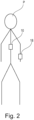
- Fig. 2 shows an example of a patient equipped with the system 10 shown in Fig. 1 .
- the patient P is equipped with the system 10 as disclosed in Fig. 1 .
- the real-time monitoring unit 18 comprises a sensor unit 18a.
- the sensor unit 18a comprises a sensor.
- the sensor monitors blood pressure of the patient P.
- the senor monitors systolic diastolic blood pressure of the patient P.
- the senor is a non-invasive sensor.
- the sensor is wrist blood pressure monitor system.
- the senor is a digital blood pressure monitor system.
- the senor could be an analog blood pressure monitor system.
- the sensor monitors blood pressure continuously in real-time and provides blood pressure data in real-time to the signal processing unit 16.
- the senor measures blood pressure in predefined time-intervals.
- the senor may be or may comprise other embodiments of blood pressure monitor systems, including but not limited to a cuff, an arterial pressure sensor, an optical biometric sensor, an upper arm blood pressure monitor system, a finger blood pressure monitor system or any other type of non-implanted blood pressure monitor system and any type of implantable and/or implanted blood pressure monitor system.
- the senor could measure and/or monitor additionally and/or alternatively other parameters indicating perfusion pressure and/or blood pressure, including but not limited to arterial blood pressure.
- the senor could measure and/or monitor additionally the pulse rate of the patient P.
- the senor could be or could comprise an arterial line.
- the senor could be or could comprise an arterial line in the hospital.
- the sensor unit 18a could comprise more than one sensor and/or at least one sensor base station.
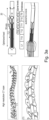
- Fig. 3a shows an example of a lead 20 of the system 10 shown in Fig. 1 , and an embodiment for the implantation side of said lead 20 according to the present invention.
- the dimensions of the lead 20 are designed to perfectly target the posterior roots of the T9-L1 spinal segments.
- a functional mapping procedure could be performed, e.g. in an animal model, e.g. in an animal model of SCI.
- a functional mapping procedure could be performed, e.g. in an animal model, e.g. in an animal model of SCI.
- a functional mapping procedure could be performed, e.g. in an animal model, e.g. in an animal model of SCI.
- the implantation site is a so-called hotspot and preserved across species, as can be further derived from Fig. 3b, Fig. 3c and Fig. 3d :
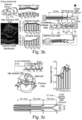
- a functional mapping procedure was performed in a rat model of SCI as described here: In principle, each segment of the spinal cord from T5 to L2 in a rat model of SCI was stimulated and blood pressure responses to monopolar, 50Hz stimulation were recorded.
- T11-T13 are the optimal segments to stimulate in rodents, with the peak response occurring during stimulation of T12, cf. Fig. 4a .
- systolic blood pressure SBP, diastolic blood pressure DBP or mean arterial blood pressure MAB has been measured.
- simulation parameters could vary in a similar approach performed in a human.
- Fig. 4b shows bar diagrams showing quantification of responses at the intermediate stage shown in Fig. 4A , showing preference for T11- T13 across all measures.
- Fig. c shows bar diagrams showing quantification of the responses at T12 over time post injury, including 1 hour (acute), 5 days (subacute), 2 weeks (intermediate), and 1 month (chronic), showing an increase with time post-injury.
- the spinal cord was stimulated at T12 for 30 minutes and classic immunohistochemistry was used to identify active neurons (using the immediate early gene Fos, Fos Proto-Oncogene, AP-1 Transcription Factor Subunit) within the splanchnic ganglia.
- T11-T13 segments preferentially activate sympathetic structures and stimulation of these segments can modulate blood pressure
- high resolution CT and MRI scans were performed to accurately identify the relationship between spinal segments and vertebral levels.
- biocompatible electronic lead 20 spinal implants were designed with the exact dimensions required to stimulate T11-T13, with the lead 20 placed immediately under the T9-T12 vertebra, cf. Fig. 3 .
- This design of a lead 20 could thus be easily scaled to any animal or human model using MRI technology and computational modelling.
- the design of the lead 20 is based off key anatomical features (using a rat model as an animal model)
- the lead 20 dimensions (c.f. Fig. 3 ) are designed to perfectly target the posterior roots of the T11-T13 spinal segments of rats, which have determined are critical for the maintenance of blood pressure using epidural electrical stimulation.
- Fig. 4d shows the functional mapping in a non-human primate and demonstrates the conservation of the hotspot (please cf. also Fig. 3a-3d ).
- Fig. 5 shows activation of natural frequency aspects within the systolic blood pressure signal during an orthostatic stimulus in uninjured and SCI rats.
- Heat represents the frequency power at a given wavelet band.
- the dotted line represents the onset of the orthostatic stimulus.
- a stimulation paradigm could be designed that mimics the natural state of the intact sympathetic nervous system.
- frequency oscillation overlays could be optimized, which in an intact system originate in supraspinal/spinal structures responsible for blood pressure control (i.e., the rostral ventrolateral medulla/spinal cord), and elicit a 0.1 Hz low frequency oscillation sympathetic pre-ganglionic neurons.
- a biomimetic stimulation paradigm is described that reproduces the natural supraspinal sympathetic drive and when coupled with a range of standard parameters (frequency of 10Hz-10kHz, amplitude of 0-1A or 0-15V, pulse width of 1-500 ⁇ s), achieves biologically relevant BIO control over blood pressure after spinal cord injury.
- BIO paradigm recapitulates natural dynamics of the autonomic nervous system using wavelet decomposition, where an increase in the frequency power within the systolic blood pressure signal upon activation of the stimulation is observed.
- Fig. 6 shows activation of natural frequency aspects within the systolic blood pressure signal using biologically relevant BIO stimulation.
- Heat represents the frequency power at a given wavelet band.
- the dotted line represents the onset of the stimulation. 30s of data are shown.
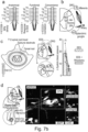
- Fig. 7a shows a schematical overview of the activation of sympathetic neurons according to the present invention.
- Stimulation enters through the posterior roots of the dorsal root ganglion DRG and activates sympathetic pre-ganglionic neurons SPN, which then activate splanchic ganglia SG responsible for blood pressure.
- Fig. 7b shows a schematical overview of mechanisms, by which EES stabilizes hemodynamics.
- Part a shows the intraspinal density of neurons retrogradely traced from the splanchnic ganglia, amplitude of pressor responses to TESS applied to each segment, and concordance between anatomical and functional datasets.
- Part b shows hypothetical circuits activated by TESS to elicit blood vessel constriction.
- Part c shows color-coded electrical potentials following TESS applied to the spinal cord suggesting the exclusive activation of afferent fibres.
- Part d shows trans-synaptic retrograde tracing revealing interneurons connected to splanchnic ganglia.
- Part e shows interneurons. These interneurons express the excitatory marker Slc17a6, and receive vGlut1 synapses from large-diameter proprioceptive afferents.
Claims (9)
- Système (10) de neuromodulation et/ou de neurostimulation, pour le traitement d'un mammifère, comprenant au moins :au moins une unité de commande (12) configurée et agencée pour fournir des données de stimulation ;au moins une unité de stimulation (14) configurée et agencée pour fournir une impulsion de stimulation ;au moins une unité de surveillance en temps réel (18) ;au moins une unité de traitement du signal (16) ;dans lequel le système (10) est configuré et agencé pour commander la pression sanguine, dans lequel l'unité de stimulation (14) est construite pour comprendre un plomb (20) et dans lequel le plomb (20) est capable de fournir une stimulation à la moëlle épinière au niveau T9-L1 et est configuré à cette fin ;caractérisé en ce que :
l'unité de commande (12) comprend un module de commande d'oscillation, dans lequel le module de commande d'oscillation est configuré et agencé pour fournir un courant entrant à oscillation à faible fréquence de 0,01 Hz à 0,2 Hz à une amplitude et/ou une fréquence des données de stimulation. - Système (10) selon la revendication 1, caractérisé en ce que le plomb (20) est capable de fournir une stimulation à la moëlle épinière au niveau T9-T12 et est configuré à cette fin.
- Système (10) selon la revendication 1 ou 2, caractérisé en ce que le plomb (20) peut être positionné de façon subdurale et/ou épidurale au moins en partie au niveau et/ou entre le niveau des vertèbres T9-L1, notamment au moins en partie sous les vertèbres T9-L1 et est configuré à cette fin.
- Système (10) selon la revendication 1, la revendication 2 ou la revendication 3, caractérisé en ce que les données de stimulation comprennent au moins la fréquence, l'amplitude et la largeur d'impulsion, dans lequel la fréquence est de 10Hz-10 kHz, l'amplitude est de 0-1 A ou 0-15 V et la largeur d'impulsion est de 1-500 ps.
- Système (10) selon l'une quelconque des revendications précédentes, caractérisé en ce que l'unité de stimulation (14) est configurée et agencée pour fournir au moins une impulsion de stimulation à train de rafales.
- Système (10) selon la revendication 5, caractérisé en ce que l'unité de stimulation (14) est configurée et agencée pour fournir au moins une rafale de plusieurs impulsions, de préférence de 2 à 5 impulsions.
- Système (10) selon l'une quelconque des revendications précédentes, caractérisé en ce que le module de commande d'oscillation est configuré et agencé pour fournir une entrée d'oscillation à faible fréquence 0,1 Hz en amplitude et/ou en fréquence.
- Système (10) selon l'une quelconque des revendications précédentes, caractérisé en ce que l'unité de commande (12) comprend un module de commande du temps, dans lequel le module de commande du temps est configuré et agencé pour fournir un temps de décalage.
- Système (10) selon la revendication 8, caractérisé en ce que le décalage de temps prévu par le module de commande du temps est un décalage de temps de 1-50 ms.
Priority Applications (1)
| Application Number | Priority Date | Filing Date | Title |
|---|---|---|---|
| EP23183326.0A EP4245358A3 (fr) | 2019-05-15 | 2020-05-14 | Système et procédé de commande de fonction autonome |
Applications Claiming Priority (2)
| Application Number | Priority Date | Filing Date | Title |
|---|---|---|---|
| EP19174556 | 2019-05-15 | ||
| PCT/EP2020/063564 WO2020229646A1 (fr) | 2019-05-15 | 2020-05-14 | Système et procédé de contrôle de fonction autonome |
Related Child Applications (1)
| Application Number | Title | Priority Date | Filing Date |
|---|---|---|---|
| EP23183326.0A Division EP4245358A3 (fr) | 2019-05-15 | 2020-05-14 | Système et procédé de commande de fonction autonome |
Publications (2)
| Publication Number | Publication Date |
|---|---|
| EP3969100A1 EP3969100A1 (fr) | 2022-03-23 |
| EP3969100B1 true EP3969100B1 (fr) | 2023-07-12 |
Family
ID=66554218
Family Applications (2)
| Application Number | Title | Priority Date | Filing Date |
|---|---|---|---|
| EP23183326.0A Pending EP4245358A3 (fr) | 2019-05-15 | 2020-05-14 | Système et procédé de commande de fonction autonome |
| EP20726109.0A Active EP3969100B1 (fr) | 2019-05-15 | 2020-05-14 | Système de contrôle de fonction autonome |
Family Applications Before (1)
| Application Number | Title | Priority Date | Filing Date |
|---|---|---|---|
| EP23183326.0A Pending EP4245358A3 (fr) | 2019-05-15 | 2020-05-14 | Système et procédé de commande de fonction autonome |
Country Status (6)
| Country | Link |
|---|---|
| US (1) | US20220184386A1 (fr) |
| EP (2) | EP4245358A3 (fr) |
| JP (1) | JP2022533945A (fr) |
| CN (1) | CN114450060A (fr) |
| DE (1) | DE23183326T1 (fr) |
| WO (1) | WO2020229646A1 (fr) |
Family Cites Families (13)
| Publication number | Priority date | Publication date | Assignee | Title |
|---|---|---|---|---|
| SE346468B (fr) | 1969-02-24 | 1972-07-10 | Lkb Medical Ab | |
| US6058331A (en) | 1998-04-27 | 2000-05-02 | Medtronic, Inc. | Apparatus and method for treating peripheral vascular disease and organ ischemia by electrical stimulation with closed loop feedback control |
| US7603174B2 (en) * | 2004-10-21 | 2009-10-13 | Advanced Neuromodulation Systems, Inc. | Stimulation of the amygdalohippocampal complex to treat neurological conditions |
| US20070027495A1 (en) | 2005-07-29 | 2007-02-01 | Medtronic, Inc. | External bladder sensor for sensing bladder condition |
| US20070156200A1 (en) | 2005-12-29 | 2007-07-05 | Lilian Kornet | System and method for regulating blood pressure and electrolyte balance |
| US7797041B2 (en) | 2006-10-11 | 2010-09-14 | Cardiac Pacemakers, Inc. | Transcutaneous neurostimulator for modulating cardiovascular function |
| JP5366146B2 (ja) | 2007-10-15 | 2013-12-11 | 国立大学法人九州大学 | 経皮刺激による血圧安定化装置 |
| WO2010104700A1 (fr) * | 2009-03-09 | 2010-09-16 | Cardiac Pacemakers, Inc. | Systèmes de modulation nerveuse autonome comprenant des électrodes implantables dans un vaisseau lymphatique |
| US20130289650A1 (en) | 2012-04-25 | 2013-10-31 | Pacesetter, Inc. | Neuromodulation for Hypertension Control |
| US8868188B2 (en) * | 2012-09-20 | 2014-10-21 | Boston Scientific Neuromodulation Corporation | Method for treating hypertension via electrical stimulation of neural structures |
| WO2018089981A1 (fr) * | 2016-11-14 | 2018-05-17 | Boston Scientific Neuromodulation Corporation | Système de commande de stimulation de moelle épinière pour traiter l'hypertension |
| WO2018148844A1 (fr) | 2017-02-17 | 2018-08-23 | The University Of British Columbia | Appareil et procédés de maintien des fonctions physiologiques |
| CA3091769A1 (fr) * | 2018-02-20 | 2019-08-29 | Presidio Medical, Inc. | Procedes et systemes pour bloc de conduction nerveuse |
-
2020
- 2020-05-14 US US17/595,382 patent/US20220184386A1/en active Pending
- 2020-05-14 CN CN202080036233.0A patent/CN114450060A/zh active Pending
- 2020-05-14 EP EP23183326.0A patent/EP4245358A3/fr active Pending
- 2020-05-14 EP EP20726109.0A patent/EP3969100B1/fr active Active
- 2020-05-14 WO PCT/EP2020/063564 patent/WO2020229646A1/fr unknown
- 2020-05-14 JP JP2021567923A patent/JP2022533945A/ja active Pending
- 2020-05-14 DE DE23183326.0T patent/DE23183326T1/de active Pending
Also Published As
| Publication number | Publication date |
|---|---|
| US20220184386A1 (en) | 2022-06-16 |
| EP3969100A1 (fr) | 2022-03-23 |
| JP2022533945A (ja) | 2022-07-27 |
| CN114450060A (zh) | 2022-05-06 |
| EP4245358A3 (fr) | 2023-11-22 |
| WO2020229646A1 (fr) | 2020-11-19 |
| EP4245358A2 (fr) | 2023-09-20 |
| DE23183326T1 (de) | 2023-12-28 |
Similar Documents
| Publication | Publication Date | Title |
|---|---|---|
| US11883664B2 (en) | Systems and methods for closed-loop pain management | |
| US8560072B2 (en) | System for neural control of respiration | |
| US9707396B2 (en) | Cortical potential monitoring | |
| AU2009308143B2 (en) | Dynamic cranial nerve stimulation based on brain state determination from cardiac data | |
| KR100990414B1 (ko) | 췌장 장애를 치료하기 위한 자율 신경의 자극 방법 | |
| US20030149450A1 (en) | Brainstem and cerebellar modulation of cardiovascular response and disease | |
| US11235154B2 (en) | Apparatus and methods for maintaining physiological functions | |
| EP3969100B1 (fr) | Système de contrôle de fonction autonome | |
| US20210370066A1 (en) | Neuromodulation and/or neurostimulation system | |
| US20160045739A1 (en) | Systems for treating anxiety and anxiety-associated disorders | |
| CN115551587A (zh) | 患者专用优化算法 | |
| US20220125374A1 (en) | System and method for closed loop control of autonomic function | |
| US20220126099A1 (en) | Physiologic signal transmitter and receiver device | |
| WO2010022071A2 (fr) | Procédés améliorés de contrôle de la santé cardiovasculaire | |
| WO2024100020A1 (fr) | Système de contrôle mictionnel chez un mammifère souffrant d'un disfonctionnement de la vessie |
Legal Events
| Date | Code | Title | Description |
|---|---|---|---|
| STAA | Information on the status of an ep patent application or granted ep patent |
Free format text: STATUS: UNKNOWN |
|
| STAA | Information on the status of an ep patent application or granted ep patent |
Free format text: STATUS: THE INTERNATIONAL PUBLICATION HAS BEEN MADE |
|
| PUAI | Public reference made under article 153(3) epc to a published international application that has entered the european phase |
Free format text: ORIGINAL CODE: 0009012 |
|
| STAA | Information on the status of an ep patent application or granted ep patent |
Free format text: STATUS: REQUEST FOR EXAMINATION WAS MADE |
|
| 17P | Request for examination filed |
Effective date: 20211215 |
|
| AK | Designated contracting states |
Kind code of ref document: A1 Designated state(s): AL AT BE BG CH CY CZ DE DK EE ES FI FR GB GR HR HU IE IS IT LI LT LU LV MC MK MT NL NO PL PT RO RS SE SI SK SM TR |
|
| DAV | Request for validation of the european patent (deleted) | ||
| DAX | Request for extension of the european patent (deleted) | ||
| GRAP | Despatch of communication of intention to grant a patent |
Free format text: ORIGINAL CODE: EPIDOSNIGR1 |
|
| STAA | Information on the status of an ep patent application or granted ep patent |
Free format text: STATUS: GRANT OF PATENT IS INTENDED |
|
| INTG | Intention to grant announced |
Effective date: 20230208 |
|
| GRAS | Grant fee paid |
Free format text: ORIGINAL CODE: EPIDOSNIGR3 |
|
| GRAA | (expected) grant |
Free format text: ORIGINAL CODE: 0009210 |
|
| STAA | Information on the status of an ep patent application or granted ep patent |
Free format text: STATUS: THE PATENT HAS BEEN GRANTED |
|
| P01 | Opt-out of the competence of the unified patent court (upc) registered |
Effective date: 20230517 |
|
| AK | Designated contracting states |
Kind code of ref document: B1 Designated state(s): AL AT BE BG CH CY CZ DE DK EE ES FI FR GB GR HR HU IE IS IT LI LT LU LV MC MK MT NL NO PL PT RO RS SE SI SK SM TR |
|
| REG | Reference to a national code |
Ref country code: CH Ref legal event code: EP |
|
| REG | Reference to a national code |
Ref country code: IE Ref legal event code: FG4D |
|
| REG | Reference to a national code |
Ref country code: DE Ref legal event code: R096 Ref document number: 602020013703 Country of ref document: DE |
|
| REG | Reference to a national code |
Ref country code: NL Ref legal event code: FP |
|
| REG | Reference to a national code |
Ref country code: LT Ref legal event code: MG9D |
|
| REG | Reference to a national code |
Ref country code: AT Ref legal event code: MK05 Ref document number: 1586449 Country of ref document: AT Kind code of ref document: T Effective date: 20230712 |
|
| PG25 | Lapsed in a contracting state [announced via postgrant information from national office to epo] |
Ref country code: GR Free format text: LAPSE BECAUSE OF FAILURE TO SUBMIT A TRANSLATION OF THE DESCRIPTION OR TO PAY THE FEE WITHIN THE PRESCRIBED TIME-LIMIT Effective date: 20231013 |
|
| PG25 | Lapsed in a contracting state [announced via postgrant information from national office to epo] |
Ref country code: ES Free format text: LAPSE BECAUSE OF FAILURE TO SUBMIT A TRANSLATION OF THE DESCRIPTION OR TO PAY THE FEE WITHIN THE PRESCRIBED TIME-LIMIT Effective date: 20230712 |
|
| PG25 | Lapsed in a contracting state [announced via postgrant information from national office to epo] |
Ref country code: IS Free format text: LAPSE BECAUSE OF FAILURE TO SUBMIT A TRANSLATION OF THE DESCRIPTION OR TO PAY THE FEE WITHIN THE PRESCRIBED TIME-LIMIT Effective date: 20231112 |
|
| PG25 | Lapsed in a contracting state [announced via postgrant information from national office to epo] |
Ref country code: SE Free format text: LAPSE BECAUSE OF FAILURE TO SUBMIT A TRANSLATION OF THE DESCRIPTION OR TO PAY THE FEE WITHIN THE PRESCRIBED TIME-LIMIT Effective date: 20230712 Ref country code: RS Free format text: LAPSE BECAUSE OF FAILURE TO SUBMIT A TRANSLATION OF THE DESCRIPTION OR TO PAY THE FEE WITHIN THE PRESCRIBED TIME-LIMIT Effective date: 20230712 Ref country code: PT Free format text: LAPSE BECAUSE OF FAILURE TO SUBMIT A TRANSLATION OF THE DESCRIPTION OR TO PAY THE FEE WITHIN THE PRESCRIBED TIME-LIMIT Effective date: 20231113 Ref country code: NO Free format text: LAPSE BECAUSE OF FAILURE TO SUBMIT A TRANSLATION OF THE DESCRIPTION OR TO PAY THE FEE WITHIN THE PRESCRIBED TIME-LIMIT Effective date: 20231012 Ref country code: LV Free format text: LAPSE BECAUSE OF FAILURE TO SUBMIT A TRANSLATION OF THE DESCRIPTION OR TO PAY THE FEE WITHIN THE PRESCRIBED TIME-LIMIT Effective date: 20230712 Ref country code: LT Free format text: LAPSE BECAUSE OF FAILURE TO SUBMIT A TRANSLATION OF THE DESCRIPTION OR TO PAY THE FEE WITHIN THE PRESCRIBED TIME-LIMIT Effective date: 20230712 Ref country code: IS Free format text: LAPSE BECAUSE OF FAILURE TO SUBMIT A TRANSLATION OF THE DESCRIPTION OR TO PAY THE FEE WITHIN THE PRESCRIBED TIME-LIMIT Effective date: 20231112 Ref country code: HR Free format text: LAPSE BECAUSE OF FAILURE TO SUBMIT A TRANSLATION OF THE DESCRIPTION OR TO PAY THE FEE WITHIN THE PRESCRIBED TIME-LIMIT Effective date: 20230712 Ref country code: GR Free format text: LAPSE BECAUSE OF FAILURE TO SUBMIT A TRANSLATION OF THE DESCRIPTION OR TO PAY THE FEE WITHIN THE PRESCRIBED TIME-LIMIT Effective date: 20231013 Ref country code: FI Free format text: LAPSE BECAUSE OF FAILURE TO SUBMIT A TRANSLATION OF THE DESCRIPTION OR TO PAY THE FEE WITHIN THE PRESCRIBED TIME-LIMIT Effective date: 20230712 Ref country code: ES Free format text: LAPSE BECAUSE OF FAILURE TO SUBMIT A TRANSLATION OF THE DESCRIPTION OR TO PAY THE FEE WITHIN THE PRESCRIBED TIME-LIMIT Effective date: 20230712 Ref country code: AT Free format text: LAPSE BECAUSE OF FAILURE TO SUBMIT A TRANSLATION OF THE DESCRIPTION OR TO PAY THE FEE WITHIN THE PRESCRIBED TIME-LIMIT Effective date: 20230712 |
|
| PG25 | Lapsed in a contracting state [announced via postgrant information from national office to epo] |
Ref country code: PL Free format text: LAPSE BECAUSE OF FAILURE TO SUBMIT A TRANSLATION OF THE DESCRIPTION OR TO PAY THE FEE WITHIN THE PRESCRIBED TIME-LIMIT Effective date: 20230712 |
|
| PG25 | Lapsed in a contracting state [announced via postgrant information from national office to epo] |
Ref country code: SM Free format text: LAPSE BECAUSE OF FAILURE TO SUBMIT A TRANSLATION OF THE DESCRIPTION OR TO PAY THE FEE WITHIN THE PRESCRIBED TIME-LIMIT Effective date: 20230712 Ref country code: RO Free format text: LAPSE BECAUSE OF FAILURE TO SUBMIT A TRANSLATION OF THE DESCRIPTION OR TO PAY THE FEE WITHIN THE PRESCRIBED TIME-LIMIT Effective date: 20230712 Ref country code: EE Free format text: LAPSE BECAUSE OF FAILURE TO SUBMIT A TRANSLATION OF THE DESCRIPTION OR TO PAY THE FEE WITHIN THE PRESCRIBED TIME-LIMIT Effective date: 20230712 Ref country code: DK Free format text: LAPSE BECAUSE OF FAILURE TO SUBMIT A TRANSLATION OF THE DESCRIPTION OR TO PAY THE FEE WITHIN THE PRESCRIBED TIME-LIMIT Effective date: 20230712 Ref country code: CZ Free format text: LAPSE BECAUSE OF FAILURE TO SUBMIT A TRANSLATION OF THE DESCRIPTION OR TO PAY THE FEE WITHIN THE PRESCRIBED TIME-LIMIT Effective date: 20230712 Ref country code: SK Free format text: LAPSE BECAUSE OF FAILURE TO SUBMIT A TRANSLATION OF THE DESCRIPTION OR TO PAY THE FEE WITHIN THE PRESCRIBED TIME-LIMIT Effective date: 20230712 |