EP3968302A1 - Signal measurement unit - Google Patents
Signal measurement unit Download PDFInfo
- Publication number
- EP3968302A1 EP3968302A1 EP20806545.8A EP20806545A EP3968302A1 EP 3968302 A1 EP3968302 A1 EP 3968302A1 EP 20806545 A EP20806545 A EP 20806545A EP 3968302 A1 EP3968302 A1 EP 3968302A1
- Authority
- EP
- European Patent Office
- Prior art keywords
- input
- measurement unit
- value
- analogue
- unit
- Prior art date
- Legal status (The legal status is an assumption and is not a legal conclusion. Google has not performed a legal analysis and makes no representation as to the accuracy of the status listed.)
- Granted
Links
Images





Classifications
-
- H—ELECTRICITY
- H04—ELECTRIC COMMUNICATION TECHNIQUE
- H04Q—SELECTING
- H04Q9/00—Arrangements in telecontrol or telemetry systems for selectively calling a substation from a main station, in which substation desired apparatus is selected for applying a control signal thereto or for obtaining measured values therefrom
-
- G—PHYSICS
- G01—MEASURING; TESTING
- G01D—MEASURING NOT SPECIALLY ADAPTED FOR A SPECIFIC VARIABLE; ARRANGEMENTS FOR MEASURING TWO OR MORE VARIABLES NOT COVERED IN A SINGLE OTHER SUBCLASS; TARIFF METERING APPARATUS; MEASURING OR TESTING NOT OTHERWISE PROVIDED FOR
- G01D5/00—Mechanical means for transferring the output of a sensing member; Means for converting the output of a sensing member to another variable where the form or nature of the sensing member does not constrain the means for converting; Transducers not specially adapted for a specific variable
- G01D5/12—Mechanical means for transferring the output of a sensing member; Means for converting the output of a sensing member to another variable where the form or nature of the sensing member does not constrain the means for converting; Transducers not specially adapted for a specific variable using electric or magnetic means
- G01D5/244—Mechanical means for transferring the output of a sensing member; Means for converting the output of a sensing member to another variable where the form or nature of the sensing member does not constrain the means for converting; Transducers not specially adapted for a specific variable using electric or magnetic means influencing characteristics of pulses or pulse trains; generating pulses or pulse trains
Definitions
- the present invention relates to a signal measurement unit that processes analogue signals and pulse signals.
- Patent literature 1 discloses a technique for detecting the maximum and minimum of an input analogue signal and counting the number of times thereof.
- One aspect of the present invention is to save on costs and space when processing analogue signals and pulse signals.
- a signal measurement unit includes: an input unit that inputs an electric signal output from an external signal output equipment; an analogue measurement unit that measures a voltage value of the electric signal input in the input unit as an analogue value; and a counting measurement unit that counts at least one of the number of times that the voltage value of the electric signal input in the input unit has equalled or exceeded a predetermined first threshold value and the number of times that the voltage value has equalled or fallen below a predetermined second threshold value.
- the input unit selects whether to transmit the electric signal that is input to the analogue measurement unit or to the counting measurement unit.
- FIGS. 1 to 8 an embodiment according to one aspect of the present invention (hereinafter, also referred to as “the present embodiment”) is described with reference to FIGS. 1 to 8 .
- the same or corresponding parts in the drawings are designated by the same reference numerals, and the description thereof will not be repeated.
- a signal measurement unit 2 is described as a typical example of a counter unit.
- FIG. 1 an overview of a measurement system 1 including the signal measurement unit 2 is described with reference to FIG. 1 .
- FIG. 1 is a block diagram showing a configuration of the measurement system 1 according to the present embodiment. As shown in FIG. 1 , the measurement system 1 includes the signal measurement unit 2 and a PLC 3.
- the signal measurement unit 2 has a function of transmitting an analogue input value from a sensor 4 to the PLC 3 and a function of counting the number of times that the analogue input value from an encoder 5 crosses a specific threshold value and transmitting the count measurement value to the PLC 3, and switches between the analogue output signal and the count measurement value as a transmission target.
- the PLC 3 is an industrial controller and controls a device to be controlled.
- a control unit of the PLC 3 may be bus-connected to the signal measurement unit 2, or may be connected to the signal measurement unit 2 by EtherCAT (registered trademark), EtherNet/IP (registered trademark), DeviceNet (registered trademark), CompoNet (registered trademark), or the like via a communication coupler.
- EtherCAT registered trademark
- EtherNet/IP registered trademark
- DeviceNet registered trademark
- CompoNet registered trademark
- the PLC 3 acquires the analogue output signal and the count measurement value from the signal measurement unit 2 and performs predetermined processing (for example, an inspection of the shape of a workpiece or the like), for example.
- the sensor 4 measures various data (for example, a vertical position of a workpiece moved by a conveyor or other data) and transmits the data to the signal measurement unit 2.
- the encoder 5 detects various data (for example, a lateral position of the workpiece moved by the conveyor or other data) and transmits a pulse signal corresponding to the detection result to the signal measurement unit 2.
- another signal output equipment for example, a flow meter or the like may also be used.
- the signal measurement unit 2 includes an input unit 21, an analogue measurement unit 22, a counting measurement unit 23, an input setting unit 24, a threshold value setting unit 25, a comparison portion 26, and an output control unit 27.
- the input unit 21 inputs an electric signal output from the sensor 4 and the encoder 5 (the external signal output equipment).
- the analogue measurement unit 22 measures the voltage value of the electric signal input in the input unit 21 as an analogue value.
- the counting measurement unit 23 counts at least one of the number of times that the voltage value of the electric signal input in the input unit 21 has equalled or exceeded a High level (a predetermined first threshold value) and the number of times that the voltage value of the electric signal input in the input unit 21 has equalled or fallen below a Low level (a predetermined second threshold value). Then, the input unit 21 selects whether to transmit the input electric signal to the analogue measurement unit 22 or to the counting measurement unit 23.
- the counting measurement unit 23 can count the pulse having a speed up to about 1/4 of an A/D conversion speed (a sampling frequency) of an analogue unit.
- the input unit 21 may include input terminals Ch1 and Ch2 (a plurality of input terminals). In this case, the input unit 21 selects whether to transmit the input electric signal to the analogue measurement unit 22 or to the counting measurement unit 23 for each of the input terminals Ch1 and Ch2.
- the input setting unit 24 receives a setting instruction of whether to transmit the electric signal input in the input unit 21 to the analogue measurement unit 22 or to the counting measurement unit 23 via a communication line.
- the threshold value setting unit 25 receives a setting instruction of at least one of the High level and the Low level via a communication line.
- the comparison portion 26 determines matching between the count measurement value and a target value.
- the count measurement value is obtained by measuring the electric signal input at the input terminal Ch1 (a first input terminal) by the counting measurement unit 23. If the comparison portion 26 determines that the count measurement value matches the target value, the output control unit 27 may output the analogue measurement value obtained by measuring the electric signal input at the input terminal Ch2 (a second input terminal) by the analogue measurement unit 22 at that time.
- the output control unit 27 may store the analogue measurement value obtained by measuring the electric signal input at the input terminal Ch2 by the analogue measurement unit 22 in a buffer at that time, and output a plurality of analogue measurement values stored in the buffer to a PLC (an external device) 4 in a predetermined communication cycle for communication.
- the signal measurement unit 2 may be configured to receive the setting instruction of whether to transmit the input electric signal to the analogue measurement unit 22 or to the counting measurement unit 23 and the setting instruction of a threshold value such as the High level, the Low level, or the like from a setting value input device such as a notebook PC or the like via a universal serial bus (USB), for example, or may be configured to receive the setting instructions from the PLC 3 to which the setting value input device is connected via a communication network (Ethernet (registered trademark) or the like).
- a communication network Ethernet (registered trademark) or the like.
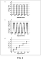
- FIG. 2 is a diagram showing an example of input/output data of the signal measurement unit 2 according to the present embodiment.
- (a) of FIG. 2 shows an example of input data of the signal measurement unit 2, and particularly shows a waveform of the pulse signal output from a rotary encoder, a flow meter, or the like.
- FIG. 2 shows an example of output data of the signal measurement unit 2, and particularly shows an example of the output data when the signal measurement unit 2 is in an analogue mode (a normal mode).
- the signal measurement unit 2 outputs the pulse signal in (a) of FIG. 2 as an analogue signal to the PLC 3 as shown in (b) of FIG. 2 .
- FIG. 2 shows an example of output data of the signal measurement unit 2, and particularly shows an example of the output data when the signal measurement unit 2 is in a counter mode (a simple counter mode).
- the signal measurement unit 2 outputs the count value for the pulse signal in (a) of FIG. 2 to the PLC 3 as shown in (c) of FIG. 2 . That is, the signal measurement unit 2 can realize the same function as the high-speed counter unit in a state of including a hardware circuit of an analogue input unit.
- the signal measurement unit 2 has a function of acquiring an analogue signal from another input terminal and outputting the analogue signal to the PLC 3 at the timing when the count value of the pulse signal from one input terminal reaches the target value set previously.
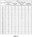
- FIG. 3 is a diagram showing a numerical value example of input/output data of the signal measurement unit 2 according to the present embodiment.
- the signal measurement unit 2 in the case of the analogue mode, the signal measurement unit 2 outputs the analogue input value as an analogue signal.
- the signal measurement unit 2 In the case of the counter mode, the signal measurement unit 2 outputs the count value corresponding to the analogue input value.
- the counter mode can be selected from any of a rising number of times counting mode, a falling number of times counting mode, and a rising/falling number of times counting mode.
- the signal measurement unit 2 adds 1 to the count value when the analogue input value changes from 2.5 [V] to 5 [V] (when the elapsed time is 60 and 160). In the case of the falling number of times counting mode, the signal measurement unit 2 adds 1 to the count value when the analogue input value changes from 2.5 [V] to 0 [V] (when the elapsed time is 110 and 210).
- the signal measurement unit 2 adds 1 to the count value when the analogue input value changes from 2.5 [V] to 5 [V] and when the analogue input value changes from 2.5 [V] to 0 [V].
- FIG. 4 is a diagram showing an example in which the signal measurement unit 2 according to the present embodiment counts using pulse signals in two channels.
- (a) of FIG. 4 shows an example of phase difference input pulses.
- (b) of FIG. 4 shows an example of the count value for the phase difference input pulses.
- the signal measurement unit 2 inputs two-phase signals (an A phase and a B phase) and adds or subtracts the count value according to the phase difference between the signals (quadruple).
- FIG. 4 shows an example of addition/subtraction pulses.
- (d) of FIG. 4 shows an example of the count value for the addition/subtraction pulses.
- the signal measurement unit 2 inputs the addition pulse signal and the subtraction pulse signal, and adds or subtracts the count value according to a change in the signal.
- the signal measurement unit 2 performs counting processing corresponding to the phase difference input pulse or the addition/subtraction pulse according to the set modes (phase difference input pulse processing mode and addition/subtraction pulse processing mode).
- the mode setting is performed according to the setting instruction of a user.
- FIG. 5 is a diagram showing an example of a method of switching between the analogue mode and the counter mode in the signal measurement unit 2 according to the present embodiment.
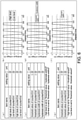
- FIG. 6 is a diagram showing an example of a method of setting a threshold value in the signal measurement unit 2 according to the present embodiment.
- (a), (c), and (e) of FIG. 6 respectively show an example of the setting screen displayed by the tool used in the setting value input device such as a PC or the like.
- the count value-matching analogue sampling function indicates whether to enable or disable the function of sampling the analogue values with matching count values (hereinafter referred to as "sampling function"), and specifies the input terminal to acquire the pulse signal to be counted when the sampling function is enabled.
- the count value-matching analogue sampling target (Ch1) specifies whether to enable or disable the input of the analogue value being a target of the sampling function for the input terminal Ch1.
- the count value-matching analogue sampling target (Ch2) specifies whether to enable or disable the input of the analogue value being a target of the sampling function for the input terminal Ch2.
- the count value-matching analogue sampling mode (hereinafter referred to as "sampling mode") specifies a setting method of a count value being a target.
- sampling mode "start count value/end count value/point number specification”, “change amount specification”, or “table specification” can be selected.
- a start count value, an end count value, and a point number that need to be set when the "start count value/end count value/point number specification" is specified in the sampling mode is described below.
- a first count value is set as the start count value.
- a last count value is set as the end count value.
- the number of the count values is set as the point number.
- the count value (Ch1) is a numerical value (10, 20, ..., 90, 100) specified by the start count value, the end count value, and the point number in (a) of FIG. 7 .
- the analogue value (Ch2) is an analogue value at the input terminal Ch2 at the timing when the count value is acquired by the pulse signal input to the input terminal Ch1.
- FIG. 8 is a flowchart showing processing of outputting the analogue value and the count value according to the present embodiment in association with each other.
- the comparison portion 26 reads out the count value from the counting measurement unit 23 and acquires the target value according to the pointer to the target value. Moreover, the counting measurement unit 23 counts the number of times that the pulse signal input at the input terminal Ch1 has equalled or exceeded the High level of the counter at any time. In addition, a plurality of target values are stored in a predetermined memory.
- the comparison portion 26 determines whether or not the count value is equal to or greater than the target value. When the count value is equal to or greater than the target value (YES in Step S802), the signal measurement unit 2 executes processing of Step S803. When the count value is not equal to or greater than the target value (less than the target value) (YES in Step S802), the signal measurement unit 2 executes the processing of Step S801 again.
- the output control unit 27 stores, in the buffer, the analogue measurement value obtained by measuring the electric signal input at the input terminal Ch2 by the analogue measurement unit 22.
- the signal measurement unit 2 updates the pointer to the target value.
- the signal measurement unit 2 determines whether or not the count value has reached the end count value. When the count value has reached the end count value (YES in Step S805), the signal measurement unit 2 executes processing of Step 806. When the count value has not reached the end count value (NO in Step S805), the signal measurement unit 2 executes the processing of Step 801 again.
- the output control unit 27 outputs the plurality of analogue measurement values stored in the buffer to the PLC 3 in a predetermined communication cycle for communication.
- the signal measurement unit 2 stores, in the buffer, analogue input values of other channels at the timing when the count value reaches the value specified by the user, and later collectively transfers the analogue input values to the PLC 3.
- the method of specifying the count value has following variations.
- the control blocks of the signal measurement unit 2 may be implemented by a logic circuit (hardware) formed in an integration circuit (an IC chip) or the like, or may be implemented by software.
- the signal measurement unit 2 includes a computer that executes instructions of a program being software for implementing each function.
- the computer includes, for example, one or more processors and a computer-readable recording medium that stores the program.
- the processor reads the program from the recording medium and executes the program, and thereby the object of the present invention is achieved.
- the processor may be, for example, a central processing unit (CPU).
- the recording medium may be a "non-temporary tangible medium", such as a read only memory (ROM), as well as a tape, a disk, a card, a semiconductor memory, a programmable logic circuit, or the like.
- the recording medium may further include a random access memory (RAM) or the like that deploys the above program.
- the above program may be supplied to the computer via any transmission medium capable of transmitting the program (communication network, broadcast wave, or the like).
- one aspect of the present invention may also be implemented in a form of a data signal embedded in a carrier wave, in which the above program is embodied by electronic transmission.
- the signal measurement unit includes: an input unit that inputs an electric signal output from an external signal output equipment; an analogue measurement unit that measures a voltage value of the electric signal input in the input unit as an analogue value; and a counting measurement unit that counts at least one of the number of times that the voltage value of the electric signal input in the input unit has equalled or exceeded a predetermined first threshold value and the number of times that the voltage value has equalled or fallen below a predetermined second threshold value.
- the input unit selects whether to transmit the electric signal that is input to the analogue measurement unit or to the counting measurement unit.
- the signal measurement unit can be switched between a case of being made to function as an analogue output unit that measures and outputs an analogue value and a case of being made to function as a counter unit that counts and outputs the number of pulses of the pulse signal. Therefore, it is not necessary to prepare both the analogue output unit and the counter unit, and cost saving and space saving can be realized.
- the input unit may include a plurality of input terminals, and may select whether to transmit the electric signal that is input to the analogue measurement unit or to the counting measurement unit for each of the input terminals.
- the counter unit may further include, in the output control unit, an input setting unit that receives a setting instruction of whether to transmit the electric signal input in the input unit to the analogue measurement unit or to the counting measurement unit via a communication line.
- whether to measure and output an analogue value or to count and output the number of pulses of a pulse signal can be set from the outside via a communication line.
- the counter unit may further include a threshold value setting unit that receives a setting instruction of at least one of the first threshold value and the second threshold value via a communication line.
- the value of at least one of the first threshold value and the second threshold value can be changed from the outside via the communication line, and thus a counting operation can be performed according to the characteristic of the signal output equipment that outputs the pulse signal. Therefore, the accuracy of the counting operation can be improved.
- the counter unit may further include: a comparison portion that determines matching between a count measurement value and a target value, the count measurement value being obtained by measuring an electric signal input at the first input terminal of the input terminals by the counting measurement unit; and an output control unit that outputs, if the comparison portion determines that the count measurement value matches the target value, an analogue measurement value obtained by measuring the electric signal input at the second input terminal of the input terminals by the analogue measurement unit at that time.
- the count measurement value is, for example, a value indicating position information of an object to be measured
- the target value that meets the required accuracy is set in advance, and thereby the analogue measurement value of another signal output equipment in the target value can be output. Therefore, the analogue measurement value can be output with sufficient accuracy.
- the communication load and the data processing load on the external device can be suppressed.
- the output control unit may store, in a buffer, an analogue measurement value obtained by measuring the electric signal input at the second input terminal of the input terminals by the analogue measurement unit at that time, and output a plurality of analogue measurement values stored in the buffer to an external device in a predetermined communication cycle for communication.
- the association of the position with the analogue measurement value can be performed with sufficient accuracy without being affected by the communication cycle.
- the signal measurement unit buffers and outputs the analogue measurement value corresponding to the target value, the unevenness of the measurement accuracy due to the unevenness of the moving speed of the measurement target, which occurs when the counter output is performed in a conventional predetermined cycle, can be prevented from occurring.
Landscapes
- Physics & Mathematics (AREA)
- General Physics & Mathematics (AREA)
- Engineering & Computer Science (AREA)
- Computer Networks & Wireless Communication (AREA)
- Arrangements For Transmission Of Measured Signals (AREA)
- Programmable Controllers (AREA)
Abstract
Description
- The present invention relates to a signal measurement unit that processes analogue signals and pulse signals.
- Conventionally, a technique for counting a pulse signal output from a rotary encoder, a flow meter, or the like by a high-speed counter unit is known.
-
- Patent literature 1:
Japanese Patent Laid-Open No. 2005-302006 - Patent literature 2:
Japanese Patent Laid-Open No. 2016-127526 - When a pulse signal is counted, it is necessary to detect a voltage (High or Low) of the pulse by a digital circuit and count the number of times the voltage of the pulse changes, and a high-speed counter unit is indispensable for that purpose.
- Therefore, for example, when an analogue value is sampled and output in synchronization with a position (pulse) of a rotary encoder, it is necessary to separately prepare a high-speed counter unit that counts the pulse signal and a high-speed analogue unit that processes the analogue signal. Regarding this, there is a problem that the cost is increased and a space for installing two devices must be secured.
- Moreover,
Patent literature 1 discloses a technique for detecting the maximum and minimum of an input analogue signal and counting the number of times thereof. In addition, -
Patent literature 2 discloses a technique for binarizing and counting an analogue signal. However, neither of the patent literatures solves the above problem. - One aspect of the present invention is to save on costs and space when processing analogue signals and pulse signals.
- In order to solve the above problems, a signal measurement unit according to one aspect of the present invention includes: an input unit that inputs an electric signal output from an external signal output equipment; an analogue measurement unit that measures a voltage value of the electric signal input in the input unit as an analogue value; and a counting measurement unit that counts at least one of the number of times that the voltage value of the electric signal input in the input unit has equalled or exceeded a predetermined first threshold value and the number of times that the voltage value has equalled or fallen below a predetermined second threshold value. The input unit selects whether to transmit the electric signal that is input to the analogue measurement unit or to the counting measurement unit.
- According to one aspect of the present invention, it is possible to realize cost saving and space saving when processing analogue signals and pulse signals.
-
-
FIG. 1 is a block diagram showing a configuration of a measurement system according toEmbodiment 1 of the present invention. -
FIG. 2 is a diagram showing input/output data of a signal measurement unit according toEmbodiment 1 of the present invention. -
FIG. 3 is a diagram showing a numerical value example of the input/output data of the signal measurement unit according toEmbodiment 1 of the present invention. -
FIG. 4 is a diagram showing an example in which the signal measurement unit according toEmbodiment 1 of the present invention counts using pulse signals in two channels. -
FIG. 5 is a diagram showing an example of a method of switching between an analogue mode and a counter mode in the signal measurement unit according toEmbodiment 1 of the present invention. -
FIG. 6 is a diagram showing an example of a method of setting a threshold value in the signal measurement unit according toEmbodiment 1 of the present invention. -
FIG. 7 is a diagram showing data related to an analogue value and a count value according toEmbodiment 1 of the present invention. -
FIG. 8 is a flowchart showing processing of outputting the analogue value and the count value according toEmbodiment 1 of the present invention in association with each other. - Hereinafter, an embodiment according to one aspect of the present invention (hereinafter, also referred to as "the present embodiment") is described with reference to
FIGS. 1 to 8 . Note that, the same or corresponding parts in the drawings are designated by the same reference numerals, and the description thereof will not be repeated. In the present embodiment, for example, asignal measurement unit 2 is described as a typical example of a counter unit. In order to facilitate understanding of thesignal measurement unit 2 according to one aspect of the present invention, first, an overview of ameasurement system 1 including thesignal measurement unit 2 is described with reference toFIG. 1 . -
FIG. 1 is a block diagram showing a configuration of themeasurement system 1 according to the present embodiment. As shown inFIG. 1 , themeasurement system 1 includes thesignal measurement unit 2 and aPLC 3. - The
signal measurement unit 2 has a function of transmitting an analogue input value from asensor 4 to thePLC 3 and a function of counting the number of times that the analogue input value from anencoder 5 crosses a specific threshold value and transmitting the count measurement value to thePLC 3, and switches between the analogue output signal and the count measurement value as a transmission target. - The
PLC 3 is an industrial controller and controls a device to be controlled. A control unit of thePLC 3 may be bus-connected to thesignal measurement unit 2, or may be connected to thesignal measurement unit 2 by EtherCAT (registered trademark), EtherNet/IP (registered trademark), DeviceNet (registered trademark), CompoNet (registered trademark), or the like via a communication coupler. ThePLC 3 acquires the analogue output signal and the count measurement value from thesignal measurement unit 2 and performs predetermined processing (for example, an inspection of the shape of a workpiece or the like), for example. - The
sensor 4 measures various data (for example, a vertical position of a workpiece moved by a conveyor or other data) and transmits the data to thesignal measurement unit 2. Theencoder 5 detects various data (for example, a lateral position of the workpiece moved by the conveyor or other data) and transmits a pulse signal corresponding to the detection result to thesignal measurement unit 2. Moreover, instead of theencoder 5, another signal output equipment (for example, a flow meter or the like) may also be used. - The
signal measurement unit 2 includes aninput unit 21, ananalogue measurement unit 22, acounting measurement unit 23, aninput setting unit 24, a thresholdvalue setting unit 25, acomparison portion 26, and anoutput control unit 27. - The
input unit 21 inputs an electric signal output from thesensor 4 and the encoder 5 (the external signal output equipment). Theanalogue measurement unit 22 measures the voltage value of the electric signal input in theinput unit 21 as an analogue value. Thecounting measurement unit 23 counts at least one of the number of times that the voltage value of the electric signal input in theinput unit 21 has equalled or exceeded a High level (a predetermined first threshold value) and the number of times that the voltage value of the electric signal input in theinput unit 21 has equalled or fallen below a Low level (a predetermined second threshold value). Then, theinput unit 21 selects whether to transmit the input electric signal to theanalogue measurement unit 22 or to thecounting measurement unit 23. - Moreover, the
counting measurement unit 23 can count the pulse having a speed up to about 1/4 of an A/D conversion speed (a sampling frequency) of an analogue unit. - In addition, the
input unit 21 may include input terminals Ch1 and Ch2 (a plurality of input terminals). In this case, theinput unit 21 selects whether to transmit the input electric signal to theanalogue measurement unit 22 or to thecounting measurement unit 23 for each of the input terminals Ch1 and Ch2. - The
input setting unit 24 receives a setting instruction of whether to transmit the electric signal input in theinput unit 21 to theanalogue measurement unit 22 or to thecounting measurement unit 23 via a communication line. - The threshold
value setting unit 25 receives a setting instruction of at least one of the High level and the Low level via a communication line. - The
comparison portion 26 determines matching between the count measurement value and a target value. The count measurement value is obtained by measuring the electric signal input at the input terminal Ch1 (a first input terminal) by thecounting measurement unit 23. If thecomparison portion 26 determines that the count measurement value matches the target value, theoutput control unit 27 may output the analogue measurement value obtained by measuring the electric signal input at the input terminal Ch2 (a second input terminal) by theanalogue measurement unit 22 at that time. - Furthermore, if the
comparison portion 26 determines that the count measurement value matches the target value, theoutput control unit 27 may store the analogue measurement value obtained by measuring the electric signal input at the input terminal Ch2 by theanalogue measurement unit 22 in a buffer at that time, and output a plurality of analogue measurement values stored in the buffer to a PLC (an external device) 4 in a predetermined communication cycle for communication. - Moreover, the
signal measurement unit 2 may be configured to receive the setting instruction of whether to transmit the input electric signal to theanalogue measurement unit 22 or to thecounting measurement unit 23 and the setting instruction of a threshold value such as the High level, the Low level, or the like from a setting value input device such as a notebook PC or the like via a universal serial bus (USB), for example, or may be configured to receive the setting instructions from thePLC 3 to which the setting value input device is connected via a communication network (Ethernet (registered trademark) or the like). -
FIG. 2 is a diagram showing an example of input/output data of thesignal measurement unit 2 according to the present embodiment. (a) ofFIG. 2 shows an example of input data of thesignal measurement unit 2, and particularly shows a waveform of the pulse signal output from a rotary encoder, a flow meter, or the like. - (b) of
FIG. 2 shows an example of output data of thesignal measurement unit 2, and particularly shows an example of the output data when thesignal measurement unit 2 is in an analogue mode (a normal mode). When the analogue mode is selected according to the setting instruction, thesignal measurement unit 2 outputs the pulse signal in (a) ofFIG. 2 as an analogue signal to thePLC 3 as shown in (b) ofFIG. 2 . - (c) of
FIG. 2 shows an example of output data of thesignal measurement unit 2, and particularly shows an example of the output data when thesignal measurement unit 2 is in a counter mode (a simple counter mode). When the counter mode is selected according to the setting instruction, thesignal measurement unit 2 outputs the count value for the pulse signal in (a) ofFIG. 2 to thePLC 3 as shown in (c) ofFIG. 2 . That is, thesignal measurement unit 2 can realize the same function as the high-speed counter unit in a state of including a hardware circuit of an analogue input unit. - Moreover, the
signal measurement unit 2 has a function of acquiring an analogue signal from another input terminal and outputting the analogue signal to thePLC 3 at the timing when the count value of the pulse signal from one input terminal reaches the target value set previously. -
FIG. 3 is a diagram showing a numerical value example of input/output data of thesignal measurement unit 2 according to the present embodiment. As shown inFIG. 3 , in the case of the analogue mode, thesignal measurement unit 2 outputs the analogue input value as an analogue signal. In the case of the counter mode, thesignal measurement unit 2 outputs the count value corresponding to the analogue input value. - The counter mode can be selected from any of a rising number of times counting mode, a falling number of times counting mode, and a rising/falling number of times counting mode.
- In the case of the rising number of times counting mode, the
signal measurement unit 2 adds 1 to the count value when the analogue input value changes from 2.5 [V] to 5 [V] (when the elapsed time is 60 and 160). In the case of the falling number of times counting mode, thesignal measurement unit 2 adds 1 to the count value when the analogue input value changes from 2.5 [V] to 0 [V] (when the elapsed time is 110 and 210). - In the case of the rising/falling number of times counting mode, the
signal measurement unit 2 adds 1 to the count value when the analogue input value changes from 2.5 [V] to 5 [V] and when the analogue input value changes from 2.5 [V] to 0 [V]. -
FIG. 4 is a diagram showing an example in which thesignal measurement unit 2 according to the present embodiment counts using pulse signals in two channels. (a) ofFIG. 4 shows an example of phase difference input pulses. (b) ofFIG. 4 shows an example of the count value for the phase difference input pulses. As shown in (a) and (b) ofFIG. 4 , thesignal measurement unit 2 inputs two-phase signals (an A phase and a B phase) and adds or subtracts the count value according to the phase difference between the signals (quadruple). - (c) of
FIG. 4 shows an example of addition/subtraction pulses. (d) ofFIG. 4 shows an example of the count value for the addition/subtraction pulses. As shown in (c) and (d) ofFIG. 4 , thesignal measurement unit 2 inputs the addition pulse signal and the subtraction pulse signal, and adds or subtracts the count value according to a change in the signal. - Moreover, the
signal measurement unit 2 performs counting processing corresponding to the phase difference input pulse or the addition/subtraction pulse according to the set modes (phase difference input pulse processing mode and addition/subtraction pulse processing mode). The mode setting is performed according to the setting instruction of a user. -
FIG. 5 is a diagram showing an example of a method of switching between the analogue mode and the counter mode in thesignal measurement unit 2 according to the present embodiment. - (a) of
FIG. 5 shows an example of a setting screen displayed by a tool used in a setting value input device such as a PC or the like. As shown in (a) ofFIG. 5 , the user can set the counter mode or the analogue mode for each of the input terminals Ch1 and Ch2. - (b) of
FIG. 5 shows an example of a hardware switch attached to thesignal measurement unit 2. As shown in (b) ofFIG. 5 , the user can set the counter mode or the analogue mode for each of the input terminals Ch1 and Ch2 by the switching of the switch. -
FIG. 6 is a diagram showing an example of a method of setting a threshold value in thesignal measurement unit 2 according to the present embodiment. (a), (c), and (e) ofFIG. 6 respectively show an example of the setting screen displayed by the tool used in the setting value input device such as a PC or the like. - (a) of
FIG. 6 shows an example of a screen for setting the High level (the first threshold value) and the Low level (the second threshold value) of the counter for each of the input terminals Ch1 and Ch2. (b) ofFIG. 6 shows a graph of the High level and the Low level of the counter. As shown in (a) ofFIG. 6 , in thesignal measurement unit 2, the High level and the Low level of the counter can be directly set for each of the input terminals Ch1 and Ch2. - (c) of
FIG. 6 shows an example of a screen for setting the threshold value and the hysteresis width of the counter for each of the input terminals Ch1 and Ch2. (d) ofFIG. 6 shows a graph of the threshold value and the hysteresis width of the counter. In this case, the High level is set to "threshold value + hysteresis width/2". In addition, the Low level is set to "threshold value - hysteresis width/2". As shown in (c) ofFIG. 6 , in thesignal measurement unit 2, the threshold value and the hysteresis width for calculating the High level and the Low level of the counter can be set for each of the input terminals Ch1 and Ch2. - (e) of
FIG. 6 shows an example of a screen for setting the threshold value of the counter for each of the input terminals Ch1 and Ch2. (f) ofFIG. 6 shows a graph of the threshold value of the counter. In this case, the High level is set to "threshold value + threshold value/2". In addition, the Low level is set to "threshold value - threshold value/2". As shown in (e) ofFIG. 6 , in thesignal measurement unit 2, the threshold value for calculating the High level and the Low level of the counter can be set for each of the input terminals Ch1 and Ch2. -
FIG. 7 is a diagram showing data related to the analogue value and the count value according to the present embodiment. (a) ofFIG. 7 shows an example of a setting screen related to the processing of outputting the analogue value and the count value in association with each other. (b) ofFIG. 7 shows the output data of the analogue value and the count value. - In (a) of
FIG. 7 , the item name being the name of the setting item, the setting value for the item, and the remarks are shown. Each item is described below. - The count value-matching analogue sampling function indicates whether to enable or disable the function of sampling the analogue values with matching count values (hereinafter referred to as "sampling function"), and specifies the input terminal to acquire the pulse signal to be counted when the sampling function is enabled.
- The count value-matching analogue sampling target (Ch1) specifies whether to enable or disable the input of the analogue value being a target of the sampling function for the input terminal Ch1.
- The count value-matching analogue sampling target (Ch2) specifies whether to enable or disable the input of the analogue value being a target of the sampling function for the input terminal Ch2.
- The count value-matching analogue sampling mode (hereinafter referred to as "sampling mode") specifies a setting method of a count value being a target. In the sampling mode, "start count value/end count value/point number specification", "change amount specification", or "table specification" can be selected.
- A start count value, an end count value, and a point number that need to be set when the "start count value/end count value/point number specification" is specified in the sampling mode is described below.
- A first count value is set as the start count value. A last count value is set as the end count value. The number of the count values is set as the point number.
- (b) of
FIG. 7 shows output data of thesignal measurement unit 2 corresponding to the setting screen in (a) ofFIG. 7 . The count value (Ch1) is a numerical value (10, 20, ..., 90, 100) specified by the start count value, the end count value, and the point number in (a) ofFIG. 7 . The analogue value (Ch2) is an analogue value at the input terminal Ch2 at the timing when the count value is acquired by the pulse signal input to the input terminal Ch1. -
FIG. 8 is a flowchart showing processing of outputting the analogue value and the count value according to the present embodiment in association with each other. - In the
signal measurement unit 2, thecomparison portion 26 reads out the count value from the countingmeasurement unit 23 and acquires the target value according to the pointer to the target value. Moreover, the countingmeasurement unit 23 counts the number of times that the pulse signal input at the input terminal Ch1 has equalled or exceeded the High level of the counter at any time. In addition, a plurality of target values are stored in a predetermined memory. - The
comparison portion 26 determines whether or not the count value is equal to or greater than the target value. When the count value is equal to or greater than the target value (YES in Step S802), thesignal measurement unit 2 executes processing of Step S803. When the count value is not equal to or greater than the target value (less than the target value) (YES in Step S802), thesignal measurement unit 2 executes the processing of Step S801 again. - The
output control unit 27 stores, in the buffer, the analogue measurement value obtained by measuring the electric signal input at the input terminal Ch2 by theanalogue measurement unit 22. - The
signal measurement unit 2 updates the pointer to the target value. - The
signal measurement unit 2 determines whether or not the count value has reached the end count value. When the count value has reached the end count value (YES in Step S805), thesignal measurement unit 2 executes processing of Step 806. When the count value has not reached the end count value (NO in Step S805), thesignal measurement unit 2 executes the processing of Step 801 again. - In the
signal measurement unit 2, theoutput control unit 27 outputs the plurality of analogue measurement values stored in the buffer to thePLC 3 in a predetermined communication cycle for communication. - As a further extension function, the
signal measurement unit 2 stores, in the buffer, analogue input values of other channels at the timing when the count value reaches the value specified by the user, and later collectively transfers the analogue input values to thePLC 3. The method of specifying the count value has following variations. - (1) Specify the start count value, the end count value, and the point number for acquisition (for example, from 0 to 1000 in an increment of 10 or the like)
- (2) Specify only the change amount (for example, + 10 or the like) and repeat infinitely
- (3) List multiple count values in the table (0, 5, 10, 20...)
- According to the above, it is not necessary to separately prepare a high-speed counter unit in an application that requires an analogue unit, and cost saving and space saving can be realized. Actually, because there are lots of analogue units on which a plurality of input terminals are mounted, when an unused input terminal exists, the input terminal can be effectively used for pulse signal input.
- The control blocks of the signal measurement unit 2 (specifically, the
input unit 21, theanalogue measurement unit 22, the countingmeasurement unit 23, theinput setting unit 24, the thresholdvalue setting unit 25, thecomparison portion 26, and the output control unit 27) may be implemented by a logic circuit (hardware) formed in an integration circuit (an IC chip) or the like, or may be implemented by software. - In the latter case, the
signal measurement unit 2 includes a computer that executes instructions of a program being software for implementing each function. The computer includes, for example, one or more processors and a computer-readable recording medium that stores the program. Besides, in the computer, the processor reads the program from the recording medium and executes the program, and thereby the object of the present invention is achieved. The processor may be, for example, a central processing unit (CPU). The recording medium may be a "non-temporary tangible medium", such as a read only memory (ROM), as well as a tape, a disk, a card, a semiconductor memory, a programmable logic circuit, or the like. In addition, the recording medium may further include a random access memory (RAM) or the like that deploys the above program. Additionally, the above program may be supplied to the computer via any transmission medium capable of transmitting the program (communication network, broadcast wave, or the like). Further, one aspect of the present invention may also be implemented in a form of a data signal embedded in a carrier wave, in which the above program is embodied by electronic transmission. - The signal measurement unit according to one aspect of the present invention includes: an input unit that inputs an electric signal output from an external signal output equipment; an analogue measurement unit that measures a voltage value of the electric signal input in the input unit as an analogue value; and a counting measurement unit that counts at least one of the number of times that the voltage value of the electric signal input in the input unit has equalled or exceeded a predetermined first threshold value and the number of times that the voltage value has equalled or fallen below a predetermined second threshold value. The input unit selects whether to transmit the electric signal that is input to the analogue measurement unit or to the counting measurement unit.
- According to the above configuration, the signal measurement unit can be switched between a case of being made to function as an analogue output unit that measures and outputs an analogue value and a case of being made to function as a counter unit that counts and outputs the number of pulses of the pulse signal. Therefore, it is not necessary to prepare both the analogue output unit and the counter unit, and cost saving and space saving can be realized.
- In the counter unit according to one aspect of the present invention, the input unit may include a plurality of input terminals, and may select whether to transmit the electric signal that is input to the analogue measurement unit or to the counting measurement unit for each of the input terminals.
- According to the above configuration, it is possible to input electric signals output from a plurality of external signal output equipment in different types, and set, for each electric signal, whether to measure and output the analogue value or count and output the number of pulses of the pulse signal. Therefore, a signal measurement unit having high flexibility can be provided.
- The counter unit according to one aspect of the present invention may further include, in the output control unit, an input setting unit that receives a setting instruction of whether to transmit the electric signal input in the input unit to the analogue measurement unit or to the counting measurement unit via a communication line.
- According to the above configuration, whether to measure and output an analogue value or to count and output the number of pulses of a pulse signal can be set from the outside via a communication line.
- The counter unit according to one aspect of the present invention may further include a threshold value setting unit that receives a setting instruction of at least one of the first threshold value and the second threshold value via a communication line.
- According to the above configuration, the value of at least one of the first threshold value and the second threshold value can be changed from the outside via the communication line, and thus a counting operation can be performed according to the characteristic of the signal output equipment that outputs the pulse signal. Therefore, the accuracy of the counting operation can be improved.
- The counter unit according to one aspect of the present invention may further include: a comparison portion that determines matching between a count measurement value and a target value, the count measurement value being obtained by measuring an electric signal input at the first input terminal of the input terminals by the counting measurement unit; and an output control unit that outputs, if the comparison portion determines that the count measurement value matches the target value, an analogue measurement value obtained by measuring the electric signal input at the second input terminal of the input terminals by the analogue measurement unit at that time.
- According to the above configuration, when the count measurement value is, for example, a value indicating position information of an object to be measured, the target value that meets the required accuracy is set in advance, and thereby the analogue measurement value of another signal output equipment in the target value can be output. Therefore, the analogue measurement value can be output with sufficient accuracy.
- In addition, because it is not necessary to perform an unnecessarily fine output from the signal measurement unit, the communication load and the data processing load on the external device can be suppressed.
- In the counter unit according to one aspect of the present invention, if the comparison portion determines that the count measurement value matches the target value, the output control unit may store, in a buffer, an analogue measurement value obtained by measuring the electric signal input at the second input terminal of the input terminals by the analogue measurement unit at that time, and output a plurality of analogue measurement values stored in the buffer to an external device in a predetermined communication cycle for communication.
- According to the above configuration, the association of the position with the analogue measurement value can be performed with sufficient accuracy without being affected by the communication cycle.
- In addition, because the signal measurement unit buffers and outputs the analogue measurement value corresponding to the target value, the unevenness of the measurement accuracy due to the unevenness of the moving speed of the measurement target, which occurs when the counter output is performed in a conventional predetermined cycle, can be prevented from occurring.
- The present invention is not limited to each of the above-described embodiments, various modifications can be made within the scope of claims, and embodiments obtained by appropriately combining the technical means respectively disclosed in the different embodiments are also included in the technical scope of the present invention.
-
- 1
- measurement system
- 2
- signal measurement unit
- 3
- PLC
- 4
- sensor (signal output equipment)
- 5
- encoder (signal output equipment)
- 21
- input unit
- 22
- analogue measurement unit
- 23
- counting measurement unit
- 24
- input setting unit
- 25
- threshold value setting unit
- 26
- comparison portion
- 27
- output control unit
- Ch1, Ch2
- input terminal (first input terminal, second input terminal)
Claims (6)
- A signal measurement unit comprising:an input unit that inputs an electric signal output from an external signal output equipment;an analogue measurement unit that measures a voltage value of the electric signal input in the input unit as an analogue value; anda counting measurement unit that counts at least one of a number of times that the voltage value of the electric signal input in the input unit has equaled or exceeded a predetermined first threshold value and a number of times that the voltage value has equaled or fallen below a predetermined second threshold value, whereinthe input unit selects whether to transmit the electric signal that is input to the analogue measurement unit or to the counting measurement unit.
- The signal measurement unit according to claim 1, wherein the input unit comprises a plurality of input terminals, and selects whether to transmit the electric signal that is input to the analogue measurement unit or to the counting measurement unit for each of the input terminals.
- The signal measurement unit according to claim 1 or 2, further comprising an input setting unit that receives a setting instruction of whether to transmit the electric signal input in the input unit to the analogue measurement unit or to the counting measurement unit via a communication line.
- The signal measurement unit according to claim 1 or 2, further comprising a threshold value setting unit that receives a setting instruction of at least one of the first threshold value and the second threshold value via a communication line.
- The signal measurement unit according to claim 2, further comprising: a comparison portion that determines matching between a count measurement value and a target value, the count measurement value being obtained by measuring an electric signal input at a first input terminal of the input terminals by the counting measurement unit; and
an output control unit that outputs, if the comparison portion determines that the count measurement value matches the target value, an analogue measurement value obtained by measuring the electric signal input at a second input terminal of the input terminals by the analogue measurement unit at that time. - The signal measurement unit according to claim 5, wherein if the comparison portion determines that the count measurement value matches the target value, the output control unit stores, in a buffer, an analogue measurement value obtained by measuring the electric signal input at the second input terminal of the input terminals by the analogue measurement unit at that time, and outputs a plurality of analogue measurement values stored in the buffer to an external device in a predetermined communication cycle for communication.
Applications Claiming Priority (2)
| Application Number | Priority Date | Filing Date | Title |
|---|---|---|---|
| JP2019090134A JP7283218B2 (en) | 2019-05-10 | 2019-05-10 | Signal measurement unit |
| PCT/JP2020/010165 WO2020230425A1 (en) | 2019-05-10 | 2020-03-10 | Signal measurement unit |
Publications (3)
| Publication Number | Publication Date |
|---|---|
| EP3968302A1 true EP3968302A1 (en) | 2022-03-16 |
| EP3968302A4 EP3968302A4 (en) | 2023-01-18 |
| EP3968302B1 EP3968302B1 (en) | 2024-12-18 |
Family
ID=73221715
Family Applications (1)
| Application Number | Title | Priority Date | Filing Date |
|---|---|---|---|
| EP20806545.8A Active EP3968302B1 (en) | 2019-05-10 | 2020-03-10 | Signal measurement unit |
Country Status (5)
| Country | Link |
|---|---|
| US (1) | US12085424B2 (en) |
| EP (1) | EP3968302B1 (en) |
| JP (1) | JP7283218B2 (en) |
| CN (1) | CN113711283B (en) |
| WO (1) | WO2020230425A1 (en) |
Families Citing this family (1)
| Publication number | Priority date | Publication date | Assignee | Title |
|---|---|---|---|---|
| CN121239382B (en) * | 2025-12-02 | 2026-03-31 | 深圳市华茂欧特科技有限公司 | High-speed pulse counting method, apparatus, device, and storage medium based on DeviceNet protocol |
Family Cites Families (18)
| Publication number | Priority date | Publication date | Assignee | Title |
|---|---|---|---|---|
| JPH07114063B2 (en) | 1988-07-15 | 1995-12-06 | 株式会社日立製作所 | Magnetic disk unit |
| JPH0733170Y2 (en) * | 1988-08-12 | 1995-07-31 | 岩崎通信機株式会社 | Digital multimeter |
| JPH0795786B2 (en) * | 1988-08-18 | 1995-10-11 | 岩崎通信機株式会社 | Status display device |
| JP2000347710A (en) * | 1999-03-31 | 2000-12-15 | Omron Corp | Control device and pulse synchronization control method |
| JP2001188983A (en) * | 1999-12-28 | 2001-07-10 | Saginomiya Seisakusho Inc | Method for transmitting physical quantity data, apparatus for transmitting physical quantity data, flow rate measuring system and flow rate measuring apparatus |
| JP3812746B2 (en) | 2004-03-15 | 2006-08-23 | オムロン株式会社 | Analog input slave and monitoring system |
| KR100975005B1 (en) * | 2008-07-28 | 2010-08-09 | 콘티넨탈 오토모티브 시스템 주식회사 | Input signal receiver of car |
| JP5310107B2 (en) * | 2009-02-09 | 2013-10-09 | 富士電機株式会社 | Abnormality monitoring device |
| CN101833049B (en) * | 2009-02-09 | 2014-01-15 | 富士电机株式会社 | Anomaly monitoring device |
| JP2012014677A (en) * | 2010-06-01 | 2012-01-19 | Nippon Telegr & Teleph Corp <Ntt> | Sensing system, sensing method, and data analysis device |
| CN104471441B (en) | 2012-06-27 | 2017-07-18 | 皇家飞利浦有限公司 | Spectral photon counting detector |
| JP2015115655A (en) | 2013-12-09 | 2015-06-22 | 株式会社東芝 | Analog-to-digital converter and image sensor |
| JP2016127526A (en) | 2015-01-07 | 2016-07-11 | 株式会社リコー | Binarization circuit and pulse count device |
| US11454524B2 (en) * | 2018-07-09 | 2022-09-27 | Rohde & Schwarz Gmbh & Co. Kg | Measurement apparatus and measurement method |
| CN109542040B (en) | 2018-12-29 | 2020-07-28 | 中电智能科技有限公司 | IO signal processing method and programmable logic controller |
| CN116157851A (en) * | 2020-06-17 | 2023-05-23 | 微芯片技术股份有限公司 | Circuits and related systems, methods and devices for autonomously measuring analog signals |
| EP4304043A4 (en) * | 2021-03-05 | 2024-09-11 | Nuvoton Technology Corporation Japan | Battery pack management system |
| US11611946B2 (en) * | 2021-03-30 | 2023-03-21 | Chrystal Instruments Corporation | Sampling synchronization through GPS signals |
-
2019
- 2019-05-10 JP JP2019090134A patent/JP7283218B2/en active Active
-
2020
- 2020-03-10 EP EP20806545.8A patent/EP3968302B1/en active Active
- 2020-03-10 CN CN202080028928.4A patent/CN113711283B/en active Active
- 2020-03-10 WO PCT/JP2020/010165 patent/WO2020230425A1/en not_active Ceased
- 2020-03-10 US US17/605,242 patent/US12085424B2/en active Active
Also Published As
| Publication number | Publication date |
|---|---|
| JP7283218B2 (en) | 2023-05-30 |
| CN113711283B (en) | 2024-08-13 |
| EP3968302A4 (en) | 2023-01-18 |
| CN113711283A (en) | 2021-11-26 |
| US12085424B2 (en) | 2024-09-10 |
| US20220196441A1 (en) | 2022-06-23 |
| WO2020230425A1 (en) | 2020-11-19 |
| JP2020187436A (en) | 2020-11-19 |
| EP3968302B1 (en) | 2024-12-18 |
Similar Documents
| Publication | Publication Date | Title |
|---|---|---|
| JP2001352350A (en) | Apparatus and method for measuring continuous bit stream by statistical eye diagram | |
| EP3968302B1 (en) | Signal measurement unit | |
| KR100220672B1 (en) | Time interval measuring instrument with parallel structure | |
| CN102193034B (en) | Time width detecting device | |
| US20130245788A1 (en) | Numerical control system using i/o unit for time measurement | |
| EP3511786B1 (en) | Signal processing device and control method of signal processing device | |
| EP3236444B1 (en) | Data collection system | |
| JP7502244B2 (en) | How to generate data and samples | |
| US7197419B2 (en) | System and method for thermal monitoring of IC using sampling periods of invariant duration | |
| US20050270907A1 (en) | Sequence controller | |
| EP3967984B1 (en) | Counter unit, data processing device, measurement system, counter unit control method, and data processing method | |
| TWI575482B (en) | Data collecting system | |
| EP3968521B1 (en) | Counter unit | |
| EP3979504A1 (en) | Data transfer device, control device, setting device, and control method for data transfer device | |
| EP3521769A1 (en) | Control apparatus and control method | |
| KR20000050362A (en) | Jitter measuring circuit | |
| US9797936B2 (en) | Counter enhancements for improved performance and ease-of-use | |
| KR20010075901A (en) | Method for measuring rising and falling time of waveform using comparator | |
| RU1775691C (en) | Device for measuring electric parameters of integrated microcircuits | |
| CN113406465A (en) | Semiconductor device and measurement processing system | |
| KR20030083401A (en) | Energy consumption in digital VSLI circuits cycle of measurement apparatus and methode using capacitor charging | |
| KR19990047676A (en) | Low Power Frequency Detector | |
| JPS59159615A (en) | Digital relaying device |
Legal Events
| Date | Code | Title | Description |
|---|---|---|---|
| STAA | Information on the status of an ep patent application or granted ep patent |
Free format text: STATUS: THE INTERNATIONAL PUBLICATION HAS BEEN MADE |
|
| PUAI | Public reference made under article 153(3) epc to a published international application that has entered the european phase |
Free format text: ORIGINAL CODE: 0009012 |
|
| STAA | Information on the status of an ep patent application or granted ep patent |
Free format text: STATUS: REQUEST FOR EXAMINATION WAS MADE |
|
| 17P | Request for examination filed |
Effective date: 20211008 |
|
| AK | Designated contracting states |
Kind code of ref document: A1 Designated state(s): AL AT BE BG CH CY CZ DE DK EE ES FI FR GB GR HR HU IE IS IT LI LT LU LV MC MK MT NL NO PL PT RO RS SE SI SK SM TR |
|
| DAV | Request for validation of the european patent (deleted) | ||
| DAX | Request for extension of the european patent (deleted) | ||
| A4 | Supplementary search report drawn up and despatched |
Effective date: 20221220 |
|
| RIC1 | Information provided on ipc code assigned before grant |
Ipc: H04Q 9/00 20060101ALI20221214BHEP Ipc: G05B 19/05 20060101ALI20221214BHEP Ipc: G08C 19/00 20060101AFI20221214BHEP |
|
| GRAP | Despatch of communication of intention to grant a patent |
Free format text: ORIGINAL CODE: EPIDOSNIGR1 |
|
| STAA | Information on the status of an ep patent application or granted ep patent |
Free format text: STATUS: GRANT OF PATENT IS INTENDED |
|
| RIC1 | Information provided on ipc code assigned before grant |
Ipc: H04Q 9/00 20060101ALI20240628BHEP Ipc: G05B 19/05 20060101ALI20240628BHEP Ipc: G08C 19/00 20060101AFI20240628BHEP |
|
| INTG | Intention to grant announced |
Effective date: 20240722 |
|
| GRAS | Grant fee paid |
Free format text: ORIGINAL CODE: EPIDOSNIGR3 |
|
| GRAA | (expected) grant |
Free format text: ORIGINAL CODE: 0009210 |
|
| STAA | Information on the status of an ep patent application or granted ep patent |
Free format text: STATUS: THE PATENT HAS BEEN GRANTED |
|
| AK | Designated contracting states |
Kind code of ref document: B1 Designated state(s): AL AT BE BG CH CY CZ DE DK EE ES FI FR GB GR HR HU IE IS IT LI LT LU LV MC MK MT NL NO PL PT RO RS SE SI SK SM TR |
|
| REG | Reference to a national code |
Ref country code: CH Ref legal event code: EP |
|
| REG | Reference to a national code |
Ref country code: DE Ref legal event code: R096 Ref document number: 602020043443 Country of ref document: DE |
|
| REG | Reference to a national code |
Ref country code: IE Ref legal event code: FG4D |
|
| REG | Reference to a national code |
Ref country code: LT Ref legal event code: MG9D |
|
| PG25 | Lapsed in a contracting state [announced via postgrant information from national office to epo] |
Ref country code: HR Free format text: LAPSE BECAUSE OF FAILURE TO SUBMIT A TRANSLATION OF THE DESCRIPTION OR TO PAY THE FEE WITHIN THE PRESCRIBED TIME-LIMIT Effective date: 20241218 |
|
| PGFP | Annual fee paid to national office [announced via postgrant information from national office to epo] |
Ref country code: DE Payment date: 20250327 Year of fee payment: 6 |
|
| PG25 | Lapsed in a contracting state [announced via postgrant information from national office to epo] |
Ref country code: FI Free format text: LAPSE BECAUSE OF FAILURE TO SUBMIT A TRANSLATION OF THE DESCRIPTION OR TO PAY THE FEE WITHIN THE PRESCRIBED TIME-LIMIT Effective date: 20241218 |
|
| PG25 | Lapsed in a contracting state [announced via postgrant information from national office to epo] |
Ref country code: BG Free format text: LAPSE BECAUSE OF FAILURE TO SUBMIT A TRANSLATION OF THE DESCRIPTION OR TO PAY THE FEE WITHIN THE PRESCRIBED TIME-LIMIT Effective date: 20241218 |
|
| PG25 | Lapsed in a contracting state [announced via postgrant information from national office to epo] |
Ref country code: NO Free format text: LAPSE BECAUSE OF FAILURE TO SUBMIT A TRANSLATION OF THE DESCRIPTION OR TO PAY THE FEE WITHIN THE PRESCRIBED TIME-LIMIT Effective date: 20250318 |
|
| REG | Reference to a national code |
Ref country code: NL Ref legal event code: MP Effective date: 20241218 |
|
| PG25 | Lapsed in a contracting state [announced via postgrant information from national office to epo] |
Ref country code: GR Free format text: LAPSE BECAUSE OF FAILURE TO SUBMIT A TRANSLATION OF THE DESCRIPTION OR TO PAY THE FEE WITHIN THE PRESCRIBED TIME-LIMIT Effective date: 20250319 Ref country code: LV Free format text: LAPSE BECAUSE OF FAILURE TO SUBMIT A TRANSLATION OF THE DESCRIPTION OR TO PAY THE FEE WITHIN THE PRESCRIBED TIME-LIMIT Effective date: 20241218 |
|
| PG25 | Lapsed in a contracting state [announced via postgrant information from national office to epo] |
Ref country code: RS Free format text: LAPSE BECAUSE OF FAILURE TO SUBMIT A TRANSLATION OF THE DESCRIPTION OR TO PAY THE FEE WITHIN THE PRESCRIBED TIME-LIMIT Effective date: 20250318 |
|
| PG25 | Lapsed in a contracting state [announced via postgrant information from national office to epo] |
Ref country code: NL Free format text: LAPSE BECAUSE OF FAILURE TO SUBMIT A TRANSLATION OF THE DESCRIPTION OR TO PAY THE FEE WITHIN THE PRESCRIBED TIME-LIMIT Effective date: 20241218 |
|
| REG | Reference to a national code |
Ref country code: AT Ref legal event code: MK05 Ref document number: 1752890 Country of ref document: AT Kind code of ref document: T Effective date: 20241218 |
|
| PG25 | Lapsed in a contracting state [announced via postgrant information from national office to epo] |
Ref country code: SM Free format text: LAPSE BECAUSE OF FAILURE TO SUBMIT A TRANSLATION OF THE DESCRIPTION OR TO PAY THE FEE WITHIN THE PRESCRIBED TIME-LIMIT Effective date: 20241218 |
|
| PG25 | Lapsed in a contracting state [announced via postgrant information from national office to epo] |
Ref country code: PL Free format text: LAPSE BECAUSE OF FAILURE TO SUBMIT A TRANSLATION OF THE DESCRIPTION OR TO PAY THE FEE WITHIN THE PRESCRIBED TIME-LIMIT Effective date: 20241218 |
|
| PG25 | Lapsed in a contracting state [announced via postgrant information from national office to epo] |
Ref country code: ES Free format text: LAPSE BECAUSE OF FAILURE TO SUBMIT A TRANSLATION OF THE DESCRIPTION OR TO PAY THE FEE WITHIN THE PRESCRIBED TIME-LIMIT Effective date: 20241218 |
|
| PG25 | Lapsed in a contracting state [announced via postgrant information from national office to epo] |
Ref country code: IS Free format text: LAPSE BECAUSE OF FAILURE TO SUBMIT A TRANSLATION OF THE DESCRIPTION OR TO PAY THE FEE WITHIN THE PRESCRIBED TIME-LIMIT Effective date: 20250418 |
|
| PG25 | Lapsed in a contracting state [announced via postgrant information from national office to epo] |
Ref country code: PT Free format text: LAPSE BECAUSE OF FAILURE TO SUBMIT A TRANSLATION OF THE DESCRIPTION OR TO PAY THE FEE WITHIN THE PRESCRIBED TIME-LIMIT Effective date: 20250421 |
|
| PG25 | Lapsed in a contracting state [announced via postgrant information from national office to epo] |
Ref country code: EE Free format text: LAPSE BECAUSE OF FAILURE TO SUBMIT A TRANSLATION OF THE DESCRIPTION OR TO PAY THE FEE WITHIN THE PRESCRIBED TIME-LIMIT Effective date: 20241218 |
|
| PG25 | Lapsed in a contracting state [announced via postgrant information from national office to epo] |
Ref country code: AT Free format text: LAPSE BECAUSE OF FAILURE TO SUBMIT A TRANSLATION OF THE DESCRIPTION OR TO PAY THE FEE WITHIN THE PRESCRIBED TIME-LIMIT Effective date: 20241218 Ref country code: RO Free format text: LAPSE BECAUSE OF FAILURE TO SUBMIT A TRANSLATION OF THE DESCRIPTION OR TO PAY THE FEE WITHIN THE PRESCRIBED TIME-LIMIT Effective date: 20241218 |
|
| PG25 | Lapsed in a contracting state [announced via postgrant information from national office to epo] |
Ref country code: SK Free format text: LAPSE BECAUSE OF FAILURE TO SUBMIT A TRANSLATION OF THE DESCRIPTION OR TO PAY THE FEE WITHIN THE PRESCRIBED TIME-LIMIT Effective date: 20241218 |
|
| PG25 | Lapsed in a contracting state [announced via postgrant information from national office to epo] |
Ref country code: CZ Free format text: LAPSE BECAUSE OF FAILURE TO SUBMIT A TRANSLATION OF THE DESCRIPTION OR TO PAY THE FEE WITHIN THE PRESCRIBED TIME-LIMIT Effective date: 20241218 |
|
| PG25 | Lapsed in a contracting state [announced via postgrant information from national office to epo] |
Ref country code: IT Free format text: LAPSE BECAUSE OF FAILURE TO SUBMIT A TRANSLATION OF THE DESCRIPTION OR TO PAY THE FEE WITHIN THE PRESCRIBED TIME-LIMIT Effective date: 20241218 |
|
| PG25 | Lapsed in a contracting state [announced via postgrant information from national office to epo] |
Ref country code: SE Free format text: LAPSE BECAUSE OF FAILURE TO SUBMIT A TRANSLATION OF THE DESCRIPTION OR TO PAY THE FEE WITHIN THE PRESCRIBED TIME-LIMIT Effective date: 20241218 |
|
| REG | Reference to a national code |
Ref country code: DE Ref legal event code: R097 Ref document number: 602020043443 Country of ref document: DE |
|
| PG25 | Lapsed in a contracting state [announced via postgrant information from national office to epo] |
Ref country code: DK Free format text: LAPSE BECAUSE OF FAILURE TO SUBMIT A TRANSLATION OF THE DESCRIPTION OR TO PAY THE FEE WITHIN THE PRESCRIBED TIME-LIMIT Effective date: 20241218 |
|
| PG25 | Lapsed in a contracting state [announced via postgrant information from national office to epo] |
Ref country code: MC Free format text: LAPSE BECAUSE OF FAILURE TO SUBMIT A TRANSLATION OF THE DESCRIPTION OR TO PAY THE FEE WITHIN THE PRESCRIBED TIME-LIMIT Effective date: 20241218 |
|
| REG | Reference to a national code |
Ref country code: CH Ref legal event code: H13 Free format text: ST27 STATUS EVENT CODE: U-0-0-H10-H13 (AS PROVIDED BY THE NATIONAL OFFICE) Effective date: 20251023 |
|
| PLBE | No opposition filed within time limit |
Free format text: ORIGINAL CODE: 0009261 |
|
| STAA | Information on the status of an ep patent application or granted ep patent |
Free format text: STATUS: NO OPPOSITION FILED WITHIN TIME LIMIT |
|
| PG25 | Lapsed in a contracting state [announced via postgrant information from national office to epo] |
Ref country code: LU Free format text: LAPSE BECAUSE OF NON-PAYMENT OF DUE FEES Effective date: 20250310 |
|
| 26N | No opposition filed |
Effective date: 20250919 |
|
| GBPC | Gb: european patent ceased through non-payment of renewal fee |
Effective date: 20250318 |
|
| REG | Reference to a national code |
Ref country code: BE Ref legal event code: MM Effective date: 20250331 |
|
| PG25 | Lapsed in a contracting state [announced via postgrant information from national office to epo] |
Ref country code: GB Free format text: LAPSE BECAUSE OF NON-PAYMENT OF DUE FEES Effective date: 20250318 |
|
| PG25 | Lapsed in a contracting state [announced via postgrant information from national office to epo] |
Ref country code: FR Free format text: LAPSE BECAUSE OF NON-PAYMENT OF DUE FEES Effective date: 20250331 |
|
| PG25 | Lapsed in a contracting state [announced via postgrant information from national office to epo] |
Ref country code: BE Free format text: LAPSE BECAUSE OF NON-PAYMENT OF DUE FEES Effective date: 20250331 |
|
| PG25 | Lapsed in a contracting state [announced via postgrant information from national office to epo] |
Ref country code: CH Free format text: LAPSE BECAUSE OF NON-PAYMENT OF DUE FEES Effective date: 20250331 |
|
| PG25 | Lapsed in a contracting state [announced via postgrant information from national office to epo] |
Ref country code: IE Free format text: LAPSE BECAUSE OF NON-PAYMENT OF DUE FEES Effective date: 20250310 |
|
| PG25 | Lapsed in a contracting state [announced via postgrant information from national office to epo] |
Ref country code: CY Free format text: LAPSE BECAUSE OF FAILURE TO SUBMIT A TRANSLATION OF THE DESCRIPTION OR TO PAY THE FEE WITHIN THE PRESCRIBED TIME-LIMIT Effective date: 20241218 |
|
| PG25 | Lapsed in a contracting state [announced via postgrant information from national office to epo] |
Ref country code: LT Free format text: LAPSE BECAUSE OF FAILURE TO SUBMIT A TRANSLATION OF THE DESCRIPTION OR TO PAY THE FEE WITHIN THE PRESCRIBED TIME-LIMIT Effective date: 20241218 |
|
| PG25 | Lapsed in a contracting state [announced via postgrant information from national office to epo] |
Ref country code: TR Free format text: LAPSE BECAUSE OF FAILURE TO SUBMIT A TRANSLATION OF THE DESCRIPTION OR TO PAY THE FEE WITHIN THE PRESCRIBED TIME-LIMIT Effective date: 20241218 |