EP3968169A1 - Bi-directional bus topology - Google Patents
Bi-directional bus topology Download PDFInfo
- Publication number
- EP3968169A1 EP3968169A1 EP21191863.6A EP21191863A EP3968169A1 EP 3968169 A1 EP3968169 A1 EP 3968169A1 EP 21191863 A EP21191863 A EP 21191863A EP 3968169 A1 EP3968169 A1 EP 3968169A1
- Authority
- EP
- European Patent Office
- Prior art keywords
- connection
- select line
- node
- line
- select
- Prior art date
- Legal status (The legal status is an assumption and is not a legal conclusion. Google has not performed a legal analysis and makes no representation as to the accuracy of the status listed.)
- Granted
Links
Images






Classifications
-
- G—PHYSICS
- G05—CONTROLLING; REGULATING
- G05B—CONTROL OR REGULATING SYSTEMS IN GENERAL; FUNCTIONAL ELEMENTS OF SUCH SYSTEMS; MONITORING OR TESTING ARRANGEMENTS FOR SUCH SYSTEMS OR ELEMENTS
- G05B19/00—Program-control systems
- G05B19/02—Program-control systems electric
- G05B19/04—Program control other than numerical control, i.e. in sequence controllers or logic controllers
- G05B19/042—Program control other than numerical control, i.e. in sequence controllers or logic controllers using digital processors
- G05B19/0423—Input/output
-
- G—PHYSICS
- G06—COMPUTING OR CALCULATING; COUNTING
- G06F—ELECTRIC DIGITAL DATA PROCESSING
- G06F13/00—Interconnection of, or transfer of information or other signals between, memories, input/output devices or central processing units
- G06F13/38—Information transfer, e.g. on bus
- G06F13/40—Bus structure
- G06F13/4004—Coupling between buses
- G06F13/4022—Coupling between buses using switching circuits, e.g. switching matrix, connection or expansion network
-
- G—PHYSICS
- G06—COMPUTING OR CALCULATING; COUNTING
- G06F—ELECTRIC DIGITAL DATA PROCESSING
- G06F13/00—Interconnection of, or transfer of information or other signals between, memories, input/output devices or central processing units
- G06F13/38—Information transfer, e.g. on bus
- G06F13/42—Bus transfer protocol, e.g. handshake; Synchronisation
- G06F13/4282—Bus transfer protocol, e.g. handshake; Synchronisation on a serial bus, e.g. I2C bus, SPI bus
-
- G—PHYSICS
- G05—CONTROLLING; REGULATING
- G05B—CONTROL OR REGULATING SYSTEMS IN GENERAL; FUNCTIONAL ELEMENTS OF SUCH SYSTEMS; MONITORING OR TESTING ARRANGEMENTS FOR SUCH SYSTEMS OR ELEMENTS
- G05B2219/00—Program-control systems
- G05B2219/20—Pc systems
- G05B2219/25—Pc structure of the system
- G05B2219/25328—Module connected to parallel bus
Definitions
- the apparatus includes a node connection and a bidirectional module.
- the node connection includes two select line connections for a select line of a serial network.
- the select line is broken at the node connection.
- the bus direction module configures a first select line connection for an input line and a second select line connection for an output line in response to detecting a selection event.
- At least a portion of the bus direction module includes one or more of hardware and executable code, the executable code stored on a memory.
- a method for a bidirectional bus topology is also disclosed.
- the method detects a selection event at a node connection comprising two select line connections for a select line of a serial network.
- the select line is broken at the node connection.
- the method further configures a first select line connection for an input line and a second select line connection for an output line in response to detecting the selection event.
- a system for bidirectional bus topology includes an originator device and a node device.
- the originator device originates a selection signal.
- the node device includes two select line connections for a select line of a serial network. The select line is broken at the node connection.
- the node device configures a first select line connection for an input line and a second select line connection for an output line in response to detecting a selection event of the selection signal.
- At least a portion of the originator device and the node device comprises one or more of hardware and executable code, the executable code stored on a memory.
- aspects of the present invention may be embodied as a system, method, and/or computer program product. Accordingly, aspects of the present invention may take the form of an entirely hardware embodiment, an entirely software embodiment (including firmware, resident software, micro-code, etc.) or an embodiment combining software and hardware aspects that may all generally be referred to herein as a "circuit,” "module,” or “system.” Furthermore, aspects of the present invention may take the form of a computer program product embodied in one or more computer readable medium(s) having program code embodied thereon.
- modules may be implemented as a hardware circuit comprising custom VLSI circuits or gate arrays, off-the-shelf semiconductors such as logic chips, transistors, or other discrete components.
- a module may also be implemented in programmable hardware devices such as field programmable gate arrays, programmable array logic, programmable logic devices or the like.
- Modules may also be implemented in software for execution by various types of processors.
- An identified module of program code may, for instance, comprise one or more physical or logical blocks of computer instructions which may, for instance, be organized as an object, procedure, or function. Nevertheless, the executables of an identified module need not be physically located together but may comprise disparate instructions stored in different locations which, when joined logically together, comprise the module and achieve the stated purpose for the module.
- a module of program code may be a single instruction, or many instructions, and may even be distributed over several different code segments, among different programs, and across several memory devices.
- operational data may be identified and illustrated herein within modules and may be embodied in any suitable form and organized within any suitable type of data structure. The operational data may be collected as a single data set or may be distributed over different locations including over different storage devices, and may exist, at least partially, merely as electronic signals on a system or network.
- the program code may be stored and/or propagated on in one or more computer readable medium(s).
- the computer readable medium may be a tangible computer readable storage medium storing the program code.
- the computer readable storage medium may be, for example, but not limited to, an electronic, magnetic, optical, electromagnetic, infrared, holographic, micromechanical, or semiconductor system, apparatus, or device, or any suitable combination of the foregoing.
- the computer readable storage medium may include but are not limited to a portable computer diskette, a hard disk, a random access memory (RAM), a read-only memory (ROM), an erasable programmable read-only memory (EPROM or Flash memory), a portable compact disc read-only memory (CD-ROM), a digital versatile disc (DVD), an optical storage device, a magnetic storage device, a holographic storage medium, a micromechanical storage device, or any suitable combination of the foregoing.
- a computer readable storage medium may be any tangible medium that can contain, and/or store program code for use by and/or in connection with an instruction execution system, apparatus, or device.
- the computer readable medium may also be a computer readable signal medium.
- a computer readable signal medium may include a propagated data signal with program code embodied therein, for example, in baseband or as part of a carrier wave. Such a propagated signal may take any of a variety of forms, including, but not limited to, electrical, electro-magnetic, magnetic, optical, or any suitable combination thereof
- a computer readable signal medium may be any computer readable medium that is not a computer readable storage medium and that can communicate, propagate, or transport program code for use by or in connection with an instruction execution system, apparatus, or device.
- Program code embodied on a computer readable signal medium may be transmitted using any appropriate medium, including but not limited to wire-line, optical fiber, Radio Frequency (RF), or the like, or any suitable combination of the foregoing
- the computer readable medium may comprise a combination of one or more computer readable storage mediums and one or more computer readable signal mediums.
- program code may be both propagated as an electro-magnetic signal through a fiber optic cable for execution by a processor and stored on RAM storage device for execution by the processor.
- Program code for carrying out operations for aspects of the present invention may be written in any combination of one or more programming languages, including an object oriented programming language such as Python, Ruby, R, Java, Java Script, Smalltalk, C++, C sharp, Lisp, Clojure, PHP or the like and conventional procedural programming languages, such as the "C" programming language or similar programming languages.
- the program code may execute entirely on the user's computer, partly on the user's computer, as a stand-alone software package, partly on the user's computer and partly on a remote computer or entirely on the remote computer or server.
- the remote computer may be connected to the user's computer through any type of network, including a local area network (LAN) or a wide area network (WAN), or the connection may be made to an external computer (for example, through the Internet using an Internet Service Provider).
- LAN local area network
- WAN wide area network
- the computer program product may be shared, simultaneously serving multiple customers in a flexible, automated fashion.
- the computer program product may be integrated into a client, server and network environment by providing for the computer program product to coexist with applications, operating systems and network operating systems software and then installing the computer program product on the clients and servers in the environment where the computer program product will function.
- software is identified on the clients and servers including the network operating system where the computer program product will be deployed that are required by the computer program product or that work in conjunction with the computer program product. This includes the network operating system that is software that enhances a basic operating system by adding networking features.
- the embodiments may transmit data between electronic devices.
- the embodiments may further convert the data from a first format to a second format, including converting the data from a non-standard format to a standard format and/or converting the data from the standard format to a non-standard format.
- the embodiments may modify, update, and/or process the data.
- the embodiments may store the received, converted, modified, updated, and/or processed data.
- the embodiments may provide remote access to the data including the updated data.
- the embodiments may make the data and/or updated data available in real time.
- the embodiments may generate and transmit a message based on the data and/or updated data in real time.
- the embodiments may securely communicate encrypted data.
- the embodiments may organize data for efficient validation. In addition, the embodiments may validate the data in response to an action and/or a lack of an action.
- the program code may also be stored in a computer readable medium that can direct a computer, other programmable data processing apparatus, or other devices to function in a particular manner, such that the instructions stored in the computer readable medium produce an article of manufacture including instructions which implement the function/act specified in the schematic flowchart diagrams and/or schematic block diagrams block or blocks.
- the program code may also be loaded onto a computer, other programmable data processing apparatus, or other devices to cause a series of operational steps to be performed on the computer, other programmable apparatus or other devices to produce a computer implemented process such that the program code which executed on the computer or other programmable apparatus provide processes for implementing the functions/acts specified in the flowchart and/or block diagram block or blocks.
- each block in the schematic flowchart diagrams and/or schematic block diagrams may represent a module, segment, or portion of code, which comprises one or more executable instructions of the program code for implementing the specified logical function(s).
- Figure 1A is a schematic block diagram of communication system 100.
- the communication system 100 supports communications among a plurality of node devices 103 and an originator device 101.
- the communication system 100 supports communications between the node devices 103 and/or originator device 101 and a network 107.
- the node devices 103 and/or originator device 101 may be controls, displays, sensors, indicators, and the like. In one embodiment, the node devices 103 and/or originator device 101 are disposed within industrial automation equipment such as a motor controller. The node devices 103 and the originator device 101 are connected via a serial network 105. In the depicted embodiment, the serial network 105 comprises a single cable. The serial network 105 provides an efficient physical connection between the node devices 103 and/or the originator device 101. For example, the serial network 105 may connect a plurality of control node devices 103 to the network 107. The use of the serial network 105 reduces point-to-point hardwiring of the node devices 103, and so reduces the cost of communications between the node devices 103 and/or originator device 101 in the network 107.
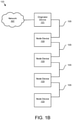
- Figure 1B is a schematic block diagram of the communication system 100 of Figure 1A .
- the serial network 105 comprises a plurality of point-to-point connections between node devices 103 and/or the originator device 101.
- Figure 1C is a schematic diagram of a node device 103 and serial network 105.
- the serial network 105 connects to the node device 103 via a node connection 111.
- the node connection 111 comprises a node connection 111d in physical communication with the serial network 105 and a node connection 111c in physical communication with node device 103.
- the node connection 111 may be a connector.
- the node connection 111 may be cable connection point assembly.
- the serial network 105 includes a plurality of lines 119.
- the lines 119 may include serial communication lines, power lines, bus lines, and the like.
- a select line 115 may locate node devices 103 on the serial network 105. In one embodiment, the select line 115 commissions node devices 103 for communication..
- the node connection 111 comprises two select line connections 113-1/2 for the select line 115 of the serial network 105.
- One select line connection 113-1/2 connects to an input line 121 and the other select line connection 113-1/2 connects to an output line 123 for communication hardware 125.
- the communication hardware 125 may propagate the selection signal according to the protocol for the serial network 105.
- the select line 115 is broken at the node connection 111.
- An asserted selection signal may be received on an upstream select line 115a connected to the input line 121 by a first node device 103.
- the first node device 103 accesses the lines 119 and determines if the first node device 103 is to send and/or receive communications via the lines 119. If the first node device 103 is to send and/or receive communications via the lines 119, the first node device 103 de-asserts the output a downstream select line 115b for a subsequent node device 103 and communicates via the lines 119.
- the first node device 103 If the first node device 103 is not to send and/or receive communications via the lines 119, the first node device 103 asserts the output line 123 connected to the downstream select line 115b for the subsequent node device 103. A subsequent node device 103 accesses the lines 119 to determine whether the subsequent node device 103 is to send and/or receive communications via the lines 119. Thus, the select line 115 determines which node device 103 communicates via the lines 119.
- the serial network 105 and cable thereof could only be oriented at each node device 103 in a single direction so that one select line connection 113 always connected to the input line 121 and the other select line connection 113 always connected to the output line 121.
- an upstream serial network 105 from the direction of the originator device 101 would always be oriented to the left of the node device 103.
- the upstream serial network 105 from the direction of the originator device 101 would always be oriented to the right of the node device 103.
- adding an additional row of node devices 103 required that the serial network 105 be doubled back before starting the additional row.
- the serial network 105 is oriented from upstream on the left to downstream on the right, after the serial network 105 connects the first row of node devices 103 from left to right, the serial network 105 must double back to start the additional row of network devices 103 from left to right.
- the length of the serial network 105 is increased and the space required by the serial network 105 is enlarged.
- a single serial network 105 may connect two rows of node devices 103 in multiple directions.
- the serial network 105 may connect to rows of node devices 103 in both a left to right direction and also a right to left direction.
- the serial network 105 may connect to rows of node devices 103 in both a top-to-bottom direction and also a bottom-to-top direction.
- the embodiments reduce the length and space requirement of the serial network 105 when connecting multiple rows of node devices 103.
- the node device 103 may include a bus direction module 109 that configures a first select line connection 113 for the input line 121 and a second select line connection 113 for the output line 123 in response to the selection event. At least a portion of the bus direction module 109 comprises one or more of hardware and executable code, the executable code stored on a memory as will be described hereafter
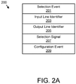
- FIG. 2A is a schematic block diagram of bus data 200.
- the bus data 200 may be used to configure the select line connections 113.
- the bus data 200 may be organized as a data structure in a memory.
- the bus data 200 includes a selection event 201, an input line identifier 203, an output line identifier 205, a selection signal 207, and a configuration event 209.
- the selection event 201 may be receiving the selection signal 207 at one of the select line connections 113.
- the selection event 201 may be a manual switch 303 that connects the first select line connection 113 to the input line 121 and the second select line connection 113 to the output line 123.
- the selection event 201 is receiving a point-to-point cable that connects the first select line connection 113 to the input line 121 and the second select line connection 113 to the output line 123.
- the input line identifier 203 may identify a port on the communication hardware 125 as the input line 121.
- the output line identifier 205 may identify a port on the communication hardware 125 as the output line 123.
- the input line identifier 203 and the output line identifier 205 may be used to configure the first select line connection 113 for the input line 121 and the second select line connection 113 for the output line 123.
- the selection signal 207 may originate at the originator device 101.
- a node device 103 may receive the selection signal 207 at the upstream select line 115a.
- a node device 103 may propagate the selection signal 207 at the downstream select line 115b.
- the configuration event 209 may cause the embodiments to configure the bus direction module 109 and/or node device 103.
- the configuration event 209 is determined by the originator device 101.
- the configuration event 209 may be determined by the network 107 and/or one or more node devices 103.
- the configuration event 209 may be selected from the group consisting of a power on, a reset, and a test.
- Figure 2B is a schematic diagram of a node connection 111a.
- the node connection 111a includes the select line 115 connected to the first select line connection 113a, the select line 115 connected to the second select line connection 113b, and a plurality of lines 119.
- the lines 119 include a negative network power 221b, a positive Ethernet 223a, a negative Ethernet 223b, a positive network power 221a, a positive control power 225a, and a negative control power 225b.
- the Ethernet 223 provides communications for the device nodes 103.
- a device node 103 accesses the Ethernet 223 if the select line 115 is asserted.
- the positive network power 221a may provide regulated power for the node device 103.
- the negative network power 221b may provide negative and/or return regulated power for the node device 103.
- the positive control power 225a may provide unregulated power for the node device 103.
- the negative control power 225b may provide unregulated negative and/or return power for the node device 103.
- Figure 2C is a schematic diagram of a node connection 111b.
- the select line 115 connected to the first selection line connection 113a and the select line 115 connected to the second selection line connection 113b are switched relative to the first node connection 111a of Figure 2B .
- Figure 2D is a schematic diagram of node connections 111a/b.
- node connections 111a/b on the serial network 105 have left and right select lines 115 connected to opposite configurations of first select line connections 113a and second select line connections 113b.
- serial network 105 may connect to a first row of node devices 103 in a left-to-right direction and a second row of node devices 103 in a right-to-left direction.
- Figure 3A is a schematic diagram of a node device 103.
- the bus direction module 109 listens at both the select line connections 113/select lines 115 for a selection signal 207.
- the selection event 201 is receiving a selection signal 207 at one of the select line connections 113/select lines 115.
- the bus direction module 109 configures a first select line connection 113a for the input line 121 and a second select line connection 113b for the output line 123.
- the node device 103 may support a right-to-left direction of serial network 105 connections as shown while another node device 103 supports a left-to-right direction
- Embodiments of the bus direction module 109 for the node device 103 of Figure 3A are shown in Figures 4A-C .
- Figure 3B is a schematic diagram of a node device 103.
- the bus direction module 109 comprises a manual switch 303.
- Figures 3F-J illustrate embodiments of the manual switch 303.
- the selection event 201 is the manual switch 303 that connects the first select line connection 113a to the input line 121 and the second select line connection 113b to the output line 123 as shown.
- the depicted node device 103 may support a left-to-right direction of serial network 105 connections.
- the manual switch 303 is disposed in the node device 103.
- the manual switch 303 may be disposed in the node connection 111.
- the manual switch 303 may be disposed in the node connection 111d in physical communication with the serial network 105.
- the manual switch 303 may be disposed in the node connection 111c in physical communication with node device 103.
- Figure 3C is a schematic diagram of the node device 103 of Figure 3B .
- the positions of the first select line connection 113a and the second select line connection 113b are reversed by the manual switch 303.
- the depicted node device 103 may support a right-to-left direction of serial network 105 connections.
- Figure 3D is a schematic diagram of a node device 103 and point-to-point cables 305.
- the serial network 105 of Figure 1B comprises the point-to-point cables 305.
- Each point-to-point cable 305 connects at least two node devices 103.
- a first point-to-point cable 305a with a node connection 111-1 connects the first select line connection 113a to the input line 121 and a second point-to-point cable 305b with a node connection 111-2 connects the second select line connection 113b to the output line 123.
- the node device 103 may support a left-to-right direction of serial network 105 connections.
- the bus direction module 109 may be embodied in the point-to-point cables 305a-b.
- Figure 3E is a schematic diagram of a node device 103 and point-to-point cables 305.
- the serial network 105 of Figure 1B comprises the two point-to-point cables 305a-b.
- Each point-to-point cable 305 connects at least two node devices 103.
- a first point-to-point cable 305a with a node connection 111-3 connects the first select line connection 113a to the input line 121 and a second point-to-point cable 305b with a node connection 111-4 connects the second select line connection 113b to the output line 123.
- the depicted node device 103 may support a right-to-left direction of serial network 105 connections.
- the bus direction module 109 may be embodied in the point-to-point cables 305a-b.
- FIG. 3F is a schematic diagram of a dual inline package (DIP) manual switch 303b or DIP switch 303b.
- a first switch connection 117a connects one select line connection 113-1 to the output line 123 and a second switch connection 117b connects the other select line connection 113-2 to the input line 121.
- FIG 3G is a schematic diagram of the DIP manual switch 303b.
- the first switch connection 117a and second switch connection 117b of Figure 3F are reversed.
- a first switch connection 117a connections the other select line connection 113-2 to the output line 123
- a second switch connection 117b connects the one select line connection 113-1 to the input line 121.
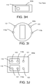
- FIG 3H is a schematic diagram of a manual switch 303b.
- a single switch 119 is shown.
- the single switch 119 may toggle both the first switch connection 117a and the second switch connection 117b of Figures 3F-G .
- Figure 3I is a schematic diagram of a rotary manual switch 303c or rotary switch 303c.
- the rotary manual switch 303c may toggle both the first switch connection 117a and the second switch connection 117b of Figures 3F-G .
- Figure 3J is a schematic diagram of a jumper manual switch 303a or jumper switch 303a.
- jumpers 118 connect one select line connection 113-1 to the output line 123 and the other select line connection 113-2 to the input line 121.
- Figure 3K is a schematic diagram of a node device 103.
- a first directional node connection 111d-1 in physical communication with the serial network 105 connects a left select line 115l with the input line 121 and connects a right select line 1 15r with the output line 123.
- the bus direction module 109 may be embodied in the first directional node connection 111d-1.
- the first directional node connection 111d-1 may be a left-to-right node connection manual switch 303.
- Figure 3L is a schematic diagram of a node device 103.
- a second directional node connection 111d-2 in physical communication with the serial network 105 connects a left select line 1151 with the output line 123 and connects a right select line 115r with the input line 121.
- the bus direction module 109 may be embodied in the second node connection 111d-2.
- the second directional node connection 111d-2 may be a right-to-left node connection manual switch 303.
- FIG 4A is a schematic diagram of a bus direction module 109.
- the bus direction module 109 includes a microcontroller 331, a plurality of resistors 333 and transistors 335 powered by the network power 221.
- the bus direction module 109 is connected to the two select line connections 113-1/2.
- the microcontroller 331 includes two signal inputs 337-1/2 and two signal outputs 339-1/2.
- the microcontroller 331 detects the selection signal 207 at one of the two signal inputs 337-1/2 and in response outputs the selection signal 207 at the other signal output 339-1/2 to propagate the selection signal 207. For example, if the selection signal 207 is detected at one signal input 337-1, the microcontroller 331 outputs the selection signal 207 at the other signal output 339-2. Thus, the selection signal 207 is propagated.
- FIG 4B is a schematic diagram of a bus direction module 109.
- the bus direction module 109 includes a microcontroller 331, a plurality of resistors 333, diodes 343, and transistors 335 powered by the network power 221 and the control power 225.
- the microcontroller 331 includes two bi-directional nodes 345-1/2. The microcontroller 331 may detect the selection signal 207 on one node 345-2 and output the selection signal 207 on the other node 345-1 if the selection signal 207 is propagated.
- Figure 4C is a schematic diagram of a bus direction module 109.
- the bus direction module 109 includes a processor 405, a memory 410, and communication hardware 125.
- the memory 410 may store code and data.
- the processor 405 may execute the code and process the data.
- the processor 405 may detect the selection signal 207 via the communication hardware 125 at one select line connection 113-1.
- the processor 405 may further output the selection signal 207 via the communication hardware 125 at the other select line connection 113-2 if the selection signal 207 is propagated.
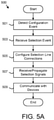
- Figure 5A is a schematic flow chart diagram of a communication method 500.
- the method 500 may configure the selection line connections 113 to support communication between the node devices 103 and the originator device 101.
- the method may be performed by the bus direction module 109, node device 103, and/or originator device 101.
- the method 500 starts, and in one embodiment, the bus direction module 109, node device 103, and/or originator device 101 detects 501 a configuration event 209.
- the configuration event 209 may be selected from the group consisting of a power on of the system 100, bus direction module 109, node device 103, and/or originator device 101, a reset of the system 100, bus direction module 109, node device 103, and/or originator device 101, and a test of the system 100, bus direction module 109, node device 103, and/or originator device 101.
- the originator device 101 may communicate the selection signal 207 via the select line 115.
- the selection signal 207 may be directed to each node device 103 in turn to configure the node device 103.
- the bus direction module 109 and/or node device 103 receives 503 the selection event 201.
- the selection event 201 is receiving the selection signal 207 at one of the select line connections 113 and/or select lines 115. Receiving the selection signal 207 is described in more detail in Figure 5B .
- the selection event 201 may be the manual switch 303 and/or a setting of the manual switch 303 as shown in Figures 3B-C .
- the selection event 201 is the installation of a first directional node connection 111d-1 or a second directional node connection 111d-2 as shown in Figures 3K-L .
- the selection event 201 is receiving point-to-point cables 305 that connect the first select line connection 113a to the input line 121 and the second select line connection 113b to the output line 123 as shown in Figures 3D-E .
- the bus direction module 109 configures 505 the first select line connection 113a for the input line 121 and the second select line connection 113b for the output line 123 in response to the selection event 201 as shown in Figure 3A .
- the bus direction module 109 electronically designates the first select line connection 113a and second select line connection 113b as shown in the embodiments of Figures 4A-B .
- the input line identifier 203 may be set to a port for the first select line connection 113a and the output line identifier 205 may be set to a port for the second select line connection 113b.
- the setting of the manual switch 303 may configure 505 the first select line connection 113a for the input line 121 and the second select line connection 113b for the output line 123 as shown in Figures 3B-C .
- the manual switch 303 may be selected from the group consisting of the jumper switch 303a, a DIP switch 303b, and a rotary switch 303c.
- the manual switch 303 is a connector selected from the group consisting of the left-to-right node connection 111d-1 and the right-to-left node connection 111d-2.
- the receiving of point-to-point cables 305 may be the selection event 201.
- the point-to-point cables 305 may connect the first select line connection 113a to the input line 121 and the second select line connection 113b to the output line 123 as shown in Figures 3D-E .
- the selection of the node connection 111 configures 505 the select line connections 113.
- the node connection 111 may be one of a first directional connection node 111d-1 that connects one select line connection 113-1 to the input line 121 and the other select line connection 113-2 to the output line 123 or a second directional connection node 111d-2 that connects the other select line connection 113-2 to the input line 121 and the one select line connection 113-1 to the output line 123.
- the bus direction module 109 and/or node device 103 may receive and/or propagate 507 the selection signals 207 using the configured select line connections 113. As a result, the node device 103 may communicate 509 with other node devices 103 and/or the originator device 101 and the method 500 ends.
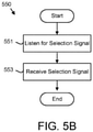
- Figure 5B is a schematic flow chart diagram of a selection method 550.
- the selection method 550 may electronically configure the first select line connection 113a for the input line 121 and the second select line connection 113b for the output line 123 in response to the selection event 201.
- the method 550 may be performed by the bus direction module 109.
- the bus direction module 109 may listen 551 at the select line connections 113 and/or select lines 115 for the selection signal 207.
- the bus direction module 109 further receives 553 the selection signal 207 at one of the select line connections 113 and/or select lines 115 as the selection event 201 and the method 550 ends.
- a serial network 105 may employ a select line 115 to locate node devices 103 on the serial network 105.
- the select line 115 may be broken at each node device 103, with an upstream select line 115a and the downstream select line 115b.
- only a single orientation of the serial network 105 could be employed at each node device 103 so that the upstream select line 115a was received at the input line 121 and the output line 123 was connected to the downstream select line 115b.
- the serial network 105 had to be doubled back to connect multiple rows of node devices 103.
Landscapes
- Engineering & Computer Science (AREA)
- Theoretical Computer Science (AREA)
- Physics & Mathematics (AREA)
- General Engineering & Computer Science (AREA)
- General Physics & Mathematics (AREA)
- Mathematical Physics (AREA)
- Computer Hardware Design (AREA)
- Automation & Control Theory (AREA)
- Small-Scale Networks (AREA)
Abstract
Description
- The subject matter disclosed herein relates to bus topology
- An apparatus for bi-directional bus topology is disclosed. The apparatus includes a node connection and a bidirectional module. The node connection includes two select line connections for a select line of a serial network. The select line is broken at the node connection. The bus direction module configures a first select line connection for an input line and a second select line connection for an output line in response to detecting a selection event. At least a portion of the bus direction module includes one or more of hardware and executable code, the executable code stored on a memory.
- A method for a bidirectional bus topology is also disclosed. The method detects a selection event at a node connection comprising two select line connections for a select line of a serial network. The select line is broken at the node connection. The method further configures a first select line connection for an input line and a second select line connection for an output line in response to detecting the selection event.
- A system for bidirectional bus topology is also disclosed. The system includes an originator device and a node device. The originator device originates a selection signal. The node device includes two select line connections for a select line of a serial network. The select line is broken at the node connection. The node device configures a first select line connection for an input line and a second select line connection for an output line in response to detecting a selection event of the selection signal. At least a portion of the originator device and the node device comprises one or more of hardware and executable code, the executable code stored on a memory.
- In order that the advantages of the embodiments of the invention will be readily understood, a more particular description of the embodiments briefly described above will be rendered by reference to specific embodiments that are illustrated in the appended drawings. Understanding that these drawings depict only some embodiments and are not therefore to be considered to be limiting of scope, the embodiments will be described and explained with additional specificity and detail through the use of the accompanying drawings, in which:
-
Figure 1A is a schematic block diagram of communication system according to an embodiment; -
Figure 1B is a schematic block diagram of communication system according to an alternate embodiment; -
Figure 1C is a schematic diagram of a node device and serial network according to an embodiment; -
Figure 2A is a schematic block diagram of bus data according to an embodiment; -
Figure 2B is a schematic diagram of a node connection according to an embodiment; -
Figure 2C is a schematic diagram of a node connection according to an alternate embodiment; -
Figure 2D is a schematic diagram of node connections according to an embodiment; -
Figure 3A is a schematic diagram of a node device according to an embodiment; -
Figure 3B is a schematic diagram of a node device and manual switch according to an embodiment; -
Figure 3C is a schematic diagram of a node device and manual switch according to an alternate embodiment, -
Figure 3D is a schematic diagram of a node device and point-to-point cable according to an embodiment; -
Figure 3E is a schematic diagram of a node device and point-to-point cable according to an alternate embodiment, -
Figure 3F is a schematic diagram of a manual switch according to an embodiment; -
Figure 3G is a schematic diagram of a manual switch according to an alternate embodiment; -
Figure 3H is a schematic diagram of a manual switch according to an alternate embodiment; -
Figure 3I is a schematic diagram of a manual switch according to an alternate embodiment; -
Figure 3J is a schematic diagram of a manual switch according to an alternate embodiment; -
Figure 3K is a schematic diagram of a node device according to an embodiment; -
Figure 3L is a schematic diagram of a node device according to an embodiment; -
Figure 4A is a schematic diagram of a bus direction module according to an embodiment; -
Figure 4B is a schematic diagram of a bus direction module according to an alternate embodiment; -
Figure 4C is a schematic block diagram of a bus direction module according to an alternate embodiment; -
Figure 5A is a schematic flow chart diagram of a communication method according to an embodiment; and -
Figure 5B is a schematic flow chart diagram of a selection method according to an embodiment. - Reference throughout this specification to "one embodiment," "an embodiment," or similar language means that a particular feature, structure, or characteristic described in connection with the embodiment is included in at least one embodiment. Thus, appearances of the phrases "in one embodiment," "in an embodiment," and similar language throughout this specification may, but do not necessarily, all refer to the same embodiment, but mean "one or more but not all embodiments" unless expressly specified otherwise. The terms "including," "comprising," "having," and variations thereof mean "including but not limited to" unless expressly specified otherwise. An enumerated listing of items does not imply that any or all of the items are mutually exclusive and/or mutually inclusive, unless expressly specified otherwise. The terms "a," "an," and "the" also refer to "one or more" unless expressly specified otherwise. The term "and/or" indicates embodiments of one or more of the listed elements, with "A and/or B" indicating embodiments of element A alone, element B alone, or elements A and B taken together.
- Furthermore, the described features, advantages, and characteristics of the embodiments may be combined in any suitable manner. One skilled in the relevant art will recognize that the embodiments may be practiced without one or more of the specific features or advantages of a particular embodiment. In other instances, additional features and advantages may be recognized in certain embodiments that may not be present in all embodiments.
- These features and advantages of the embodiments will become more fully apparent from the following description and appended claims or may be learned by the practice of embodiments as set forth hereinafter. As will be appreciated by one skilled in the art, aspects of the present invention may be embodied as a system, method, and/or computer program product. Accordingly, aspects of the present invention may take the form of an entirely hardware embodiment, an entirely software embodiment (including firmware, resident software, micro-code, etc.) or an embodiment combining software and hardware aspects that may all generally be referred to herein as a "circuit," "module," or "system." Furthermore, aspects of the present invention may take the form of a computer program product embodied in one or more computer readable medium(s) having program code embodied thereon.
- Many of the functional units described in this specification have been labeled as modules, in order to more particularly emphasize their implementation independence. For example, a module may be implemented as a hardware circuit comprising custom VLSI circuits or gate arrays, off-the-shelf semiconductors such as logic chips, transistors, or other discrete components. A module may also be implemented in programmable hardware devices such as field programmable gate arrays, programmable array logic, programmable logic devices or the like.
- Modules may also be implemented in software for execution by various types of processors. An identified module of program code may, for instance, comprise one or more physical or logical blocks of computer instructions which may, for instance, be organized as an object, procedure, or function. Nevertheless, the executables of an identified module need not be physically located together but may comprise disparate instructions stored in different locations which, when joined logically together, comprise the module and achieve the stated purpose for the module.
- Indeed, a module of program code may be a single instruction, or many instructions, and may even be distributed over several different code segments, among different programs, and across several memory devices. Similarly, operational data may be identified and illustrated herein within modules and may be embodied in any suitable form and organized within any suitable type of data structure. The operational data may be collected as a single data set or may be distributed over different locations including over different storage devices, and may exist, at least partially, merely as electronic signals on a system or network. Where a module or portions of a module are implemented in software, the program code may be stored and/or propagated on in one or more computer readable medium(s).
- The computer readable medium may be a tangible computer readable storage medium storing the program code. The computer readable storage medium may be, for example, but not limited to, an electronic, magnetic, optical, electromagnetic, infrared, holographic, micromechanical, or semiconductor system, apparatus, or device, or any suitable combination of the foregoing.
- More specific examples of the computer readable storage medium may include but are not limited to a portable computer diskette, a hard disk, a random access memory (RAM), a read-only memory (ROM), an erasable programmable read-only memory (EPROM or Flash memory), a portable compact disc read-only memory (CD-ROM), a digital versatile disc (DVD), an optical storage device, a magnetic storage device, a holographic storage medium, a micromechanical storage device, or any suitable combination of the foregoing. In the context of this document, a computer readable storage medium may be any tangible medium that can contain, and/or store program code for use by and/or in connection with an instruction execution system, apparatus, or device.
- The computer readable medium may also be a computer readable signal medium. A computer readable signal medium may include a propagated data signal with program code embodied therein, for example, in baseband or as part of a carrier wave. Such a propagated signal may take any of a variety of forms, including, but not limited to, electrical, electro-magnetic, magnetic, optical, or any suitable combination thereof A computer readable signal medium may be any computer readable medium that is not a computer readable storage medium and that can communicate, propagate, or transport program code for use by or in connection with an instruction execution system, apparatus, or device. Program code embodied on a computer readable signal medium may be transmitted using any appropriate medium, including but not limited to wire-line, optical fiber, Radio Frequency (RF), or the like, or any suitable combination of the foregoing
- In one embodiment, the computer readable medium may comprise a combination of one or more computer readable storage mediums and one or more computer readable signal mediums. For example, program code may be both propagated as an electro-magnetic signal through a fiber optic cable for execution by a processor and stored on RAM storage device for execution by the processor.
- Program code for carrying out operations for aspects of the present invention may be written in any combination of one or more programming languages, including an object oriented programming language such as Python, Ruby, R, Java, Java Script, Smalltalk, C++, C sharp, Lisp, Clojure, PHP or the like and conventional procedural programming languages, such as the "C" programming language or similar programming languages. The program code may execute entirely on the user's computer, partly on the user's computer, as a stand-alone software package, partly on the user's computer and partly on a remote computer or entirely on the remote computer or server. In the latter scenario, the remote computer may be connected to the user's computer through any type of network, including a local area network (LAN) or a wide area network (WAN), or the connection may be made to an external computer (for example, through the Internet using an Internet Service Provider). The computer program product may be shared, simultaneously serving multiple customers in a flexible, automated fashion.
- The computer program product may be integrated into a client, server and network environment by providing for the computer program product to coexist with applications, operating systems and network operating systems software and then installing the computer program product on the clients and servers in the environment where the computer program product will function. In one embodiment software is identified on the clients and servers including the network operating system where the computer program product will be deployed that are required by the computer program product or that work in conjunction with the computer program product. This includes the network operating system that is software that enhances a basic operating system by adding networking features.
- Furthermore, the described features, structures, or characteristics of the embodiments may be combined in any suitable manner. In the following description, numerous specific details are provided, such as examples of programming, software modules, user selections, network transactions, database queries, database structures, hardware modules, hardware circuits, hardware chips, etc., to provide a thorough understanding of embodiments. One skilled in the relevant art will recognize, however, that embodiments may be practiced without one or more of the specific details, or with other methods, components, materials, and so forth. In other instances, well-known structures, materials, or operations are not shown or described in detail to avoid obscuring aspects of an embodiment.
- The embodiments may transmit data between electronic devices. The embodiments may further convert the data from a first format to a second format, including converting the data from a non-standard format to a standard format and/or converting the data from the standard format to a non-standard format. The embodiments may modify, update, and/or process the data. The embodiments may store the received, converted, modified, updated, and/or processed data. The embodiments may provide remote access to the data including the updated data. The embodiments may make the data and/or updated data available in real time. The embodiments may generate and transmit a message based on the data and/or updated data in real time. The embodiments may securely communicate encrypted data. The embodiments may organize data for efficient validation. In addition, the embodiments may validate the data in response to an action and/or a lack of an action.
- Aspects of the embodiments are described below with reference to schematic flowchart diagrams and/or schematic block diagrams of methods, apparatuses, systems, and computer program products according to embodiments of the invention. It will be understood that each block of the schematic flowchart diagrams and/or schematic block diagrams, and combinations of blocks in the schematic flowchart diagrams and/or schematic block diagrams, can be implemented by program code. The program code may be provided to a processor of a general purpose computer, special purpose computer, sequencer, or other programmable data processing apparatus to produce a machine, such that the instructions, which execute via the processor of the computer or other programmable data processing apparatus, create means for implementing the functions/acts specified in the schematic flowchart diagrams and/or schematic block diagrams block or blocks.
- The program code may also be stored in a computer readable medium that can direct a computer, other programmable data processing apparatus, or other devices to function in a particular manner, such that the instructions stored in the computer readable medium produce an article of manufacture including instructions which implement the function/act specified in the schematic flowchart diagrams and/or schematic block diagrams block or blocks.
- The program code may also be loaded onto a computer, other programmable data processing apparatus, or other devices to cause a series of operational steps to be performed on the computer, other programmable apparatus or other devices to produce a computer implemented process such that the program code which executed on the computer or other programmable apparatus provide processes for implementing the functions/acts specified in the flowchart and/or block diagram block or blocks.
- The schematic flowchart diagrams and/or schematic block diagrams in the Figures illustrate the architecture, functionality, and operation of possible implementations of apparatuses, systems, methods and computer program products according to various embodiments of the present invention. In this regard, each block in the schematic flowchart diagrams and/or schematic block diagrams may represent a module, segment, or portion of code, which comprises one or more executable instructions of the program code for implementing the specified logical function(s).
- It should also be noted that, in some alternative implementations, the functions noted in the block may occur out of the order noted in the Figures. For example, two blocks shown in succession may, in fact, be executed substantially concurrently, or the blocks may sometimes be executed in the reverse order, depending upon the functionality involved. Other steps and methods may be conceived that are equivalent in function, logic, or effect to one or more blocks, or portions thereof, of the illustrated Figures.
- Although various arrow types and line types may be employed in the flowchart and/or block diagrams, they are understood not to limit the scope of the corresponding embodiments. Indeed, some arrows or other connectors may be used to indicate only the logical flow of the depicted embodiment. For instance, an arrow may indicate a waiting or monitoring period of unspecified duration between enumerated steps of the depicted embodiment. It will also be noted that each block of the block diagrams and/or flowchart diagrams, and combinations of blocks in the block diagrams and/or flowchart diagrams, can be implemented by special purpose hardware-based systems that perform the specified functions or acts, or combinations of special purpose hardware and program code.
- The description of elements in each figure may refer to elements of proceeding figures. Like numbers refer to like elements in all figures, including alternate embodiments of like elements.
-
Figure 1A is a schematic block diagram ofcommunication system 100. Thecommunication system 100 supports communications among a plurality ofnode devices 103 and anoriginator device 101. In one embodiment, thecommunication system 100 supports communications between thenode devices 103 and/ororiginator device 101 and anetwork 107. - The
node devices 103 and/ororiginator device 101 may be controls, displays, sensors, indicators, and the like. In one embodiment, thenode devices 103 and/ororiginator device 101 are disposed within industrial automation equipment such as a motor controller. Thenode devices 103 and theoriginator device 101 are connected via aserial network 105. In the depicted embodiment, theserial network 105 comprises a single cable. Theserial network 105 provides an efficient physical connection between thenode devices 103 and/or theoriginator device 101. For example, theserial network 105 may connect a plurality ofcontrol node devices 103 to thenetwork 107. The use of theserial network 105 reduces point-to-point hardwiring of thenode devices 103, and so reduces the cost of communications between thenode devices 103 and/ororiginator device 101 in thenetwork 107. -
Figure 1B is a schematic block diagram of thecommunication system 100 ofFigure 1A . In the depicted embodiment, theserial network 105 comprises a plurality of point-to-point connections betweennode devices 103 and/or theoriginator device 101. -
Figure 1C is a schematic diagram of anode device 103 andserial network 105. In the depicted embodiment, theserial network 105 connects to thenode device 103 via anode connection 111. Thenode connection 111 comprises anode connection 111d in physical communication with theserial network 105 and anode connection 111c in physical communication withnode device 103. Thenode connection 111 may be a connector. In addition, thenode connection 111 may be cable connection point assembly. - The
serial network 105 includes a plurality oflines 119. Thelines 119 may include serial communication lines, power lines, bus lines, and the like. Aselect line 115 may locatenode devices 103 on theserial network 105. In one embodiment, theselect line 115commissions node devices 103 for communication.. - The
node connection 111 comprises two select line connections 113-1/2 for theselect line 115 of theserial network 105. One select line connection 113-1/2 connects to aninput line 121 and the other select line connection 113-1/2 connects to anoutput line 123 forcommunication hardware 125. Thecommunication hardware 125 may propagate the selection signal according to the protocol for theserial network 105. - As shown, the
select line 115 is broken at thenode connection 111. An asserted selection signal may be received on an upstreamselect line 115a connected to theinput line 121 by afirst node device 103. Thefirst node device 103 accesses thelines 119 and determines if thefirst node device 103 is to send and/or receive communications via thelines 119. If thefirst node device 103 is to send and/or receive communications via thelines 119, thefirst node device 103 de-asserts the output a downstreamselect line 115b for asubsequent node device 103 and communicates via thelines 119. If thefirst node device 103 is not to send and/or receive communications via thelines 119, thefirst node device 103 asserts theoutput line 123 connected to the downstreamselect line 115b for thesubsequent node device 103. Asubsequent node device 103 accesses thelines 119 to determine whether thesubsequent node device 103 is to send and/or receive communications via thelines 119. Thus, theselect line 115 determines whichnode device 103 communicates via thelines 119. - Because the
select line 115 at eachnode device 103 has the upstreamselect line 115a and the downstreamselect line 115b, in the past, theserial network 105 and cable thereof could only be oriented at eachnode device 103 in a single direction so that one select line connection 113 always connected to theinput line 121 and the other select line connection 113 always connected to theoutput line 121. For example, an upstreamserial network 105 from the direction of theoriginator device 101 would always be oriented to the left of thenode device 103. Alternatively, the upstreamserial network 105 from the direction of theoriginator device 101 would always be oriented to the right of thenode device 103. - As a result, adding an additional row of
node devices 103 required that theserial network 105 be doubled back before starting the additional row. For example, if theserial network 105 is oriented from upstream on the left to downstream on the right, after theserial network 105 connects the first row ofnode devices 103 from left to right, theserial network 105 must double back to start the additional row ofnetwork devices 103 from left to right. As a result, the length of theserial network 105 is increased and the space required by theserial network 105 is enlarged. - The embodiments described herein configure a first select line connection 113 of the select line connections 113-1/2 for the
input line 121 and the second select line connection 113 of the select line connections 113-1/2 for theoutput line 123 in response to a selection event. As a result, a singleserial network 105 may connect two rows ofnode devices 103 in multiple directions. For example, theserial network 105 may connect to rows ofnode devices 103 in both a left to right direction and also a right to left direction. In addition, theserial network 105 may connect to rows ofnode devices 103 in both a top-to-bottom direction and also a bottom-to-top direction. Thus, the embodiments reduce the length and space requirement of theserial network 105 when connecting multiple rows ofnode devices 103. - The
node device 103 may include abus direction module 109 that configures a first select line connection 113 for theinput line 121 and a second select line connection 113 for theoutput line 123 in response to the selection event. At least a portion of thebus direction module 109 comprises one or more of hardware and executable code, the executable code stored on a memory as will be described hereafter -
Figure 2A is a schematic block diagram ofbus data 200. Thebus data 200 may be used to configure the select line connections 113. Thebus data 200 may be organized as a data structure in a memory. In the depicted embodiment, thebus data 200 includes aselection event 201, aninput line identifier 203, an output line identifier 205, aselection signal 207, and aconfiguration event 209. - The
selection event 201 may be receiving theselection signal 207 at one of the select line connections 113. In addition, theselection event 201 may be amanual switch 303 that connects the first select line connection 113 to theinput line 121 and the second select line connection 113 to theoutput line 123. In a certain embodiment, theselection event 201 is receiving a point-to-point cable that connects the first select line connection 113 to theinput line 121 and the second select line connection 113 to theoutput line 123. - The
input line identifier 203 may identify a port on thecommunication hardware 125 as theinput line 121. The output line identifier 205 may identify a port on thecommunication hardware 125 as theoutput line 123. Theinput line identifier 203 and the output line identifier 205 may be used to configure the first select line connection 113 for theinput line 121 and the second select line connection 113 for theoutput line 123. - The
selection signal 207 may originate at theoriginator device 101. Anode device 103 may receive theselection signal 207 at the upstreamselect line 115a. In addition, anode device 103 may propagate theselection signal 207 at the downstreamselect line 115b. - The
configuration event 209 may cause the embodiments to configure thebus direction module 109 and/ornode device 103. In one embodiment, theconfiguration event 209 is determined by theoriginator device 101. In addition, theconfiguration event 209 may be determined by thenetwork 107 and/or one ormore node devices 103. Theconfiguration event 209 may be selected from the group consisting of a power on, a reset, and a test. -
Figure 2B is a schematic diagram of anode connection 111a. In the depicted embodiment, thenode connection 111a includes theselect line 115 connected to the firstselect line connection 113a, theselect line 115 connected to the secondselect line connection 113b, and a plurality oflines 119. In one embodiment, thelines 119 include anegative network power 221b, apositive Ethernet 223a, anegative Ethernet 223b, apositive network power 221a, apositive control power 225a, and anegative control power 225b. The Ethernet 223 provides communications for thedevice nodes 103. In one embodiment, adevice node 103 accesses the Ethernet 223 if theselect line 115 is asserted. - The
positive network power 221a may provide regulated power for thenode device 103. Thenegative network power 221b may provide negative and/or return regulated power for thenode device 103. Thepositive control power 225a may provide unregulated power for thenode device 103. Thenegative control power 225b may provide unregulated negative and/or return power for thenode device 103. -
Figure 2C is a schematic diagram of anode connection 111b. In the depicted embodiment, theselect line 115 connected to the firstselection line connection 113a and theselect line 115 connected to the secondselection line connection 113b are switched relative to thefirst node connection 111a ofFigure 2B . -
Figure 2D is a schematic diagram ofnode connections 111a/b. In the depicted embodiment,node connections 111a/b on theserial network 105 have left and rightselect lines 115 connected to opposite configurations of firstselect line connections 113a and secondselect line connections 113b. As a result,serial network 105 may connect to a first row ofnode devices 103 in a left-to-right direction and a second row ofnode devices 103 in a right-to-left direction. -
Figure 3A is a schematic diagram of anode device 103. In the depicted embodiment, thebus direction module 109 listens at both the select line connections 113/select lines 115 for aselection signal 207. Theselection event 201 is receiving aselection signal 207 at one of the select line connections 113/select lines 115. In response to receiving theselection signal 207, thebus direction module 109 configures a firstselect line connection 113a for theinput line 121 and a secondselect line connection 113b for theoutput line 123. As a result, thenode device 103 may support a right-to-left direction ofserial network 105 connections as shown while anothernode device 103 supports a left-to-right direction Embodiments of thebus direction module 109 for thenode device 103 ofFigure 3A are shown inFigures 4A-C . -
Figure 3B is a schematic diagram of anode device 103. In the depicted embodiment, thebus direction module 109 comprises amanual switch 303.Figures 3F-J illustrate embodiments of themanual switch 303. In one embodiment, theselection event 201 is themanual switch 303 that connects the firstselect line connection 113a to theinput line 121 and the secondselect line connection 113b to theoutput line 123 as shown. As a result, the depictednode device 103 may support a left-to-right direction ofserial network 105 connections. - In one embodiment, the
manual switch 303 is disposed in thenode device 103. Alternatively, themanual switch 303 may be disposed in thenode connection 111. Themanual switch 303 may be disposed in thenode connection 111d in physical communication with theserial network 105. Alternatively, themanual switch 303 may be disposed in thenode connection 111c in physical communication withnode device 103. -
Figure 3C is a schematic diagram of thenode device 103 ofFigure 3B . In the depicted embodiment, the positions of the firstselect line connection 113a and the secondselect line connection 113b are reversed by themanual switch 303. As a result, the depictednode device 103 may support a right-to-left direction ofserial network 105 connections. -
Figure 3D is a schematic diagram of anode device 103 and point-to-point cables 305. In the depicted embodiment, theserial network 105 ofFigure 1B comprises the point-to-point cables 305. Each point-to-point cable 305 connects at least twonode devices 103. A first point-to-point cable 305a with a node connection 111-1 connects the firstselect line connection 113a to theinput line 121 and a second point-to-point cable 305b with a node connection 111-2 connects the secondselect line connection 113b to theoutput line 123. As a result, thenode device 103 may support a left-to-right direction ofserial network 105 connections. Thebus direction module 109 may be embodied in the point-to-point cables 305a-b. -
Figure 3E is a schematic diagram of anode device 103 and point-to-point cables 305. In the depicted embodiment, theserial network 105 ofFigure 1B comprises the two point-to-point cables 305a-b. Each point-to-point cable 305 connects at least twonode devices 103. A first point-to-point cable 305a with a node connection 111-3 connects the firstselect line connection 113a to theinput line 121 and a second point-to-point cable 305b with a node connection 111-4 connects the secondselect line connection 113b to theoutput line 123. As a result, the depictednode device 103 may support a right-to-left direction ofserial network 105 connections. Thebus direction module 109 may be embodied in the point-to-point cables 305a-b. -
Figure 3F is a schematic diagram of a dual inline package (DIP)manual switch 303b orDIP switch 303b. In the depicted embodiment, afirst switch connection 117a connects one select line connection 113-1 to theoutput line 123 and asecond switch connection 117b connects the other select line connection 113-2 to theinput line 121. -
Figure 3G is a schematic diagram of the DIPmanual switch 303b. In the depicted embodiment, thefirst switch connection 117a andsecond switch connection 117b ofFigure 3F are reversed. As a result, afirst switch connection 117a connections the other select line connection 113-2 to theoutput line 123 and asecond switch connection 117b connects the one select line connection 113-1 to theinput line 121. -
Figure 3H is a schematic diagram of amanual switch 303b. In the depicted embodiment, asingle switch 119 is shown. Thesingle switch 119 may toggle both thefirst switch connection 117a and thesecond switch connection 117b ofFigures 3F-G . -
Figure 3I is a schematic diagram of a rotarymanual switch 303c orrotary switch 303c. The rotarymanual switch 303c may toggle both thefirst switch connection 117a and thesecond switch connection 117b ofFigures 3F-G . -
Figure 3J is a schematic diagram of a jumpermanual switch 303a orjumper switch 303a. In the depicted embodiment,jumpers 118 connect one select line connection 113-1 to theoutput line 123 and the other select line connection 113-2 to theinput line 121. -
Figure 3K is a schematic diagram of anode device 103. In the depicted embodiment, a firstdirectional node connection 111d-1 in physical communication with theserial network 105 connects a left select line 115l with theinput line 121 and connects a rightselect line 1 15r with theoutput line 123. Thebus direction module 109 may be embodied in the firstdirectional node connection 111d-1. The firstdirectional node connection 111d-1 may be a left-to-right node connectionmanual switch 303. -
Figure 3L is a schematic diagram of anode device 103. In the depicted embodiment, a seconddirectional node connection 111d-2 in physical communication with theserial network 105 connects a leftselect line 1151 with theoutput line 123 and connects a rightselect line 115r with theinput line 121. Thebus direction module 109 may be embodied in thesecond node connection 111d-2. The seconddirectional node connection 111d-2 may be a right-to-left node connectionmanual switch 303. -
Figure 4A is a schematic diagram of abus direction module 109. In the depicted embodiment, thebus direction module 109 includes amicrocontroller 331, a plurality ofresistors 333 andtransistors 335 powered by the network power 221. Thebus direction module 109 is connected to the two select line connections 113-1/2. Themicrocontroller 331 includes two signal inputs 337-1/2 and two signal outputs 339-1/2. Themicrocontroller 331 detects theselection signal 207 at one of the two signal inputs 337-1/2 and in response outputs theselection signal 207 at the other signal output 339-1/2 to propagate theselection signal 207. For example, if theselection signal 207 is detected at one signal input 337-1, themicrocontroller 331 outputs theselection signal 207 at the other signal output 339-2. Thus, theselection signal 207 is propagated. -
Figure 4B is a schematic diagram of abus direction module 109. Thebus direction module 109 includes amicrocontroller 331, a plurality ofresistors 333,diodes 343, andtransistors 335 powered by the network power 221 and the control power 225. Themicrocontroller 331 includes two bi-directional nodes 345-1/2. Themicrocontroller 331 may detect theselection signal 207 on one node 345-2 and output theselection signal 207 on the other node 345-1 if theselection signal 207 is propagated. -
Figure 4C is a schematic diagram of abus direction module 109. In the depicted embodiment, thebus direction module 109 includes aprocessor 405, amemory 410, andcommunication hardware 125. Thememory 410 may store code and data. Theprocessor 405 may execute the code and process the data. Theprocessor 405 may detect theselection signal 207 via thecommunication hardware 125 at one select line connection 113-1. Theprocessor 405 may further output theselection signal 207 via thecommunication hardware 125 at the other select line connection 113-2 if theselection signal 207 is propagated. -
Figure 5A is a schematic flow chart diagram of acommunication method 500. Themethod 500 may configure the selection line connections 113 to support communication between thenode devices 103 and theoriginator device 101. The method may be performed by thebus direction module 109,node device 103, and/ororiginator device 101. - The
method 500 starts, and in one embodiment, thebus direction module 109,node device 103, and/ororiginator device 101 detects 501 aconfiguration event 209. Theconfiguration event 209 may be selected from the group consisting of a power on of thesystem 100,bus direction module 109,node device 103, and/ororiginator device 101, a reset of thesystem 100,bus direction module 109,node device 103, and/ororiginator device 101, and a test of thesystem 100,bus direction module 109,node device 103, and/ororiginator device 101. - In one embodiment, in response to the
configuration event 209, theoriginator device 101 may communicate theselection signal 207 via theselect line 115. For example, theselection signal 207 may be directed to eachnode device 103 in turn to configure thenode device 103. - The
bus direction module 109 and/ornode device 103 receives 503 theselection event 201. In one embodiment, theselection event 201 is receiving theselection signal 207 at one of the select line connections 113 and/orselect lines 115. Receiving theselection signal 207 is described in more detail inFigure 5B . - In addition, the
selection event 201 may be themanual switch 303 and/or a setting of themanual switch 303 as shown inFigures 3B-C . In one embodiment, theselection event 201 is the installation of a firstdirectional node connection 111d-1 or a seconddirectional node connection 111d-2 as shown inFigures 3K-L . In a certain embodiment, theselection event 201 is receiving point-to-point cables 305 that connect the firstselect line connection 113a to theinput line 121 and the secondselect line connection 113b to theoutput line 123 as shown inFigures 3D-E . - The
bus direction module 109 configures 505 the firstselect line connection 113a for theinput line 121 and the secondselect line connection 113b for theoutput line 123 in response to theselection event 201 as shown inFigure 3A . In one embodiment, thebus direction module 109 electronically designates the firstselect line connection 113a and secondselect line connection 113b as shown in the embodiments ofFigures 4A-B . For example, theinput line identifier 203 may be set to a port for the firstselect line connection 113a and the output line identifier 205 may be set to a port for the secondselect line connection 113b. - In addition, the setting of the
manual switch 303 may configure 505 the firstselect line connection 113a for theinput line 121 and the secondselect line connection 113b for theoutput line 123 as shown inFigures 3B-C . Themanual switch 303 may be selected from the group consisting of thejumper switch 303a, aDIP switch 303b, and arotary switch 303c. In a certain embodiment, themanual switch 303 is a connector selected from the group consisting of the left-to-right node connection 111d-1 and the right-to-leftnode connection 111d-2. - The receiving of point-to-point cables 305 may be the
selection event 201. The point-to-point cables 305 may connect the firstselect line connection 113a to theinput line 121 and the secondselect line connection 113b to theoutput line 123 as shown inFigures 3D-E . - In one embodiment, the selection of the
node connection 111 configures 505 the select line connections 113. Thenode connection 111 may be one of a firstdirectional connection node 111d-1 that connects one select line connection 113-1 to theinput line 121 and the other select line connection 113-2 to theoutput line 123 or a seconddirectional connection node 111d-2 that connects the other select line connection 113-2 to theinput line 121 and the one select line connection 113-1 to theoutput line 123. - The
bus direction module 109 and/ornode device 103 may receive and/or propagate 507 the selection signals 207 using the configured select line connections 113. As a result, thenode device 103 may communicate 509 withother node devices 103 and/or theoriginator device 101 and themethod 500 ends. -
Figure 5B is a schematic flow chart diagram of aselection method 550. Theselection method 550 may electronically configure the firstselect line connection 113a for theinput line 121 and the secondselect line connection 113b for theoutput line 123 in response to theselection event 201. Themethod 550 may be performed by thebus direction module 109. - The
bus direction module 109 may listen 551 at the select line connections 113 and/orselect lines 115 for theselection signal 207. Thebus direction module 109 further receives 553 theselection signal 207 at one of the select line connections 113 and/orselect lines 115 as theselection event 201 and themethod 550 ends. - A
serial network 105 may employ aselect line 115 to locatenode devices 103 on theserial network 105. Theselect line 115 may be broken at eachnode device 103, with an upstreamselect line 115a and the downstreamselect line 115b. In the past, only a single orientation of theserial network 105 could be employed at eachnode device 103 so that the upstreamselect line 115a was received at theinput line 121 and theoutput line 123 was connected to the downstreamselect line 115b. As a result, theserial network 105 had to be doubled back to connect multiple rows ofnode devices 103.
Claims (15)
- An apparatus comprising:a node connection comprising two select line connections for a select line of a serial network, wherein the select line is broken at the node connection;a bus direction module that configures a first select line connection for an input line and a second select line connection for an output line in response to detecting a selection event;wherein at least a portion of the bus direction module comprises one or more of hardware and executable code, the executable code stored on a memory.
- The apparatus of claim 1, wherein the bus direction module listens at the select line connections for a selection signal and the selection event is receiving the selection signal at one of the select line connections.
- The apparatus of claim 2, wherein the selection signal originates at an originator device in response to a configuration event selected from the group consisting of a power on, a reset, and a test.
- The apparatus of one of claims 1 to 3, wherein the selection event is a manual switch that connects the first select line connection to the input line and the second select line connection to the output line.
- The apparatus of claim 4, at least one of:wherein the manual switch is a node connection selected from the group consisting of a left-to-right node connection and a right-to-left node connection;wherein the manual switch is selected from the group consisting of a jumper, a dual inline package (DIP) switch, and a rotary switch; andwherein the manual switch is disposed in a node device.
- The apparatus of one of claims 1 to 5, at least one of:wherein the selection event is receiving point-to-point cables that connect the first select line connection to the input line and the second select line connection to the output line; andwherein the node connection is one of a first directional connection node that connects one select line connection to the input line and the other select line connection to the output line or a second directional connection node that connects the other select line connection to the input line and the one select line connection to the output line.
- A method comprising:detecting a selection event at a node connection comprising two select line connections for a select line of a serial network, wherein the select line is broken at the node connection; andconfiguring a first select line connection for an input line and a second select line connection for an output line in response to detecting the selection event.
- The method of claim 7, the method further comprising listening at the select line connections for a selection signal and wherein the selection event is receiving the selection signal at one of the select line connections.
- The method of claim 8, wherein the selection signal originates at an originator device in response to a configuration event selected from the group consisting of a power on, a reset, and a test.
- The method of one of claims 7 to 9, wherein the selection event is a manual switch that connects the first select line connection to the input line and the second select line connection to the output line.
- The method of claim 10, wherein the manual switch is a node connection selected from the group consisting of a left-to-right node connection and a right-to-left node connection.
- The method of claim 10, at least one of:wherein the manual switch is selected from the group consisting of a jumper, a dual inline package (DIP) switch, and a rotary switch; andwherein the manual switch is disposed in a node device.
- The method of one of claims 7 to 12, at least one of:wherein the selection event is receiving point-to-point cables that connect the first select line connection to the input line and the second select line connection to the output line; andwherein the node connection is one of a first directional connection node that connects one select line connection to the input line and the other select line connection to the output line or a second directional connection node that connects the other select line connection to the input line and the one select line connection to the output line.
- A system comprising:an originator device that originates a selection signal;a node device comprising two select line connections for a select line of a serial network, wherein the select line is broken at the node connection, and the node device configures a first select line connection for an input line and a second select line connection for an output line in response to detecting a selection event of the selection signal;wherein at least a portion of the originator device and the node device comprises one or more of hardware and executable code, the executable code stored on a memory.
- The system of claim 14, wherein the node device listens at the select line connections for the selection signal and the selection event is receiving the selection signal at one of the select line connections.
Applications Claiming Priority (1)
| Application Number | Priority Date | Filing Date | Title |
|---|---|---|---|
| US17/019,897 US11403248B2 (en) | 2020-09-14 | 2020-09-14 | Bi-directional bus topology |
Publications (2)
| Publication Number | Publication Date |
|---|---|
| EP3968169A1 true EP3968169A1 (en) | 2022-03-16 |
| EP3968169B1 EP3968169B1 (en) | 2023-11-29 |
Family
ID=77398441
Family Applications (1)
| Application Number | Title | Priority Date | Filing Date |
|---|---|---|---|
| EP21191863.6A Active EP3968169B1 (en) | 2020-09-14 | 2021-08-18 | Bi-directional bus topology |
Country Status (2)
| Country | Link |
|---|---|
| US (1) | US11403248B2 (en) |
| EP (1) | EP3968169B1 (en) |
Citations (3)
| Publication number | Priority date | Publication date | Assignee | Title |
|---|---|---|---|---|
| EP1050824A2 (en) * | 1999-04-22 | 2000-11-08 | Matsushita Electric Industrial Co., Ltd. | Bidirectional signal transmission circuit and bus system |
| US6834318B2 (en) * | 2001-02-16 | 2004-12-21 | Agere Systems Inc. | Bidirectional bus repeater for communications on a chip |
| EP1728169A1 (en) * | 2004-03-19 | 2006-12-06 | Koninklijke Philips Electronics N.V. | Automatic configuration of a communication port as transmitter or receiver depending on the sensed transfer direction of a connected device |
Family Cites Families (25)
| Publication number | Priority date | Publication date | Assignee | Title |
|---|---|---|---|---|
| US6188181B1 (en) * | 1998-08-25 | 2001-02-13 | Lutron Electronics Co., Inc. | Lighting control system for different load types |
| US7245632B2 (en) * | 2001-08-10 | 2007-07-17 | Sun Microsystems, Inc. | External storage for modular computer systems |
| KR100460149B1 (en) * | 2001-11-28 | 2004-12-08 | 주식회사 코어세스 | Apparatus and Method for arbitrating data transmission of devices based on SMII standard |
| US6957368B2 (en) * | 2002-01-23 | 2005-10-18 | Medtronic Emergency Response Systems, Inc. | Hazard mitigation in medical device |
| WO2006017617A2 (en) * | 2004-08-04 | 2006-02-16 | Siemens Energy & Automation, Inc. | Integrated control card for conveying systems |
| US7660938B1 (en) * | 2004-10-01 | 2010-02-09 | Super Talent Electronics, Inc. | Flash card reader and data exchanger utilizing low power extended USB protocol without polling |
| MX2007009324A (en) * | 2005-02-02 | 2007-11-14 | Magnetic Applic Inc | Pulse generator for a controlled rectifier. |
| US7420297B2 (en) * | 2005-09-30 | 2008-09-02 | Rockwell Automation Technologies, Inc. | Combination control system with intermediate module |
| US7872936B2 (en) * | 2008-09-17 | 2011-01-18 | Qimonda Ag | System and method for packaged memory |
| US8311085B2 (en) * | 2009-04-14 | 2012-11-13 | Clear-Com Llc | Digital intercom network over DC-powered microphone cable |
| US20120299480A1 (en) * | 2009-11-06 | 2012-11-29 | Neofocal Systems, Inc. | System And Method For Current Modulated Data Transmission |
| US8971423B1 (en) * | 2010-03-10 | 2015-03-03 | Smsc Holdings S.A.R.L. | Systems and methods for locking an oscillator to an incoming data signal |
| WO2013028859A1 (en) * | 2011-08-24 | 2013-02-28 | Rambus Inc. | Methods and systems for mapping a peripheral function onto a legacy memory interface |
| CN104272216A (en) * | 2012-05-11 | 2015-01-07 | 富士通株式会社 | Electronic device and control method therefor |
| US9515204B2 (en) * | 2012-08-07 | 2016-12-06 | Rambus Inc. | Synchronous wired-or ACK status for memory with variable write latency |
| US8638838B1 (en) * | 2012-08-27 | 2014-01-28 | Teradici Corporation | Differential serial interface for supporting a plurality of differential serial interface standards |
| KR20140103460A (en) * | 2013-02-18 | 2014-08-27 | 삼성전자주식회사 | Memory module and memory system having the same |
| US8936194B1 (en) * | 2013-03-15 | 2015-01-20 | Wunderlich-Malec Engineering, Inc. | Methods and systems for using two-dimensional matrix codes associated with panel component and equipment information and quality control |
| US10374444B2 (en) * | 2014-08-26 | 2019-08-06 | Elite Power Innovations, Llc. | Method and system for battery management |
| US9444551B2 (en) * | 2014-12-19 | 2016-09-13 | Intel Corporation | High performance optical repeater |
| US20160378704A1 (en) * | 2015-06-26 | 2016-12-29 | Intel Corporation | Dynamically configure connection modes on a system based on host device capabilities |
| CN110325929B (en) * | 2016-12-07 | 2021-05-25 | 阿瑞路资讯安全科技股份有限公司 | System and method for signal waveform analysis for detecting changes in wired network |
| US10931329B2 (en) * | 2016-12-29 | 2021-02-23 | Intel Corporation | High speed interconnect with channel extension |
| DE102017106901B3 (en) * | 2017-03-30 | 2018-06-28 | Fujitsu Technology Solutions Intellectual Property Gmbh | Electronic communication device, in particular Power-over-Ethernet terminal, and additional board |
| US11336111B2 (en) * | 2018-06-08 | 2022-05-17 | Powin, Llc | Microgrid power system |
-
2020
- 2020-09-14 US US17/019,897 patent/US11403248B2/en active Active
-
2021
- 2021-08-18 EP EP21191863.6A patent/EP3968169B1/en active Active
Patent Citations (3)
| Publication number | Priority date | Publication date | Assignee | Title |
|---|---|---|---|---|
| EP1050824A2 (en) * | 1999-04-22 | 2000-11-08 | Matsushita Electric Industrial Co., Ltd. | Bidirectional signal transmission circuit and bus system |
| US6834318B2 (en) * | 2001-02-16 | 2004-12-21 | Agere Systems Inc. | Bidirectional bus repeater for communications on a chip |
| EP1728169A1 (en) * | 2004-03-19 | 2006-12-06 | Koninklijke Philips Electronics N.V. | Automatic configuration of a communication port as transmitter or receiver depending on the sensed transfer direction of a connected device |
Also Published As
| Publication number | Publication date |
|---|---|
| EP3968169B1 (en) | 2023-11-29 |
| US20220083489A1 (en) | 2022-03-17 |
| US11403248B2 (en) | 2022-08-02 |
Similar Documents
| Publication | Publication Date | Title |
|---|---|---|
| JP4921131B2 (en) | Apparatus, system, and method for distributing configuration parameters | |
| US9222964B2 (en) | Cable detection in a pin constrained connector | |
| JP2019114233A (en) | Control flow processing method, device, electronic facility, and storage medium | |
| US20180357193A1 (en) | Computing device and operation method | |
| CN111103827B (en) | Server working mode switching device | |
| WO2020035060A1 (en) | Data transmission method and apparatus, base station, terminal, and computer readable storage medium | |
| US20220329440A1 (en) | Ensuring data consistency between a modular device and an external system | |
| US10452461B2 (en) | Discovering and safely transitioning transactors to run mode | |
| US20230259737A1 (en) | Integrated computing apparatus, chip, board card, device and computing method | |
| US11403248B2 (en) | Bi-directional bus topology | |
| US12007933B2 (en) | Bi-directional bus topology | |
| EP3278231A1 (en) | An expansion module system | |
| CN104698916B (en) | Method for operation automation device | |
| CN219811188U (en) | Bridge circuit, bridge circuit integrated device and silicon substrate | |
| WO2017190544A1 (en) | Data transmission cable and data transmission method | |
| CN101996156B (en) | Universal processor for supporting recombinable polycaryon IP (Internet Protocol) and method thereof | |
| US11442743B2 (en) | Adapter for device configuration and monitoring | |
| US9336011B2 (en) | Server and booting method | |
| KR200488268Y1 (en) | Apparatus for controlling in IoT device power | |
| US11171833B1 (en) | Protected reset for network device | |
| US11144026B2 (en) | Plant-monitoring autonomous control system | |
| CN212259000U (en) | Self-adaptive circuit of Ethernet switch | |
| CN115454004B (en) | Monitoring system expansion method and device for industrial gas production enterprises | |
| CN116016263B (en) | Monitoring method, system, medium and terminal for equipment connection state | |
| CN109002404A (en) | PCIE device and its monitoring method |
Legal Events
| Date | Code | Title | Description |
|---|---|---|---|
| PUAI | Public reference made under article 153(3) epc to a published international application that has entered the european phase |
Free format text: ORIGINAL CODE: 0009012 |
|
| STAA | Information on the status of an ep patent application or granted ep patent |
Free format text: STATUS: THE APPLICATION HAS BEEN PUBLISHED |
|
| AK | Designated contracting states |
Kind code of ref document: A1 Designated state(s): AL AT BE BG CH CY CZ DE DK EE ES FI FR GB GR HR HU IE IS IT LI LT LU LV MC MK MT NL NO PL PT RO RS SE SI SK SM TR |
|
| STAA | Information on the status of an ep patent application or granted ep patent |
Free format text: STATUS: REQUEST FOR EXAMINATION WAS MADE |
|
| 17P | Request for examination filed |
Effective date: 20220916 |
|
| RBV | Designated contracting states (corrected) |
Designated state(s): AL AT BE BG CH CY CZ DE DK EE ES FI FR GB GR HR HU IE IS IT LI LT LU LV MC MK MT NL NO PL PT RO RS SE SI SK SM TR |
|
| STAA | Information on the status of an ep patent application or granted ep patent |
Free format text: STATUS: EXAMINATION IS IN PROGRESS |
|
| 17Q | First examination report despatched |
Effective date: 20230310 |
|
| GRAP | Despatch of communication of intention to grant a patent |
Free format text: ORIGINAL CODE: EPIDOSNIGR1 |
|
| STAA | Information on the status of an ep patent application or granted ep patent |
Free format text: STATUS: GRANT OF PATENT IS INTENDED |
|
| INTG | Intention to grant announced |
Effective date: 20230616 |
|
| GRAS | Grant fee paid |
Free format text: ORIGINAL CODE: EPIDOSNIGR3 |
|
| GRAA | (expected) grant |
Free format text: ORIGINAL CODE: 0009210 |
|
| STAA | Information on the status of an ep patent application or granted ep patent |
Free format text: STATUS: THE PATENT HAS BEEN GRANTED |
|
| AK | Designated contracting states |
Kind code of ref document: B1 Designated state(s): AL AT BE BG CH CY CZ DE DK EE ES FI FR GB GR HR HU IE IS IT LI LT LU LV MC MK MT NL NO PL PT RO RS SE SI SK SM TR |
|
| REG | Reference to a national code |
Ref country code: GB Ref legal event code: FG4D |
|
| REG | Reference to a national code |
Ref country code: CH Ref legal event code: EP |
|
| REG | Reference to a national code |
Ref country code: DE Ref legal event code: R096 Ref document number: 602021007231 Country of ref document: DE |
|
| REG | Reference to a national code |
Ref country code: IE Ref legal event code: FG4D |
|
| REG | Reference to a national code |
Ref country code: LT Ref legal event code: MG9D |
|
| REG | Reference to a national code |
Ref country code: NL Ref legal event code: MP Effective date: 20231129 |
|
| PG25 | Lapsed in a contracting state [announced via postgrant information from national office to epo] |
Ref country code: GR Free format text: LAPSE BECAUSE OF FAILURE TO SUBMIT A TRANSLATION OF THE DESCRIPTION OR TO PAY THE FEE WITHIN THE PRESCRIBED TIME-LIMIT Effective date: 20240301 |
|
| PG25 | Lapsed in a contracting state [announced via postgrant information from national office to epo] |
Ref country code: IS Free format text: LAPSE BECAUSE OF FAILURE TO SUBMIT A TRANSLATION OF THE DESCRIPTION OR TO PAY THE FEE WITHIN THE PRESCRIBED TIME-LIMIT Effective date: 20240329 |
|
| PG25 | Lapsed in a contracting state [announced via postgrant information from national office to epo] |
Ref country code: LT Free format text: LAPSE BECAUSE OF FAILURE TO SUBMIT A TRANSLATION OF THE DESCRIPTION OR TO PAY THE FEE WITHIN THE PRESCRIBED TIME-LIMIT Effective date: 20231129 |
|
| PG25 | Lapsed in a contracting state [announced via postgrant information from national office to epo] |
Ref country code: ES Free format text: LAPSE BECAUSE OF FAILURE TO SUBMIT A TRANSLATION OF THE DESCRIPTION OR TO PAY THE FEE WITHIN THE PRESCRIBED TIME-LIMIT Effective date: 20231129 |
|
| PG25 | Lapsed in a contracting state [announced via postgrant information from national office to epo] |
Ref country code: LT Free format text: LAPSE BECAUSE OF FAILURE TO SUBMIT A TRANSLATION OF THE DESCRIPTION OR TO PAY THE FEE WITHIN THE PRESCRIBED TIME-LIMIT Effective date: 20231129 Ref country code: IS Free format text: LAPSE BECAUSE OF FAILURE TO SUBMIT A TRANSLATION OF THE DESCRIPTION OR TO PAY THE FEE WITHIN THE PRESCRIBED TIME-LIMIT Effective date: 20240329 Ref country code: GR Free format text: LAPSE BECAUSE OF FAILURE TO SUBMIT A TRANSLATION OF THE DESCRIPTION OR TO PAY THE FEE WITHIN THE PRESCRIBED TIME-LIMIT Effective date: 20240301 Ref country code: ES Free format text: LAPSE BECAUSE OF FAILURE TO SUBMIT A TRANSLATION OF THE DESCRIPTION OR TO PAY THE FEE WITHIN THE PRESCRIBED TIME-LIMIT Effective date: 20231129 Ref country code: BG Free format text: LAPSE BECAUSE OF FAILURE TO SUBMIT A TRANSLATION OF THE DESCRIPTION OR TO PAY THE FEE WITHIN THE PRESCRIBED TIME-LIMIT Effective date: 20240229 |
|
| REG | Reference to a national code |
Ref country code: AT Ref legal event code: MK05 Ref document number: 1636840 Country of ref document: AT Kind code of ref document: T Effective date: 20231129 |
|
| PG25 | Lapsed in a contracting state [announced via postgrant information from national office to epo] |
Ref country code: NL Free format text: LAPSE BECAUSE OF FAILURE TO SUBMIT A TRANSLATION OF THE DESCRIPTION OR TO PAY THE FEE WITHIN THE PRESCRIBED TIME-LIMIT Effective date: 20231129 |
|
| PG25 | Lapsed in a contracting state [announced via postgrant information from national office to epo] |
Ref country code: SE Free format text: LAPSE BECAUSE OF FAILURE TO SUBMIT A TRANSLATION OF THE DESCRIPTION OR TO PAY THE FEE WITHIN THE PRESCRIBED TIME-LIMIT Effective date: 20231129 Ref country code: RS Free format text: LAPSE BECAUSE OF FAILURE TO SUBMIT A TRANSLATION OF THE DESCRIPTION OR TO PAY THE FEE WITHIN THE PRESCRIBED TIME-LIMIT Effective date: 20231129 Ref country code: PL Free format text: LAPSE BECAUSE OF FAILURE TO SUBMIT A TRANSLATION OF THE DESCRIPTION OR TO PAY THE FEE WITHIN THE PRESCRIBED TIME-LIMIT Effective date: 20231129 Ref country code: NO Free format text: LAPSE BECAUSE OF FAILURE TO SUBMIT A TRANSLATION OF THE DESCRIPTION OR TO PAY THE FEE WITHIN THE PRESCRIBED TIME-LIMIT Effective date: 20240229 Ref country code: NL Free format text: LAPSE BECAUSE OF FAILURE TO SUBMIT A TRANSLATION OF THE DESCRIPTION OR TO PAY THE FEE WITHIN THE PRESCRIBED TIME-LIMIT Effective date: 20231129 Ref country code: LV Free format text: LAPSE BECAUSE OF FAILURE TO SUBMIT A TRANSLATION OF THE DESCRIPTION OR TO PAY THE FEE WITHIN THE PRESCRIBED TIME-LIMIT Effective date: 20231129 Ref country code: HR Free format text: LAPSE BECAUSE OF FAILURE TO SUBMIT A TRANSLATION OF THE DESCRIPTION OR TO PAY THE FEE WITHIN THE PRESCRIBED TIME-LIMIT Effective date: 20231129 |
|
| PG25 | Lapsed in a contracting state [announced via postgrant information from national office to epo] |
Ref country code: DK Free format text: LAPSE BECAUSE OF FAILURE TO SUBMIT A TRANSLATION OF THE DESCRIPTION OR TO PAY THE FEE WITHIN THE PRESCRIBED TIME-LIMIT Effective date: 20231129 |
|
| PG25 | Lapsed in a contracting state [announced via postgrant information from national office to epo] |
Ref country code: AT Free format text: LAPSE BECAUSE OF FAILURE TO SUBMIT A TRANSLATION OF THE DESCRIPTION OR TO PAY THE FEE WITHIN THE PRESCRIBED TIME-LIMIT Effective date: 20231129 Ref country code: CZ Free format text: LAPSE BECAUSE OF FAILURE TO SUBMIT A TRANSLATION OF THE DESCRIPTION OR TO PAY THE FEE WITHIN THE PRESCRIBED TIME-LIMIT Effective date: 20231129 |
|
| PG25 | Lapsed in a contracting state [announced via postgrant information from national office to epo] |
Ref country code: SK Free format text: LAPSE BECAUSE OF FAILURE TO SUBMIT A TRANSLATION OF THE DESCRIPTION OR TO PAY THE FEE WITHIN THE PRESCRIBED TIME-LIMIT Effective date: 20231129 |
|
| PG25 | Lapsed in a contracting state [announced via postgrant information from national office to epo] |
Ref country code: SM Free format text: LAPSE BECAUSE OF FAILURE TO SUBMIT A TRANSLATION OF THE DESCRIPTION OR TO PAY THE FEE WITHIN THE PRESCRIBED TIME-LIMIT Effective date: 20231129 Ref country code: SK Free format text: LAPSE BECAUSE OF FAILURE TO SUBMIT A TRANSLATION OF THE DESCRIPTION OR TO PAY THE FEE WITHIN THE PRESCRIBED TIME-LIMIT Effective date: 20231129 Ref country code: RO Free format text: LAPSE BECAUSE OF FAILURE TO SUBMIT A TRANSLATION OF THE DESCRIPTION OR TO PAY THE FEE WITHIN THE PRESCRIBED TIME-LIMIT Effective date: 20231129 Ref country code: IT Free format text: LAPSE BECAUSE OF FAILURE TO SUBMIT A TRANSLATION OF THE DESCRIPTION OR TO PAY THE FEE WITHIN THE PRESCRIBED TIME-LIMIT Effective date: 20231129 Ref country code: EE Free format text: LAPSE BECAUSE OF FAILURE TO SUBMIT A TRANSLATION OF THE DESCRIPTION OR TO PAY THE FEE WITHIN THE PRESCRIBED TIME-LIMIT Effective date: 20231129 Ref country code: DK Free format text: LAPSE BECAUSE OF FAILURE TO SUBMIT A TRANSLATION OF THE DESCRIPTION OR TO PAY THE FEE WITHIN THE PRESCRIBED TIME-LIMIT Effective date: 20231129 Ref country code: CZ Free format text: LAPSE BECAUSE OF FAILURE TO SUBMIT A TRANSLATION OF THE DESCRIPTION OR TO PAY THE FEE WITHIN THE PRESCRIBED TIME-LIMIT Effective date: 20231129 Ref country code: AT Free format text: LAPSE BECAUSE OF FAILURE TO SUBMIT A TRANSLATION OF THE DESCRIPTION OR TO PAY THE FEE WITHIN THE PRESCRIBED TIME-LIMIT Effective date: 20231129 |
|
| PG25 | Lapsed in a contracting state [announced via postgrant information from national office to epo] |
Ref country code: PT Free format text: LAPSE BECAUSE OF FAILURE TO SUBMIT A TRANSLATION OF THE DESCRIPTION OR TO PAY THE FEE WITHIN THE PRESCRIBED TIME-LIMIT Effective date: 20240401 |
|
| PG25 | Lapsed in a contracting state [announced via postgrant information from national office to epo] |
Ref country code: PT Free format text: LAPSE BECAUSE OF FAILURE TO SUBMIT A TRANSLATION OF THE DESCRIPTION OR TO PAY THE FEE WITHIN THE PRESCRIBED TIME-LIMIT Effective date: 20240401 |
|
| REG | Reference to a national code |
Ref country code: DE Ref legal event code: R097 Ref document number: 602021007231 Country of ref document: DE |
|
| PLBE | No opposition filed within time limit |
Free format text: ORIGINAL CODE: 0009261 |
|
| STAA | Information on the status of an ep patent application or granted ep patent |
Free format text: STATUS: NO OPPOSITION FILED WITHIN TIME LIMIT |
|
| PG25 | Lapsed in a contracting state [announced via postgrant information from national office to epo] |
Ref country code: SI Free format text: LAPSE BECAUSE OF FAILURE TO SUBMIT A TRANSLATION OF THE DESCRIPTION OR TO PAY THE FEE WITHIN THE PRESCRIBED TIME-LIMIT Effective date: 20231129 |
|
| PG25 | Lapsed in a contracting state [announced via postgrant information from national office to epo] |
Ref country code: SI Free format text: LAPSE BECAUSE OF FAILURE TO SUBMIT A TRANSLATION OF THE DESCRIPTION OR TO PAY THE FEE WITHIN THE PRESCRIBED TIME-LIMIT Effective date: 20231129 |
|
| 26N | No opposition filed |
Effective date: 20240830 |
|
| REG | Reference to a national code |
Ref country code: CH Ref legal event code: PL |
|
| PG25 | Lapsed in a contracting state [announced via postgrant information from national office to epo] |
Ref country code: LU Free format text: LAPSE BECAUSE OF NON-PAYMENT OF DUE FEES Effective date: 20240818 |
|
| PG25 | Lapsed in a contracting state [announced via postgrant information from national office to epo] |
Ref country code: MC Free format text: LAPSE BECAUSE OF FAILURE TO SUBMIT A TRANSLATION OF THE DESCRIPTION OR TO PAY THE FEE WITHIN THE PRESCRIBED TIME-LIMIT Effective date: 20231129 Ref country code: CH Free format text: LAPSE BECAUSE OF NON-PAYMENT OF DUE FEES Effective date: 20240831 |
|
| REG | Reference to a national code |
Ref country code: BE Ref legal event code: MM Effective date: 20240831 |
|
| PG25 | Lapsed in a contracting state [announced via postgrant information from national office to epo] |
Ref country code: BE Free format text: LAPSE BECAUSE OF NON-PAYMENT OF DUE FEES Effective date: 20240831 |
|
| PG25 | Lapsed in a contracting state [announced via postgrant information from national office to epo] |
Ref country code: IE Free format text: LAPSE BECAUSE OF NON-PAYMENT OF DUE FEES Effective date: 20240818 |
|
| PG25 | Lapsed in a contracting state [announced via postgrant information from national office to epo] |
Ref country code: FI Free format text: LAPSE BECAUSE OF FAILURE TO SUBMIT A TRANSLATION OF THE DESCRIPTION OR TO PAY THE FEE WITHIN THE PRESCRIBED TIME-LIMIT Effective date: 20231129 |
|
| PGFP | Annual fee paid to national office [announced via postgrant information from national office to epo] |
Ref country code: DE Payment date: 20250724 Year of fee payment: 5 |
|
| PGFP | Annual fee paid to national office [announced via postgrant information from national office to epo] |
Ref country code: GB Payment date: 20250724 Year of fee payment: 5 |
|
| PGFP | Annual fee paid to national office [announced via postgrant information from national office to epo] |
Ref country code: FR Payment date: 20250725 Year of fee payment: 5 |
|
| PG25 | Lapsed in a contracting state [announced via postgrant information from national office to epo] |
Ref country code: CY Free format text: LAPSE BECAUSE OF FAILURE TO SUBMIT A TRANSLATION OF THE DESCRIPTION OR TO PAY THE FEE WITHIN THE PRESCRIBED TIME-LIMIT; INVALID AB INITIO Effective date: 20210818 |
|
| PG25 | Lapsed in a contracting state [announced via postgrant information from national office to epo] |
Ref country code: HU Free format text: LAPSE BECAUSE OF FAILURE TO SUBMIT A TRANSLATION OF THE DESCRIPTION OR TO PAY THE FEE WITHIN THE PRESCRIBED TIME-LIMIT; INVALID AB INITIO Effective date: 20210818 |