EP3968083A1 - Filtre nd à substrat en plastique et filtre nd à substrat en plastique destiné à être utilisé dans des lunettes - Google Patents
Filtre nd à substrat en plastique et filtre nd à substrat en plastique destiné à être utilisé dans des lunettes Download PDFInfo
- Publication number
- EP3968083A1 EP3968083A1 EP20822280.2A EP20822280A EP3968083A1 EP 3968083 A1 EP3968083 A1 EP 3968083A1 EP 20822280 A EP20822280 A EP 20822280A EP 3968083 A1 EP3968083 A1 EP 3968083A1
- Authority
- EP
- European Patent Office
- Prior art keywords
- film
- layer
- base
- sio
- nio
- Prior art date
- Legal status (The legal status is an assumption and is not a legal conclusion. Google has not performed a legal analysis and makes no representation as to the accuracy of the status listed.)
- Pending
Links
- 239000004033 plastic Substances 0.000 title claims abstract description 26
- 229920003023 plastic Polymers 0.000 title claims abstract description 26
- 239000000758 substrate Substances 0.000 title description 6
- VYPSYNLAJGMNEJ-UHFFFAOYSA-N silicon dioxide Inorganic materials O=[Si]=O VYPSYNLAJGMNEJ-UHFFFAOYSA-N 0.000 claims abstract description 236
- 239000000377 silicon dioxide Substances 0.000 claims abstract description 131
- -1 silica compound Chemical class 0.000 claims abstract description 33
- 230000002441 reversible effect Effects 0.000 claims abstract description 14
- PNEYBMLMFCGWSK-UHFFFAOYSA-N aluminium oxide Inorganic materials [O-2].[O-2].[O-2].[Al+3].[Al+3] PNEYBMLMFCGWSK-UHFFFAOYSA-N 0.000 claims description 107
- 229910052593 corundum Inorganic materials 0.000 claims description 107
- 229910001845 yogo sapphire Inorganic materials 0.000 claims description 107
- 229910052681 coesite Inorganic materials 0.000 claims description 105
- 229910052906 cristobalite Inorganic materials 0.000 claims description 105
- 229910052682 stishovite Inorganic materials 0.000 claims description 105
- 229910052905 tridymite Inorganic materials 0.000 claims description 105
- MCMNRKCIXSYSNV-UHFFFAOYSA-N Zirconium dioxide Chemical compound O=[Zr]=O MCMNRKCIXSYSNV-UHFFFAOYSA-N 0.000 claims description 90
- 229910005855 NiOx Inorganic materials 0.000 claims description 61
- GWEVSGVZZGPLCZ-UHFFFAOYSA-N Titan oxide Chemical compound O=[Ti]=O GWEVSGVZZGPLCZ-UHFFFAOYSA-N 0.000 claims description 17
- 239000011347 resin Substances 0.000 claims description 16
- 229920005989 resin Polymers 0.000 claims description 16
- ZKATWMILCYLAPD-UHFFFAOYSA-N niobium pentoxide Chemical compound O=[Nb](=O)O[Nb](=O)=O ZKATWMILCYLAPD-UHFFFAOYSA-N 0.000 claims description 14
- 239000000203 mixture Substances 0.000 claims description 13
- 230000008021 deposition Effects 0.000 claims description 12
- CJNBYAVZURUTKZ-UHFFFAOYSA-N hafnium(IV) oxide Inorganic materials O=[Hf]=O CJNBYAVZURUTKZ-UHFFFAOYSA-N 0.000 claims description 6
- 230000008859 change Effects 0.000 description 40
- 230000000052 comparative effect Effects 0.000 description 40
- 239000000463 material Substances 0.000 description 29
- 230000003287 optical effect Effects 0.000 description 24
- 238000009826 distribution Methods 0.000 description 22
- 230000015572 biosynthetic process Effects 0.000 description 15
- 239000011248 coating agent Substances 0.000 description 15
- 238000000576 coating method Methods 0.000 description 15
- 239000005871 repellent Substances 0.000 description 15
- 230000003595 spectral effect Effects 0.000 description 15
- XLYOFNOQVPJJNP-UHFFFAOYSA-N water Substances O XLYOFNOQVPJJNP-UHFFFAOYSA-N 0.000 description 14
- 238000002834 transmittance Methods 0.000 description 12
- 238000000151 deposition Methods 0.000 description 11
- 230000005856 abnormality Effects 0.000 description 9
- 230000035699 permeability Effects 0.000 description 9
- 150000003553 thiiranes Chemical class 0.000 description 9
- PXHVJJICTQNCMI-UHFFFAOYSA-N Nickel Chemical compound [Ni] PXHVJJICTQNCMI-UHFFFAOYSA-N 0.000 description 7
- 238000010521 absorption reaction Methods 0.000 description 7
- 239000000243 solution Substances 0.000 description 7
- 230000001133 acceleration Effects 0.000 description 6
- 230000003247 decreasing effect Effects 0.000 description 5
- 239000000126 substance Substances 0.000 description 5
- MYMOFIZGZYHOMD-UHFFFAOYSA-N Dioxygen Chemical compound O=O MYMOFIZGZYHOMD-UHFFFAOYSA-N 0.000 description 4
- 229910001882 dioxygen Inorganic materials 0.000 description 4
- 230000002349 favourable effect Effects 0.000 description 4
- 150000002500 ions Chemical class 0.000 description 4
- 238000000034 method Methods 0.000 description 4
- 239000001301 oxygen Substances 0.000 description 4
- 229910052760 oxygen Inorganic materials 0.000 description 4
- 238000004088 simulation Methods 0.000 description 4
- 229920000298 Cellophane Polymers 0.000 description 3
- OKKJLVBELUTLKV-UHFFFAOYSA-N Methanol Chemical compound OC OKKJLVBELUTLKV-UHFFFAOYSA-N 0.000 description 3
- 238000005452 bending Methods 0.000 description 3
- 230000001747 exhibiting effect Effects 0.000 description 3
- 238000000869 ion-assisted deposition Methods 0.000 description 3
- 230000002040 relaxant effect Effects 0.000 description 3
- 229920000178 Acrylic resin Polymers 0.000 description 2
- 239000004925 Acrylic resin Substances 0.000 description 2
- VEXZGXHMUGYJMC-UHFFFAOYSA-N Hydrochloric acid Chemical compound Cl VEXZGXHMUGYJMC-UHFFFAOYSA-N 0.000 description 2
- 239000003054 catalyst Substances 0.000 description 2
- 239000003795 chemical substances by application Substances 0.000 description 2
- 238000012790 confirmation Methods 0.000 description 2
- 230000000694 effects Effects 0.000 description 2
- 239000007789 gas Substances 0.000 description 2
- 230000006872 improvement Effects 0.000 description 2
- 229910001635 magnesium fluoride Inorganic materials 0.000 description 2
- 239000011259 mixed solution Substances 0.000 description 2
- 229920000139 polyethylene terephthalate Polymers 0.000 description 2
- 239000005020 polyethylene terephthalate Substances 0.000 description 2
- 150000003377 silicon compounds Chemical class 0.000 description 2
- 229910052814 silicon oxide Inorganic materials 0.000 description 2
- 230000008961 swelling Effects 0.000 description 2
- JHQVCQDWGSXTFE-UHFFFAOYSA-N 2-(2-prop-2-enoxycarbonyloxyethoxy)ethyl prop-2-enyl carbonate Chemical compound C=CCOC(=O)OCCOCCOC(=O)OCC=C JHQVCQDWGSXTFE-UHFFFAOYSA-N 0.000 description 1
- 229920002799 BoPET Polymers 0.000 description 1
- 241000047703 Nonion Species 0.000 description 1
- 239000004695 Polyether sulfone Substances 0.000 description 1
- BOTDANWDWHJENH-UHFFFAOYSA-N Tetraethyl orthosilicate Chemical compound CCO[Si](OCC)(OCC)OCC BOTDANWDWHJENH-UHFFFAOYSA-N 0.000 description 1
- 230000032900 absorption of visible light Effects 0.000 description 1
- 230000003213 activating effect Effects 0.000 description 1
- 230000004075 alteration Effects 0.000 description 1
- 230000003373 anti-fouling effect Effects 0.000 description 1
- 239000007864 aqueous solution Substances 0.000 description 1
- QVGXLLKOCUKJST-UHFFFAOYSA-N atomic oxygen Chemical compound [O] QVGXLLKOCUKJST-UHFFFAOYSA-N 0.000 description 1
- 230000004888 barrier function Effects 0.000 description 1
- 230000008033 biological extinction Effects 0.000 description 1
- 150000001875 compounds Chemical class 0.000 description 1
- 239000012141 concentrate Substances 0.000 description 1
- 239000003989 dielectric material Substances 0.000 description 1
- OTARVPUIYXHRRB-UHFFFAOYSA-N diethoxy-methyl-[3-(oxiran-2-ylmethoxy)propyl]silane Chemical compound CCO[Si](C)(OCC)CCCOCC1CO1 OTARVPUIYXHRRB-UHFFFAOYSA-N 0.000 description 1
- 238000005516 engineering process Methods 0.000 description 1
- 229910000449 hafnium oxide Inorganic materials 0.000 description 1
- WIHZLLGSGQNAGK-UHFFFAOYSA-N hafnium(4+);oxygen(2-) Chemical compound [O-2].[O-2].[Hf+4] WIHZLLGSGQNAGK-UHFFFAOYSA-N 0.000 description 1
- 230000031700 light absorption Effects 0.000 description 1
- ORUIBWPALBXDOA-UHFFFAOYSA-L magnesium fluoride Chemical compound [F-].[F-].[Mg+2] ORUIBWPALBXDOA-UHFFFAOYSA-L 0.000 description 1
- 229910044991 metal oxide Inorganic materials 0.000 description 1
- 150000004706 metal oxides Chemical class 0.000 description 1
- 239000000113 methacrylic resin Substances 0.000 description 1
- 230000007935 neutral effect Effects 0.000 description 1
- 229910052759 nickel Inorganic materials 0.000 description 1
- 229910000484 niobium oxide Inorganic materials 0.000 description 1
- URLJKFSTXLNXLG-UHFFFAOYSA-N niobium(5+);oxygen(2-) Chemical compound [O-2].[O-2].[O-2].[O-2].[O-2].[Nb+5].[Nb+5] URLJKFSTXLNXLG-UHFFFAOYSA-N 0.000 description 1
- 150000003961 organosilicon compounds Chemical class 0.000 description 1
- TWNQGVIAIRXVLR-UHFFFAOYSA-N oxo(oxoalumanyloxy)alumane Chemical compound O=[Al]O[Al]=O TWNQGVIAIRXVLR-UHFFFAOYSA-N 0.000 description 1
- BPUBBGLMJRNUCC-UHFFFAOYSA-N oxygen(2-);tantalum(5+) Chemical compound [O-2].[O-2].[O-2].[O-2].[O-2].[Ta+5].[Ta+5] BPUBBGLMJRNUCC-UHFFFAOYSA-N 0.000 description 1
- RVTZCBVAJQQJTK-UHFFFAOYSA-N oxygen(2-);zirconium(4+) Chemical compound [O-2].[O-2].[Zr+4] RVTZCBVAJQQJTK-UHFFFAOYSA-N 0.000 description 1
- 239000013500 performance material Substances 0.000 description 1
- 230000002093 peripheral effect Effects 0.000 description 1
- 229920005668 polycarbonate resin Polymers 0.000 description 1
- 239000004431 polycarbonate resin Substances 0.000 description 1
- 229920006393 polyether sulfone Polymers 0.000 description 1
- 229920000306 polymethylpentene Polymers 0.000 description 1
- 229920002635 polyurethane Polymers 0.000 description 1
- 239000004814 polyurethane Substances 0.000 description 1
- 229920005749 polyurethane resin Polymers 0.000 description 1
- 230000008569 process Effects 0.000 description 1
- 230000000750 progressive effect Effects 0.000 description 1
- 230000001681 protective effect Effects 0.000 description 1
- 230000001105 regulatory effect Effects 0.000 description 1
- 230000002940 repellent Effects 0.000 description 1
- 239000007787 solid Substances 0.000 description 1
- 238000004528 spin coating Methods 0.000 description 1
- 238000004544 sputter deposition Methods 0.000 description 1
- 229910001936 tantalum oxide Inorganic materials 0.000 description 1
- PBCFLUZVCVVTBY-UHFFFAOYSA-N tantalum pentoxide Inorganic materials O=[Ta](=O)O[Ta](=O)=O PBCFLUZVCVVTBY-UHFFFAOYSA-N 0.000 description 1
- OGIDPMRJRNCKJF-UHFFFAOYSA-N titanium oxide Inorganic materials [Ti]=O OGIDPMRJRNCKJF-UHFFFAOYSA-N 0.000 description 1
- 229910001928 zirconium oxide Inorganic materials 0.000 description 1
Images


Classifications
-
- C—CHEMISTRY; METALLURGY
- C23—COATING METALLIC MATERIAL; COATING MATERIAL WITH METALLIC MATERIAL; CHEMICAL SURFACE TREATMENT; DIFFUSION TREATMENT OF METALLIC MATERIAL; COATING BY VACUUM EVAPORATION, BY SPUTTERING, BY ION IMPLANTATION OR BY CHEMICAL VAPOUR DEPOSITION, IN GENERAL; INHIBITING CORROSION OF METALLIC MATERIAL OR INCRUSTATION IN GENERAL
- C23C—COATING METALLIC MATERIAL; COATING MATERIAL WITH METALLIC MATERIAL; SURFACE TREATMENT OF METALLIC MATERIAL BY DIFFUSION INTO THE SURFACE, BY CHEMICAL CONVERSION OR SUBSTITUTION; COATING BY VACUUM EVAPORATION, BY SPUTTERING, BY ION IMPLANTATION OR BY CHEMICAL VAPOUR DEPOSITION, IN GENERAL
- C23C14/00—Coating by vacuum evaporation, by sputtering or by ion implantation of the coating forming material
- C23C14/06—Coating by vacuum evaporation, by sputtering or by ion implantation of the coating forming material characterised by the coating material
- C23C14/08—Oxides
-
- C—CHEMISTRY; METALLURGY
- C23—COATING METALLIC MATERIAL; COATING MATERIAL WITH METALLIC MATERIAL; CHEMICAL SURFACE TREATMENT; DIFFUSION TREATMENT OF METALLIC MATERIAL; COATING BY VACUUM EVAPORATION, BY SPUTTERING, BY ION IMPLANTATION OR BY CHEMICAL VAPOUR DEPOSITION, IN GENERAL; INHIBITING CORROSION OF METALLIC MATERIAL OR INCRUSTATION IN GENERAL
- C23C—COATING METALLIC MATERIAL; COATING MATERIAL WITH METALLIC MATERIAL; SURFACE TREATMENT OF METALLIC MATERIAL BY DIFFUSION INTO THE SURFACE, BY CHEMICAL CONVERSION OR SUBSTITUTION; COATING BY VACUUM EVAPORATION, BY SPUTTERING, BY ION IMPLANTATION OR BY CHEMICAL VAPOUR DEPOSITION, IN GENERAL
- C23C14/00—Coating by vacuum evaporation, by sputtering or by ion implantation of the coating forming material
- C23C14/06—Coating by vacuum evaporation, by sputtering or by ion implantation of the coating forming material characterised by the coating material
- C23C14/14—Metallic material, boron or silicon
- C23C14/20—Metallic material, boron or silicon on organic substrates
-
- G—PHYSICS
- G02—OPTICS
- G02B—OPTICAL ELEMENTS, SYSTEMS OR APPARATUS
- G02B1/00—Optical elements characterised by the material of which they are made; Optical coatings for optical elements
- G02B1/10—Optical coatings produced by application to, or surface treatment of, optical elements
- G02B1/11—Anti-reflection coatings
- G02B1/113—Anti-reflection coatings using inorganic layer materials only
- G02B1/115—Multilayers
-
- G—PHYSICS
- G02—OPTICS
- G02B—OPTICAL ELEMENTS, SYSTEMS OR APPARATUS
- G02B5/00—Optical elements other than lenses
- G02B5/20—Filters
- G02B5/205—Neutral density filters
-
- G—PHYSICS
- G02—OPTICS
- G02B—OPTICAL ELEMENTS, SYSTEMS OR APPARATUS
- G02B5/00—Optical elements other than lenses
- G02B5/20—Filters
- G02B5/22—Absorbing filters
-
- G—PHYSICS
- G02—OPTICS
- G02C—SPECTACLES; SUNGLASSES OR GOGGLES INSOFAR AS THEY HAVE THE SAME FEATURES AS SPECTACLES; CONTACT LENSES
- G02C7/00—Optical parts
- G02C7/10—Filters, e.g. for facilitating adaptation of the eyes to the dark; Sunglasses
Definitions
- the present invention relates to a neutral density (ND) filter having a plastic substrate (base), and an eyeglass (spectacle) ND filter using the ND filter.
- ND neutral density
- Patent Literature 1 An example of ND filters for spectacles is described in Japanese Laid-Open Patent Publication No. 2017-151430 (Patent Literature 1).
- a light absorbing film of this ND filter has a plurality of layers in which a first layer (initial layer) from a base made of resin such as episulfide (refractive index: approximately 1.76) is a SiO 2 layer or an Al 2 O 3 layer, and one or more NiO x layers (x is not less than 0 and not greater than 1) are included.
- the above ND filter is formed such that a light absorbing film including an Al 2 O 3 layer is formed on a substrate made of thiourethane (refractive index: approximately 1.60), there is a possibility that at least one of processing crack and transmittance abnormality occurs in a constant temperature and humidity test (accelerating test) after lens shape processing.
- episulfide hardly absorbs moisture, and when subjected to an external force, hardly extends and thus is broken, whereas thiourethane readily absorbs moisture, and is deformable to a certain extent so as to follow an external force.
- Al 2 O 3 is less extendable by an external force.
- the thiourethane base is slightly deformed, and at this time, there is a possibility that invisible minute crack occurs in the Al 2 O 3 layer which is less extendable.
- moisture concentrates on the minute crack, so that there is a possibility that visible crack occurs in the light absorbing film or moisture acts on the NiO x layer to cause transmittance abnormality.
- the thiourethane base swells through moisture absorption while the Al 2 O 3 layer cannot follow the base, so that outer appearance abnormality might occur.
- a main object of the present invention is to provide a ND filter and a spectacle ND filter that have a plastic base made of thiourethane or the like and that have excellent durability.
- the invention according to claim 1 is a ND filter including: a base made of plastic; and a light absorbing film provided on at least one surface of the base and having a plurality of layers.
- the light absorbing film includes one or more NiO x layers made of NiO x , x being not less than 0 and not greater than 1, and includes a sandwich structure portion which is provided on an opposite side of at least one of the NiO x layers from the base and in which a reverse stress layer is sandwiched between silica compound layers.
- the sandwich structure portion is provided so as to be adjacent, on the opposite side from the base, to the NiO x layer closest to the base.
- the base is made of thiourethane resin.
- the reverse stress layer is at least one of a ZrO 2 layer made of ZrO 2 , a TiO 2 layer made of TiO 2 , a Nb 2 O 5 layer made of Nb 2 O 5 , and a HfO 2 layer made of HfO 2 .
- the silica compound layer is a SiO 2 +Al 2 O 3 layer made of a mixture of SiO 2 and Al 2 O 3 .
- the silica compound layer has such a density as to be obtained through deposition without ion-assisting.
- the NiO x layers each have a physical film thickness of 6 nanometers or less.
- the light absorbing film has low refractive index layers and high refractive index layers arranged alternately.
- the base has a front surface and a back surface, and the light absorbing film is provided on the back surface.
- an antireflection film is provided on the front surface.
- the invention according to claim 11 is a spectacle plastic base ND filter including the plastic base ND filter of the above invention.
- a main effect of the present invention is that it becomes possible to provide a ND filter and a spectacle ND filter that have a plastic base made of thiourethane or the like and that have excellent durability.
- a ND filter according to the present invention is a filter that uniformly absorbs at least light (visible light) whose wavelength is in a visible region (e.g., not less than 400 nanometers (nm) and not greater than 800 nm, not less than 400 nm and not greater than 760 nm, not less than 400 nm and not greater than 700 nm, not less than 410 nm and not greater than 760 nm, or not less than 420 nm and not greater than 760 nm).
- a visible region e.g., not less than 400 nanometers (nm) and not greater than 800 nm, not less than 400 nm and not greater than 760 nm, not less than 400 nm and not greater than 700 nm, not less than 410 nm and not greater than 760 nm, or not less than 420 nm and not greater than 760 nm).
- a base of the ND filter is made of a transparent (including translucent as appropriate) plastic.
- a material of the base include polyurethane resin, thiourethane resin, episulfide resin, polycarbonate resin, acrylic resin, polyether sulfone resin, poly(4-methylpentene-1) resin, and diethylene glycol bis(allyl carbonate) resin.
- the base may be a convex lens, a concave lens, or a flat lens, and the power and the progressive power of the base may be set freely.
- the ND filter of the present invention may be used for any application as long as the base is made of plastic.
- the ND filter of the present invention is preferably used for a camera so as to be included in a part of a camera lens system (e.g., used for protecting another lens or incorporated in a camera body) or similarly used for a projector, binoculars, or a telescope, and more preferably used for spectacles (used as a spectacle lens itself or used as an over-spectacle lens for covering a spectacle lens).
- An optical multilayer film is formed on one surface or both surfaces of the base.
- the optical multilayer film mainly has a function of uniformly absorbing visible light, and further has a function of preventing reflection of the visible light as appropriate.
- the optical multilayer film or a part thereof for absorbing visible light is a light absorbing film.
- the light absorbing film may be a light absorbing layer.
- the optical multilayer film or a part thereof for preventing reflection of visible light is an antireflection film.
- the antireflection film may include a light absorbing film.
- both optical multilayer films may have the same structure, or may have different structures.
- the optical multilayer film may be formed from a light absorbing film only.
- the optical multilayer film may have an antifouling film or a protective film added on the front surface side (air side) of the light absorbing film.
- the optical multilayer film may have a single or a plurality of intermediate layers, such as a hard coating film, added on the base side of the light absorbing film.
- the optical multilayer film may have a single or a plurality of layers or films added inside or outside the light absorbing film, for another purpose such as improvement of conductivity.
- the optical multilayer film may be obtained by combination of the above layers and/or films.
- a hard coating film, a conductive layer, an antireflection film, or the like may not be included in the optical multilayer film. Each of them or a combination thereof may be formed as a separate optical multilayer film.
- the hard coating film is formed from, for example, an organosiloxane compound, or is formed from an organosilicon compound or an acrylic compound.
- a primer layer may be provided as an underlayer (layer on the base side) of the hard coating film.
- the primer layer is formed from, for example, at least one of polyurethane-based resin, acrylic resin, methacrylic resin, and organosilicon resin.
- the antireflection film is formed from, for example, a plurality of kinds of dielectric materials including a low refractive index material and a high refractive index material.
- a low refractive index material for example, at least one of silicon oxide (in particular, SiO 2 ) and magnesium fluoride (in particular, MgF 2 ) is used.
- MgF 2 magnesium fluoride
- the high refractive index material for example, at least one of zirconium oxide (in particular, ZrO 2 ), titanium oxide (in particular, TiO 2 ), tantalum oxide (in particular, Ta 2 O 5 ), and niobium oxide (in particular, Nb 2 O 5 ) is used.
- the antireflection film is preferably formed such that the low refractive index materials and the high refractive index materials are alternately layered with either of the low and high refractive index materials positioned on the base side.
- the light absorbing film is formed so as to have one or more light absorbing layers containing nickel (Ni).
- Ni the simple substance may be used, but an unsaturated metal oxide film (NiO x ; x is greater than 0 and not greater than 1) is preferably used.
- the value of x can be adjusted through deposition in a state in which oxygen gas is supplied into a deposition vacuum device at a predetermined flow rate, and if no oxygen gas is supplied, x is 0 (simple substance).
- the light absorbing film may be formed as a multilayer film having another layer.
- the other layer include a ZrO 2 layer, an Al 2 O 3 layer, a silica compound layer such as a SiO 2 layer, and a combination thereof.
- the silica compound is a silicon compound or a mixture of a silicon compound and another compound.
- the silica compound is preferably a mixture of silicon oxide and aluminum oxide, and is more preferably a mixture of SiO 2 and Al 2 O 3 .
- the light absorbing film has a silica compound layer or the like covering the light absorbing layer, i.e., the NiO x layer (x is not less than 0 and not greater than 1), the light absorbing layer is protected from formation of flaw and alteration due to moisture.
- the sandwich structure portion is a portion in which the silica compound layer, the reverse stress layer, and the silica compound layer are arranged in this order from the base side, and is provided on the air side of any of the light absorbing layers.
- the sandwich structure portion can be considered to be a portion in which the reverse stress layer is inserted at the center of one silica compound layer so that the silica compound layer is divided into two layers.
- the silica compound layer Owing to the film strength of the silica compound layer and excellent optical properties thereof such as optical stability and transparency (high transmittance), the silica compound layer is suitable as one or more layers to be included when the multilayered light absorbing film is formed. Meanwhile, after the film formation, the silica compound layer has compressive stress and thus is bent so as to be convex toward the air side microscopically.
- the reverse stress layer has excellent optical properties, and after the film formation, has tensile stress acting in a direction opposite to the compressive stress, thereby canceling out the compressive stresses of the silica compound layers on both sides in the sandwich structure portion.
- the reverse stress layer has tensile stress, and may be, for example, a ZrO 2 layer made of ZrO 2 , a TiO 2 layer made of TiO 2 , a Nb 2 O 5 layer made of Nb 2 O 5 , or a HfO 2 made of hafnium oxide (in particular, HfO 2 ).
- the silica compound layer has a higher density than the reverse stress layer so that the silica compound layer allows less moisture to pass therethrough than the reverse stress layer and thus the moisture permeation amount is smaller.
- the sandwich structure portion is provided adjacently to the light absorbing layer.
- the sandwich structure portion is preferably provided on the air side of the light absorbing layer that is closest to the substrate side.
- the silica compound layer and the reverse stress layer may be formed by any method, and for example, may be formed by deposition or sputtering.
- the silica compound layer preferably has such a density as to be obtained through deposition without ion-assisting. It is extremely difficult even for a person skilled in the art to directly measure the density of a deposited film. Meanwhile, specifying the degree of the density of the deposited film on the basis of whether or not ion-assisting is performed in deposition is easily understandable and useful for a person skilled in the art.
- the light absorbing film may be formed such that the low refractive index layers and the high refractive index layers are alternately arranged so as to also have a function of an antireflection film as well as the light absorbing function.
- the NiO x layer may be regarded as the high refractive index layer.
- the base preferably has a front side and a back side as in a case of being used for spectacles or the like.
- the front side of a spectacle ND filter base is the environment side and the back side is the face side.
- the antireflection film is provided on the front side of the base and the light absorbing film is provided on the back side.
- the durability of the antireflection film is higher than that of the light absorbing film. Therefore, the antireflection film having relatively high durability is provided on the front side exposed to a severer environment, and the light absorbing film is provided on the back side which is relatively protected. Thus, it is possible to improve the durability as a whole while achieving favorable properties by ensuring the functions of light absorption (ND) and antireflection.
- ND light absorption
- Such a ND filter is suitably used for spectacles.
- the ND filter itself may be a spectacle lens, or the ND filter may be prepared for covering another spectacle lens.
- the absorption rate of visible light greatly varies among wavelengths in the visible region, and therefore the view differs in color, contrast, and the like as compared to naked eyes.
- the spectacle ND filter according to the present invention uniformly absorbs visible light in the visible region and thus can provide visibility equivalent to that by naked eyes.
- spectacle convex lenses having a round shape with a diameter of 75 millimeters (mm) were prepared.
- the power of each lens was S-3.00.
- the bases were selected from any of the following three types.
- the first type was a thiourethane resin base having a specific weight of 1.30 g/cm 3 (gram per cubic centimeter), the refractive index was 1.60, and the Abbe number was 42 (Examples 1 to 5 and Comparative examples 1 and 2).
- the second type was a thiourethane resin base having a specific weight of 1.37 g/cm 3 , the refractive index was 1.67, and the Abbe number was 32 (Example 6).
- the third type was an episulfide resin base having a specific weight of 1.41 g/cm 3 , the refractive index was 1.70, and the Abbe number was 36 (Example 7).
- HC films On both of the front and back surfaces of each base, hard coating films (HC films) were formed.
- the hard coating films were all formed by applying the same hard coating solution in the same manner.
- the hard coating solution was prepared as follows. First, 206 g (gram) of methanol, 300 g of a methanol-dispersed titania sol (manufactured by JGC Catalysts and Chemicals Ltd., solid content: 30%), 30 g of ⁇ -glycidoxypropylmethyldiethoxysilane, and 60 g of tetraethoxysilane were dropped in a container, and 0.01 N (normality) of hydrochloric acid aqueous solution was dropped into the mixed solution. The resultant mixed solution was stirred and hydrolyzed. Next, 0.5 g of flow regulating agent and 1.0 g of catalyst were added, and the resultant solution was stirred at room temperature for three hours, to obtain the hard coating solution.
- the hard coating solution was uniformly applied over the surface of the base by a spin coating method, and was then left in an environment of 120°C for 1.5 hours, whereby the hard coating solution was heat-cured, to obtain the hard coating film.
- the physical film thickness of the hard coating film thus formed was 2.5 ⁇ m (micrometer).
- an antireflection film (AR film) and a water-repellent film were formed on the convex surface (front surface) side of each base.
- the base having the hard coating film was set in a fixing jig (dome), and was put into a vacuum device through a door. Thereafter, the door was closed, and the vacuum device was evacuated. The temperature in the vacuum device was maintained at 60°C in order to remove moisture from the base. When the degree of vacuum in the vacuum device reached 1.0E - 03(1.0 ⁇ 10 -3 ) Pa (pascal), the following film formation was started. First, in order to enhance adhesion between the intermediate layer (hard coating film) and the optical multilayer film to be then formed, oxygen ions were applied to the surface of the base for 60 seconds, thus activating the surface of the base.
- SiO 2 as the low refractive index material and ZrO 2 as the high refractive index material were alternately deposited for predetermined periods respectively, whereby an antireflection film having a total of five layers each having a desired film thickness was formed on the convex surface of the base.
- a water repellent agent was deposited on the convex surface side of the base having the antireflection film, whereby the water-repellent film (top layer) was formed on the antireflection film.
- the structures of the optical multilayer films on the convex surface side in Examples 1 to 7 and Comparative examples 1 and 2 are as shown below in Table 1. Unless otherwise specified, the film thickness is a physical film thickness. [Table 1] Material, etc. Film thickness (nm) - Base - - HC film - 1 SiO 2 80 2 ZrO 2 30 3 SiO 2 30 4 ZrO 2 60 5 SiO 2 90 6 Water-repellent film -
- a light absorbing film and a water-repellent film were formed on the concave surface (back surface) side of the base.
- formation of the light absorbing film was performed with the film formation start condition arranged as in formation of the antireflection film.
- films of the following materials were formed with the following conditions.
- deposition of the light absorbing film in order to prevent the moisture barrier property from being excessively enhanced due to the layer density becoming a predetermined value or greater, ions were not applied except for the initial oxygen ion application, and the light absorbing film was deposited without ion-assisting (non-Ion Assist Deposition).
- a ZrO 2 layer was formed in the same manner as in the case of the AR film described above.
- the weight of SiO 2 is greater than the weight of Al 2 O 3 , and for example, the ratio of the weight of Al 2 O 3 to the weight of SiO 2 is about several %.
- the weight ratio between SiO 2 and Al 2 O 3 is not particularly limited, and components of the silica compound are not limited to SiO 2 and Al 2 O 3 .
- a water-repellent film was formed in the same manner as that on the antireflection film.
- Examples 1 to 5 and Comparative examples 1 and 2 only the structures of the light absorbing films were different from each other.
- the structures of the light absorbing films in Examples 6 and 7 were the same as that in Example 5, and the bases were different as described above.
- the structures of the respective light absorbing films were as shown in Tables 2 to 4. [Table 2] Comparative example 1 Comparative example 2 Material, etc. Film thickness (nm) Material, etc.
- a PET (polyethylene terephthalate) film was used as a base. Then, a water vapor permeability (gram per cubic meter for one day, g/m 2 ⁇ day) was measured for a case where only the base was used, and for cases where a SiO 2 film, an Al 2 O 3 film, or a SiO 2 +Al 2 O 3 mixture film was deposited on the base in both conditions of using ion-assisting and not using ion-assisting.
- the water vapor permeability was 7.29.
- the SiO 2 film, the Al 2 O 3 film, or the SiO 2 +Al 2 O 3 mixture film (deposition materials are described in the "material” column in Table 5) was deposited without ion-assisting such that the film thicknesses were 90.3 nm, 94.8 nm, and 74.4 nm, the water vapor permeabilities were 6.75, 6.28, and 6.12, which were slightly lower than that in the case where only the base was used. This is because the SiO 2 film, the Al 2 O 3 film, or the SiO 2 +Al 2 O 3 mixture film prevented permeation of water vapor.
- the SiO 2 film was deposited with ion-assisting (acceleration voltage of 900 volts (V), acceleration current of 900 milliamperes (mA), bias current of 600 mA, and introduced oxygen (O 2 ) gas at 50 sccm, by means of an ion gun) such that the film thickness was 69.1 nm, the water vapor permeability was 3.77 and thus was more greatly reduced.
- ion-assisting acceleration voltage of 900 volts (V)
- mA milliamperes
- bias current 600 mA
- O 2 oxygen
- the Al 2 O 3 film was deposited with ion-assisting (acceleration voltage of 1000 V, acceleration current of 1000 mA, bias current of 600 mA, and introduced oxygen gas at 50 sccm) such that the film thickness was 79.0 nm, the water vapor permeability was 0.89 and thus was greatly reduced.
- ion-assisting acceleration voltage of 1000 V, acceleration current of 1000 mA, bias current of 600 mA, and introduced oxygen gas at 50 sccm
- the density of the Al 2 O 3 film formed by ion-assisted deposition was greater than the density in the case of not performing ion-assisting, and the Al 2 O 3 film having such a great density further prevented permeation of water vapor.
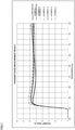
- FIG. 1 is a graph showing spectral transmittance distributions in a visible region (wavelength: 400 nm to 700 nm) and a neighboring region, in Examples 1 to 5 and Comparative examples 1 and 2.
- the spectral transmittance distributions were measured by a spectrophotometer (U-4100 manufactured by Hitachi High-Technologies Corporation).
- the transmittance in the visible region was within a band-shaped region of 27.5 ⁇ 4%, and visible light was uniformly absorbed at about an absorption rate of 27.5%, thus obtaining such a spectacle ND filter that a color recognized during wearing had almost no difference from that recognized by naked eyes while exhibiting a gray outer appearance.
- the absorption rate in the uniform absorption can be variously changed mainly by increasing/decreasing the total film thickness (the sum of film thicknesses) of the NiO x layers.
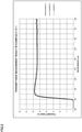
- FIG. 2 is a graph showing spectral transmittance distributions in the visible region and the neighboring region, in Examples 5 to 7.
- Example 5 The spectral transmittance distribution in Example 5 (thiourethane base with a refractive index of 1.60) is the same as that shown in FIG. 1 .
- Example 6 thiourethane base with a refractive index of 1.6
- Example 7 episulfide base with a refractive index of 1.70
- uniform absorption rates of about 27.5% were exhibited in the visible region, as in Example 5.
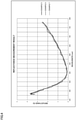
- FIG. 3 is a graph showing spectral reflectance distributions (one surface) in the visible region and the neighboring region, on the concave surface (ND film formed surface) side in Examples 1 to 5 and Comparative examples 1 and 2.
- the spectral reflectance distributions were measured by a reflectometer (USPM-RU manufactured by Olympus Corporation).
- each light absorbing film functions also as an antireflection film.
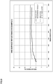
- FIG. 4 is a graph similar to FIG. 3 , for the concave surface (ND film formed surface) side in Examples 5 to 7.
- each light absorbing film functions also as an antireflection film.
- FIG. 5 is a graph showing a similarly measured spectral reflectance distribution (one surface, common) in the visible region on the convex surface side in Examples 1 to 5 and Comparative examples 1 and 2.
- the reflectance was approximately not greater than 4% in the visible region. Further, in a region not less than 420 nm and not greater than 700 nm corresponding to the major part of the visible region, the reflectance was not greater than 2%. Thus, reflection of the visible light was sufficiently prevented on the convex surface side.
- Tables 6 and 7 below show results of various tests for durability, i.e., a constant temperature and humidity test, a constant temperature and humidity test after lens shape processing, and a weather-resistance and adhesion test for the concave surface, in Examples 1 to 7 and Comparative examples 1 and 2.
- a constant temperature and humidity tester (LHU-113 manufactured by ESPEC CORP.) was used, and each ND filter was put in the tester having the environment of 60°C and 90%. After elapse of one day, three days, and seven days from the start of the putting, the ND filter was temporarily taken out, and whether or not abnormality of an outer appearance such as expansion, color change, or crack occurred was observed.
- lens shape processing was performed through cutting in a concentric shape having a diameter of 50 mm with a center part held, and thereafter the same procedure as in the above constant temperature and humidity test was performed (excluding observation after elapse of seven days).
- each concave surface was cut by a cutter so as to form 100 cells thereon in total, and a cellophane tape was adhered over the entirety of the cells and then vigorously peeled. This was repeated five times in total, and the number of cells where peeling did not occur therein was confirmed after completion of the total five-time peeling (initial). Further, the ND filter was put into a sunshine weather meter (S80B manufactured by Suga Test Instruments Co., Ltd.), and was taken out when the putting time reached 60 hours (h). Then, the above cell formation, five-time cellophane tape peeling, and confirmation of the number of cells, were performed.
- the light absorbing film in Comparative example 1 had the Al 2 O 3 layer in the first layer (initial layer) from the base, and therefore it is considered that the Al 2 O 3 layer could not follow swelling of the thiourethane resin base which absorbed a relatively large amount of moisture, thus causing optical strain.
- the initial layer was the ZrO 2 layer, and therefore it is inferred that the ZrO 2 layer followed swelling of the thiourethane base and thus occurrence of optical strain was prevented.
- Comparative example 1 a linear-shaped color change occurred at a lens center portion. Such color change was not confirmed immediately after the lens shape processing. As a cause of the color change, it is considered that slight crack occurred at the lens center portion which was the lens held portion in the lens shape processing, and through humidification, moisture concentrated on the crack, so that the NiO x layer was locally altered, resulting in abnormality of the transmittance.
- Al 2 O 3 exhibits a smaller deformation amount with respect to an external force, as compared to ZrO 2 and SiO 2 .
- the thiourethane resin is more readily deformed by an external force than the episulfide resin. Therefore, in Comparative example 1, it is considered that the lens surface was slightly bent due to holding in the lens shape processing, and the bending amount was larger in the thiourethane base and therefore the bending could not be followed by the Al 2 O 3 layer, resulting in crack.
- Example 7 the Al 2 O 3 layer was not used, and the SiO 2 +Al 2 O 3 layer and the ZrO 2 layer were used. Therefore, it is inferred that, in spite of the thiourethane base (in Example 7, episulfide base), the SiO 2 +Al 2 O 3 layer and the ZrO 2 layer followed bending of the lens surface in the lens shape processing, and thus crack did not occur even under exposure to the constant temperature and humidity environment after the lens shape processing.
- Examples 1 to 7 and Comparative example 1 in the weather-resistance and adhesion test, the number of cells where peeling occurred was five or less even when 240 hours elapsed, and thus favorable weather resistance was exhibited. In particular, in Examples 5 to 7 and Comparative example 1, peeling did not occur at any cell (no peeling at 100 cells) even when 240 hours elapsed, and thus favorable weather resistance was exhibited.
- FIG. 6 is a graph showing spectral reflectance distributions (one surface) in the visible region and the neighboring region, for a part where peeling occurred (peeled part) after the weather-resistance and adhesion test in Comparative example 2, and simulation in a case where the layers up to the third layer from the base side remained in the light absorbing film while the fourth and subsequent layers were lost.
- Example 1 had such a structure that the SiO 2 +Al 2 O 3 layer (film thickness: 60 nm) at the fourth layer in Comparative example 2 was replaced with the sandwich structure portion (film thicknesses: 30, 10, 30 nm) in which the ZrO 2 layer was sandwiched between the SiO 2 +Al 2 O 3 layers.
- the sandwich structure portion film thicknesses: 30, 10, 30 nm in which the ZrO 2 layer was sandwiched between the SiO 2 +Al 2 O 3 layers.
- stress in the air-side layer adjacent to the NiO x layer at the third layer where peeling could occur in the weather-resistance and adhesion test was relaxed, and thus favorable weather resistance and adhesion were obtained in Example 1.
- the first and second NiO x layers from the base side were each adjacent to not the ZrO 2 layer but the SiO 2 +Al 2 O 3 layer, and thereby were protected from moisture.
- Example 2 had such a structure that the SiO 2 +Al 2 O 3 layer (film thickness: 50 nm) adjacent, on the air side, to the second NiO x layer (the seventh layer) from the base side in Example 1 was replaced with the sandwich structure portion (film thicknesses: 25, 10, 25 nm).
- Example 2 exhibited a result equivalent to that in Example 1, and therefore it can be said that, even though the sandwich structure portion was added to the second NiO x layer from the base side, weather resistance and adhesion in Example 2 did not differ from Example 1 and thus were not improved very much.
- Example 3 had such a structure that the film thickness of the ZrO 2 layer of the sandwich structure portion in Example 1 was increased (from 10 nm to 15 nm).
- the film thickness of the ZrO 2 layer reached the half (50%) of the thickness of one SiO 2 +Al 2 O 3 layer (film thickness: 30 nm) and reached 1/4 (25%) of the total film thickness of the SiO 2 +Al 2 O 3 layers of the sandwich structure portion.
- Example 3 exhibited an improved result in the weather-resistance and adhesion test, as compared to Example 1. It is considered that such improvement was due to increase in the stress relaxing effect by the ZrO 2 layer.
- Example 4 had such a structure that the film thickness of each SiO 2 +Al 2 O 3 layer of the sandwich structure portion in Example 3 was decreased (from 30 nm to 25 nm). By this decrease, as compared to Example 3, the ratio of the film thickness of the ZrO 2 layer to the film thickness of one SiO 2 +Al 2 O 3 layer in the sandwich structure portion was increased to 60%, and the ratio thereof to the total film thickness of the SiO 2 +Al 2 O 3 layers was increased to 30%. Thus, the stress relaxing effect by the ZrO 2 layer was further increased and Example 4 exhibited an improved result in the weather-resistance and adhesion test as compared to Example 3.
- Example 5 had such a structure that, in the sandwich structure portion in Example 4, the film thickness of the SiO 2 +Al 2 O 3 layer on the base side was decreased (from 25 nm to 20 nm) and the film thickness of the SiO 2 +Al 2 O 3 layer on the air side was increased (from 25 nm to 30 nm) by the amount corresponding to the decrease, so that the film thickness on the base side was made smaller than the film thickness on the air side.
- stress directly acting on the NiO x layer was relaxed, thus exhibiting an extremely excellent result that peeling did not occur (100 cells remained) in the weather-resistance and adhesion test during 240 hours.
- Example 6 had such a structure that the same light absorbing film as in Example 5 was formed on the thiourethane base having a refractive index of 1.67. In Example 6, optical strain did not occur in the constant temperature and humidity test on the seventh day, for example, and thus durability equivalent to or higher than that in Example 5 was obtained.
- Example 7 had such a structure that the same light absorbing film as in Example 5 was formed on the episulfide base, and exhibited an extremely excellent durability equivalent to that in Example 6.
Landscapes
- Physics & Mathematics (AREA)
- Chemical & Material Sciences (AREA)
- General Physics & Mathematics (AREA)
- Optics & Photonics (AREA)
- Ophthalmology & Optometry (AREA)
- Health & Medical Sciences (AREA)
- Chemical Kinetics & Catalysis (AREA)
- Engineering & Computer Science (AREA)
- Materials Engineering (AREA)
- Mechanical Engineering (AREA)
- Metallurgy (AREA)
- Organic Chemistry (AREA)
- Inorganic Chemistry (AREA)
- General Health & Medical Sciences (AREA)
- Surface Treatment Of Optical Elements (AREA)
- Eyeglasses (AREA)
- Optical Elements Other Than Lenses (AREA)
- Optical Filters (AREA)
- Physical Vapour Deposition (AREA)
Applications Claiming Priority (2)
| Application Number | Priority Date | Filing Date | Title |
|---|---|---|---|
| JP2019108919A JP7385894B2 (ja) | 2019-06-11 | 2019-06-11 | プラスチック基材ndフィルタ及び眼鏡用プラスチック基材ndフィルタ |
| PCT/JP2020/022402 WO2020250837A1 (fr) | 2019-06-11 | 2020-06-05 | Filtre nd à substrat en plastique et filtre nd à substrat en plastique destiné à être utilisé dans des lunettes |
Publications (2)
| Publication Number | Publication Date |
|---|---|
| EP3968083A1 true EP3968083A1 (fr) | 2022-03-16 |
| EP3968083A4 EP3968083A4 (fr) | 2023-02-22 |
Family
ID=73743693
Family Applications (1)
| Application Number | Title | Priority Date | Filing Date |
|---|---|---|---|
| EP20822280.2A Pending EP3968083A4 (fr) | 2019-06-11 | 2020-06-05 | Filtre nd à substrat en plastique et filtre nd à substrat en plastique destiné à être utilisé dans des lunettes |
Country Status (6)
| Country | Link |
|---|---|
| US (1) | US20220091315A1 (fr) |
| EP (1) | EP3968083A4 (fr) |
| JP (1) | JP7385894B2 (fr) |
| KR (1) | KR20220016866A (fr) |
| CN (1) | CN113994242A (fr) |
| WO (1) | WO2020250837A1 (fr) |
Family Cites Families (7)
| Publication number | Priority date | Publication date | Assignee | Title |
|---|---|---|---|---|
| JP2001074911A (ja) * | 1999-09-08 | 2001-03-23 | Nippon Electric Glass Co Ltd | 導電性反射防止膜及びそれが被覆形成された陰極線管用ガラスパネル |
| TW593187B (en) * | 1999-10-25 | 2004-06-21 | Nippon Sheet Glass Co Ltd | Method for preparing article covered with light absorption pattern film and article covered with light absorption pattern film |
| JP4747438B2 (ja) * | 2001-05-15 | 2011-08-17 | 凸版印刷株式会社 | 導電性反射防止フィルム |
| WO2011059430A1 (fr) * | 2009-11-11 | 2011-05-19 | Essilor International | Composition de traitement de surface, son procédé de production, et article à surface traitée |
| JP2012073542A (ja) * | 2010-09-29 | 2012-04-12 | Fujifilm Corp | 反射防止膜及びその製造方法、光学部材、並びにプラスチックレンズ |
| EP3407100B1 (fr) * | 2016-02-23 | 2023-12-20 | Tokai Optical Co., Ltd. | Filtre à densité neutre (nd) à matériau de base en plastique, et filtre nd à matériau de base en plastique pour lunettes |
| JP6944623B2 (ja) * | 2016-08-29 | 2021-10-06 | 東海光学株式会社 | Ndフィルタの製造方法 |
-
2019
- 2019-06-11 JP JP2019108919A patent/JP7385894B2/ja active Active
-
2020
- 2020-06-05 CN CN202080042001.6A patent/CN113994242A/zh active Pending
- 2020-06-05 WO PCT/JP2020/022402 patent/WO2020250837A1/fr unknown
- 2020-06-05 EP EP20822280.2A patent/EP3968083A4/fr active Pending
- 2020-06-05 KR KR1020217040683A patent/KR20220016866A/ko active Search and Examination
-
2021
- 2021-12-02 US US17/457,317 patent/US20220091315A1/en active Pending
Also Published As
| Publication number | Publication date |
|---|---|
| US20220091315A1 (en) | 2022-03-24 |
| EP3968083A4 (fr) | 2023-02-22 |
| JP2020201412A (ja) | 2020-12-17 |
| JP7385894B2 (ja) | 2023-11-24 |
| WO2020250837A1 (fr) | 2020-12-17 |
| KR20220016866A (ko) | 2022-02-10 |
| CN113994242A (zh) | 2022-01-28 |
Similar Documents
| Publication | Publication Date | Title |
|---|---|---|
| EP3407100B1 (fr) | Filtre à densité neutre (nd) à matériau de base en plastique, et filtre nd à matériau de base en plastique pour lunettes | |
| JP6740118B2 (ja) | 紫外領域及び可視領域の両方において低い反射性を持つ反射防止膜を有する光学部品 | |
| CN109844573B (zh) | 在近红外区和蓝光区具有高反射的光学制品 | |
| US6863397B2 (en) | Optical element and eyeglass lens | |
| EP3088921B1 (fr) | Produit optique, verres de lunettes et lunettes | |
| EP2589992B1 (fr) | Produit optique et lentille de lunettes en matière plastique | |
| EP2804026B1 (fr) | Produit optique et son procédé de fabrication | |
| EP3489727B1 (fr) | Produit optique, verre de lunettes en plastique et lunettes | |
| EP3208653B1 (fr) | Verre de lunettes et lunettes | |
| JP2019515352A (ja) | 近赤外領域(nir)において高反射率を有する反射防止膜を含む光学物品 | |
| US11709292B2 (en) | Optical plastic product, and plastic spectacle lens and spectacles | |
| EP3968083A1 (fr) | Filtre nd à substrat en plastique et filtre nd à substrat en plastique destiné à être utilisé dans des lunettes | |
| KR20180078328A (ko) | 안경 렌즈 및 안경 | |
| EP3992672A1 (fr) | Élément optique, système optique et appareil optique | |
| BR112021009285A2 (pt) | lente óptica tendo um revestimento de espelho e um sistema multicamada para melhoramento da resistência à abrasão | |
| WO2022244768A1 (fr) | Élément électrochromique et verre de lunettes | |
| EP4109141A1 (fr) | Lentille optique comportant un revêtement interférentiel absorbant la lumière |
Legal Events
| Date | Code | Title | Description |
|---|---|---|---|
| STAA | Information on the status of an ep patent application or granted ep patent |
Free format text: STATUS: THE INTERNATIONAL PUBLICATION HAS BEEN MADE |
|
| PUAI | Public reference made under article 153(3) epc to a published international application that has entered the european phase |
Free format text: ORIGINAL CODE: 0009012 |
|
| STAA | Information on the status of an ep patent application or granted ep patent |
Free format text: STATUS: REQUEST FOR EXAMINATION WAS MADE |
|
| 17P | Request for examination filed |
Effective date: 20211210 |
|
| AK | Designated contracting states |
Kind code of ref document: A1 Designated state(s): AL AT BE BG CH CY CZ DE DK EE ES FI FR GB GR HR HU IE IS IT LI LT LU LV MC MK MT NL NO PL PT RO RS SE SI SK SM TR |
|
| DAV | Request for validation of the european patent (deleted) | ||
| DAX | Request for extension of the european patent (deleted) | ||
| A4 | Supplementary search report drawn up and despatched |
Effective date: 20230125 |
|
| RIC1 | Information provided on ipc code assigned before grant |
Ipc: G02B 5/22 20060101ALI20230119BHEP Ipc: G02B 5/20 20060101ALI20230119BHEP Ipc: C23C 14/20 20060101ALI20230119BHEP Ipc: C23C 14/08 20060101ALI20230119BHEP Ipc: G02B 5/00 20060101ALI20230119BHEP Ipc: G02B 1/115 20150101ALI20230119BHEP Ipc: G02C 7/10 20060101AFI20230119BHEP |
|
| GRAP | Despatch of communication of intention to grant a patent |
Free format text: ORIGINAL CODE: EPIDOSNIGR1 |
|
| STAA | Information on the status of an ep patent application or granted ep patent |
Free format text: STATUS: GRANT OF PATENT IS INTENDED |
|
| INTG | Intention to grant announced |
Effective date: 20240311 |