EP3967990B1 - Method and apparatus for measuring fuel tank, and server - Google Patents
Method and apparatus for measuring fuel tank, and server Download PDFInfo
- Publication number
- EP3967990B1 EP3967990B1 EP20831909.5A EP20831909A EP3967990B1 EP 3967990 B1 EP3967990 B1 EP 3967990B1 EP 20831909 A EP20831909 A EP 20831909A EP 3967990 B1 EP3967990 B1 EP 3967990B1
- Authority
- EP
- European Patent Office
- Prior art keywords
- liquid level
- volume
- level pressure
- fuel tank
- fuel quantity
- Prior art date
- Legal status (The legal status is an assumption and is not a legal conclusion. Google has not performed a legal analysis and makes no representation as to the accuracy of the status listed.)
- Active
Links
Images


Classifications
-
- G—PHYSICS
- G01—MEASURING; TESTING
- G01F—MEASURING VOLUME, VOLUME FLOW, MASS FLOW OR LIQUID LEVEL; METERING BY VOLUME
- G01F25/00—Testing or calibration of apparatus for measuring volume, volume flow or liquid level or for metering by volume
- G01F25/0084—Testing or calibration of apparatus for measuring volume, volume flow or liquid level or for metering by volume for measuring volume
-
- G—PHYSICS
- G01—MEASURING; TESTING
- G01F—MEASURING VOLUME, VOLUME FLOW, MASS FLOW OR LIQUID LEVEL; METERING BY VOLUME
- G01F17/00—Methods or apparatus for determining the capacity of containers or cavities, or the volume of solid bodies
-
- G—PHYSICS
- G01—MEASURING; TESTING
- G01F—MEASURING VOLUME, VOLUME FLOW, MASS FLOW OR LIQUID LEVEL; METERING BY VOLUME
- G01F22/00—Methods or apparatus for measuring volume of fluids or fluent solid material, not otherwise provided for
- G01F22/02—Methods or apparatus for measuring volume of fluids or fluent solid material, not otherwise provided for involving measurement of pressure
-
- B—PERFORMING OPERATIONS; TRANSPORTING
- B60—VEHICLES IN GENERAL
- B60K—ARRANGEMENT OR MOUNTING OF PROPULSION UNITS OR OF TRANSMISSIONS IN VEHICLES; ARRANGEMENT OR MOUNTING OF PLURAL DIVERSE PRIME-MOVERS IN VEHICLES; AUXILIARY DRIVES FOR VEHICLES; INSTRUMENTATION OR DASHBOARDS FOR VEHICLES; ARRANGEMENTS IN CONNECTION WITH COOLING, AIR INTAKE, GAS EXHAUST OR FUEL SUPPLY OF PROPULSION UNITS IN VEHICLES
- B60K15/00—Arrangement in connection with fuel supply of combustion engines or other fuel consuming energy converters, e.g. fuel cells; Mounting or construction of fuel tanks
- B60K15/03—Fuel tanks
- B60K2015/03328—Arrangements or special measures related to fuel tanks or fuel handling
- B60K2015/03361—Arrangements or special measures related to fuel tanks or fuel handling for checking the quality or quantity of fuel during filling of fuel tank
-
- B—PERFORMING OPERATIONS; TRANSPORTING
- B60—VEHICLES IN GENERAL
- B60Y—INDEXING SCHEME RELATING TO ASPECTS CROSS-CUTTING VEHICLE TECHNOLOGY
- B60Y2400/00—Special features of vehicle units
- B60Y2400/30—Sensors
- B60Y2400/306—Pressure sensors
-
- G—PHYSICS
- G01—MEASURING; TESTING
- G01F—MEASURING VOLUME, VOLUME FLOW, MASS FLOW OR LIQUID LEVEL; METERING BY VOLUME
- G01F23/00—Indicating or measuring liquid level or level of fluent solid material, e.g. indicating in terms of volume or indicating by means of an alarm
- G01F23/14—Indicating or measuring liquid level or level of fluent solid material, e.g. indicating in terms of volume or indicating by means of an alarm by measurement of pressure
- G01F23/18—Indicating, recording or alarm devices actuated electrically
Definitions
- This application relates to the field of fuel tank calibration, and specifically, to a method for measuring the volume of a fuel tank, a device for measuring the volume of a fuel tank and a server.
- Detection on a fuel tank includes fuel level detection, fuel level status detection, and detection whether refueling is required, and so on.
- CN 104 634 409 B discloses a device for calibrating a tank volume and a corresponding method.
- the device can automatically calibrate a flow meter in order to improve its accuracy.
- KR 2006 0047387 A discloses a measuring system using ultrasonic waves for accurately measuring the distance from the top of a storage container to the surface of the liquid through ultrasonic waves, and then calculating the temperature, pressure, and distance to accurately measure the volume of the liquid contained in the container and the weight of the contents.
- RU 2 047 108 C1 discloses a device for measuring the level and the density of a liquid in a container using an ultrasonic piezoelectric transducer (PEP), and the emission of ultrasonic pulses is carried out perpendicular to the liquid level from the bottom point of the bottom of the tank.
- the piezoelectric transducer is installed vertically at the bottom point of the tank bottom and is additionally equipped with a density measurement and calculation unit.
- This application is mainly intended to provide a method and device for measuring the volume of a fuel tank, and a server, to resolve problems of poor fuel tank metering management, because the volume of different types of fuel tanks cannot be intelligently estimated.
- a method for measuring the volume of a fuel tank is provided.
- the problem, on which the invention is based, is solved by a method with the features of claim 1.
- the method for measuring the volume of a fuel tank according to this application includes: receiving a fuel quantity change parameter calibrated by a user at a smart terminal; receiving a measured liquid level pressure value collected from a fueling terminal through a sensor according to a preset frequency; and inputting the fuel quantity change parameter and the measured liquid level pressure value into a preset volume calibration model and estimating the volume of the fuel tank.
- the volume calibration model at least includes a maximum liquid level pressure value, when the fuel tank is full, and a minimum liquid level pressure value, when the fuel tank is empty, wherein these pressure values are extracted from the received pressure.
- the operation of receiving the fuel quantity change parameter calibrated by the user at the smart terminal includes: monitoring whether the smart terminal has a user calibration operation; if yes, generating the fuel quantity change parameter according to the user calibration operation; and receiving the fuel quantity change parameter.
- the operation of receiving the measured liquid level pressure value collected from the fueling terminal through the sensor according to the preset frequency includes: receiving a parameter set of liquid level pressure collected from the fueling terminal through the sensor according to the preset frequency; and recording and storing the parameter set of the liquid level pressure.
- the operation of inputting the fuel quantity change parameter and the measured liquid level pressure value into a preset volume calibration model and estimating the volume of the fuel tank includes: extracting a minimum liquid level pressure and a maximum liquid level pressure in the measured liquid level pressure value; determining a correspondence between hydraulic pressure and a volume percentage according to variation of the liquid level pressure with time; estimating a capacity change percentage according to the minimum liquid level pressure, the maximum liquid level pressure and the correspondence between the hydraulic pressure and the volume percentage; and inversely deducing the volume of the fuel tank according to the capacity quantity change percentage and the fuel quantity change parameter.
- the operation after inputting the fuel quantity change parameter and the measured liquid level pressure value into the preset volume calibration model and estimating the volume of the fuel tank further includes: extracting the maximum liquid level pressure in the measured liquid level pressure value; determining the correspondence between the hydraulic pressure and the volume percentage according to the variation of the liquid level pressure with time; estimating a current capacity percentage according to the maximum liquid level pressure and the correspondence between the hydraulic pressure and the volume percentage; and calculating a current fuel quantity according to the volume of the fuel tank and the current capacity percentage.
- the operation before receiving the fuel quantity change parameter calibrated by the user at the smart terminal further includes: detecting a refueling event by using a fuel tank cap detecting device on the fueling terminal; and if the refueling event is detected, receiving the fuel quantity change parameter calibrated by the user at the smart terminal.
- a device for measuring the volume of a fuel tank is provided.
- the device for measuring the volume of the fuel tank includes a first receiving module, a second receiving module, and a volume estimating module.
- the first receiving module is configured to receive a fuel quantity change parameter calibrated by a user at a smart terminal.
- the second receiving module is configured to receive a measured liquid level pressure value collected from a fueling terminal through a sensor according to a preset frequency, wherein the second receiving module is configured to extract a minimum liquid level pressure and a maximal liquid level pressure from the received pressure.
- the volume estimating module is configured to input the fuel quantity change parameter and the measured liquid level pressure value into a preset volume calibration model and to estimate the volume of the fuel tank.
- the volume calibration model at least includes a liquid level pressure value, when the fuel tank is full, and a liquid level pressure value, when the fuel tank is empty.
- the volume estimating module is configured to extract a minimum liquid level pressure and a maximum liquid level pressure in the measured liquid level pressure value, determine a correspondence between hydraulic pressure and a volume percentage according to variation of the liquid level pressure with time, estimate a capacity change percentage according to the minimum liquid level pressure, the maximum liquid level pressure and the correspondence between the hydraulic pressure and the volume percentage, and inversely deduce the volume of the fuel tank according to a fuel quantity change percentage and the fuel quantity change parameter.
- the device further includes a monitoring module.
- the monitoring module is configured to extract the maximum liquid level pressure in the measured liquid level pressure value, determine the correspondence between the hydraulic pressure and the volume percentage according to the variation of the liquid level pressure with time, estimate a current capacity percentage according to the maximum liquid level pressure and the correspondence between the hydraulic pressure and the volume percentage, and calculate a current fuel quantity according to the volume of the fuel tank and the current capacity percentage.
- a server is provided.
- the server according to this application is configured to perform the foregoing measurement method.
- the fuel quantity change parameter calibrated by the user at the smart terminal is received.
- the measured liquid level pressure value collected from the fueling terminal through the sensor according to the preset frequency is received.
- the fuel quantity change parameter and the measured liquid level pressure value are input into the preset volume calibration model, and the volume of the fuel tank is estimated.
- the volume calibration model at least includes a full fueling liquid level pressure value and an air liquid level pressure value.
- orientation or position relationships indicated by terms “upper”, “lower”, “left”, “right”, “front”, “back”, “top”, “bottom”, “inside”, “outside” “in”, “vertical”, “horizontal”, “transverse”, “longitudinal” and the like are orientation or position relationships shown in the drawings. These terms are mainly used to better describe this application and its embodiments, rather than limit that the indicated devices, components and constituting parts must be in specific orientations or structured and operated in the specific orientations.
- connection may be fixed connection, detachable connection or integral construction.
- connect may be mechanical connection, or electrical connection.
- connect may be direct connection, or indirect connection through a medium, or communication in two devices, components or constituting parts.
- the method in an embodiment of this application includes the following S100 to S104.
- a fuel quantity change parameter calibrated by a user at a smart terminal is received.
- the operation of receiving the fuel quantity change parameter calibrated by the user at the smart terminal includes the following steps.
- the fuel quantity change parameter is generated according to the user calibration operation.
- the smart terminal may be portable devices, such as a mobile phone and a tablet computer, or may be a personal computer (pc).
- the mobile phone is preferred.
- Application processing software is installed on the mobile phone, and by means of the software, the user may calibrate the fuel quantity change parameter. Specifically, the user opens the software to enter an interactive interface, and inputs fuel quantity, namely the fuel quantity change parameter, of this fueling in the interactive interface through calibration operation. After the fuel quantity change parameter is acquired, the fuel quantity change parameter is sent to the server. In this way, parameter guarantee may be provided for the volume estimation of the server.
- the smart terminal communicates with the server in wireless transmission modes, such as GPRS, 3G, 4G, and WiFi.
- wireless transmission modes such as GPRS, 3G, 4G, and WiFi.
- the measurement method is only applicable for volume measurement of regular fuel tanks, such as a cuboid fuel tank and a cube fuel tank.
- the operation before receiving the fuel quantity change parameter calibrated by the user at the smart terminal further includes the following steps.
- a refueling event is detected by using a fuel tank cap detecting device on the fueling terminal.
- the receiving of the fuel quantity change parameter can be triggered.
- a prompt message is sent to the smart terminal with a binding relationship, to prompt the user to start refueling.
- the user may click the prompt message, so that the application processing software can be automatically opened, then corresponding calibration operation is performed to upload the fuel quantity change parameter to the server.
- a link of a stopping reason for no refueling event is output at the smart terminal.
- the user may click the link to directly open the software, so as to enter a software interface to check the stopping reason. In this way, the user may continue to operate to restart a program after checking and eliminating the reason on site.
- the prompt message may be actively sent. Prompt personnel complete the uploading of the fuel quantity change parameter through the operation of the application processing software. When there is no refueling events, the procedure is stopped, and the uploading of the fuel quantity change parameter is completed only after the user opens the software to operate.
- a measurement parameter collected from a fueling terminal through a sensor according to a preset frequency is received.
- the operation of receiving the measurement parameter collected from the fueling terminal through the sensor according to the preset frequency includes the following steps.
- the parameter set of liquid level pressure is recorded and stored.
- the fuel quantity change parameter is one of parameters of the estimated volume of the fuel tank, so that it requires a plurality of measurement parameters during refueling to realize the estimation of the volume of the fuel tank.
- the sensor can periodically collect the measurement parameters. That is to say, the liquid level pressure is detected and recorded every a period of time, so as to acquire one parameter set of the liquid level pressure.
- the liquid level pressure in the parameter set of the liquid level pressure is stored one by one. After refueling is finished, the liquid level pressure is uniformly uploaded to the server, to estimate the volume of the fuel tank.
- the fuel quantity change parameter and the measurement parameter are input into a preset volume calibration model and the volume of the fuel tank is estimated.
- the volume calibration model at least comprises a full fueling liquid level pressure value and an air liquid level pressure value.
- the air liquid level pressure value is constant to any fuel tanks. Thus, it only needs to be preset in a volume calibration model as a default parameter at factory.
- the air liquid level pressure value is an essential parameter during volume estimation. In this embodiment, preferably, a plurality of calibration may be performed, so that the accuracy of the estimated volume can be enhanced.
- the full fueling liquid level pressure value may vary with the height of the fuel tank. Therefore, when refueling is performed at the first time, personnel needs to be reminded that it is in a fueling state, and a measured maximum liquid level pressure value acts as the full fueling liquid level pressure value.
- the full fueling liquid level pressure value is an essential parameter during volume estimation.
- the volume of the fuel tank is estimated.
- the operation of inputting the fuel quantity change parameter and the measurement parameter into the preset volume calibration model and estimating the volume of the fuel tank includes the following steps.
- a correspondence between hydraulic pressure and a volume percentage is determined according to variation of the liquid level pressure with time.
- a capacity change percentage is estimated according to the minimum liquid level pressure, the maximum liquid level pressure and the correspondence between the hydraulic pressure and the volume percentage.
- the volume of the fuel tank is inversely deduced according to a fuel quantity change percentage and the fuel quantity change parameter.
- the capacity change percentage is related to the minimum liquid level pressure and the maximum liquid level pressure, and is unrelated to a refueling process.
- the minimum liquid level pressure the liquid level pressure before refueling
- the maximum liquid level pressure the liquid level pressure after refueling
- whether a refueling rate is constant is not limited.
- a constant refueling rate may be adopted, or a non-constant refueling rate may also be adopted.
- ⁇ v generated in ⁇ t is the same. If a collection rate of hardware is constant, the ⁇ t between two adjacent hydraulic pressure data points is the same, and the corresponding ⁇ v is the same.
- Pi ⁇ 1 ...n ⁇ is set as a hydraulic pressure value collected at a fixed frequency at a refueling phase.
- the hydraulic pressure value in air is known as P0.
- the bottom shape of the fuel tank is regular.
- Pn is a collected maximum hydraulic pressure value point.
- P1 is a minimum hydraulic pressure value point collected at one time.
- Polynomial fitting (Pi, i-1) is performed by using Pi ⁇ 1...m ⁇ (m ⁇ n) to acquire a slope k and an offset b.
- Index0 P0 * k + b corresponding to P0 is calculated by using the k, the b and the hydraulic pressure value P0 in air.
- Pct 1 0 ⁇ Index 0 / n ⁇ 1 ⁇ Index 0
- the minimum and maximum liquid level pressure in the measurement parameter are extracted. Referring to the correspondence between the hydraulic pressure values and the percentages, the percentage of capacity change can be determined, and then the volume of the fuel tank can be inversely deduced. Therefore, accurate and intelligent calculation of the volume of the fuel tank is realized, and further fuel tank metering management is achieved.
- the operation after inputting the fuel quantity change parameter and the measurement parameter into the preset volume calibration model and estimating the volume of the fuel tank further includes the following steps.
- the maximum liquid level pressure in the measurement parameter is extracted.
- a correspondence between hydraulic pressure and a volume percentage is determined according to variation of the liquid level pressure with time.
- a current capacity percentage is estimated according to the maximum liquid level pressure and the correspondence between the hydraulic pressure and the volume percentage.
- a current fuel quantity is calculated according to the volume of the fuel tank and the current capacity percentage.
- Index0 P0 * k + b, (Pi, Pcti) may be determined to achieve one-to-one correspondence, so as to form a complete correspondence between the hydraulic pressure values and the percentages.
- the current capacity percentage can be determined, and the current fuel quantity may be calculated by multiplying the percentage by the volume of the fuel tank.
- the calculation of the current fuel quantity may achieve further fuel tank metering management of fuel theft and fuel leakage.
- a fuel pressure-time curve of an excavator in one day is collected, as shown in Fig. 9 , which shows fuel pressure data collected by the hardware terminal and the fuel pressure data after piecewise fitting.
- the refueling phase data in the middle is extracted to perform calibration calculation.
- An acquired hydraulic pressure and fuel level percentage is shown in Fig. 10 .
- a horizontal ordinate is the hydraulic pressure value, and a vertical coordinate is the percentage.
- the fuel quantity change parameter calibrated by the user at the smart terminal is received.
- the measurement parameter collected from the fueling terminal through the sensor according to the preset frequency is received.
- the fuel quantity change parameter and the measurement parameter are input into the preset volume calibration model, and the volume of the fuel tank is estimated.
- the volume calibration model at least includes a full fueling liquid level pressure value and an air liquid level pressure value.
- the device includes a first receiving module 10.
- the first receiving module 10 is configured to receive a fuel quantity change parameter calibrated by a user at a smart terminal.
- the operation of receiving the fuel quantity change parameter calibrated by the user at the smart terminal includes the following operations.
- the fuel quantity change parameter is generated according to the user calibration operation.
- the fuel quantity change parameter is received.
- the smart terminal may be portable devices, such as a mobile phone and a tablet computer, or may be a personal computer (pc).
- the mobile phone is preferred.
- Application processing software is installed on the mobile phone, and by means of the software, the user may calibrate the fuel quantity change parameter. Specifically, the user opens the software to enter an interactive interface, and inputs fuel quantity, namely the fuel quantity change parameter, of this fueling in the interactive interface through calibration operation. After the fuel quantity change parameter is acquired, the fuel quantity change parameter is sent to the server. In this way, parameter guarantee may be provided for the volume estimation of the server.
- the smart terminal communicates with the server in wireless transmission modes, such as GPRS, 3G, 4G, and WiFi.
- wireless transmission modes such as GPRS, 3G, 4G, and WiFi.
- the measurement method is only applicable for volume measurement of regular fuel tanks, such as a cuboid fuel tank and a cube fuel tank.
- the operation before receiving the fuel quantity change parameter calibrated by the user at the smart terminal further includes the following operations.
- a refueling event is detected by using a fuel tank cap detecting device on the fueling terminal.
- the fuel quantity change parameter calibrated by the user at the smart terminal is received.
- the receiving of the fuel quantity change parameter can be triggered.
- a prompt message is sent to the smart terminal with a binding relationship, to prompt the user to start refueling.
- the user may click the prompt message, so that the application processing software can be automatically opened, then corresponding calibration operation is performed to upload the fuel quantity change parameter to the server.
- a link of a stopping reason for no refueling event is output at the smart terminal.
- the user may click the link to directly open the software, so as to enter a software interface to check the stopping reason. In this way, the user may continue to operate to restart a program after checking and eliminating the reason on site.
- the prompt message may be actively sent. Prompt personnel complete the uploading of the fuel quantity change parameter through the operation of the application processing software. When there is no refueling events, the procedure is stopped, and the uploading of the fuel quantity change parameter is completed only after the user opens the software to operate.
- a second receiving module 20 is configured to receive the measurement parameter collected from the fueling terminal through the sensor according to the preset frequency.
- the operation of receiving the measurement parameter collected from the fueling terminal through the sensor according to the preset frequency includes the following operations.
- a parameter set of liquid level pressure collected from the fueling terminal through the sensor according to the preset frequency is received.
- the parameter set of the liquid level pressure is recorded and stored.
- the fuel quantity change parameter is one of parameters of the estimated volume of the fuel tank, so that it requires a plurality of measurement parameters during refueling to realize the estimation of the volume of the fuel tank.
- the sensor can periodically collect the measurement parameters. That is to say, the liquid level pressure is detected and recorded every a period of time, so as to acquire one parameter set of the liquid level pressure.
- the liquid level pressure in the parameter set of the liquid level pressure is stored one by one. After refueling is finished, the liquid level pressure is uniformly uploaded to the server, to estimate the volume of the fuel tank.
- a volume estimating module 30 is configured to input the fuel quantity change parameter and the measurement parameter into the preset volume calibration model, and estimate the volume of the fuel tank.
- the volume calibration model at least includes a full fueling liquid level pressure value and an air liquid level pressure value.
- the air liquid level pressure value is constant to any fuel tanks. Thus, it only needs to be preset in a volume calibration model as a default parameter at factory.
- the air liquid level pressure value is an essential parameter during volume estimation.
- the full fueling liquid level pressure value may vary with the height of the fuel tank. Therefore, when refueling is performed at the first time, personnel needs to be reminded that it is in a fueling state, and a measured maximum liquid level pressure value acts as the full fueling liquid level pressure value.
- the full fueling liquid level pressure value is an essential parameter during volume estimation.
- the volume of the fuel tank is estimated.
- the volume estimating module 30 is configured to perform the following operations.
- a minimum liquid level pressure and a maximum liquid level pressure in the measurement parameter are extracted.
- the correspondence between the hydraulic pressure and the volume percentage is determined according to the variation of the liquid level pressure with time.
- a capacity change percentage is estimated according to the minimum liquid level pressure, the maximum liquid level pressure and the correspondence between the hydraulic pressure and the volume percentage.
- the volume of the fuel tank is inversely deduced according to a fuel quantity change percentage and the fuel quantity change parameter.
- the capacity change percentage is related to the minimum liquid level pressure and the maximum liquid level pressure, and is unrelated to the refueling process.
- the minimum liquid level pressure the liquid level pressure before refueling
- the maximum liquid level pressure the liquid level pressure after refueling
- whether a refueling rate is constant is not limited.
- the constant refueling rate may be adopted, or the non-constant refueling rate may also be adopted.
- ⁇ v generated in ⁇ t is the same. If a collection rate of hardware is constant, the ⁇ t between two adjacent hydraulic pressure data points is the same, and the corresponding ⁇ v is the same.
- Pi ⁇ 1 ...n ⁇ is set as a hydraulic pressure value collected at a fixed frequency at a refueling phase.
- the hydraulic pressure value in air is known as P0.
- the bottom shape of the fuel tank is regular.
- Pn is a collected maximum hydraulic pressure value point.
- P1 is a minimum hydraulic pressure value point collected at one time.
- Polynomial fitting (Pi, i-1) is performed by using Pi ⁇ 1...m ⁇ (m ⁇ n) to acquire a slope k and an offset b.
- Subscript Index0 corresponding to P0 is calculated by using the k, the b and the hydraulic pressure value P0 in air.
- Pct 1 0 ⁇ Index 0 / n ⁇ 1 ⁇ Index 0
- the minimum and maximum liquid level pressure in the measurement parameter are extracted. Referring to the correspondence between the hydraulic pressure values and the percentages, the percentage of capacity change can be determined, and then the volume of the fuel tank can be inversely deduced. Therefore, accurate and intelligent calculation of the volume of the fuel tank is realized, and further fuel tank metering management is achieved.
- the device further includes a monitoring module 40.
- the monitoring module 40 is configured to perform the following operations.
- the maximum liquid level pressure in the measurement parameter is extracted.
- the correspondence between the hydraulic pressure and the volume percentage is determined according to the variation of the liquid level pressure with time.
- a current capacity percentage is estimated according to the maximum liquid level pressure and the correspondence between the hydraulic pressure and the volume percentage.
- a current fuel quantity is calculated according to the volume of the fuel tank and the current capacity percentage.
- Index0 P0 * k + b, (Pi, Pcti) may be determined to achieve one-to-one correspondence, so as to form a complete correspondence between the hydraulic pressure values and the percentages.
- the current capacity percentage can be determined, and the current fuel quantity may be calculated by multiplying the percentage by the volume of the fuel tank.
- the calculation of the current fuel quantity may achieve further fuel tank metering management of fuel theft and fuel leakage.
- the fuel quantity change parameter calibrated by the user at the smart terminal is received.
- the measurement parameter collected from the fueling terminal through the sensor according to the preset frequency is received.
- the fuel quantity change parameter and the measurement parameter are input into the preset volume calibration model, and the volume of the fuel tank is estimated.
- the volume calibration model at least includes a full fueling liquid level pressure value and an air liquid level pressure value.
- modules or steps of this application may be implemented by a general computing device, and may also be gathered together on a single computing device or distributed in network composed of multiple computing devices.
- the above mentioned modules or steps of this application may be implemented with program codes executable by the computing device, so that may be stored in a storage device for execution by the computing device, or can be fabricated into individual integrated circuit modules respectively, or multiple modules or steps thereof are fabricated into a single integrated circuit module for implementation. In this way, this application is not limited to any specific combination of hardware and software.
Landscapes
- Physics & Mathematics (AREA)
- Fluid Mechanics (AREA)
- General Physics & Mathematics (AREA)
- Measurement Of Levels Of Liquids Or Fluent Solid Materials (AREA)
Description
- This application relates to the field of fuel tank calibration, and specifically, to a method for measuring the volume of a fuel tank, a device for measuring the volume of a fuel tank and a server.
- Detection on a fuel tank includes fuel level detection, fuel level status detection, and detection whether refueling is required, and so on.
- Inventors have discovered that, if the volume of the fuel tank is inaccurate, metering management of different types of the fuel tanks may be influenced.
- In view of a problem in the related art of poor fuel tank metering management, because the volume of different types of fuel tanks cannot be intelligently estimated, no effective solutions have been proposed currently.
-
CN 104 634 409 B -
KR 2006 0047387 A -
RU 2 047 108 C1 - This application is mainly intended to provide a method and device for measuring the volume of a fuel tank, and a server, to resolve problems of poor fuel tank metering management, because the volume of different types of fuel tanks cannot be intelligently estimated.
- In order to realize the above purpose, according to one aspect of this application, a method for measuring the volume of a fuel tank is provided.
- The problem, on which the invention is based, is solved by a method with the features of claim 1. The method for measuring the volume of a fuel tank according to this application includes: receiving a fuel quantity change parameter calibrated by a user at a smart terminal; receiving a measured liquid level pressure value collected from a fueling terminal through a sensor according to a preset frequency; and inputting the fuel quantity change parameter and the measured liquid level pressure value into a preset volume calibration model and estimating the volume of the fuel tank. The volume calibration model at least includes a maximum liquid level pressure value, when the fuel tank is full, and a minimum liquid level pressure value, when the fuel tank is empty, wherein these pressure values are extracted from the received pressure.
- Further, the operation of receiving the fuel quantity change parameter calibrated by the user at the smart terminal includes: monitoring whether the smart terminal has a user calibration operation; if yes, generating the fuel quantity change parameter according to the user calibration operation; and receiving the fuel quantity change parameter.
- Further, the operation of receiving the measured liquid level pressure value collected from the fueling terminal through the sensor according to the preset frequency includes: receiving a parameter set of liquid level pressure collected from the fueling terminal through the sensor according to the preset frequency; and recording and storing the parameter set of the liquid level pressure.
- Further, the operation of inputting the fuel quantity change parameter and the measured liquid level pressure value into a preset volume calibration model and estimating the volume of the fuel tank includes: extracting a minimum liquid level pressure and a maximum liquid level pressure in the measured liquid level pressure value; determining a correspondence between hydraulic pressure and a volume percentage according to variation of the liquid level pressure with time; estimating a capacity change percentage according to the minimum liquid level pressure, the maximum liquid level pressure and the correspondence between the hydraulic pressure and the volume percentage; and inversely deducing the volume of the fuel tank according to the capacity quantity change percentage and the fuel quantity change parameter.
- Further, the operation after inputting the fuel quantity change parameter and the measured liquid level pressure value into the preset volume calibration model and estimating the volume of the fuel tank further includes: extracting the maximum liquid level pressure in the measured liquid level pressure value; determining the correspondence between the hydraulic pressure and the volume percentage according to the variation of the liquid level pressure with time; estimating a current capacity percentage according to the maximum liquid level pressure and the correspondence between the hydraulic pressure and the volume percentage; and calculating a current fuel quantity according to the volume of the fuel tank and the current capacity percentage.
- Further, the operation before receiving the fuel quantity change parameter calibrated by the user at the smart terminal further includes: detecting a refueling event by using a fuel tank cap detecting device on the fueling terminal; and if the refueling event is detected, receiving the fuel quantity change parameter calibrated by the user at the smart terminal.
- In order to realize the above purpose, according to another aspect of this application, a device for measuring the volume of a fuel tank is provided.
- The device for measuring the volume of the fuel tank according to this application includes a first receiving module, a second receiving module, and a volume estimating module. The first receiving module is configured to receive a fuel quantity change parameter calibrated by a user at a smart terminal. The second receiving module is configured to receive a measured liquid level pressure value collected from a fueling terminal through a sensor according to a preset frequency, wherein the second receiving module is configured to extract a minimum liquid level pressure and a maximal liquid level pressure from the received pressure. The volume estimating module is configured to input the fuel quantity change parameter and the measured liquid level pressure value into a preset volume calibration model and to estimate the volume of the fuel tank. The volume calibration model at least includes a liquid level pressure value, when the fuel tank is full, and a liquid level pressure value, when the fuel tank is empty.
- Further, the volume estimating module is configured to extract a minimum liquid level pressure and a maximum liquid level pressure in the measured liquid level pressure value, determine a correspondence between hydraulic pressure and a volume percentage according to variation of the liquid level pressure with time, estimate a capacity change percentage according to the minimum liquid level pressure, the maximum liquid level pressure and the correspondence between the hydraulic pressure and the volume percentage, and inversely deduce the volume of the fuel tank according to a fuel quantity change percentage and the fuel quantity change parameter.
- Further, the device further includes a monitoring module. The monitoring module is configured to extract the maximum liquid level pressure in the measured liquid level pressure value, determine the correspondence between the hydraulic pressure and the volume percentage according to the variation of the liquid level pressure with time, estimate a current capacity percentage according to the maximum liquid level pressure and the correspondence between the hydraulic pressure and the volume percentage, and calculate a current fuel quantity according to the volume of the fuel tank and the current capacity percentage.
- In order to realize the above purpose, according to another aspect of this application, a server is provided.
- The server according to this application is configured to perform the foregoing measurement method.
- According to the method and device for detecting the fuel tank, and the server in the embodiments of this application, the fuel quantity change parameter calibrated by the user at the smart terminal is received. The measured liquid level pressure value collected from the fueling terminal through the sensor according to the preset frequency is received. The fuel quantity change parameter and the measured liquid level pressure value are input into the preset volume calibration model, and the volume of the fuel tank is estimated. The volume calibration model at least includes a full fueling liquid level pressure value and an air liquid level pressure value. In this way, a purpose that the volumes of different types of the fuel tanks may be intelligently estimated is achieved. Therefore, a technical effect of fuel tank metering management is realized, thereby resolving the technical problems of poor fuel tank metering management, because the volume of the same type of fuel tank cannot be intelligently estimated.
- The accompanying drawings described herein are used to provide a further understanding of this application, constitute a part of this application, so that other features, objectives and advantages of this application become more obvious. The exemplary embodiments of this application and the description thereof are used to explain this application, but do not constitute improper limitations to this application. In the drawings:
-
Fig. 1 is a schematic structural diagram of a method for measuring the volume of a fuel tank according to a first embodiment of this application. -
Fig. 2 is a flowchart of a method for measuring the volume of a fuel tank according to a second embodiment of this application. -
Fig. 3 is a flowchart of a method for measuring the volume of a fuel tank according to a third embodiment of this application. -
Fig. 4 is a flowchart of a method for measuring the volume a fuel tank according to a fourth embodiment of this application. -
Fig. 5 is a flowchart of a method for measuring the volume a fuel tank according to a fifth embodiment of this application. -
Fig. 6 is a flowchart of a method for measuring the volume a fuel tank according to a sixth embodiment of this application. -
Fig. 7 is a schematic diagram of a device for measuring the volume of a fuel tank according to a first embodiment of this application. -
Fig. 8 is a schematic diagram of a device for measuring the volume of a fuel tank according to a second embodiment of this application. -
Fig. 9 is a schematic diagram of a fuel pressure time curve during operation of a machine according to a preferred embodiment of this application. -
Fig. 10 is a schematic diagram of hydraulic pressure and a fuel level percentage according to a preferred embodiment of this application. -
Fig. 11 is a schematic diagram of a curve ratio of a fuel level percentage over time according to a preferred embodiment of this application. - In order to enable those skilled in the art to better understand the solutions of this application, the technical solutions in the embodiments of this application will be clearly and completely described below in combination with the drawings in the embodiments of this application. It is apparent that the described embodiments are only part of the embodiments of this application, not all the embodiments. All other embodiments obtained by those of ordinary skill in the art on the basis of the embodiments in this application without creative work shall fall within the scope of protection of this application, which is solely defined by the appended claims.
- It is to be noted that terms "first", "second" and the like in the description, claims and the above mentioned drawings of this application are used for distinguishing similar objects rather than describing a specific sequence or a precedence order. It should be understood that the data used in such a way may be exchanged where appropriate, in order that the embodiments of this application described here can be implemented. In addition, terms "include" and "have" and any variations thereof are intended to cover non-exclusive inclusions. For example, it is not limited for processes, methods, systems, products or devices containing a series of steps or units to clearly list those steps or units, and other steps or units which are not clearly listed or are inherent to these processes, methods, products or devices may be included instead.
- In this application, orientation or position relationships indicated by terms "upper", "lower", "left", "right", "front", "back", "top", "bottom", "inside", "outside" "in", "vertical", "horizontal", "transverse", "longitudinal" and the like are orientation or position relationships shown in the drawings. These terms are mainly used to better describe this application and its embodiments, rather than limit that the indicated devices, components and constituting parts must be in specific orientations or structured and operated in the specific orientations.
- Furthermore, the above mentioned part of terms may be not only used to represent the orientation or position relationships, but used to represent other meanings, for example, term "on" may be used to represent certain relationship of dependence or connection relationship in some cases. For those of ordinary skill in the art, specific meanings of these terms in this application may be understood according to a specific condition.
- In addition, terms "mount", "configure", "provide", "connect", "link" and "sleeved" should be broadly understood. For example, the term "connect" may be fixed connection, detachable connection or integral construction. As an alternative, the term "connect" may be mechanical connection, or electrical connection. As an alternative, the term "connect" may be direct connection, or indirect connection through a medium, or communication in two devices, components or constituting parts. For those of ordinary skill in the art, specific meanings of the above mentioned terms in this application may be understood according to a specific condition.
- It is to be noted that the embodiments in this application and the features in the embodiments may be combined with one another without conflict. This application will now be described below in detail with reference to the drawings and the embodiments.
- As shown in
Fig. 1 , the method in an embodiment of this application includes the following S100 to S104. - At S100, a fuel quantity change parameter calibrated by a user at a smart terminal is received.
- Specifically, as shown in
Fig. 2 , the operation of receiving the fuel quantity change parameter calibrated by the user at the smart terminal includes the following steps. - At S200, whether the smart terminal has a user calibration operation is monitored.
- At S202, if yes, the fuel quantity change parameter is generated according to the user calibration operation.
- At S204, the fuel quantity change parameter is received.
- The smart terminal may be portable devices, such as a mobile phone and a tablet computer, or may be a personal computer (pc). In this embodiment, the mobile phone is preferred. Application processing software is installed on the mobile phone, and by means of the software, the user may calibrate the fuel quantity change parameter. Specifically, the user opens the software to enter an interactive interface, and inputs fuel quantity, namely the fuel quantity change parameter, of this fueling in the interactive interface through calibration operation. After the fuel quantity change parameter is acquired, the fuel quantity change parameter is sent to the server. In this way, parameter guarantee may be provided for the volume estimation of the server.
- In this embodiment, the smart terminal communicates with the server in wireless transmission modes, such as GPRS, 3G, 4G, and WiFi.
- It is to be noted that, in this embodiment, the measurement method is only applicable for volume measurement of regular fuel tanks, such as a cuboid fuel tank and a cube fuel tank.
- Preferably, as shown in
Fig. 6 , the operation before receiving the fuel quantity change parameter calibrated by the user at the smart terminal further includes the following steps. - At S600, a refueling event is detected by using a fuel tank cap detecting device on the fueling terminal.
- At S602, if the refueling event is detected, the fuel quantity change parameter calibrated by the user at the smart terminal is received.
- Only after a certain condition is met, the receiving of the fuel quantity change parameter can be triggered.
- In this embodiment, preferably, when the fuel tank cap detecting device on the fueling terminal detects the refueling event, a prompt message is sent to the smart terminal with a binding relationship, to prompt the user to start refueling. After receiving the message, the user may click the prompt message, so that the application processing software can be automatically opened, then corresponding calibration operation is performed to upload the fuel quantity change parameter to the server.
- If the fuel tank cap detecting device on the fueling terminal does not detect the refueling event, a link of a stopping reason for no refueling event is output at the smart terminal. In this embodiment, preferably, after receiving the stopping reason, the user may click the link to directly open the software, so as to enter a software interface to check the stopping reason. In this way, the user may continue to operate to restart a program after checking and eliminating the reason on site.
- When there is the refueling event, the prompt message may be actively sent. Prompt personnel complete the uploading of the fuel quantity change parameter through the operation of the application processing software. When there is no refueling events, the procedure is stopped, and the uploading of the fuel quantity change parameter is completed only after the user opens the software to operate.
- At S102, a measurement parameter collected from a fueling terminal through a sensor according to a preset frequency is received.
- Specifically, as shown in
Fig. 3 , the operation of receiving the measurement parameter collected from the fueling terminal through the sensor according to the preset frequency includes the following steps. - At S300, a parameter set of liquid level pressure collected from the fueling terminal through the sensor according to the preset frequency is received.
- At S302, the parameter set of liquid level pressure is recorded and stored.
- The fuel quantity change parameter (fuel quantity) is one of parameters of the estimated volume of the fuel tank, so that it requires a plurality of measurement parameters during refueling to realize the estimation of the volume of the fuel tank. The sensor can periodically collect the measurement parameters. That is to say, the liquid level pressure is detected and recorded every a period of time, so as to acquire one parameter set of the liquid level pressure. The liquid level pressure in the parameter set of the liquid level pressure is stored one by one. After refueling is finished, the liquid level pressure is uniformly uploaded to the server, to estimate the volume of the fuel tank.
- At S104, the fuel quantity change parameter and the measurement parameter are input into a preset volume calibration model and the volume of the fuel tank is estimated.
- The volume calibration model at least comprises a full fueling liquid level pressure value and an air liquid level pressure value.
- The air liquid level pressure value is constant to any fuel tanks. Thus, it only needs to be preset in a volume calibration model as a default parameter at factory. The air liquid level pressure value is an essential parameter during volume estimation. In this embodiment, preferably, a plurality of calibration may be performed, so that the accuracy of the estimated volume can be enhanced.
- The full fueling liquid level pressure value may vary with the height of the fuel tank. Therefore, when refueling is performed at the first time, personnel needs to be reminded that it is in a fueling state, and a measured maximum liquid level pressure value acts as the full fueling liquid level pressure value. The full fueling liquid level pressure value is an essential parameter during volume estimation.
- After the two parameters are acquired in advance, by combining the measurement parameter, the fuel quantity change parameter and the preset volume calibration model, the volume of the fuel tank is estimated.
- Specifically, as shown in
Fig. 4 , the operation of inputting the fuel quantity change parameter and the measurement parameter into the preset volume calibration model and estimating the volume of the fuel tank includes the following steps. - At S400, a minimum liquid level pressure and a maximum liquid level pressure in the measurement parameter are extracted.
- At S402, a correspondence between hydraulic pressure and a volume percentage is determined according to variation of the liquid level pressure with time.
- At S404, a capacity change percentage is estimated according to the minimum liquid level pressure, the maximum liquid level pressure and the correspondence between the hydraulic pressure and the volume percentage.
- At S406, the volume of the fuel tank is inversely deduced according to a fuel quantity change percentage and the fuel quantity change parameter.
- Specifically, it may be learned from S400 to S406, the capacity change percentage is related to the minimum liquid level pressure and the maximum liquid level pressure, and is unrelated to a refueling process. Thus, only the minimum liquid level pressure (the liquid level pressure before refueling) and the maximum liquid level pressure (the liquid level pressure after refueling) are required to be extracted. In this way, in this embodiment, whether a refueling rate is constant is not limited. A constant refueling rate may be adopted, or a non-constant refueling rate may also be adopted. For ease of description, in this embodiment, assuming the refueling rate of a refueling gun is constant, Δv generated in Δt is the same. If a collection rate of hardware is constant, the Δt between two adjacent hydraulic pressure data points is the same, and the corresponding Δv is the same.
- Pi{1 ...n} is set as a hydraulic pressure value collected at a fixed frequency at a refueling phase. The hydraulic pressure value in air is known as P0. The bottom shape of the fuel tank is regular. Pn is a collected maximum hydraulic pressure value point. P1 is a minimum hydraulic pressure value point collected at one time.
- Polynomial fitting (Pi, i-1) is performed by using Pi{1...m}(m<n) to acquire a slope k and an offset b. Subscript Index0: Index0 = P0 * k + b corresponding to P0 is calculated by using the k, the b and the hydraulic pressure value P0 in air.
- The variation of the liquid level pressure with time is shown as follows: Index = P *k + b.
- Then, a distance from P1 to P0 accounts a percentage Pct1 of a distance from Pn to P0 is calculated.

- In this way, a corresponding percentage increment ΔPct between the adjacent hydraulic pressure values is obtained.

- A volume percentage Pcti is acquired finally.

- According to Pcti = Pct1 + ΔPct * (i-1) (i = 1..n), (Pi, Pcti) may be determined to achieve one-to-one correspondence, so as to form a complete correspondence between the hydraulic pressure values and the percentages.
- The minimum and maximum liquid level pressure in the measurement parameter are extracted. Referring to the correspondence between the hydraulic pressure values and the percentages, the percentage of capacity change can be determined, and then the volume of the fuel tank can be inversely deduced. Therefore, accurate and intelligent calculation of the volume of the fuel tank is realized, and further fuel tank metering management is achieved.
- Specifically, as shown in
Fig. 5 , the operation after inputting the fuel quantity change parameter and the measurement parameter into the preset volume calibration model and estimating the volume of the fuel tank further includes the following steps. - At S500, the maximum liquid level pressure in the measurement parameter is extracted.
- At S502, a correspondence between hydraulic pressure and a volume percentage is determined according to variation of the liquid level pressure with time.
- At S504, a current capacity percentage is estimated according to the maximum liquid level pressure and the correspondence between the hydraulic pressure and the volume percentage.
- At S506, a current fuel quantity is calculated according to the volume of the fuel tank and the current capacity percentage.
- Through the utilization of the variation of the liquid level pressure with time: Index0 = P0 * k + b, (Pi, Pcti) may be determined to achieve one-to-one correspondence, so as to form a complete correspondence between the hydraulic pressure values and the percentages.
- Referring to the correspondence, by combining the maximum liquid level pressure, the current capacity percentage can be determined, and the current fuel quantity may be calculated by multiplying the percentage by the volume of the fuel tank.
- The calculation of the current fuel quantity may achieve further fuel tank metering management of fuel theft and fuel leakage.
- In some embodiments, by combining a hardware terminal, a fuel pressure-time curve of an excavator in one day is collected, as shown in
Fig. 9 , which shows fuel pressure data collected by the hardware terminal and the fuel pressure data after piecewise fitting. - The refueling phase data in the middle is extracted to perform calibration calculation. An acquired hydraulic pressure and fuel level percentage is shown in
Fig. 10 . A horizontal ordinate is the hydraulic pressure value, and a vertical coordinate is the percentage. - Finally, after a hydraulic pressure curve of the fuel pressure data collected by the hardware terminal in
Fig. 9 is converted, the acquired fuel level percentage curve over time is shown inFig. 11 . - It may be learned from the above description that, in this application, the following technical effects are realized.
- According to the method and device for detecting the fuel tank, and the server in the embodiments of this application, the fuel quantity change parameter calibrated by the user at the smart terminal is received. The measurement parameter collected from the fueling terminal through the sensor according to the preset frequency is received. The fuel quantity change parameter and the measurement parameter are input into the preset volume calibration model, and the volume of the fuel tank is estimated. The volume calibration model at least includes a full fueling liquid level pressure value and an air liquid level pressure value. In this way, a purpose that the volumes of different types of the fuel tanks may be intelligently estimated is achieved. Therefore, a technical effect of fuel tank metering management is realized, thereby resolving the technical problems of poor fuel tank metering management because the volume of the same type of fuel tank cannot be intelligently estimated.
- It is to be noted that the steps shown in the flow diagram of the accompanying drawings may be executed in a computer system, such as a set of computer-executable instructions, and although a logical sequence is shown in the flow diagram, in some cases, the steps shown or described may be executed in a different order than here.
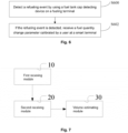
- This application further provides a device configured to implement the above detection method. The device includes a
first receiving module 10. - The
first receiving module 10 is configured to receive a fuel quantity change parameter calibrated by a user at a smart terminal. - Specifically, the operation of receiving the fuel quantity change parameter calibrated by the user at the smart terminal includes the following operations.
- Whether the smart terminal has a user calibration operation is monitored.
- If yes, the fuel quantity change parameter is generated according to the user calibration operation.
- The fuel quantity change parameter is received.
- The smart terminal may be portable devices, such as a mobile phone and a tablet computer, or may be a personal computer (pc). In this embodiment, the mobile phone is preferred. Application processing software is installed on the mobile phone, and by means of the software, the user may calibrate the fuel quantity change parameter. Specifically, the user opens the software to enter an interactive interface, and inputs fuel quantity, namely the fuel quantity change parameter, of this fueling in the interactive interface through calibration operation. After the fuel quantity change parameter is acquired, the fuel quantity change parameter is sent to the server. In this way, parameter guarantee may be provided for the volume estimation of the server.
- In this embodiment, the smart terminal communicates with the server in wireless transmission modes, such as GPRS, 3G, 4G, and WiFi.
- It is to be noted that, in this embodiment, the measurement method is only applicable for volume measurement of regular fuel tanks, such as a cuboid fuel tank and a cube fuel tank.
- Preferably, the operation before receiving the fuel quantity change parameter calibrated by the user at the smart terminal further includes the following operations.
- A refueling event is detected by using a fuel tank cap detecting device on the fueling terminal.
- If the refueling event is detected, the fuel quantity change parameter calibrated by the user at the smart terminal is received.
- Only after a certain condition is met, the receiving of the fuel quantity change parameter can be triggered.
- In this embodiment, preferably, when the fuel tank cap detecting device on the fueling terminal detects the refueling event, a prompt message is sent to the smart terminal with a binding relationship, to prompt the user to start refueling. After receiving the message, the user may click the prompt message, so that the application processing software can be automatically opened, then corresponding calibration operation is performed to upload the fuel quantity change parameter to the server.
- If the fuel tank cap detecting device on the fueling terminal does not detect the refueling event, a link of a stopping reason for no refueling event is output at the smart terminal. In this embodiment, preferably, after receiving the stopping reason, the user may click the link to directly open the software, so as to enter a software interface to check the stopping reason. In this way, the user may continue to operate to restart a program after checking and eliminating the reason on site.
- When there is the refueling event, the prompt message may be actively sent. Prompt personnel complete the uploading of the fuel quantity change parameter through the operation of the application processing software. When there is no refueling events, the procedure is stopped, and the uploading of the fuel quantity change parameter is completed only after the user opens the software to operate.
- A
second receiving module 20 is configured to receive the measurement parameter collected from the fueling terminal through the sensor according to the preset frequency. - Specifically, the operation of receiving the measurement parameter collected from the fueling terminal through the sensor according to the preset frequency includes the following operations.
- A parameter set of liquid level pressure collected from the fueling terminal through the sensor according to the preset frequency is received.
- The parameter set of the liquid level pressure is recorded and stored.
- The fuel quantity change parameter (fuel quantity) is one of parameters of the estimated volume of the fuel tank, so that it requires a plurality of measurement parameters during refueling to realize the estimation of the volume of the fuel tank. The sensor can periodically collect the measurement parameters. That is to say, the liquid level pressure is detected and recorded every a period of time, so as to acquire one parameter set of the liquid level pressure. The liquid level pressure in the parameter set of the liquid level pressure is stored one by one. After refueling is finished, the liquid level pressure is uniformly uploaded to the server, to estimate the volume of the fuel tank.
- A
volume estimating module 30 is configured to input the fuel quantity change parameter and the measurement parameter into the preset volume calibration model, and estimate the volume of the fuel tank. - The volume calibration model at least includes a full fueling liquid level pressure value and an air liquid level pressure value.
- The air liquid level pressure value is constant to any fuel tanks. Thus, it only needs to be preset in a volume calibration model as a default parameter at factory. The air liquid level pressure value is an essential parameter during volume estimation.
- The full fueling liquid level pressure value may vary with the height of the fuel tank. Therefore, when refueling is performed at the first time, personnel needs to be reminded that it is in a fueling state, and a measured maximum liquid level pressure value acts as the full fueling liquid level pressure value. The full fueling liquid level pressure value is an essential parameter during volume estimation.
- After the two parameters are acquired in advance, by combining the measurement parameter, the fuel quantity change parameter and the preset volume calibration model, the volume of the fuel tank is estimated.
- Preferably, the
volume estimating module 30 is configured to perform the following operations. - A minimum liquid level pressure and a maximum liquid level pressure in the measurement parameter are extracted.
- The correspondence between the hydraulic pressure and the volume percentage is determined according to the variation of the liquid level pressure with time.
- A capacity change percentage is estimated according to the minimum liquid level pressure, the maximum liquid level pressure and the correspondence between the hydraulic pressure and the volume percentage.
- The volume of the fuel tank is inversely deduced according to a fuel quantity change percentage and the fuel quantity change parameter.
- Specifically, the capacity change percentage is related to the minimum liquid level pressure and the maximum liquid level pressure, and is unrelated to the refueling process. Thus, only the minimum liquid level pressure (the liquid level pressure before refueling) and the maximum liquid level pressure (the liquid level pressure after refueling) are required to be extracted. In this way, in this embodiment, whether a refueling rate is constant is not limited. The constant refueling rate may be adopted, or the non-constant refueling rate may also be adopted. For ease of description, in this embodiment, assuming the refueling rate of the refueling gun is constant, Δv generated in Δt is the same. If a collection rate of hardware is constant, the Δt between two adjacent hydraulic pressure data points is the same, and the corresponding Δv is the same.
- Pi{1 ...n} is set as a hydraulic pressure value collected at a fixed frequency at a refueling phase. The hydraulic pressure value in air is known as P0. The bottom shape of the fuel tank is regular. Pn is a collected maximum hydraulic pressure value point. P1 is a minimum hydraulic pressure value point collected at one time.
- Polynomial fitting (Pi, i-1) is performed by using Pi{1...m}(m<n) to acquire a slope k and an offset b. Subscript Index0 corresponding to P0 is calculated by using the k, the b and the hydraulic pressure value P0 in air.
- The variation of the liquid level pressure with time is shown as follows: Index0 = P0*k + b.
- Then, a distance from P1 to P0 accounts a percentage Pct1 of a distance from Pn to P0 is calculated.

- In this way, a corresponding percentage increment ΔPct between the adjacent hydraulic pressure values is obtained.

- A volume percentage Pcti is acquired finally.

- According to Pcti = Pct1 + ΔPct * (i-1) (i = 1..n), (Pi, Pcti) may be determined to achieve one-to-one correspondence, so as to form a complete correspondence between the hydraulic pressure values and the percentages.
- The minimum and maximum liquid level pressure in the measurement parameter are extracted. Referring to the correspondence between the hydraulic pressure values and the percentages, the percentage of capacity change can be determined, and then the volume of the fuel tank can be inversely deduced. Therefore, accurate and intelligent calculation of the volume of the fuel tank is realized, and further fuel tank metering management is achieved.
- Preferably, the device further includes a
monitoring module 40. Themonitoring module 40 is configured to perform the following operations. - The maximum liquid level pressure in the measurement parameter is extracted.
- The correspondence between the hydraulic pressure and the volume percentage is determined according to the variation of the liquid level pressure with time.
- A current capacity percentage is estimated according to the maximum liquid level pressure and the correspondence between the hydraulic pressure and the volume percentage.
- A current fuel quantity is calculated according to the volume of the fuel tank and the current capacity percentage.
- Through the utilization of the variation of the liquid level pressure with time: Index0 = P0 * k + b, (Pi, Pcti) may be determined to achieve one-to-one correspondence, so as to form a complete correspondence between the hydraulic pressure values and the percentages.
- Referring to the correspondence, by combining the maximum liquid level pressure, the current capacity percentage can be determined, and the current fuel quantity may be calculated by multiplying the percentage by the volume of the fuel tank.
- The calculation of the current fuel quantity may achieve further fuel tank metering management of fuel theft and fuel leakage.
- It may be learned from the above description that, in this application, the following technical effects are realized.
- According to the method and device for detecting the fuel tank, and the server in the embodiments of this application, the fuel quantity change parameter calibrated by the user at the smart terminal is received. The measurement parameter collected from the fueling terminal through the sensor according to the preset frequency is received. The fuel quantity change parameter and the measurement parameter are input into the preset volume calibration model, and the volume of the fuel tank is estimated. The volume calibration model at least includes a full fueling liquid level pressure value and an air liquid level pressure value. In this way, a purpose that the volumes of different types of the fuel tanks may be intelligently estimated is achieved. Therefore, a technical effect of fuel tank metering management is realized, thereby resolving the technical problems of poor fuel tank metering management because the volume of the same type of fuel tank cannot be intelligently estimated.
- It is apparent that those skilled in the art should understand that the above mentioned modules or steps of this application may be implemented by a general computing device, and may also be gathered together on a single computing device or distributed in network composed of multiple computing devices. Optionally, the above mentioned modules or steps of this application may be implemented with program codes executable by the computing device, so that may be stored in a storage device for execution by the computing device, or can be fabricated into individual integrated circuit modules respectively, or multiple modules or steps thereof are fabricated into a single integrated circuit module for implementation. In this way, this application is not limited to any specific combination of hardware and software.
Claims (10)
- A method for measuring the volume of a fuel tank, comprising:receiving a fuel quantity change parameter calibrated by a user at a smart terminal (S100);receiving a measured liquid level pressure value collected from a fueling terminal through a sensor according to a preset frequency (S102); andinputting the fuel quantity change parameter and the measured liquid level pressure value into a preset volume calibration model and estimating the volume of the fuel tank (S104),characterized in thatthe volume calibration model at least comprises a maximum liquid level pressure value, when the fuel tank is full, and a minimum liquid level pressure value, when the fuel tank is empty, wherein these pressure values are extracted from the measured liquid level pressure (S400, S500).
- The as claimed in claim 1, wherein the operation of receiving the fuel quantity change parameter calibrated by the user at the smart terminal (S100) comprises:monitoring whether the smart terminal has a user calibration operation (S200);if yes, generating the fuel quantity change parameter according to the user calibration operation (S202); andreceiving the fuel quantity change parameter (S204).
- The method as claimed in claim 1, wherein the operation of receiving the measured liquid level pressure value collected from the fueling terminal through the sensor according to the preset frequency (S102) comprises:receiving a parameter set of liquid level pressure collected from the fueling terminal through the sensor according to the preset frequency (S300); andrecording and storing the parameter set of the liquid level pressure (S302).
- The method as claimed in claim 1, wherein the operation of inputting the fuel quantity change parameter and the measured liquid level pressure value into the preset volume calibration model and estimating the volume of the fuel tank comprises:determining a correspondence between hydraulic pressure and a volume percentage according to variation of the liquid level pressure with time (S402);estimating a capacity change percentage according to the minimum liquid level pressure, the maximum liquid level pressure and the correspondence between the hydraulic pressure and the volume percentage (S404); andinversely deducing the volume of the fuel tank according to the capacity change percentage and the fuel quantity change parameter (S406).
- The method as claimed in claim 1, wherein the operation after inputting the fuel quantity change parameter and the measured liquid level pressure value into the preset volume calibration model and estimating the volume of the fuel tank further comprises:determining the correspondence between the hydraulic pressure and the volume percentage according to the variation of the liquid level pressure with time (S502);estimating a current capacity percentage according to the maximum liquid level pressure and the correspondence between the hydraulic pressure and the volume percentage (S504); andcalculating a current fuel quantity according to the volume of the fuel tank and the current capacity percentage (S506).
- The method as claimed in claim 1, wherein the operation before receiving the fuel quantity change parameter calibrated by the user at the smart terminal further comprises:detecting a refueling event by using a fuel tank cap detecting device on the fueling terminal (S600); andif the refueling event is detected, receiving the fuel quantity change parameter calibrated by the user at the smart terminal (S602).
- A device for measuring the volume of a fuel tank, comprising:a first receiving module (10), configured to receive a fuel quantity change parameter calibrated by a user at a smart terminal;a second receiving module (20), configured to receive a measured liquid level pressure value collected from a fueling terminal through a sensor according to a preset frequency, anda volume estimating module (30), configured to input the fuel quantity change parameter and the measured liquid level pressure value into a preset volume calibration model, and estimate the volume of the fuel tank,characterized in thatthe volume calibration model at least comprises a maximum liquid level pressure value, when the fuel tank is full, and a minimum liquid level pressure value, when the fuel tank is empty,and in that the second receiving module is configured to extract the minimum liquid level pressure and the maximal liquid level pressure from the measured liquid level pressure.
- The measurement device as claimed in claim 7, wherein the volume estimating module (30) is configured to perform as follows:determining a correspondence between hydraulic pressure and volume percentage according to variation of liquid level pressure with time (S402);estimating a capacity change percentage according to the minimum liquid level pressure, the maximum liquid level pressure and the correspondence between the hydraulic pressure and the volume percentage (S404); andinversely deducing the volume of the fuel tank according to a fuel quantity change percentage and the fuel quantity change parameter (S406).
- The measurement device as claimed in claim 7, wherein the detection device further comprises a monitoring module, and the monitoring module is configured to perform as follows:determining the correspondence between the hydraulic pressure and the volume percentage according to the variation of the liquid level pressure with time;estimating a current capacity percentage according to the maximum liquid level pressure and the correspondence between the hydraulic pressure and the volume percentage; andcalculating a current fuel quantity according to the volume of the fuel tank and the current capacity percentage.
- A server, configured to perform the measurement method according to any one of claims 1 to 6.
Applications Claiming Priority (2)
| Application Number | Priority Date | Filing Date | Title |
|---|---|---|---|
| CN201910573336.XA CN110307879B (en) | 2019-06-27 | 2019-06-27 | Detection method and device for oil tank and server |
| PCT/CN2020/086887 WO2020259051A1 (en) | 2019-06-27 | 2020-04-25 | Method and apparatus for measuring fuel tank and server |
Publications (3)
| Publication Number | Publication Date |
|---|---|
| EP3967990A1 EP3967990A1 (en) | 2022-03-16 |
| EP3967990A4 EP3967990A4 (en) | 2023-04-19 |
| EP3967990B1 true EP3967990B1 (en) | 2024-04-10 |
Family
ID=68077831
Family Applications (1)
| Application Number | Title | Priority Date | Filing Date |
|---|---|---|---|
| EP20831909.5A Active EP3967990B1 (en) | 2019-06-27 | 2020-04-25 | Method and apparatus for measuring fuel tank, and server |
Country Status (4)
| Country | Link |
|---|---|
| US (1) | US20220236097A1 (en) |
| EP (1) | EP3967990B1 (en) |
| CN (1) | CN110307879B (en) |
| WO (1) | WO2020259051A1 (en) |
Families Citing this family (7)
| Publication number | Priority date | Publication date | Assignee | Title |
|---|---|---|---|---|
| CN110307879B (en) * | 2019-06-27 | 2021-08-24 | 南京智鹤电子科技有限公司 | Detection method and device for oil tank and server |
| CN111141348A (en) * | 2019-11-28 | 2020-05-12 | 郑州众智科技股份有限公司 | Method and system for calculating oil consumption parameter based on generator set controller |
| CN111924791B (en) * | 2020-07-22 | 2022-03-22 | 南京智鹤电子科技有限公司 | Oil tank oil level calibration method and device and electronic equipment |
| CN112284753B (en) * | 2020-12-28 | 2021-03-12 | 中国航发上海商用航空发动机制造有限责任公司 | Method and device for measuring and analyzing flow of gas compressor test and gas compressor test system |
| CN115750162B (en) * | 2022-12-07 | 2025-09-23 | 亚普汽车部件股份有限公司 | Fuel system control method and fuel system |
| MA60446B1 (en) * | 2023-05-16 | 2025-02-28 | Université Abdelmalek Essaâdi | Device for controlling the filling of a tank. |
| CN121655738A (en) * | 2026-02-05 | 2026-03-13 | 舟山市质量技术监督检测研究院 | A method for measuring the temperature of a liquid nitrogen biological container |
Citations (2)
| Publication number | Priority date | Publication date | Assignee | Title |
|---|---|---|---|---|
| EP0689038B1 (en) * | 1994-06-21 | 2002-02-20 | Johnson & Johnson Clinical Diagnostics, Inc. | Non-invasive method of determining residual liquid reagents |
| EP2301404B1 (en) * | 2009-07-31 | 2016-08-17 | Miele & Cie. KG | Method for displaying the fill level of a vacuum cleaner bag and control device for carrying out the method |
Family Cites Families (21)
| Publication number | Priority date | Publication date | Assignee | Title |
|---|---|---|---|---|
| RU2047108C1 (en) * | 1993-02-03 | 1995-10-27 | Научно-технический центр "Нефтепромдиагностика" Научно-исследовательского института разработки и эксплуатации нефтепромысловых труб | Method and ultrasonic device to determine capacity and graduate tanks |
| US5665895A (en) * | 1995-06-02 | 1997-09-09 | Veeder-Root Company | Apparatus and method for calibrating a storage tank |
| JPH1090295A (en) * | 1996-09-11 | 1998-04-10 | Yokogawa Electric Corp | Flow velocity calculator |
| US6484088B1 (en) * | 1999-05-04 | 2002-11-19 | Ssi Technologies, Inc. | Fuel optimization system with improved fuel level sensor |
| KR20040096936A (en) * | 2004-10-08 | 2004-11-17 | 차경석 | The ultrasonic instrument with zero target |
| US7305875B1 (en) * | 2005-03-31 | 2007-12-11 | Gerald Pindus | Method and apparatus for measuring the volume of fuel in a tank |
| CN102072752B (en) * | 2010-10-28 | 2012-05-16 | 中国农业大学 | Non-intrusive high-precision automobile fuel consumption measurement system |
| CN203063665U (en) * | 2012-12-27 | 2013-07-17 | 上海通用汽车有限公司 | Refueling vent pipe, fuel tank and refueling system composed of refueling vent pipe and fuel tank |
| CN203534675U (en) * | 2013-10-17 | 2014-04-09 | 亚普汽车部件股份有限公司 | Device for measuring size and height of fuel tank and output resistance feature of oil pump |
| CN103674167B (en) * | 2013-12-25 | 2017-01-18 | 深圳市易流科技有限公司 | Oil mass accurate calibration instrument and implementation method thereof |
| CN103727991B (en) * | 2014-01-17 | 2016-08-17 | 北京航空航天大学 | Vehicle fuel tank fuel quantity calibration system and scaling method |
| CN103791979B (en) * | 2014-01-25 | 2017-01-11 | 长城汽车股份有限公司 | High-precision fuel tank fuel quantity measuring device |
| GB2527269A (en) * | 2014-03-24 | 2015-12-23 | Empower Energy Systems Ltd | A method and apparatus for monitoring the volume of oil in an oil storage tank |
| CN104634409B (en) * | 2015-02-06 | 2019-03-26 | 中国运载火箭技术研究院 | A kind of 5M grades of tank volumetric calibration equipment and method |
| US9790080B1 (en) * | 2016-10-11 | 2017-10-17 | Fuel Automation Station, LLC | Mobile distribution station with fail-safes |
| CN106908115B (en) * | 2017-02-24 | 2019-11-26 | 北京中位科技有限公司 | Vehicle fuel tank fuel quantity scaling method and system |
| CN106908113B (en) * | 2017-02-24 | 2021-01-08 | 北京中位科技有限公司 | Vehicle oil tank oil quantity monitoring method and system |
| US10442545B2 (en) * | 2017-04-18 | 2019-10-15 | Simmonds Precision Products, Inc. | Liquid measurement system for a tank |
| CN107860434B (en) * | 2017-10-31 | 2019-06-28 | 安徽江淮汽车集团股份有限公司 | A kind of scaling method of fuel tank for automobile calibration system |
| CN108444563A (en) * | 2018-05-16 | 2018-08-24 | 河北亿程交通科技有限公司 | Fuel tank fuel quantity detection device based on pressure balance type |
| CN110307879B (en) * | 2019-06-27 | 2021-08-24 | 南京智鹤电子科技有限公司 | Detection method and device for oil tank and server |
-
2019
- 2019-06-27 CN CN201910573336.XA patent/CN110307879B/en active Active
-
2020
- 2020-04-25 US US17/618,490 patent/US20220236097A1/en not_active Abandoned
- 2020-04-25 WO PCT/CN2020/086887 patent/WO2020259051A1/en not_active Ceased
- 2020-04-25 EP EP20831909.5A patent/EP3967990B1/en active Active
Patent Citations (2)
| Publication number | Priority date | Publication date | Assignee | Title |
|---|---|---|---|---|
| EP0689038B1 (en) * | 1994-06-21 | 2002-02-20 | Johnson & Johnson Clinical Diagnostics, Inc. | Non-invasive method of determining residual liquid reagents |
| EP2301404B1 (en) * | 2009-07-31 | 2016-08-17 | Miele & Cie. KG | Method for displaying the fill level of a vacuum cleaner bag and control device for carrying out the method |
Also Published As
| Publication number | Publication date |
|---|---|
| CN110307879A (en) | 2019-10-08 |
| WO2020259051A1 (en) | 2020-12-30 |
| EP3967990A4 (en) | 2023-04-19 |
| US20220236097A1 (en) | 2022-07-28 |
| EP3967990A1 (en) | 2022-03-16 |
| CN110307879B (en) | 2021-08-24 |
Similar Documents
| Publication | Publication Date | Title |
|---|---|---|
| EP3967990B1 (en) | Method and apparatus for measuring fuel tank, and server | |
| US5400253A (en) | Automated statistical inventory reconcilation system for convenience stores and auto/truck service stations | |
| US20060111851A1 (en) | Fuel theft detection system and method | |
| US20190040564A1 (en) | Method for monitoring water consumption of washing machine, washing machine, and washing machine system | |
| WO1997046855A1 (en) | Method and apparatus for monitoring operational performance of fluid storage systems | |
| WO2012141812A1 (en) | Event monitoring and detection in liquid level monitoring system | |
| CN103017854B (en) | Oil mass computing method, device and supervisory system | |
| WO2011051949A1 (en) | Fuel tank monitoring system and method | |
| US11397909B2 (en) | Long term sensor monitoring for remote assets | |
| CN111061238A (en) | Production safety monitoring method, device, equipment and medium for lithium battery | |
| KR100944043B1 (en) | Remote flow meter reading system with data logger device and method thereof | |
| CN116034252A (en) | Method and system for determining the volume of a liquid | |
| AU2014224190A2 (en) | Fluid monitoring system | |
| CN109870211B (en) | Method and device for detecting rice amount in rice storage equipment and rice barrel | |
| CN109573934A (en) | Engineering truck oil management method and system | |
| CN111622285B (en) | Energy efficiency detection system and method for excavator and excavator | |
| CN212963557U (en) | Calibration device | |
| CN103267550A (en) | Fuel consumption testing device for excavators | |
| CN110220557B (en) | Detection method and device for oil tank and server | |
| JP2011149829A (en) | Leakage detector | |
| CN109589475A (en) | The accuracy automatic checkout system and method for infusion equipment | |
| KR101504981B1 (en) | Lubricator, terminal for inspection of lubricator, server for managing lubricator, and lubricator inspection system comprising the same | |
| CN112577525A (en) | Method, device and system for detecting availability of level box of nuclear power station | |
| JP2002019900A (en) | Storage level management system | |
| CN215677230U (en) | Mobile oiling machine calibrating device |
Legal Events
| Date | Code | Title | Description |
|---|---|---|---|
| STAA | Information on the status of an ep patent application or granted ep patent |
Free format text: STATUS: THE INTERNATIONAL PUBLICATION HAS BEEN MADE |
|
| PUAI | Public reference made under article 153(3) epc to a published international application that has entered the european phase |
Free format text: ORIGINAL CODE: 0009012 |
|
| STAA | Information on the status of an ep patent application or granted ep patent |
Free format text: STATUS: REQUEST FOR EXAMINATION WAS MADE |
|
| 17P | Request for examination filed |
Effective date: 20211209 |
|
| AK | Designated contracting states |
Kind code of ref document: A1 Designated state(s): AL AT BE BG CH CY CZ DE DK EE ES FI FR GB GR HR HU IE IS IT LI LT LU LV MC MK MT NL NO PL PT RO RS SE SI SK SM TR |
|
| DAV | Request for validation of the european patent (deleted) | ||
| DAX | Request for extension of the european patent (deleted) | ||
| A4 | Supplementary search report drawn up and despatched |
Effective date: 20230322 |
|
| RIC1 | Information provided on ipc code assigned before grant |
Ipc: G01F 23/18 20060101ALN20230316BHEP Ipc: B60K 15/03 20060101ALI20230316BHEP Ipc: G01F 25/00 20220101ALI20230316BHEP Ipc: G01F 23/00 20220101ALI20230316BHEP Ipc: G01F 17/00 20060101AFI20230316BHEP |
|
| GRAP | Despatch of communication of intention to grant a patent |
Free format text: ORIGINAL CODE: EPIDOSNIGR1 |
|
| STAA | Information on the status of an ep patent application or granted ep patent |
Free format text: STATUS: GRANT OF PATENT IS INTENDED |
|
| RIC1 | Information provided on ipc code assigned before grant |
Ipc: G01F 23/18 20060101ALN20231002BHEP Ipc: G01F 22/02 20060101ALI20231002BHEP Ipc: B60K 15/03 20060101ALI20231002BHEP Ipc: G01F 25/00 20220101ALI20231002BHEP Ipc: G01F 23/00 20220101ALI20231002BHEP Ipc: G01F 17/00 20060101AFI20231002BHEP |
|
| INTG | Intention to grant announced |
Effective date: 20231106 |
|
| GRAS | Grant fee paid |
Free format text: ORIGINAL CODE: EPIDOSNIGR3 |
|
| GRAA | (expected) grant |
Free format text: ORIGINAL CODE: 0009210 |
|
| STAA | Information on the status of an ep patent application or granted ep patent |
Free format text: STATUS: THE PATENT HAS BEEN GRANTED |
|
| AK | Designated contracting states |
Kind code of ref document: B1 Designated state(s): AL AT BE BG CH CY CZ DE DK EE ES FI FR GB GR HR HU IE IS IT LI LT LU LV MC MK MT NL NO PL PT RO RS SE SI SK SM TR |
|
| REG | Reference to a national code |
Ref country code: GB Ref legal event code: FG4D |
|
| REG | Reference to a national code |
Ref country code: CH Ref legal event code: EP |
|
| REG | Reference to a national code |
Ref country code: DE Ref legal event code: R096 Ref document number: 602020028901 Country of ref document: DE |
|
| REG | Reference to a national code |
Ref country code: IE Ref legal event code: FG4D |
|
| REG | Reference to a national code |
Ref country code: LT Ref legal event code: MG9D |
|
| REG | Reference to a national code |
Ref country code: NL Ref legal event code: MP Effective date: 20240410 |
|
| REG | Reference to a national code |
Ref country code: AT Ref legal event code: MK05 Ref document number: 1675336 Country of ref document: AT Kind code of ref document: T Effective date: 20240410 |
|
| PG25 | Lapsed in a contracting state [announced via postgrant information from national office to epo] |
Ref country code: NL Free format text: LAPSE BECAUSE OF FAILURE TO SUBMIT A TRANSLATION OF THE DESCRIPTION OR TO PAY THE FEE WITHIN THE PRESCRIBED TIME-LIMIT Effective date: 20240410 |
|
| PG25 | Lapsed in a contracting state [announced via postgrant information from national office to epo] |
Ref country code: NL Free format text: LAPSE BECAUSE OF FAILURE TO SUBMIT A TRANSLATION OF THE DESCRIPTION OR TO PAY THE FEE WITHIN THE PRESCRIBED TIME-LIMIT Effective date: 20240410 |
|
| PG25 | Lapsed in a contracting state [announced via postgrant information from national office to epo] |
Ref country code: IS Free format text: LAPSE BECAUSE OF FAILURE TO SUBMIT A TRANSLATION OF THE DESCRIPTION OR TO PAY THE FEE WITHIN THE PRESCRIBED TIME-LIMIT Effective date: 20240810 |
|
| PG25 | Lapsed in a contracting state [announced via postgrant information from national office to epo] |
Ref country code: BG Free format text: LAPSE BECAUSE OF FAILURE TO SUBMIT A TRANSLATION OF THE DESCRIPTION OR TO PAY THE FEE WITHIN THE PRESCRIBED TIME-LIMIT Effective date: 20240410 |
|
| PG25 | Lapsed in a contracting state [announced via postgrant information from national office to epo] |
Ref country code: HR Free format text: LAPSE BECAUSE OF FAILURE TO SUBMIT A TRANSLATION OF THE DESCRIPTION OR TO PAY THE FEE WITHIN THE PRESCRIBED TIME-LIMIT Effective date: 20240410 Ref country code: FI Free format text: LAPSE BECAUSE OF FAILURE TO SUBMIT A TRANSLATION OF THE DESCRIPTION OR TO PAY THE FEE WITHIN THE PRESCRIBED TIME-LIMIT Effective date: 20240410 |
|
| PG25 | Lapsed in a contracting state [announced via postgrant information from national office to epo] |
Ref country code: GR Free format text: LAPSE BECAUSE OF FAILURE TO SUBMIT A TRANSLATION OF THE DESCRIPTION OR TO PAY THE FEE WITHIN THE PRESCRIBED TIME-LIMIT Effective date: 20240711 |
|
| PG25 | Lapsed in a contracting state [announced via postgrant information from national office to epo] |
Ref country code: PT Free format text: LAPSE BECAUSE OF FAILURE TO SUBMIT A TRANSLATION OF THE DESCRIPTION OR TO PAY THE FEE WITHIN THE PRESCRIBED TIME-LIMIT Effective date: 20240812 |
|
| PG25 | Lapsed in a contracting state [announced via postgrant information from national office to epo] |
Ref country code: ES Free format text: LAPSE BECAUSE OF FAILURE TO SUBMIT A TRANSLATION OF THE DESCRIPTION OR TO PAY THE FEE WITHIN THE PRESCRIBED TIME-LIMIT Effective date: 20240410 |
|
| PG25 | Lapsed in a contracting state [announced via postgrant information from national office to epo] |
Ref country code: AT Free format text: LAPSE BECAUSE OF FAILURE TO SUBMIT A TRANSLATION OF THE DESCRIPTION OR TO PAY THE FEE WITHIN THE PRESCRIBED TIME-LIMIT Effective date: 20240410 |
|
| PG25 | Lapsed in a contracting state [announced via postgrant information from national office to epo] |
Ref country code: PL Free format text: LAPSE BECAUSE OF FAILURE TO SUBMIT A TRANSLATION OF THE DESCRIPTION OR TO PAY THE FEE WITHIN THE PRESCRIBED TIME-LIMIT Effective date: 20240410 |
|
| PG25 | Lapsed in a contracting state [announced via postgrant information from national office to epo] |
Ref country code: LV Free format text: LAPSE BECAUSE OF FAILURE TO SUBMIT A TRANSLATION OF THE DESCRIPTION OR TO PAY THE FEE WITHIN THE PRESCRIBED TIME-LIMIT Effective date: 20240410 |
|
| PG25 | Lapsed in a contracting state [announced via postgrant information from national office to epo] |
Ref country code: PT Free format text: LAPSE BECAUSE OF FAILURE TO SUBMIT A TRANSLATION OF THE DESCRIPTION OR TO PAY THE FEE WITHIN THE PRESCRIBED TIME-LIMIT Effective date: 20240812 Ref country code: PL Free format text: LAPSE BECAUSE OF FAILURE TO SUBMIT A TRANSLATION OF THE DESCRIPTION OR TO PAY THE FEE WITHIN THE PRESCRIBED TIME-LIMIT Effective date: 20240410 Ref country code: NO Free format text: LAPSE BECAUSE OF FAILURE TO SUBMIT A TRANSLATION OF THE DESCRIPTION OR TO PAY THE FEE WITHIN THE PRESCRIBED TIME-LIMIT Effective date: 20240710 Ref country code: LV Free format text: LAPSE BECAUSE OF FAILURE TO SUBMIT A TRANSLATION OF THE DESCRIPTION OR TO PAY THE FEE WITHIN THE PRESCRIBED TIME-LIMIT Effective date: 20240410 Ref country code: IS Free format text: LAPSE BECAUSE OF FAILURE TO SUBMIT A TRANSLATION OF THE DESCRIPTION OR TO PAY THE FEE WITHIN THE PRESCRIBED TIME-LIMIT Effective date: 20240810 Ref country code: HR Free format text: LAPSE BECAUSE OF FAILURE TO SUBMIT A TRANSLATION OF THE DESCRIPTION OR TO PAY THE FEE WITHIN THE PRESCRIBED TIME-LIMIT Effective date: 20240410 Ref country code: GR Free format text: LAPSE BECAUSE OF FAILURE TO SUBMIT A TRANSLATION OF THE DESCRIPTION OR TO PAY THE FEE WITHIN THE PRESCRIBED TIME-LIMIT Effective date: 20240711 Ref country code: FI Free format text: LAPSE BECAUSE OF FAILURE TO SUBMIT A TRANSLATION OF THE DESCRIPTION OR TO PAY THE FEE WITHIN THE PRESCRIBED TIME-LIMIT Effective date: 20240410 Ref country code: ES Free format text: LAPSE BECAUSE OF FAILURE TO SUBMIT A TRANSLATION OF THE DESCRIPTION OR TO PAY THE FEE WITHIN THE PRESCRIBED TIME-LIMIT Effective date: 20240410 Ref country code: BG Free format text: LAPSE BECAUSE OF FAILURE TO SUBMIT A TRANSLATION OF THE DESCRIPTION OR TO PAY THE FEE WITHIN THE PRESCRIBED TIME-LIMIT Effective date: 20240410 Ref country code: AT Free format text: LAPSE BECAUSE OF FAILURE TO SUBMIT A TRANSLATION OF THE DESCRIPTION OR TO PAY THE FEE WITHIN THE PRESCRIBED TIME-LIMIT Effective date: 20240410 Ref country code: RS Free format text: LAPSE BECAUSE OF FAILURE TO SUBMIT A TRANSLATION OF THE DESCRIPTION OR TO PAY THE FEE WITHIN THE PRESCRIBED TIME-LIMIT Effective date: 20240710 |
|
| REG | Reference to a national code |
Ref country code: DE Ref legal event code: R119 Ref document number: 602020028901 Country of ref document: DE |
|
| REG | Reference to a national code |
Ref country code: CH Ref legal event code: PL |
|
| PG25 | Lapsed in a contracting state [announced via postgrant information from national office to epo] |
Ref country code: LU Free format text: LAPSE BECAUSE OF NON-PAYMENT OF DUE FEES Effective date: 20240425 |
|
| REG | Reference to a national code |
Ref country code: BE Ref legal event code: MM Effective date: 20240430 |
|
| PG25 | Lapsed in a contracting state [announced via postgrant information from national office to epo] |
Ref country code: LU Free format text: LAPSE BECAUSE OF NON-PAYMENT OF DUE FEES Effective date: 20240425 |
|
| PG25 | Lapsed in a contracting state [announced via postgrant information from national office to epo] |
Ref country code: DE Free format text: LAPSE BECAUSE OF NON-PAYMENT OF DUE FEES Effective date: 20241105 |
|
| PG25 | Lapsed in a contracting state [announced via postgrant information from national office to epo] |
Ref country code: DK Free format text: LAPSE BECAUSE OF FAILURE TO SUBMIT A TRANSLATION OF THE DESCRIPTION OR TO PAY THE FEE WITHIN THE PRESCRIBED TIME-LIMIT Effective date: 20240410 |
|
| PG25 | Lapsed in a contracting state [announced via postgrant information from national office to epo] |
Ref country code: BE Free format text: LAPSE BECAUSE OF NON-PAYMENT OF DUE FEES Effective date: 20240430 |
|
| PG25 | Lapsed in a contracting state [announced via postgrant information from national office to epo] |
Ref country code: EE Free format text: LAPSE BECAUSE OF FAILURE TO SUBMIT A TRANSLATION OF THE DESCRIPTION OR TO PAY THE FEE WITHIN THE PRESCRIBED TIME-LIMIT Effective date: 20240410 |
|
| PG25 | Lapsed in a contracting state [announced via postgrant information from national office to epo] |
Ref country code: CZ Free format text: LAPSE BECAUSE OF FAILURE TO SUBMIT A TRANSLATION OF THE DESCRIPTION OR TO PAY THE FEE WITHIN THE PRESCRIBED TIME-LIMIT Effective date: 20240410 |
|
| PG25 | Lapsed in a contracting state [announced via postgrant information from national office to epo] |
Ref country code: SK Free format text: LAPSE BECAUSE OF FAILURE TO SUBMIT A TRANSLATION OF THE DESCRIPTION OR TO PAY THE FEE WITHIN THE PRESCRIBED TIME-LIMIT Effective date: 20240410 Ref country code: RO Free format text: LAPSE BECAUSE OF FAILURE TO SUBMIT A TRANSLATION OF THE DESCRIPTION OR TO PAY THE FEE WITHIN THE PRESCRIBED TIME-LIMIT Effective date: 20240410 |
|
| PG25 | Lapsed in a contracting state [announced via postgrant information from national office to epo] |
Ref country code: SM Free format text: LAPSE BECAUSE OF FAILURE TO SUBMIT A TRANSLATION OF THE DESCRIPTION OR TO PAY THE FEE WITHIN THE PRESCRIBED TIME-LIMIT Effective date: 20240410 |
|
| PG25 | Lapsed in a contracting state [announced via postgrant information from national office to epo] |
Ref country code: SM Free format text: LAPSE BECAUSE OF FAILURE TO SUBMIT A TRANSLATION OF THE DESCRIPTION OR TO PAY THE FEE WITHIN THE PRESCRIBED TIME-LIMIT Effective date: 20240410 Ref country code: SK Free format text: LAPSE BECAUSE OF FAILURE TO SUBMIT A TRANSLATION OF THE DESCRIPTION OR TO PAY THE FEE WITHIN THE PRESCRIBED TIME-LIMIT Effective date: 20240410 Ref country code: RO Free format text: LAPSE BECAUSE OF FAILURE TO SUBMIT A TRANSLATION OF THE DESCRIPTION OR TO PAY THE FEE WITHIN THE PRESCRIBED TIME-LIMIT Effective date: 20240410 Ref country code: EE Free format text: LAPSE BECAUSE OF FAILURE TO SUBMIT A TRANSLATION OF THE DESCRIPTION OR TO PAY THE FEE WITHIN THE PRESCRIBED TIME-LIMIT Effective date: 20240410 Ref country code: DK Free format text: LAPSE BECAUSE OF FAILURE TO SUBMIT A TRANSLATION OF THE DESCRIPTION OR TO PAY THE FEE WITHIN THE PRESCRIBED TIME-LIMIT Effective date: 20240410 Ref country code: DE Free format text: LAPSE BECAUSE OF NON-PAYMENT OF DUE FEES Effective date: 20241105 Ref country code: CZ Free format text: LAPSE BECAUSE OF FAILURE TO SUBMIT A TRANSLATION OF THE DESCRIPTION OR TO PAY THE FEE WITHIN THE PRESCRIBED TIME-LIMIT Effective date: 20240410 Ref country code: BE Free format text: LAPSE BECAUSE OF NON-PAYMENT OF DUE FEES Effective date: 20240430 Ref country code: CH Free format text: LAPSE BECAUSE OF NON-PAYMENT OF DUE FEES Effective date: 20240430 Ref country code: MC Free format text: LAPSE BECAUSE OF FAILURE TO SUBMIT A TRANSLATION OF THE DESCRIPTION OR TO PAY THE FEE WITHIN THE PRESCRIBED TIME-LIMIT Effective date: 20240410 |
|
| PG25 | Lapsed in a contracting state [announced via postgrant information from national office to epo] |
Ref country code: IT Free format text: LAPSE BECAUSE OF FAILURE TO SUBMIT A TRANSLATION OF THE DESCRIPTION OR TO PAY THE FEE WITHIN THE PRESCRIBED TIME-LIMIT Effective date: 20240410 |
|
| PLBE | No opposition filed within time limit |
Free format text: ORIGINAL CODE: 0009261 |
|
| STAA | Information on the status of an ep patent application or granted ep patent |
Free format text: STATUS: NO OPPOSITION FILED WITHIN TIME LIMIT |
|
| 26N | No opposition filed |
Effective date: 20250113 |
|
| GBPC | Gb: european patent ceased through non-payment of renewal fee |
Effective date: 20240710 |
|
| PG25 | Lapsed in a contracting state [announced via postgrant information from national office to epo] |
Ref country code: IE Free format text: LAPSE BECAUSE OF NON-PAYMENT OF DUE FEES Effective date: 20240425 |
|
| PG25 | Lapsed in a contracting state [announced via postgrant information from national office to epo] |
Ref country code: SI Free format text: LAPSE BECAUSE OF FAILURE TO SUBMIT A TRANSLATION OF THE DESCRIPTION OR TO PAY THE FEE WITHIN THE PRESCRIBED TIME-LIMIT Effective date: 20240410 |
|
| PG25 | Lapsed in a contracting state [announced via postgrant information from national office to epo] |
Ref country code: GB Free format text: LAPSE BECAUSE OF NON-PAYMENT OF DUE FEES Effective date: 20240710 |
|
| PGFP | Annual fee paid to national office [announced via postgrant information from national office to epo] |
Ref country code: FR Payment date: 20250429 Year of fee payment: 6 |
|
| PG25 | Lapsed in a contracting state [announced via postgrant information from national office to epo] |
Ref country code: CY Free format text: LAPSE BECAUSE OF FAILURE TO SUBMIT A TRANSLATION OF THE DESCRIPTION OR TO PAY THE FEE WITHIN THE PRESCRIBED TIME-LIMIT; INVALID AB INITIO Effective date: 20200425 |
|
| PG25 | Lapsed in a contracting state [announced via postgrant information from national office to epo] |
Ref country code: HU Free format text: LAPSE BECAUSE OF FAILURE TO SUBMIT A TRANSLATION OF THE DESCRIPTION OR TO PAY THE FEE WITHIN THE PRESCRIBED TIME-LIMIT; INVALID AB INITIO Effective date: 20200425 |
|
| PG25 | Lapsed in a contracting state [announced via postgrant information from national office to epo] |
Ref country code: SE Free format text: LAPSE BECAUSE OF FAILURE TO SUBMIT A TRANSLATION OF THE DESCRIPTION OR TO PAY THE FEE WITHIN THE PRESCRIBED TIME-LIMIT Effective date: 20240410 |