EP3966537B1 - Hochselektive chromatographie-molekular-rotationsresonanz-spektroskopiesysteme und verfahren - Google Patents
Hochselektive chromatographie-molekular-rotationsresonanz-spektroskopiesysteme und verfahren Download PDFInfo
- Publication number
- EP3966537B1 EP3966537B1 EP20803051.0A EP20803051A EP3966537B1 EP 3966537 B1 EP3966537 B1 EP 3966537B1 EP 20803051 A EP20803051 A EP 20803051A EP 3966537 B1 EP3966537 B1 EP 3966537B1
- Authority
- EP
- European Patent Office
- Prior art keywords
- mrr
- components
- chromatograph
- spectra
- spectrometer
- Prior art date
- Legal status (The legal status is an assumption and is not a legal conclusion. Google has not performed a legal analysis and makes no representation as to the accuracy of the status listed.)
- Active
Links
Images


Classifications
-
- G—PHYSICS
- G01—MEASURING; TESTING
- G01N—INVESTIGATING OR ANALYSING MATERIALS BY DETERMINING THEIR CHEMICAL OR PHYSICAL PROPERTIES
- G01N30/00—Investigating or analysing materials by separation into components using adsorption, absorption or similar phenomena or using ion-exchange, e.g. chromatography or field flow fractionation
- G01N30/02—Column chromatography
- G01N30/62—Detectors specially adapted therefor
-
- G—PHYSICS
- G01—MEASURING; TESTING
- G01N—INVESTIGATING OR ANALYSING MATERIALS BY DETERMINING THEIR CHEMICAL OR PHYSICAL PROPERTIES
- G01N23/00—Investigating or analysing materials by the use of wave or particle radiation, e.g. X-rays or neutrons, not covered by groups G01N3/00 – G01N17/00, G01N21/00 or G01N22/00
- G01N23/22—Investigating or analysing materials by the use of wave or particle radiation, e.g. X-rays or neutrons, not covered by groups G01N3/00 – G01N17/00, G01N21/00 or G01N22/00 by measuring secondary emission from the material
- G01N23/225—Investigating or analysing materials by the use of wave or particle radiation, e.g. X-rays or neutrons, not covered by groups G01N3/00 – G01N17/00, G01N21/00 or G01N22/00 by measuring secondary emission from the material using electron or ion
- G01N23/2255—Investigating or analysing materials by the use of wave or particle radiation, e.g. X-rays or neutrons, not covered by groups G01N3/00 – G01N17/00, G01N21/00 or G01N22/00 by measuring secondary emission from the material using electron or ion using incident ion beams, e.g. proton beams
- G01N23/2258—Measuring secondary ion emission, e.g. secondary ion mass spectrometry [SIMS]
-
- G—PHYSICS
- G01—MEASURING; TESTING
- G01N—INVESTIGATING OR ANALYSING MATERIALS BY DETERMINING THEIR CHEMICAL OR PHYSICAL PROPERTIES
- G01N30/00—Investigating or analysing materials by separation into components using adsorption, absorption or similar phenomena or using ion-exchange, e.g. chromatography or field flow fractionation
- G01N30/02—Column chromatography
- G01N30/62—Detectors specially adapted therefor
- G01N30/72—Mass spectrometers
-
- G—PHYSICS
- G01—MEASURING; TESTING
- G01N—INVESTIGATING OR ANALYSING MATERIALS BY DETERMINING THEIR CHEMICAL OR PHYSICAL PROPERTIES
- G01N30/00—Investigating or analysing materials by separation into components using adsorption, absorption or similar phenomena or using ion-exchange, e.g. chromatography or field flow fractionation
- G01N30/02—Column chromatography
- G01N2030/022—Column chromatography characterised by the kind of separation mechanism
- G01N2030/027—Liquid chromatography
-
- G—PHYSICS
- G01—MEASURING; TESTING
- G01N—INVESTIGATING OR ANALYSING MATERIALS BY DETERMINING THEIR CHEMICAL OR PHYSICAL PROPERTIES
- G01N22/00—Investigating or analysing materials by the use of microwaves or radio waves, i.e. electromagnetic waves with a wavelength of one millimetre or more
-
- G—PHYSICS
- G01—MEASURING; TESTING
- G01N—INVESTIGATING OR ANALYSING MATERIALS BY DETERMINING THEIR CHEMICAL OR PHYSICAL PROPERTIES
- G01N30/00—Investigating or analysing materials by separation into components using adsorption, absorption or similar phenomena or using ion-exchange, e.g. chromatography or field flow fractionation
- G01N30/02—Column chromatography
- G01N30/88—Integrated analysis systems specially adapted therefor, not covered by a single one of the groups G01N30/04 - G01N30/86
Definitions
- Chromatographic separation techniques are commonly employed in order to determine and quantify the components in chemical mixtures. Chromatography is used for both preparative and analytical purposes. In preparative chromatography, the instrument physically separates and isolates different compounds. In analytical chromatography, the instrument identifies and quantifies the different components in the sample. For example, gas chromatography (GC) is used for characterizing small-molecule mixtures in the drug development and approval process and for the measurement of impurities in pharmaceutical products. The Food and Drug Administration (FDA) relies heavily on gas chromatography for regulatory validation.
- GC gas chromatography
- FDA Food and Drug Administration
- a conventional chromatography apparatus includes a column, which includes a stationary phase that retains different analytes for different amounts of time in the column based on their weights, polarities, or other properties. This allows these components to be separated.
- a conventional chromatography apparatus also includes a detector that returns a signal when a chemical component is eluting off the column. Some of these detectors do not obtain chemical information - for example, the flame ionization detector (FID), which returns a signal due to burning the analytes. Others do obtain chemical-specific information - for example, mass spectrometry (MS). However, for all detectors, the column should separate the individual components of the mixture completely or nearly completely in order to quantify the components reliably.
- FID flame ionization detector
- MS mass spectrometry
- MRR Molecular rotational resonance
- the rotational spectrum of a molecule is described by a Hamiltonian that depends precisely on its moments of inertia in the three spatial axes, and so using rotational spectroscopy, molecules can be unambiguously distinguished through their differences in structure. Given its numerous and extremely narrow spectral lines (typical spectral resolution v/ ⁇ v ⁇ 10 -5 ), the high-resolution rotational spectrum is, therefore, absolutely unique to each molecular structure.
- GC-MRR or LC-MRR spectroscopy system can employ broadband MRR measurement techniques, including the chirped-pulse FT (CP-FT) technique, to measure spectra several orders of magnitude faster than other MRR or rotational spectroscopy systems.
- CP-FT chirped-pulse FT
- An inventive GC-MRR or LC-MRR instrument has at least three advantages over other GC or LC detection systems, in particular mass spectrometry (MS): (i) MRR is highly sensitive to differences in molecular structure, and so can resolve isomeric compounds of all types; (ii) MRR can resolve and quantify co-eluting compounds without a loss of specificity or accuracy; and (iii) both qualitative identification and absolute quantification can be achieved without a reference standard.
- MS mass spectrometry
- the raw data collected by the MRR spectrometer is a series of successive time-domain free induction decay (FID) traces from analyte components separated by the chromatograph.
- FID time-domain free induction decay
- Each of these time-domain FID traces can be Fourier-transformed to yield a corresponding molecular rotational resonance (MRR) spectrum with a processor (e.g., the instrument processor or a separate processor).
- the processor identifies lines in each of these MRR spectra and sums the amplitudes of the lines in each MRR spectrum to yield an amplitude value corresponding to a time bin for the time-domain FID trace.
- GC-MRR or LC-MRR hyphenation greatly expands the complexity of samples that can be successfully analyzed by MRR spectroscopy and enables accurate quantitation of mixture components using the areas of chromatographic peaks in the MRR chromatogram.
- MRR spectroscopy brings brand new capabilities to gas and liquid chromatographic analyses when employed as a detector.
- MRR spectroscopy has a particular advantage over other GC and LC detectors when chromatographic separation is impossible or difficult, because MRR spectroscopy can still readily identify and quantify individual components that cannot be separated chromatographically.
- MRR spectroscopy is selective enough that it can differentiate between two molecules which have an identical mass, e.g., isotopomers, diastereomers and enantiomers. This is something that even the best mass spectrometry detectors for chromatography cannot do.
- FIGS. 2A-2C highlight several examples where GC-MRR and LC-MRR can address challenging problems in separation science that cannot be solved by GC or LC alone.
- FIG. 2A shows two isomeric tetrachlorodibenzodioxins (TCDDs), which are persistent organic pollutants and human carcinogens. So far, no GC column can separate 1,2,3,8-TCDD and 1,2,3,7-TCDD. This analytical separation problem is exacerbated by the fact that current GC detectors produce indistinguishable signatures for these two analytes. MRR spectroscopy, however, can produce distinct spectra for these compounds.
- TCDDs isomeric tetrachlorodibenzodioxins
- FIG. 2B shows the structure of bictegravir, a recently FDA-approved drug where GC-MRR could be extremely useful in resolving fluorinated/desfluorinated impurities.
- FIG. 2C shows the chromatogram of a mixture of eight isotopologues of acetonitrile (CH 3 CN) from a demonstration of GC-MRR spectroscopy.
- CH 3 CN acetonitrile
- Compound-specific isotope ratio analysis is important in a number of research areas, including metabolism and environmental degradation studies. Chromatographically, only fully deuterated acetonitrile (CD 3 CN) can be separated from the mixture of isotopologues.
- a mass spectrometer could be used distinguish between isotopologues with different masses, but even the highest resolution mass spectrometer detector cannot distinguish the two 13 C-substituted isotopomers, 13 CH 3 CN vs. CH 3 13 CN.
- Targeted MRR measurements are usually performed when the goal is determine whether or not the sample contains a particular compound or set of compounds. Instead of illuminating the sample to a chirped pulse, the MRR instrument illuminates the sample with one or more narrowband (e.g., single-frequency) pulses and detects the FID signal(s) emitted by the sample in response to these pulses. Because the measurement is targeted, the instrument can acquire, process, and store data more quickly than in a broadband measurement, e.g., at rate of 2 Hz, 3 Hz, 5, Hz, 10 Hz, or more. This measurement rate can be increased by performing Fourier transforms directly on a field-programmable gate array (FPGA) that acquires the data.
- FPGA field-programmable gate array
- a targeted MRR instrument can operate without a "species recognition" capability because the excitation frequency or frequencies and targeted species are known ahead of time.
- a targeted MRR measurement typically involves looking at single line time versus intensity because the measured intensity is proportional to species concentration. If the targeted species and GC/LC separation parameters are known ahead of time, the MRR spectrometer may be programmed ahead of time to target different spectral lines or bands for different species. Consider quantitating a mixture of compounds A and B. If compound A comes off the column 10 seconds after the measurement has started and has a strong resonance at 10 GHz, then the MRR spectrometer may be programmed to interrogate the sample at 10 GHz at a measurement time of 10 seconds.
- the MRR spectrometer may be programmed to interrogate the sample at 6.8 GHz at a measurement time of 15 seconds. If there is an auxiliary detector at the column output, the auxiliary detector can trigger a targeted measurement based on the peak/eluate order (e.g., measure the first eluate at 7 GHz, the second eluate at 9 GHz, and so on) or based on a preliminary analysis done by the auxiliary detector (e.g., if the auxiliary detector is a mass spectrometer or other device that can provide information about the composition of the eluate).
- the peak/eluate order e.g., measure the first eluate at 7 GHz, the second eluate at 9 GHz, and so on
- a preliminary analysis done by the auxiliary detector e.g., if the auxiliary detector is a mass spectrometer or other device that can provide information about the composition of the eluate.
- microwave MRR spectrum measurements can be more sensitive than millimeter-wave MRR spectrum measurements by virtue of differences in measurement conditions.
- Millimeter-wave MRR spectrum measurements are typically made using flow cells as the measurement chambers, which limits the molecular weight of the analyte components to about 120 amu. In addition, it usually takes several second for the gas to move through flow cell, degrading the temporal resolution of the GC output, which typically elutes components in less than a second.
- the GC carrier gas also dilutes the sample in flow cell measurements, reducing sensitivity.
- microwave MRR measurements can be made with expansion chambers fed by supersonic expansion nozzles. This enables faster measurements, preserving the temporal resolution of the GC output, and measurements of molecules with higher molecular weights as explained below.
- the same carrier gas that pushes the analyte components through the gas chromatograph can be used to push the sample into the expansion chamber, so the carrier gas does not cause extra dilution of the sample or degrade the measurement sensitivity.
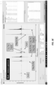
- FIGS. 3A and 3B shows a hyphenated GC-MRR instrument 300 that can analyze difficult and/or complex mixtures in a single run. It can perform compound-specific isotope analyses (CSIA), including isotopic fractionation analysis and quantification, that cannot be done via any other method. For example, it can identify, without a reference, isomers and other compounds that cannot be separated using GC alone.
- CSIA compound-specific isotope analyses
- the GC-MRR instrument 300 includes a gas chromatograph 310 coupled to an MRR spectrometer 320 with a temperature-regulated flow interface 330.
- the gas chromatograph 310 has a carrier gas source 312 that flows a carrier gas, such as helium, hydrogen, neon, or argon, through a column 314.
- the carrier gas pushes an analyte, which may have many different chemical constituents, including isomers, isotopes, isotopomers, and isotopologues, through the column 314 and into the MRR spectrometer 320 via the flow interface 330.
- This analyte may be (periodically) siphoned off a continuous stream or flow of gas or liquid, accumulated and volatilized, if appropriate, and injected into the column 314 such that the gas chromatograph effectively samples the continuous flow, much like an analog-to-digital converter (ADC) samples an analog signal.
- ADC analog-to-digital converter
- analyte's constituents propagate through the column 314 at different rates and so may appear at the end of the column 314 at different points in time. If these points in time are separated widely enough, the constituents can be resolved at the output of the column 314.
- the carrier gas pushes the (at least partially separated) components through the interface 330 and into the MRR spectrometer's measurement chamber 324 so that the MRR spectrometer 320 can measure the components' MRR spectra.
- This interface 330 makes it possible to inject samples either through the GC column 314 or directly into the MRR spectrometer 320 (e.g., for pure compounds or simple mixtures where GC separation is not necessary). In other words, some samples may require GC separation whereas others may not. Samples that do not require GC separation can be injected samples directly into the MRR spectrometer (not through the GC) while other samples could be injected through the GC.
- the measurement chamber 324 may be a flow cell with at least one pair of holes that allow the gas-phase components and the carrier gas to enter and exit.
- a pulsed-jet expansion nozzle, a continuous-wave jet, or a buffer gas cooling cell may introduce the components into the measurement chamber 324 while simultaneously rotationally cooling them for better measurement performance as described below in greater detail.
- the MRR spectrometer 320 measures the MRR spectrum of each component by subjecting the component to one or more excitation pulses of microwave and/or millimeter-wave radiation.
- This excitation pulse is generated by a signal generator 321, such as an arbitrary waveform generator, direct digital synthesizer, or pulse pattern generator, and may be filtered, frequency-multiplied, and/or up-converted with optional circuitry 322.
- a source 323 applies the excitation pulse to the molecules in the measurement chamber 324.
- the interface 330 can also be coupled to (in fluid communication with) a second carrier gas source 352.
- the second carrier gas source 352 flows a second carrier gas to the interface 330 for pushing or propelling the analyte components into the MRR spectrometer's measurement chamber 324.
- the first and second carrier gases can be different-for example, the first carrier gas may be helium or hydrogen, and the second carrier gas may be neon or argon as described in greater detail below.
- the interface 330 can also be coupled to (in fluid communication with) and a (chiral) tag source 354.
- Mixing chiral tags from the chiral tag source 354 with the analyte components in a reservoir in the interface 330 causes the chiral tags to attach themselves to the different components.
- the chiral tags change the moments of inertia of different enantiomers among the analyte components, making it possible to resolve and quantify the enantiomers from their MRR spectra as described below.
- the tag source 354 may store and supply other types of tags, including polar molecules for tagging a nonpolar molecule, which has no MRR spectrum, to produce a complex that has a dipole moment and therefore can be detected by MRR.
- the excited molecules emit coherent radiation in response to the excitation at their characteristic rotational frequencies via free induction decay (FID) for several microseconds.
- a receiver 326 detects the analog FID signal, which is digitized by an ADC 327.
- a processor 340 e.g., a Field Programmable Gate Array (FPGA)
- FPGA Field Programmable Gate Array
- the processor 340 can identify and automatically quantify individual components of the analyte based on the MRR spectra. Unassigned peaks in the MRR spectra can be further analyzed for characterization using theoretical predictions of relevant species.
- the processor 340 may continuously measure and record the MRR spectra of eluates as they exit the GC column 314. In some cases, the processor 340 records and processes all of the MRR spectra. In other cases, the processor 340 records all of the time-domain data and Fourier-transforms only those segments corresponding to "interesting" outputs from the GC column 314 in order to conserve processing resources and reduce total processing time. The processor 340 may discard unprocessed or unexamined time-domain and/or Fourier-domain data.
- an auxiliary (universal) detector 350 may trigger an MRR measurement based on the output of the GC column 314.
- This auxiliary detector 350 can either be in-line (sample the same gas stream), as shown in FIG. 3A , or split (such as an FID or MS detector where the analytes are destroyed).
- the auxiliary detector 350 detects a peak in the GC output, it sends a trigger signal to the processor 340, which in turn triggers emission of the excitation pulse(s) by the signal generator 321 and measures and analyzes the resulting FID signals.
- the processor 340 may also record all of the MRR data, as explained above, and discard MRR data that does not map to a chromatographic peak sensed by the auxiliary detector 350.
- the auxiliary detector data can be combined with the MRR data to provide a more complete analysis of the analyte, e.g., the auxiliary detector may sense components without a dipole moment while isotopic information from the MRR spectrometer 320 can complete characterization of other components.
- FIG. 3B is a photograph of a sample instantiation of the measurement chamber 324 and MRR spectrometer 320 in the GC-MRR spectroscopy system 320.
- This MRR spectrometer 320 is pictured as a microwave MRR spectrometer configured to make targeted measurements.
- a sample inlet 332 is on the left side of the measurement chamber 324.
- Two spherical mirrors 328 are on the left and right ports - a supersonic expansion nozzle 334 is mounted into one port, while the other is held onto the vacuum on an automatically controlled translation stage 344, which is controlled by the processor 340.
- the mirrors 328 make the measurement cavity 324 into a resonant Fabry-Perot cavity.
- the translation stage 344 tunes the length of the resonant cavity (and hence the cavity's resonant frequencies) in order to allow the measurement of targeted resonances of interest. Measuring targeted resonances increases measurement sensitivity.
- microwave horns (not shown) are used instead of the mirrors 328. These horns can be mounted orthogonal to the targeted mirrors 328. One horn can be attached to the flange 329 closest to the reader in FIG. 6 , while the other can be attached on the opposite side (not shown).
- the measurement parameters, including the translation stage and excitation frequency settings, and measurement results can be shown via a display 342 that is operably coupled to the processor 340 ( FIG. 3A ).
- FIGS. 3C and 3D illustrate two views of a user interface that can be shown on the display 342.
- the view shown in FIG. 3C shows the interface displaying a broadband, millimeter-wave MRR spectrum of a mixture of eight isotopologues of acetonitrile (CH 3 CN). Because of their similar structures, only one of the eight isotopologues (CD 3 CN) could be separated from the others using GC. The remaining seven species come off the GC column at the same time (i.e., the other seven species are co-eluted) and are impossible to resolve using GC alone.
- CH 3 CN acetonitrile
- the upper limit on molecular weight of the analyte may be about 150 amu, and the sensitivity at molecular weights of 100-150 amu may be limited because MRR spectra of roomtemperature molecules tend to become extremely weak above 150 amu.
- using a pulsed-jet supersonic expansion source, continuous-wave jet, or a buffer gas cooling cell rotationally cools molecules for MRR analysis while also keeping them in the gas phase.
- a GC-MRR instrument with a pulsed-jet expansion source, continuous-wave jet, or buffer gas cooling cell can analyze molecules with higher molecular weights (e.g., up to 400 amu or higher) thanks to this rotational cooling.
- FIG. 4 shows an expanded view of a pulsed-jet supersonic nozzle 400 suitable for injecting analyte into the measurement chamber of an MRR spectrometer in a GC-MRR system such as the one shown in FIGS. 3A and 3B .
- a GC flow inlet 410 for analyte components from the GC column
- a vent valve inlet 430 for quickly getting rid of solvents or other volatile matrix components
- an optional inlet 430 for (additional) carrier gas.
- the GC flow inlet 410 and vent valve inlet 420 can be made of 1/16" tubing and can be heated to at least 300 °C to allow for direct inlet of the GC column at temperature.
- the central 6.35 mm (1/4") gas connection 430 for the carrier gas is optional and can be used for a purge gas to clean samples quickly. All three gas flows combine in a reservoir 440, which can have a volume of about 500 ⁇ L or less. Reducing the reservoir volume can reduce extra-column broadening.
- Injecting neon carrier gas at the nozzle may enhance pulsed valve operation. If neon carrier gas is injected at the nozzle, then the GC column can operate with a different carrier gas, such as hydrogen or helium, since the neon would dominate the rotational cooling caused by the supersonic pulsed injection of the analyte component(s) into the microwave MRR measurement chamber. Both carrier gases can be injected into the MRR measurement chamber.
- a different carrier gas such as hydrogen or helium
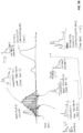
- FIGS. 5A and 5B show simulated MRR spectra of isopulegol (a monoterpene and menthol intermediate, mass 154 amu) at four molecular temperatures: room temperature (300 K; bottom), 100 K (lower middle), 20 K (upper middle), and 2 K (top).
- FIG. 5A shows the spectra over microwave and millimeter-wave frequencies of 0 to 600 GHz
- FIG. 5B shows the spectra in the microwave band of 0 to 18 GHz.
- These spectra show improved measurement performance at lower temperatures, which can be achieved by using a pulsed-jet supersonic expansion source to inject the GC output into the vacuum chamber of the MRR spectrometer in a GC-MRR spectroscopy system.
- 5A and 5B is due to a smaller number of rovibrational states being populated.
- the MRR spectra shift to lower frequency.
- the shift of spectra to lower frequency is also advantageous, because it is possible to achieve higher excitation power levels with less expensive components in the microwave region (particularly below 18 GHz, e.g., from 6-18 GHz) than in the millimeter-wave region (e.g., 75 GHz and higher). Nearly every molecule heavier than 50 amu has a spectral intensity peak in microwave range (6-18 GHz).
- FIG. 7A illustrates a method 700 for processing the raw data measured by an integrated GC-MRR instrument 300 shown in FIG. 3A (this method 700 can also be used to analyze LC-MRR data).
- the GC-MRR instrument 300 obtains time-domain data (702) by injected the (at least partially) separated components from the GC column 314 into the MRR spectrometer's measurement chamber 324, then exciting the component(s) in the measurement chamber 324 with a microwave or millimeter-wave pulse and recording the resulting time-domain free induction decay (FID) signal(s). Over time, the instrument 300 records a series of these time-domain FID traces, e.g., at a rate of 5 Hz or 10 Hz.
- time-domain FID traces e.g., at a rate of 5 Hz or 10 Hz.
- FIGS. 7C and 7D show a single GC-MRR analysis of 24 isotopic species of five common organic molecules that demonstrates the feasibility and utility of the GC-MRR instrument obtained using the process of FIG. 7A .
- FIG. 7C shows a TMC, where the peak intensities of the observed transitions are summed.
- the TMC indicates five dominant peaks and two small shoulders just prior to the main acetone and acetonitrile peaks (at 3.2 minutes and 7.6 minutes, respectively). These small, partially resolved shoulders are fully deuterated acetone (Acetone-d6) and triply deuterated acetonitrile (ACN-d3), which are chromatographically separated from their related isotopologues and isotopomers.
- Each point in the TMC includes a broadband MRR spectrum allowing the individual contributions of the different species to be separated.
- the extraordinary selectivity of MRR spectroscopy allows resolution of the TMC into 24 EMCs, shown in FIG. 7D , with one EMC for each isotopically distinct compound.
- the transition intensities only at the frequencies of that isotopic species are summed. Isotope pattern matching/analysis is not needed for molecular identification, as the isotopes can be determined directly on their moments of inertia.
- Molecules that have identical masses can be distinguished and identified from the MRR spectra due to their different moments of inertia.
- FIG. 8A shows the TMC, obtained by GC-MRR spectroscopy and the process in FIG. 7A , for bromoethane and five heterocyclic compounds.
- FIG. 8B shows isotopologue-specific EMCs showing the natural isotopic abundances for bromoethane and 2-chloropyridine. Integration of GC-MRR peak areas provide quantitative information for all species. While not used in the TMC of FIG. 8A or EMCs of FIG. 8B , changes in dipole moments and rotational constants are typically small. The ratio between MRR peak intensities also can be used directly as an accurate determination of isotopic ratios.
- isobaric compounds pose no problems. Further, peak (compound) coelution does not cause signal suppression or enhancement. This is due, in significant part, to the fact that MRR spectral detection is very high resolution and provides an abundance of lines highly specific to one compound even if that compound is an isomer or an isotopologue or isotopomer of another. Additionally, there are no suppression effects such as those that exist in mass spectrometry.
- isotope composition is used for evaluating biotic and abiotic reactions of organic feed/contaminants in ground and natural aquatic systems.
- compound-specific isotope analysis (CSIA) and position-specific isotope analysis (PSIA) offer widely applicable approaches to study the chemical reactions in complex matrices and provide a better understanding of pollutant degradation. This degradation can occur via enzymatic pathways or by photochemical or organic reactions consisting of substitution, elimination, or electron transfer.
- CSIA provides a more in-depth insight into degradation pathways by pinpointing the reactive atoms in a given trace contaminant molecule.
- isotope-ratio mass spectrometry for carbon, hydrogen, and nitrogen but isotope-ratio mass spectrometry measurements for oxygen, sulfur, and chlorine are difficult.
- PSIA examines intra molecular isotopic variations.
- PSIA for carbon
- SNIF-NMR site-specific natural isotope fractionation-nuclear magnetic resonance
- NMR is a time-consuming, low-sensitivity technique.
- significant preconcentration of trace compounds is a requirement before NMR measurements.
- GC-MRR can address these challenging cases of CSIA and PSIA without post-column conversion or purification.
- TABLE 2 shows clearly different kinetics of biodepletion for various isotopologues of acetonitrile by two different bacteria.
- the data shows different kinetics of biodepletion for various isotopic isotopologues of acetonitrile by two different bacteria.
- the normal species of acetonitrile is depleted at the fastest rate by E. coli, with no detectable differentiation between three singly substituted isotopologues.
- Even more interesting is the fact that for V. fischeri, the CH 3 13 CN isotopologue is selectively depleted. No other analytical method or combination of methods could so easily characterize these phenomena.
- FIG. 9 shows a liquid chromatography (LC)-MRR spectroscopy system 900 with a liquid chromatograph 910 coupled to an MRR spectrometer 920, such as a microwave or millimeter-wave MRR spectrometer configured for broadband and/or targeted measurements.
- the liquid chromatograph 910 includes a column 914 that receives a liquid analyte via an inlet 916, e.g., for example from a continuously flowing sample source.
- a solvent flowing from a solvent source 912 pushes the liquid analyte through the column 914, where the analyte at least partially separates into its constituent components.
- a volatilization interface 930 couples the at least partially separated analyte components into the MRR spectrometer 920. It volatilizes the analyte components-for example, it may heat them until they evaporate.
- Carrier gas such as neon or helium
- a carrier gas source 934 pushes the volatilized analyte through the volatilization interface 930 and to a pulsed-jet supersonic nozzle 932 coupled to the volatilization interface 930.
- the nozzle 932 injects the volatilized analyte component(s) into the MRR spectrometer's measurement chamber 924, which is pumped down to vacuum pressure (e.g., 10 -6 torr) by a vacuum pump 925.
- a microwave source like the one in FIG. 3A illuminates the analyte component(s) in the measurement chamber with one or more targeted or broadband excitation pulses.
- a receiver like the one in FIG. 3A detects the FID signals emitted by the volatilized analyte component(s) in response to the excitation pulse(s).
- Electronics detect and process the FID signals to produce MRR spectra.
- the MRR spectra can be measured continuously or on-demand, e.g., in response to detection of peaks in the LC column output sensed by an auxiliary detector.
- Chiral analysis is an area where GC-MRR can have significant added value, particularly using a gas-phase complexation technique called chiral tagging to convert enantiomers into diastereomers in MRR for chiral analysis.
- chiral tagging a gas-phase complexation technique
- a small number of small, volatile, chiral molecules have been shown to efficiently complex with a wide range of chemical analytes and allow for precise enantiomeric excess determinations of these compounds within mixtures.
- chiral tagging see, e.g., U.S. Pre-Grant Publication No. 2019/0302015 , entitled "Cavity-Enhanced Fourier Transform Spectroscopy for Chiral Analysis”.
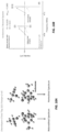
- FIGS. 10A and 10B show the idea behind chiral tagging.
- chiral tagging involves "tagging" analytes with a small, chiral molecule of known stereochemistry, such as the verbenone/butynol system in FIG. 10A .
- Weakly bound complexes, stabilized through a combination of hydrogen bonding, van der Waals, and other forces, can be formed efficiently in pulsed supersonic expansion nozzles.
- the resulting diastereomeric complexes have distinct moments of inertia and can be resolved through the power of MRR spectroscopy as described above and shown in FIG. 10B .
- Chiral analysis is important in a wide range of applications, including pharmaceuticals, environmental analysis, and metabolite analysis.
- FIG. 10A shows that enantiomers of verbenone (an example chiral molecule) have identical MRR spectra as they have the same moments of inertia.
- a chiral tag in this case, (S)-3-butyn-2-ol
- a difference in moment of inertia results, which produces two species with different moments of inertia and so distinct MRR spectra.
- the two complexes are referred to as heterochiral (i.e., (R,R)-verbenone + (S)-3-butyn-2-ol) or homochiral (i.e., (S,S)-verbenone + (S)-3-butyn-2-ol).
- Chiral monitoring can be integrated into an GC-MRR instrument with an accessory system for introducing a gas phase chiral tag by an additional valve at the interface of the GC outlet, prior to the pulsed jet sampling source.
- the tag can be mixed in with the eluting sample post-column.
- the spectral library may include entries for reference chiral molecules (the chiral tags). This chiral MRR method can be utilized instead of, or in conjunction with, chiral GC separation, opening up a range of new separation and identification capabilities.
- inventive concepts may be embodied as one or more methods, of which an example has been provided.
- the acts performed as part of the method may be ordered in any suitable way. Accordingly, embodiments may be constructed in which acts are performed in an order different than illustrated, which may include performing some acts simultaneously, even though shown as sequential acts in illustrative embodiments.
- a reference to "A and/or B", when used in conjunction with open-ended language such as “comprising” can refer, in one embodiment, to A only (optionally including elements other than B); in another embodiment, to B only (optionally including elements other than A); in yet another embodiment, to both A and B (optionally including other elements); etc.
- the phrase "at least one,” in reference to a list of one or more elements, should be understood to mean at least one element selected from any one or more of the elements in the list of elements, but not necessarily including at least one of each and every element specifically listed within the list of elements and not excluding any combinations of elements in the list of elements.
- This definition also allows that elements may optionally be present other than the elements specifically identified within the list of elements to which the phrase "at least one" refers, whether related or unrelated to those elements specifically identified.
- At least one of A and B can refer, in one embodiment, to at least one, optionally including more than one, A, with no B present (and optionally including elements other than B); in another embodiment, to at least one, optionally including more than one, B, with no A present (and optionally including elements other than A); in yet another embodiment, to at least one, optionally including more than one, A, and at least one, optionally including more than one, B (and optionally including other elements); etc.
Landscapes
- Physics & Mathematics (AREA)
- Health & Medical Sciences (AREA)
- Life Sciences & Earth Sciences (AREA)
- Chemical & Material Sciences (AREA)
- Analytical Chemistry (AREA)
- Biochemistry (AREA)
- General Health & Medical Sciences (AREA)
- General Physics & Mathematics (AREA)
- Immunology (AREA)
- Pathology (AREA)
- Molecular Biology (AREA)
- Spectroscopy & Molecular Physics (AREA)
- Other Investigation Or Analysis Of Materials By Electrical Means (AREA)
Claims (15)
- System, umfassend:einen Chromatographen (310, 910) zum Auftrennen eines Analyten in Bestandteile, wobei die Bestandteile koeluierende Bestandteile umfassen, die sich mit der Chromatographie nicht trennen lassen;ein Spektrometer für die Rotationsspektroskopie (molecular rotational resonance, MRR) (320) in Fluidverbindung mit dem Chromatographen (310, 910) zum Messen von MRR-Spektren der koeluierenden Bestandteile undeinen Prozessor (340), der funktionsmäßig mit dem MRR-Spektrometer (320) verbunden und so ausgelegt ist, dass zumindest teilweise auf Basis der MRR-Spektren unter den koeluierenden Bestandteilen des Analyten ein Isomer, ein Isotopolog und/oder ein Isotopomer aufgelöst wird.
- System nach Anspruch 1, wobei der Chromatograph (310, 910) ein Gaschromatograph (310) ist, wobei das MRR-Spektrometer (320) ein MRR-Mikrowellenspektrometer mit einer Expansionskammer ist, die einen Resonanzmessraum (324) umfasst, und ferner umfassend:
eine Quelle für Trägergas (934) in Fluidverbindung mit dem Gaschromatographen (310) und dem Resonanzmessraum (324), damit der Analyt durch den Gaschromatographen (310) getrieben wird und die koeluierenden Bestandteile in die Expansionskammer getrieben werden. - System nach Anspruch 1, wobei der Chromatograph (310, 910) ein Gaschromatograph (310) ist und wobei das MRR-Spektrometer (320) optional eine Durchflusszelle (324) zum Aufnehmen der koeluierenden Bestandteile des Analyten aus dem Gaschromatographen (310) umfasst.
- System nach Anspruch 1, wobei der Chromatograph (310, 910) ein Flüssigchromatograph (910) ist, wobei das MRR-Spektrometer (320) ein MRR-Mikrowellenspektrometer mit einer Expansionskammer ist, und ferner umfassend:eine Verflüchtigungsschnittstelle (930) in thermischer Verbindung mit dem Flüssigchromatographen (910) zum Verflüchtigen der Bestandteile, undeine Quelle für Trägergas (934) in Fluidverbindung mit der Verflüchtigungsschnittstelle (930), damit die koeluierenden Bestandteile aus der Verflüchtigungsschnittstelle (930) und in die Expansionskammer getrieben werden.
- System nach Anspruch 1, wobei das MRR-Spektrometer (320) so ausgelegt ist, dass es ein Spektrum mit einer Bandbreite von mindestens 50 MHz von mindestens einem Eluat misst, das aus dem Chromatographen (310, 910) austritt.
- System nach Anspruch 1, wobei der Prozessor (340) so ausgelegt ist, dass zumindest teilweise auf Basis der MRR-Spektren der Bestandteile ein Molekül-Gesamtchromatogramm des Analyten erstellt wird.
- System nach Anspruch 1, das ferner Folgendes umfasst:einen Hilfsdetektor (350), der funktionsmäßig mit dem Chromatographen (310, 910) verbunden ist und so einen Peak in einem Ergebnis des Chromatographen (310, 910) misst, wobei der Prozessor (340) so ausgelegt ist, dass er als Reaktion auf den Peak eine Messung des MRR-Spektrums auslöst und/oder zumindest teilweise auf Basis des Peaks die MRR-Spektren verarbeitet; und/odereine Düse in Fluidverbindung mit dem Chromatographen (310, 910) und dem MRR-Spektrometer (320) zum Senken der Rotationstemperatur von Molekülen von dem mindestens einen der Bestandteile, bevor das MRR-Spektrometer (320) die MRR-Spektren misst.
- Verfahren zum Analysieren eines Analyten, wobei das Verfahren Folgendes umfasst:Auftrennen des Analyten mit einem Chromatographen (310, 910) in Bestandteile, wobei die Bestandteile koeluierende Bestandteile umfassen, die sich mit dem Chromatographen (310, 910) nicht trennen lassen;Messen von MRR-Spektren der koeluierenden Bestandteile mit einem MRR-Spektrometer (320) in Fluidverbindung mit dem Chromatographen (310, 910); undunter den koeluierenden Bestandteilen des Analyten Auflösen, zumindest teilweise auf Basis der MRR-Spektren, eines Isomers, eines Isotopologs und/oder eines Isotopomers.
- Verfahren nach Anspruch 8, wobei das Auftrennen des Analyten in Bestandteile ein Untersuchen eines kontinuierlichen Stroms des Analyten mit dem Chromatographen (310, 910) umfasst und gegebenenfalls ferner Folgendes umfasst:Messen eines Peaks in einem Ergebnis des Chromatographen (310, 910) undals Reaktion auf das Messen des Peaks Auslösen einer Messung des MRR-Spektrums.
- Verfahren nach Anspruch 8, wobei das Messen der MRR-Spektren der koeluierenden Bestandteile ein Messen eines Breitbandspektrums eines Eluats umfasst, das aus dem Chromatographen (310, 910) austritt.
- Verfahren nach Anspruch 8, ferner umfassend:Senken der Rotationstemperatur von Molekülen der koeluierenden Bestandteile vor dem Messen der MRR-Spektren der koeluierenden Bestandteile, undwobei das Messen der MRR-Spektren ein Anregen von dem mindestens einen der Bestandteile mit einem Mikrowellenanregungssignal umfasst.
- Verfahren nach Anspruch 8, ferner umfassend:zumindest teilweise auf Basis der MRR-Spektren Identifizieren von mindestens einem unbekannten Bestandteil des Analyten; und/oderzumindest teilweise auf Basis der MRR-Spektren Quantifizieren von dem mindestens einen der Bestandteile; und/oderzumindest teilweise auf Basis der MRR-Spektren Erstellen eines Molekül-Gesamtchromatogramms des Analyten.
- Verfahren nach Anspruch 8, wobei der Chromatograph (310, 910) ein Gaschromatograph (310) ist, das MRR-Spektrometer (320) ein MRR-Spektrometer mit einer Expansionskammer ist, und ferner umfassend:
mit einem Trägergas Treiben des Analyten durch den Gaschromatographen (310, 910) und des mindestens einen der Bestandteile in die Expansionskammer. - Verfahren nach Anspruch 8, wobei der Chromatograph (310, 910) ein Flüssigchromatograph (910) ist, das MRR-Spektrometer (320) ein MRR-Mikrowellenspektrometer (320) mit einer Expansionskammer ist, und ferner umfassend:Verflüchtigen von dem mindestens einen der Bestandteile, undmit einem Trägergas Treiben von dem mindestens einen der Bestandteile aus der Verflüchtigungsschnittstelle (930) und in die Expansionskammer.
- Verfahren nach Anspruch 8, ferner umfassend:Anbringen eines chiralen Markers an dem mindestens einen der Bestandteile vor dem Messen der MRR-Spektren, undauf Basis des MRR-Spektrums Identifizieren eines Enantiomers unter den Bestandteilen des Analyten und/oder auf Basis der MRR-Spektren Bestimmen eines Enantiomerüberschusses der Bestandteile des Analyten.
Applications Claiming Priority (4)
| Application Number | Priority Date | Filing Date | Title |
|---|---|---|---|
| US201962844280P | 2019-05-07 | 2019-05-07 | |
| US201962913082P | 2019-10-09 | 2019-10-09 | |
| US202062977846P | 2020-02-18 | 2020-02-18 | |
| PCT/US2020/031890 WO2020227541A1 (en) | 2019-05-07 | 2020-05-07 | Highly selective chromatography-molecular rotational resonance spectroscopy systems and methods |
Publications (4)
| Publication Number | Publication Date |
|---|---|
| EP3966537A1 EP3966537A1 (de) | 2022-03-16 |
| EP3966537A4 EP3966537A4 (de) | 2023-01-11 |
| EP3966537C0 EP3966537C0 (de) | 2025-06-25 |
| EP3966537B1 true EP3966537B1 (de) | 2025-06-25 |
Family
ID=73051712
Family Applications (1)
| Application Number | Title | Priority Date | Filing Date |
|---|---|---|---|
| EP20803051.0A Active EP3966537B1 (de) | 2019-05-07 | 2020-05-07 | Hochselektive chromatographie-molekular-rotationsresonanz-spektroskopiesysteme und verfahren |
Country Status (6)
| Country | Link |
|---|---|
| US (1) | US12292399B2 (de) |
| EP (1) | EP3966537B1 (de) |
| JP (1) | JP7651476B2 (de) |
| CN (1) | CN114450566B (de) |
| ES (1) | ES3041535T3 (de) |
| WO (1) | WO2020227541A1 (de) |
Families Citing this family (5)
| Publication number | Priority date | Publication date | Assignee | Title |
|---|---|---|---|---|
| JP7693382B2 (ja) * | 2021-04-30 | 2025-06-17 | テスラ ダイナミック コイルズ ベーフェー | Mri装置 |
| EP4348243A4 (de) * | 2021-05-21 | 2025-04-23 | Brightspec, Inc. | Probennahme für molekulare rotationsresonanzspektroskopie |
| CN115309402B (zh) * | 2022-07-13 | 2023-10-24 | 国网江苏省电力有限公司信息通信分公司 | 一种可量化差异的异构执行程序集合构成方法及装置 |
| CN120917306A (zh) * | 2023-02-21 | 2025-11-07 | 布赖特斯佩克股份有限公司 | 用于同步测量的分子旋转共振光谱仪和其使用方法 |
| WO2025212634A1 (en) * | 2024-04-01 | 2025-10-09 | Brightspec, Inc. | Pulsed valve for molecular resonance rotational (mrr) spectroscopy |
Family Cites Families (25)
| Publication number | Priority date | Publication date | Assignee | Title |
|---|---|---|---|---|
| US3662133A (en) * | 1969-02-18 | 1972-05-09 | Westinghouse Electric Corp | Space-plate arc-chute for an air-break circuit breaker |
| JPS6033039A (ja) * | 1983-08-02 | 1985-02-20 | Sagami Chem Res Center | マイクロ波吸収方式ガス検出装置を用いた安定同位体の連続測定方法 |
| US4607521A (en) * | 1984-11-20 | 1986-08-26 | Sagami Chemical Research Center | Method of improving response characteristics of gas sensor using microwave spectrometer |
| JP2977571B2 (ja) * | 1988-02-26 | 1999-11-15 | モナシュ ユニヴァーシティ | マイクロ波スペクトロメータ |
| DE3929079A1 (de) | 1989-09-01 | 1991-03-21 | Dreizler Helmut | Verfahren und vorrichtung zur analyse gasfoermiger medien mittels mikrowellen |
| US5281256A (en) * | 1990-09-28 | 1994-01-25 | Regents Of The University Of Michigan | Gas chromatography system with column bifurcation and tunable selectivity |
| JP2905614B2 (ja) * | 1991-04-15 | 1999-06-14 | 株式会社トクヤマ | クロマトグラフィー用固定相 |
| US5457316A (en) * | 1994-12-23 | 1995-10-10 | Pcp, Inc. | Method and apparatus for the detection and identification of trace gases |
| RU18173U1 (ru) | 2000-12-21 | 2001-05-27 | Общество с ограниченной ответственностью "Оренбурггазпром" Открытого акционерного общества "Газпром" | Установка разделения бутановой фракции |
| CA2461587C (en) * | 2001-09-27 | 2011-04-26 | Purdue Research Foundation | Materials and methods for controlling isotope effects during fractionation of analytes |
| JP2008515232A (ja) * | 2004-09-30 | 2008-05-08 | アドバンスト・マイクロ・ディバイシズ・インコーポレイテッド | リソグラフィ露光装置における汚染検出および監視のための方法およびシステム、ならびに調整された雰囲気条件下でのその動作方法 |
| DE102004047677B4 (de) | 2004-09-30 | 2007-06-21 | Advanced Micro Devices, Inc., Sunnyvale | Verfahren und System für die Kontaminationserkennung und Überwachung in einer Lithographiebelichtungsanlage und Verfahren zum Betreiben der gleichen unter gesteuerten atomsphärischen Bedingungen |
| WO2011130215A1 (en) | 2010-04-12 | 2011-10-20 | President And Fellows Of Harvard College | Gas phase cooling and mixture analysis |
| WO2011160013A1 (en) | 2010-06-17 | 2011-12-22 | Brooks Hart Pate | Chirped pulse frequency-domain comb for spectroscopy |
| US8873043B2 (en) | 2011-03-18 | 2014-10-28 | University Of Virginia Patent Foundation | Segmented chirped-pulse fourier transform spectroscopy |
| CN104169689B (zh) | 2012-03-07 | 2017-07-18 | Skf公司 | 传感器单元以及包括此传感器单元的轴承组件 |
| WO2013154732A1 (en) * | 2012-04-11 | 2013-10-17 | President And Fellows Of Harvard College | Buffer gas cooling and mixture analysis |
| US9116158B2 (en) | 2012-10-18 | 2015-08-25 | Vuv Analytics, Inc. | Vacuum ultraviolet absorption spectroscopy system and method |
| AU2014278150B2 (en) * | 2013-06-14 | 2018-08-30 | University Of Virginia Patent Foundation | Apparatus and techniques for Fourier transform millimeter-wave spectroscopy |
| EP3158303B1 (de) | 2014-06-17 | 2021-05-26 | University Of Virginia Patent Foundation | Fouriertransformationsspektroskopie mit frequenzsprungspreizspektrum (fhss) |
| CN107709983B (zh) * | 2015-06-10 | 2020-05-22 | 真空紫外线分析学股份有限公司 | 使用真空紫外光谱和气相色谱对复杂样品进行详细的批量分类分析的方法 |
| CN108700459B (zh) | 2016-01-07 | 2021-05-25 | 布赖特斯佩克股份有限公司 | 用于直接倍增傅立叶变换毫米波光谱的方法和装置 |
| US11237104B2 (en) * | 2016-10-26 | 2022-02-01 | University Of Virginia Patent Foundation | Cavity-enhanced fourier transform spectroscopy for chiral analysis |
| RU181173U1 (ru) * | 2018-02-20 | 2018-07-05 | федеральное государственное бюджетное образовательное учреждение высшего образования "МИРЭА-Российский технологический университет" | Устройство для электронографического и микроволнового исследования компонент вещества, разделённого хроматографом |
| EP3833244B1 (de) * | 2018-08-08 | 2026-02-25 | Brightspec, Inc. | Verfahren und vorrichtung zur erfassung von proben mit geringer volatilität |
-
2020
- 2020-05-07 CN CN202080049524.3A patent/CN114450566B/zh active Active
- 2020-05-07 ES ES20803051T patent/ES3041535T3/es active Active
- 2020-05-07 WO PCT/US2020/031890 patent/WO2020227541A1/en not_active Ceased
- 2020-05-07 JP JP2021566096A patent/JP7651476B2/ja active Active
- 2020-05-07 US US17/609,246 patent/US12292399B2/en active Active
- 2020-05-07 EP EP20803051.0A patent/EP3966537B1/de active Active
Also Published As
| Publication number | Publication date |
|---|---|
| US12292399B2 (en) | 2025-05-06 |
| CN114450566B (zh) | 2025-05-02 |
| US20220196582A1 (en) | 2022-06-23 |
| CN114450566A (zh) | 2022-05-06 |
| EP3966537C0 (de) | 2025-06-25 |
| EP3966537A4 (de) | 2023-01-11 |
| ES3041535T3 (en) | 2025-11-12 |
| EP3966537A1 (de) | 2022-03-16 |
| WO2020227541A1 (en) | 2020-11-12 |
| JP2022531888A (ja) | 2022-07-12 |
| JP7651476B2 (ja) | 2025-03-26 |
Similar Documents
| Publication | Publication Date | Title |
|---|---|---|
| EP3966537B1 (de) | Hochselektive chromatographie-molekular-rotationsresonanz-spektroskopiesysteme und verfahren | |
| Zoccali et al. | Fast gas chromatography-mass spectrometry: A review of the last decade | |
| Hayen et al. | Dielectric barrier discharge ionization for liquid chromatography/mass spectrometry | |
| Smoluch et al. | Plasma‐based ambient ionization mass spectrometry in bioanalytical sciences | |
| AU2003218649B2 (en) | Mass spectrometry method for analysing mixtures of substances | |
| Stahnke et al. | The influence of electrospray ion source design on matrix effects | |
| Locatelli et al. | Recent HPLC strategies to improve sensitivity and selectivity for the analysis of complex matrices | |
| Zhang et al. | Recent advances in mass spectrometry techniques for atmospheric chemistry research on molecular‐level | |
| Seemann et al. | Electron ionization LC‐MS with supersonic molecular beams—the new concept, benefits and applications | |
| Awuchi et al. | Hyphenated techniques | |
| Law et al. | Factors to consider in the development of generic bioanalytical high-performance liquid chromatographic–mass spectrometric methods to support drug discovery | |
| Guzowski et al. | Gas sampling glow discharge: a versatile ionization source for gas chromatography time-of-flight mass spectrometry | |
| Neill et al. | Analysis of isomeric mixtures by molecular rotational resonance spectroscopy | |
| Levsen et al. | Application of high-performance liquid chromatography coupled to nuclear magnetic resonance and high-performance liquid chromatography coupled to mass spectrometry to complex environmental samples | |
| Van den Bergh et al. | Identification of the oxidation products of the reaction between α-pinene and hydroxyl radicals by gas and high-performance liquid chromatography with mass spectrometric detection | |
| Cho et al. | Evaluation of direct analysis in real time mass spectrometry for onsite monitoring of batch slurry reactions | |
| Blanazs et al. | Coupling and optimisation of online nuclear magnetic resonance spectroscopy and mass spectrometry for process monitoring to cover the broad range of process concentration | |
| Thoben et al. | How to Improve the Resolving Power of Compact Electrospray Ionization Ion Mobility Spectrometers | |
| Guzowski Jr et al. | Electrothermal vaporization for sample introduction into a gas sampling glow discharge time-of-flight mass spectrometer | |
| Fay et al. | Novel mass spectrometry methods in flavour analysis | |
| Gross | Hyphenated Methods | |
| García-Reyes et al. | The potential of ambient desorption ionization methods combined with high-resolution mass spectrometry for pesticide testing in food | |
| Thombare et al. | REVIEW ON HYPHENATED TECHNIQUE | |
| Schmitz et al. | Identification and quantitation in liquid chromatography–mass spectrometry | |
| Gross | Practical aspects of electron ionization |
Legal Events
| Date | Code | Title | Description |
|---|---|---|---|
| STAA | Information on the status of an ep patent application or granted ep patent |
Free format text: STATUS: THE INTERNATIONAL PUBLICATION HAS BEEN MADE |
|
| PUAI | Public reference made under article 153(3) epc to a published international application that has entered the european phase |
Free format text: ORIGINAL CODE: 0009012 |
|
| STAA | Information on the status of an ep patent application or granted ep patent |
Free format text: STATUS: REQUEST FOR EXAMINATION WAS MADE |
|
| 17P | Request for examination filed |
Effective date: 20211202 |
|
| AK | Designated contracting states |
Kind code of ref document: A1 Designated state(s): AL AT BE BG CH CY CZ DE DK EE ES FI FR GB GR HR HU IE IS IT LI LT LU LV MC MK MT NL NO PL PT RO RS SE SI SK SM TR |
|
| DAV | Request for validation of the european patent (deleted) | ||
| DAX | Request for extension of the european patent (deleted) | ||
| REG | Reference to a national code |
Ref country code: DE Ref legal event code: R079 Free format text: PREVIOUS MAIN CLASS: G01J0003280000 Ipc: G01N0030620000 Ref document number: 602020053403 Country of ref document: DE |
|
| A4 | Supplementary search report drawn up and despatched |
Effective date: 20221212 |
|
| RIC1 | Information provided on ipc code assigned before grant |
Ipc: G01N 30/88 20060101ALN20221207BHEP Ipc: G01N 30/62 20060101AFI20221207BHEP |
|
| P01 | Opt-out of the competence of the unified patent court (upc) registered |
Effective date: 20230524 |
|
| GRAP | Despatch of communication of intention to grant a patent |
Free format text: ORIGINAL CODE: EPIDOSNIGR1 |
|
| STAA | Information on the status of an ep patent application or granted ep patent |
Free format text: STATUS: GRANT OF PATENT IS INTENDED |
|
| RIC1 | Information provided on ipc code assigned before grant |
Ipc: G01N 22/00 20060101ALN20250114BHEP Ipc: G01N 30/88 20060101ALN20250114BHEP Ipc: G01N 30/62 20060101AFI20250114BHEP |
|
| INTG | Intention to grant announced |
Effective date: 20250127 |
|
| GRAS | Grant fee paid |
Free format text: ORIGINAL CODE: EPIDOSNIGR3 |
|
| GRAA | (expected) grant |
Free format text: ORIGINAL CODE: 0009210 |
|
| STAA | Information on the status of an ep patent application or granted ep patent |
Free format text: STATUS: THE PATENT HAS BEEN GRANTED |
|
| AK | Designated contracting states |
Kind code of ref document: B1 Designated state(s): AL AT BE BG CH CY CZ DE DK EE ES FI FR GB GR HR HU IE IS IT LI LT LU LV MC MK MT NL NO PL PT RO RS SE SI SK SM TR |
|
| REG | Reference to a national code |
Ref country code: GB Ref legal event code: FG4D |
|
| REG | Reference to a national code |
Ref country code: CH Ref legal event code: EP |
|
| REG | Reference to a national code |
Ref country code: DE Ref legal event code: R096 Ref document number: 602020053403 Country of ref document: DE |
|
| REG | Reference to a national code |
Ref country code: CH Ref legal event code: EP |
|
| REG | Reference to a national code |
Ref country code: IE Ref legal event code: FG4D |
|
| U01 | Request for unitary effect filed |
Effective date: 20250723 |
|
| U07 | Unitary effect registered |
Designated state(s): AT BE BG DE DK EE FI FR IT LT LU LV MT NL PT RO SE SI Effective date: 20250812 |
|
| P04 | Withdrawal of opt-out of the competence of the unified patent court (upc) registered |
Free format text: CASE NUMBER: UPC_APP_292243_1/2023 Effective date: 20250812 |
|
| PG25 | Lapsed in a contracting state [announced via postgrant information from national office to epo] |
Ref country code: GR Free format text: LAPSE BECAUSE OF FAILURE TO SUBMIT A TRANSLATION OF THE DESCRIPTION OR TO PAY THE FEE WITHIN THE PRESCRIBED TIME-LIMIT Effective date: 20250926 Ref country code: NO Free format text: LAPSE BECAUSE OF FAILURE TO SUBMIT A TRANSLATION OF THE DESCRIPTION OR TO PAY THE FEE WITHIN THE PRESCRIBED TIME-LIMIT Effective date: 20250925 |
|
| PG25 | Lapsed in a contracting state [announced via postgrant information from national office to epo] |
Ref country code: HR Free format text: LAPSE BECAUSE OF FAILURE TO SUBMIT A TRANSLATION OF THE DESCRIPTION OR TO PAY THE FEE WITHIN THE PRESCRIBED TIME-LIMIT Effective date: 20250625 |
|
| PG25 | Lapsed in a contracting state [announced via postgrant information from national office to epo] |
Ref country code: RS Free format text: LAPSE BECAUSE OF FAILURE TO SUBMIT A TRANSLATION OF THE DESCRIPTION OR TO PAY THE FEE WITHIN THE PRESCRIBED TIME-LIMIT Effective date: 20250925 |
|
| REG | Reference to a national code |
Ref country code: ES Ref legal event code: FG2A Ref document number: 3041535 Country of ref document: ES Kind code of ref document: T3 Effective date: 20251112 |
|
| PG25 | Lapsed in a contracting state [announced via postgrant information from national office to epo] |
Ref country code: IS Free format text: LAPSE BECAUSE OF FAILURE TO SUBMIT A TRANSLATION OF THE DESCRIPTION OR TO PAY THE FEE WITHIN THE PRESCRIBED TIME-LIMIT Effective date: 20251025 |
|
| PG25 | Lapsed in a contracting state [announced via postgrant information from national office to epo] |
Ref country code: SM Free format text: LAPSE BECAUSE OF FAILURE TO SUBMIT A TRANSLATION OF THE DESCRIPTION OR TO PAY THE FEE WITHIN THE PRESCRIBED TIME-LIMIT Effective date: 20250625 |
|
| PG25 | Lapsed in a contracting state [announced via postgrant information from national office to epo] |
Ref country code: CZ Free format text: LAPSE BECAUSE OF FAILURE TO SUBMIT A TRANSLATION OF THE DESCRIPTION OR TO PAY THE FEE WITHIN THE PRESCRIBED TIME-LIMIT Effective date: 20250625 |
|
| PG25 | Lapsed in a contracting state [announced via postgrant information from national office to epo] |
Ref country code: PL Free format text: LAPSE BECAUSE OF FAILURE TO SUBMIT A TRANSLATION OF THE DESCRIPTION OR TO PAY THE FEE WITHIN THE PRESCRIBED TIME-LIMIT Effective date: 20250625 |
|
| PG25 | Lapsed in a contracting state [announced via postgrant information from national office to epo] |
Ref country code: SK Free format text: LAPSE BECAUSE OF FAILURE TO SUBMIT A TRANSLATION OF THE DESCRIPTION OR TO PAY THE FEE WITHIN THE PRESCRIBED TIME-LIMIT Effective date: 20250625 |