EP3965656B1 - Implantierbare vorrichtung zur erfassung von biologischen signalen - Google Patents
Implantierbare vorrichtung zur erfassung von biologischen signalen Download PDFInfo
- Publication number
- EP3965656B1 EP3965656B1 EP20802889.4A EP20802889A EP3965656B1 EP 3965656 B1 EP3965656 B1 EP 3965656B1 EP 20802889 A EP20802889 A EP 20802889A EP 3965656 B1 EP3965656 B1 EP 3965656B1
- Authority
- EP
- European Patent Office
- Prior art keywords
- light
- excitation
- chamber
- signal
- host organism
- Prior art date
- Legal status (The legal status is an assumption and is not a legal conclusion. Google has not performed a legal analysis and makes no representation as to the accuracy of the status listed.)
- Active
Links
Images





Classifications
-
- A—HUMAN NECESSITIES
- A61—MEDICAL OR VETERINARY SCIENCE; HYGIENE
- A61B—DIAGNOSIS; SURGERY; IDENTIFICATION
- A61B5/00—Measuring for diagnostic purposes; Identification of persons
- A61B5/0002—Remote monitoring of patients using telemetry, e.g. transmission of vital signals via a communication network
- A61B5/0031—Implanted circuitry
-
- A—HUMAN NECESSITIES
- A61—MEDICAL OR VETERINARY SCIENCE; HYGIENE
- A61B—DIAGNOSIS; SURGERY; IDENTIFICATION
- A61B5/00—Measuring for diagnostic purposes; Identification of persons
- A61B5/68—Arrangements of detecting, measuring or recording means, e.g. sensors, in relation to patient
- A61B5/6846—Arrangements of detecting, measuring or recording means, e.g. sensors, in relation to patient specially adapted to be brought in contact with an internal body part, i.e. invasive
- A61B5/6847—Arrangements of detecting, measuring or recording means, e.g. sensors, in relation to patient specially adapted to be brought in contact with an internal body part, i.e. invasive mounted on an invasive device
- A61B5/6865—Access ports
-
- A—HUMAN NECESSITIES
- A61—MEDICAL OR VETERINARY SCIENCE; HYGIENE
- A61B—DIAGNOSIS; SURGERY; IDENTIFICATION
- A61B10/00—Instruments for taking body samples for diagnostic purposes; Other methods or instruments for diagnosis, e.g. for vaccination diagnosis, sex determination or ovulation-period determination; Throat striking implements
- A61B10/02—Instruments for taking cell samples or for biopsy
-
- A—HUMAN NECESSITIES
- A61—MEDICAL OR VETERINARY SCIENCE; HYGIENE
- A61B—DIAGNOSIS; SURGERY; IDENTIFICATION
- A61B5/00—Measuring for diagnostic purposes; Identification of persons
- A61B5/0059—Measuring for diagnostic purposes; Identification of persons using light, e.g. diagnosis by transillumination, diascopy, fluorescence
- A61B5/0071—Measuring for diagnostic purposes; Identification of persons using light, e.g. diagnosis by transillumination, diascopy, fluorescence by measuring fluorescence emission
-
- A—HUMAN NECESSITIES
- A61—MEDICAL OR VETERINARY SCIENCE; HYGIENE
- A61B—DIAGNOSIS; SURGERY; IDENTIFICATION
- A61B5/00—Measuring for diagnostic purposes; Identification of persons
- A61B5/07—Endoradiosondes
- A61B5/076—Permanent implantation
-
- G—PHYSICS
- G01—MEASURING; TESTING
- G01N—INVESTIGATING OR ANALYSING MATERIALS BY DETERMINING THEIR CHEMICAL OR PHYSICAL PROPERTIES
- G01N21/00—Investigating or analysing materials by the use of optical means, i.e. using sub-millimetre waves, infrared, visible or ultraviolet light
- G01N21/62—Systems in which the material investigated is excited whereby it emits light or causes a change in wavelength of the incident light
- G01N21/63—Systems in which the material investigated is excited whereby it emits light or causes a change in wavelength of the incident light optically excited
- G01N21/64—Fluorescence; Phosphorescence
-
- G—PHYSICS
- G01—MEASURING; TESTING
- G01N—INVESTIGATING OR ANALYSING MATERIALS BY DETERMINING THEIR CHEMICAL OR PHYSICAL PROPERTIES
- G01N21/00—Investigating or analysing materials by the use of optical means, i.e. using sub-millimetre waves, infrared, visible or ultraviolet light
- G01N21/62—Systems in which the material investigated is excited whereby it emits light or causes a change in wavelength of the incident light
- G01N21/63—Systems in which the material investigated is excited whereby it emits light or causes a change in wavelength of the incident light optically excited
- G01N21/64—Fluorescence; Phosphorescence
- G01N21/645—Specially adapted constructive features of fluorimeters
-
- A—HUMAN NECESSITIES
- A61—MEDICAL OR VETERINARY SCIENCE; HYGIENE
- A61B—DIAGNOSIS; SURGERY; IDENTIFICATION
- A61B2560/00—Constructional details of operational features of apparatus; Accessories for medical measuring apparatus
- A61B2560/02—Operational features
- A61B2560/0204—Operational features of power management
- A61B2560/0214—Operational features of power management of power generation or supply
- A61B2560/0219—Operational features of power management of power generation or supply of externally powered implanted units
-
- A—HUMAN NECESSITIES
- A61—MEDICAL OR VETERINARY SCIENCE; HYGIENE
- A61B—DIAGNOSIS; SURGERY; IDENTIFICATION
- A61B2562/00—Details of sensors; Constructional details of sensor housings or probes; Accessories for sensors
- A61B2562/02—Details of sensors specially adapted for in-vivo measurements
- A61B2562/0233—Special features of optical sensors or probes classified in A61B5/00
-
- A—HUMAN NECESSITIES
- A61—MEDICAL OR VETERINARY SCIENCE; HYGIENE
- A61B—DIAGNOSIS; SURGERY; IDENTIFICATION
- A61B2562/00—Details of sensors; Constructional details of sensor housings or probes; Accessories for sensors
- A61B2562/16—Details of sensor housings or probes; Details of structural supports for sensors
- A61B2562/162—Capsule shaped sensor housings, e.g. for swallowing or implantation
-
- A—HUMAN NECESSITIES
- A61—MEDICAL OR VETERINARY SCIENCE; HYGIENE
- A61B—DIAGNOSIS; SURGERY; IDENTIFICATION
- A61B5/00—Measuring for diagnostic purposes; Identification of persons
- A61B5/0059—Measuring for diagnostic purposes; Identification of persons using light, e.g. diagnosis by transillumination, diascopy, fluorescence
-
- A—HUMAN NECESSITIES
- A61—MEDICAL OR VETERINARY SCIENCE; HYGIENE
- A61B—DIAGNOSIS; SURGERY; IDENTIFICATION
- A61B5/00—Measuring for diagnostic purposes; Identification of persons
- A61B5/68—Arrangements of detecting, measuring or recording means, e.g. sensors, in relation to patient
-
- G—PHYSICS
- G01—MEASURING; TESTING
- G01N—INVESTIGATING OR ANALYSING MATERIALS BY DETERMINING THEIR CHEMICAL OR PHYSICAL PROPERTIES
- G01N21/00—Investigating or analysing materials by the use of optical means, i.e. using sub-millimetre waves, infrared, visible or ultraviolet light
- G01N21/62—Systems in which the material investigated is excited whereby it emits light or causes a change in wavelength of the incident light
-
- G—PHYSICS
- G01—MEASURING; TESTING
- G01N—INVESTIGATING OR ANALYSING MATERIALS BY DETERMINING THEIR CHEMICAL OR PHYSICAL PROPERTIES
- G01N21/00—Investigating or analysing materials by the use of optical means, i.e. using sub-millimetre waves, infrared, visible or ultraviolet light
- G01N21/62—Systems in which the material investigated is excited whereby it emits light or causes a change in wavelength of the incident light
- G01N21/63—Systems in which the material investigated is excited whereby it emits light or causes a change in wavelength of the incident light optically excited
-
- G—PHYSICS
- G01—MEASURING; TESTING
- G01N—INVESTIGATING OR ANALYSING MATERIALS BY DETERMINING THEIR CHEMICAL OR PHYSICAL PROPERTIES
- G01N2201/00—Features of devices classified in G01N21/00
- G01N2201/06—Illumination; Optics
- G01N2201/062—LED's
-
- G—PHYSICS
- G01—MEASURING; TESTING
- G01N—INVESTIGATING OR ANALYSING MATERIALS BY DETERMINING THEIR CHEMICAL OR PHYSICAL PROPERTIES
- G01N2201/00—Features of devices classified in G01N21/00
- G01N2201/06—Illumination; Optics
- G01N2201/062—LED's
- G01N2201/0625—Modulated LED
-
- G—PHYSICS
- G01—MEASURING; TESTING
- G01N—INVESTIGATING OR ANALYSING MATERIALS BY DETERMINING THEIR CHEMICAL OR PHYSICAL PROPERTIES
- G01N2201/00—Features of devices classified in G01N21/00
- G01N2201/06—Illumination; Optics
- G01N2201/069—Supply of sources
- G01N2201/0693—Battery powered circuitry
Definitions
- the present invention is generally related to implantable sensors and, more particularly, to a device for facilitating measurement from living cells implanted within a host organism.
- Implantable medical devices play an increasing role in monitoring and treating disorders relating to numerous characteristics of a living organism.
- an implanted device can provide information that can be used to analyze, monitor and treat various disorders, including those of the circulatory system, the nervous system, the musculoskeletal system, and the gastrointestinal system, for example.
- An object of the present disclosure is to advance the art of implantable device applications for measurement from living organisms.
- an implantable apparatus for physiological measurement in a host organism comprising:
- Coupled is intended to indicate a mechanical association, connection, relation, or linking, between two or more components, such that the disposition of one component affects the spatial disposition of a component to which it is coupled.
- two components need not be in direct contact, but can be linked through one or more intermediary components.
- Coupling can use various mechanisms, including one or more clips, suction cups, magnets, clamps, mechanical fittings, adherence by electrostatic forces, adhesion, hook and loop or fiber linkages such as those provided by VELCRO(R) Brand fasteners from Velcro Companies, or screws or other fasteners, including removable fasteners.
- optical and “optics” are used generally to refer to lenses and other types of refractive, diffractive, or reflective components or apertures used for shaping, redirecting, and repositioning light.
- the term “host” or “host organism” refers to a living creature into which the implantable apparatus of the present disclosure is implanted.
- signal communication means that two or more devices and/or components are capable of communicating with each other via signals that travel over some type of signal path.
- Signal communication may be wired or wireless.
- the signals may be communication, power, data, or energy signals which may communicate information, power, and/or energy from a first device and/or component to a second device and/or component along a signal path between the first device and/or component and second device and/or component.
- the signal paths may include physical, electrical, magnetic, electromagnetic, optical, wired, and/or wireless connections between the first device and/or component and second device and/or component.
- the signal paths may also include additional devices and/or components between the first device and/or component and second device and/or component.
- the term "energizable” relates to a device or set of components that perform an indicated function upon receiving power and, optionally, upon receiving an enabling signal.
- in optical communication means that two or more devices and/or components are capable of passing light between them.
- cells of the host organism are treated to serve as sensors.
- the cells of interest for an organ or system of the host, or other suitable source can be biopsied, nurtured in a biocompatible support matrix, and restored into a position within the host.
- the living cells sustained within the host and used for sensing may come from a different cell "donor” of the same species as the host, or even from an altogether different species.
- the term "sustained” has its conventional meaning, essentially, being kept alive.
- the living cells may be modified or genetically engineered for specific function, such as by treatment using a detection protein.
- a detection protein One exemplary protein that can be employed for use within living cells is green fluorescent protein (GFP), which can be extracted from jellyfish. This protein can be attached to a host protein and maintained within the living organism. GFP emits green light with a peals: wavelength near 510 nanometers (nm) when it is excited with violet light with a wavelength near 400 nm. GFP fluorescence intensity varies according to the relative amount of GFP present in the cell. Alternatively, an intracellular dye may also be used instead of GFP.
- GFP green fluorescent protein
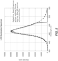
- Enhanced GFP has excitation and emission spectra in similar ranges, as shown in the graph of FIG. 1 .
- Exemplary spectral characteristics for filters for the optical apparatus of the present disclosure are based on EGFP values. It can be appreciated that different filter sets can be used, appropriately matched to the characteristics of the fluorescing agent within sample cells, as described in more detail subsequently.
- the treated cell sample acts as a sensory device, even slight changes in the host condition can be sensed in the physiologic response.
- the treated cell sample can be actively scanned and used to analyze the physiology of living biologic materials.
- Embodiments of the present disclosure address challenges (i) - (viii) given above and provide a compact, sensitive, and efficient solution for measurement of signals from within the host metabolism.
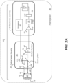
- FIG. 2A and signal flow diagram of FIG. 2B show component functions and operation for an embodiment of the present disclosure having an implantable sensor apparatus 100 configured for monitoring physiological condition of treated cells 12 sustained in a host organism 90.
- a cell sample chamber 10 provides an implantable housing suitable for treated cells that serve as sensor cells 12.
- Sensor cells 12 are treated to fluoresce in response to an illumination signal of an excitation wavelength.
- the fluorescence that can be sensed along a detection path exhibits changes in intensity in response to physiological change within the host organism 90.
- An optical port 14 for measuring the fluorescence energy changes is formed along one surface of cell sample chamber 10.
- the optical port 14 may include a transparent glass or plastic window, commonly shared for conveying light energy on both illumination and detection optical paths. Ongoing fluid communication is maintained between sensor cells 12 and the host organism.
- An optional permeable membrane shown in dashed line form as membrane 16 on another surface of chamber 10, can act as a microfluidic filter that provides a protective barrier between treated sensor cells 12 and other host organism cells, while at the same time allowing both continuous fluid communication or exchange and gas exchange to and from the host organism 90 in order to sustain cell 12 life.
- the treated sensor cells may reside on the interior surface of membrane 16, or on the interior surface of the (optional) transparent window, or in a suitable biocompatible matrix that is supported in position, such as between optical port 14 and membrane 16.
- Cell sample chamber 10 is configured to be coupled to an optical sensor housing 20.
- a coupling 22 fixes the position of optical port 14 of cell chamber 10 to a measurement window 24 of an optical chamber 30, along an optical axis OA.
- Any of a number of types of mechanisms can be used as coupling 22, including spring-loaded clips; one or more magnets; screws or other fasteners; and biocompatible adhesives, including pressure-sensitive tape or suitable epoxies (light or chemically cured).
- the coupling between cell chamber 10 and optical sensor housing 20 may include a gasket, an O-ring, or other mechanism for preventing fluid from entering the space between the optical port 14 and measurement window 24.
- an electronics assembly 50 is in signal communication with components within an optical chamber 30 in optical sensor housing 20 and provides the needed control and signal conditioning logic for obtaining measurements from sensor cells 12.
- electronics assembly 50 is packaged within optical sensor housing 20, such as formed on a circuit board that extends along a plane that is parallel to a plane defined by the primary optical paths for emitted fluorescent light and sensed light energy within optical chamber 30. This allows a single housing, implanted within the host organism 90, to enclose both the optics and the electronics needed for a wireless embodiment.
- optical sensor housing 20 is implanted and connected by wires or other communication channel to external electronics for signal control and measurement.
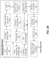
- the signal flow diagram of FIG. 2B shows the progression of optical and electrical signals through components of implantable sensor apparatus 100 and to external processing and storage components.
- An excitation optical filter F1 conditions emitted light from the solid-state excitation source 40.
- Filter F1 can be treated to attenuate unwanted excitation wavelengths from source 40, such as wavelengths from the excitation source that may be in the fluorescent emission signal range.
- Dichroic filter 34 is typically configured as a beam splitter, whose function is to separate excitation from fluorescence energy light paths, as described in more detail subsequently.
- the filtered light is directed to live sensor cells 12, which are treated to fluoresce when stimulated by excitation energy.
- the excitation light is typically in the blue range; the fluoresced sample signal light, at higher wavelengths, is typically in the green range.
- the fluoresced light signal from the sample sensor cells 12 is incident on the dichroic filter 34 beam splitter, which is conditioned to transmit the low-level fluoresced light, directed through emission filter F2, which is conditioned to attenuate and eliminate stray or scattered light outside of the fluorescent emission signal wavelength band.
- emission filter F2 is particularly useful for blocking any residual excitation light.
- the filtered fluorescent signal is converted from photons to electrons by a photodiode 42 or other suitable optical detector that generates a signal current.
- a trans-impedance amplifier 52 amplifies and converts the current signal to a voltage signal.
- An analog filter 54 removes noise from the voltage signal and provides the signal to an A/D converter 56 for digitization.
- the digital data that is generated is buffered in some type of memory circuit 62 and may be filtered by a digital filter 58.
- Transmitter 70 which is shown as a wireless transmitter in the FIG. 2B embodiment, transmits the digital data out of the host organism to a wireless receiver 120.
- the received data is buffered or recorded in a memory 122 and, optionally, is processed through a digital filter 124 and analyzed in order to provide a data file for subsequent processing.
- the process outlined with respect to FIG. 2B can be continuous if power is continuously delivered to components of sensor apparatus 100.
- the signal sequence shown in FIG. 2B can be executed in a time-varying fashion, for example, periodically or on demand, such as in response to wired or wireless instructions from outside the host organism.
- This time-varying approach can provide several advantages such as conserving battery power, limiting photobleaching of the live sensor cells, and improving signal quality (i.e. improving signal-to-noise ratio).
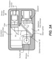
- Optical sensor housing 20 is sealed to protect optical components from contact with surrounding bodily fluid. As is shown more clearly in FIG. 3A , optical chamber 30 is partitioned into two optical sub-chambers 26 and 28 that are optically and spatially separated from each other to eliminate scattered excitation light or to reduce scattered excitation light so that its effect on the detected signal is negligible. This separation may be provided by a dichroic beam splitter 34, for example.
- Optical sub-chamber 26 houses an excitation source 40 that is energizable to generate illumination with light energy of an excitation wavelength for treated sensor cell 12 fluorescence.
- Excitation source 40 can be a light-emitting diode (LED) or other solid-state light source, such as a laser.
- Optical sub-chamber 28 houses an optical detector 42.
- Optical detector 42 can be a photodiode or other type of single or multi-element light sensor. Because of the low intensity of the fluorescence signal, optical detector 42 preferably has low noise and low dark current. In an alternative embodiment (not shown), optical detector 42 is a CCD or CMOS image sensor. In yet another embodiment, optical detector 42 is a chip-scale photodiode.
- FIG. 3B is a perspective view that shows, with exaggerated distance and partially exploded view, the arrangement of optical paths within optical sensor housing 20 and extending toward and back from cell chamber 10.
- the optical paths within a portion of optical chamber 30 are shared, with optical paths P1 and P2 both extending between a surface of beam splitter 34 and the sample, sensor cells 12 visible through window 24 and optical port 14, and with separate optical paths provided within optical chamber 30.
- Path P1 extends separately from path P2 in that section between the same surface of the beam splitter 34 and the excitation source 40.
- Detection path P2 is separate from path P1 between the opposing surface of beam splitter 34 and detector 42.
- 3A and 3B show an excitation light path P1 along a bold, solid line, with signal light path or detection path P2 marked as a dashed line path that extends toward detector 42 in optical sub-chamber 28.
- System optics define a folded optical axis OA that extends between the sensor cells 12 of the sample and the detector 42.
- FIG. 3C shows coupling/de-coupling of cell chamber 10 from window 24 on sensor housing 20.
- FIG. 3C also provides an idea of scale for an embodiment of the combined implantable sensor apparatus 100.
- the sensor housing 20 can be made as small as possible with rounded contours to minimize any injury or physical discomfort to the host.
- Beam splitter 34 can be a dichroic beam splitter, configured to transmit green light and reflect blue light wavelengths.
- the graph of FIG. 4 shows characteristic curves for transmission and reflection for an exemplary dichroic beam splitter component used as beam splitter 34. There is high reflectance for blue wavelength illumination from excitation source 40 (nominally 420-495 nm) and high transmission for green wavelengths fluoresced from sensor cells 12 (nominally 495-570 nm).
- Reflective surfaces 36 and 38 shown in FIGs. 3A and 3B can be used for redirecting the path of light within optical chamber 30.
- Right-angle prisms, mirrors, or other reflective surfaces can be used for this purpose.
- the light paths for excitation illumination and emitted fluorescent signal light to and from beam splitter 34 lie within the same "primary" plane, parallel to the page surface.
- Reflective surface 38 can be a turning prism for directing light into or out of the primary plane.
- Window 24 directs light into or out of the page, as indicated in FIG. 3A by the solid and hollow dots superimposed within window 24.
- a number of additional optical components can be disposed along optical paths P1 and P2 for improving efficiency and performance of the optical system.
- One or more bandpass filters F1 within excitation sub-chamber 26 can help to attenuate excitation wavelengths outside the intended range for excitation. Particularly important is that bandpass filters F1 must block any wavelengths from the excitation source that extend into the fluorescent emission signal range.
- FIG. 5 shows the results of filtering the excitation source with a suitable bandpass filter F1.
- one or more band pass filters F2. help to block stray or scattered light outside of the fluorescent emission signal wavelength band.
- the graph of FIG. 6 shows, for an embodiment of the present disclosure, the transmission characteristics for filters F1 and F2 over a range of wavelengths.
- the FIG. 6 graph can be compared against the input excitation and output emission spectra for enhanced green fluorescent protein (EGFP), given in FIG. 1 .
- EGFP enhanced green fluorescent protein
- one or more lenses L1 can be provided along the appropriate optical path for improving light focus and other features.
- optical chamber 30 serves to selectively combine and isolate the optical paths for excitation light energy and the sensed detection signal.
- the relative difference in energy level relates to the sizable difference in the ratio of excitation illumination photons to signal photons, a ratio in the range of about 1 million to 1 (1.0E+6 : 1) for relatively strong fluorescent signals to 1 billion to 1 (1.0E+8 : 1) for weak ones.
- optical sensor housing components include the following:
- electronics assembly 50 includes a transimpedance amplifier 52 for converting detector current to voltage and increasing the signal strength of the relatively weak signal from detector 42.
- An optional electronic filter 54 helps to significantly reduce the noise content, which can be inadvertently enhanced by amplifier 52.
- An analog-to-digital (A/D) converter 56 then converts the amplified sensed signal to a digital value.
- An optional digital filter 58 can provide further filtering of the digital signal.
- An on-board memory 62 stores measured data for transmission.
- a control logic processor 60 provides control of excitation source 40 in optical chamber 30 and controls the data acquisition sequence for obtaining signal data from detector 42.
- a transmitter 70 is in signal communication with processor 60 and is energizable to transmit measured data that has been processed by electronics assembly 50.
- the transmitted data can be received by an external processor (not shown) such as a computer that can store, process, and display the measured data, for example.
- Transmission can use a standard radio frequency (RF) wireless protocol, such as Bluetooth protocol (based on IEEE standard 802.15.1), accessible to a wide range of handheld communications devices as well as to a range of desktop and instrumentation systems.
- RF radio frequency
- Bluetooth protocol based on IEEE standard 802.15.1
- other wireless mechanisms can be used, including ultrasound.
- wireless receiver 120 acquires the transmitted signal and directs the digital content to memory 122.
- This signal data can be processed through optional digital filter 124 in order to provide the final data file.
- This example is for sensor cells that have enhanced green fluorescent protein (EGFP) and that have been biochemically stimulated to fluoresce.
- EGFP enhanced green fluorescent protein
- any residual ambient light such as light from a nearby lamp or window for example, that penetrates into the host.
- This can be accomplished by orienting the optical sensor housing and sample chamber so that the housing also serves as a light shield to block ambient light from the sample chamber and from the illumination and sample light paths.
- the housing is disposed toward the skin of the host with the sample chamber underneath.
- measurements are typically acquired at intervals. For example, measurements can be acquired every 20 minutes. However, measurements can be continuously obtained or taken on command.
- the measurement interval should take finite battery life into account. For such wireless embodiments, transmitted sensor data also consumes battery power; this additional requirement must be accounted for in the measurement power budget.
- battery power can be provided for operation.
- Batteries such as lithium ion or lithium polymer (LiPo) can be used.
- Radio frequency power can be employed wherein an antenna or coil on the sensor captures an RF signal provided by an external transmitter and the captured RF power is converted to suitable power for wireless sensor circuitry.
- Magnetic induction charging or magnetic resonance charging operate on similar principles to provide wireless energy.
- a charger source similar to that used in wireless charging for conventional cell phones can be used to effect wireless energy transfer and to charge rechargeable battery or other components.
- a flexible patch or other charge-receiving surface or component can be attached to or implanted within the host organism.
- DC power can be provided by a wired connection.
- FIG. 7A shows an exemplary unfiltered signal typical for a non-fluorescing cell sample, pulsed with excitation light for about one second.
- FIG. 7B shows an unfiltered signal typical for a cell sample that has been treated to fluoresce.
- FIG. 7C is a small interval (0.13 sec) of FIG. 7A that shows amplified noise from the 60Hz indoor ambient, as well as amplified pickup of higher frequency sources of ambient noise.
- background signal and noise can have significant impact on the ability to obtain sensitive measurements in the implantation environment.
- a variety of approaches can be implemented in order to improve measurement accuracy in the presence of the background and noise signal. For example, a combination of low-pass filtering and averaging can be used to measure the signal in FIGs. 7A and 7B to within a few tenths of a millivolt.
- Varying illumination intensity over time can also help to reduce noise levels in the resulting output signal. For example, several short fluorescence measurements can be performed and the results averaged to improve the signal to noise ratio.
- Alternative methods can include modulation of the illumination source at a fixed frequency, such as at 1 kHz, and using a bandpass electronic filter to measure the amplitude of the fixed-frequency fluorescent signal that is emitted.
- FIGS. 9A and 9B show the results of applying sinusoidal modulation to the illumination from excitation source 40 and using bandpass filtering.
- source 40 is an LED driven by a current that is modulated to obtain the desired time-varying light output.
- FIG. 9A shows the output signal for non-fluorescent cells.
- FIG. 9B shows typical output for fluorescing cells using source modulation.
- optical separation in sensor housing 20 between the input excitation light and the output emitted fluorescent light helps to eliminate or at least minimize the effects of scatter and reflection of excitation light towards optical detector 42. Additional approaches can supplement or replace the function of dichroic beam splitter 34 for providing the desired optical separation.
- the dichroic beam splitter 34 of FIGS. 3A and 3B is replaced by a polarization beam splitter (PBS), disposed at the same position.
- the polarization beam splitter reflects light having linear polarization along one axis and transmits light having linear polarization along the perpendicular axis.
- excitation source 40 provides linearly polarized excitation light along excitation light path P1.
- Excitation source 40 can be, for example, a LED with a linear polarizer or a laser that emits linearly polarized light.
- the linearly polarized excitation light is reflected by the polarization beam splitter towards cell chamber 10 and excites the sensor cells.
- Fluorescent light energy from the sensor cells is unpolarized, containing light with both polarization axes.
- the polarization beam splitter transmits fluorescent light that is polarized perpendicular to the excitation light polarization.
- the perpendicularly polarized fluoresced light is then measured by optical detector 42.
- the polarization beam splitter redirects, away from optical detector 42, both excitation light reflected by cell chamber 10 as well as that portion of fluoresced light that is polarized parallel to the excitation light.
- the polarization beam splitter may be used in conjunction with filters F1 and F2, as well as dichroic beam splitter 34.
- An additional linear polarizer may also be placed in front of optical detector 42 to further block misdirected excitation light.
- angular separation of the light paths is another possible alternative.
- FIG. 8 there is shown an embodiment of sensor housing 20 that employs angular separation of the excitation and fluorescent emission light paths.
- reflections of excitation light by the cell chamber or from other components are displaced from optical detector 42 as a result of the angular separation.
- Fluorescent emission that emerges from cell chamber 10, which has no preferential angular orientation, is measured directly by optical detector 42.
- an implantable apparatus for physiological measurement in a host organism comprising a) a sample chamber that is configured for implanting within the host organism, the chamber having a measurement port and live cells treated to fluoresce in response to light having an excitation wavelength; an optical sensor housing that is configured for implanting within the host organism, the optical sensor housing having: (i) a window disposed to convey excitation light output and receive fluorescent light from the live cells in the sample chamber; (ii) a coupling that couples the measurement port of the sample chamber in a fixed position relative to the window; (iii) an optical chamber that is partitioned into an excitation sub-chamber and a detection sub-chamber that is optically separated from the excitation sub-chamber, wherein both sub-chambers are in optical communication with the window; (iv) an excitation source that is energizable to direct light having the excitation wavelength along an excitation path through the excitation sub-chamber and to the window; (v) a detector that is disposed in the detection sub-
- the measurement port can include a transparent window.
- the optical sensor housing can be sealed from fluid intake and implanted within the host organism.
- the optical chamber can be partitioned by a beam splitter.
- the signal processing apparatus can be within the optical sensor housing.
- the signal processing apparatus can be energizable to transmit a wireless signal.
- the coupling can be a magnetic coupling, a fastener, a clip, an adhesive tape, or an adhesive, for example.
- the excitation source can be a light-emitting diode.
- the detector can be a photodiode.
- the sensor sub-chamber can have one or more surfaces treated to absorb scattered light.
- the signal processing apparatus can be further configured to receive one or more encoded instruction signals.
- the apparatus can have a battery.
- An implantable apparatus for reporting a physiological measurement from within a host organism can include an optical sensor housing that is configured for implanting within the host organism and that has a window and is energizable to generate an excitation light having an excitation wavelength, wherein the optical sensor housing is further configured to measure an emitted light from a sample, the emitted light having a fluorescent wavelength that is different from the excitation wavelength, wherein a ratio of excitation light photons to detected emitted light photons exceeds 100,000 to 1, and wherein the optical sensor housing is further configured to transmit a wireless signal indicative of the measured emitted light.
- a sample chamber can be configured for implanting within the host organism, the chamber having a measurement port and live cells, wherein the live cells are treated to fluoresce in response to the light having the excitation wavelength.
- a coupling can couple the measurement port of the sample chamber in a fixed position relative to the window of the optical sensor housing.
Landscapes
- Health & Medical Sciences (AREA)
- Life Sciences & Earth Sciences (AREA)
- General Health & Medical Sciences (AREA)
- Pathology (AREA)
- Engineering & Computer Science (AREA)
- Surgery (AREA)
- Veterinary Medicine (AREA)
- Heart & Thoracic Surgery (AREA)
- Medical Informatics (AREA)
- Molecular Biology (AREA)
- Physics & Mathematics (AREA)
- Animal Behavior & Ethology (AREA)
- Biomedical Technology (AREA)
- Public Health (AREA)
- Biophysics (AREA)
- Nuclear Medicine, Radiotherapy & Molecular Imaging (AREA)
- Chemical & Material Sciences (AREA)
- Analytical Chemistry (AREA)
- Biochemistry (AREA)
- General Physics & Mathematics (AREA)
- Immunology (AREA)
- Computer Networks & Wireless Communication (AREA)
- Investigating, Analyzing Materials By Fluorescence Or Luminescence (AREA)
Claims (14)
- Implantierbare Vorrichtung (100) zur physiologischen Messung in einem Wirtsorganismus, wobei die Vorrichtung umfasst:a) eine Probenkammer (10), die zum Implantieren innerhalb des Wirtsorganismus (90) konfiguriert ist, wobei die Probenkammer (10) eine Messöffnung (14) und lebende Zellen (12) aufweist, die so behandelt sind, dass sie in Reaktion auf Licht mit einer Anregungswellenlänge fluoreszieren, und wobei die Probenkammer so konfiguriert ist, dass sie eine Fluidverbindung zwischen den lebenden Zellen (12) und dem Wirtsorganismus (90) aufrechterhält;b) ein optisches Sensorgehäuse (20), das zum Implantieren innerhalb des Wirtsorganismus konfiguriert ist, und das so konfiguriert ist, dass es das in den Wirtsorganismus eindringende Umgebungslicht von der Probenkammer (10) abhält, wobei das optische Sensorgehäuse (20) Folgendes aufweist:(i) ein Fenster (24), das so angeordnet ist, dass es die Ausgabe von Anregungslicht in Richtung der Probenkammer leitet und Fluoreszenzlicht aus der Probenkammer empfängt;(ii) eine Kupplung, die die Messöffnung (14) der Probenkammer in einer festen Position relativ zu dem Fenster (24) koppelt;(iii) eine optische Kammer, die durch einen Strahlenteiler (34) in eine Anregungs-Unterkammer (26) und eine von der Anregungs-Unterkammer (26) optisch getrennte Detektions-Unterkammer (28) unterteilt ist, wobei beide Unterkammern in optischer Verbindung mit dem Fenster (24) stehen;(iv) eine Anregungsquelle (40), die erregbar ist, um Licht, das die Anregungswellenlänge aufweist, entlang eines Anregungspfades (P1) durch die Anregungs-Unterkammer (26) und auf das Fenster (24) zu richten;(v) einen Detektor (42), der in der Detektions-Unterkammer (28) in einem Pfad (P2) des von den lebenden Zellen (12) empfangenen Fluoreszenzlichts angeordnet ist;vi) eine reflektierende Oberfläche (38), die zwischen dem Strahlteiler (34) und der Probenkammer (10) angeordnet ist und Licht in eine und aus einer primären Ebene richtet, sodass der Anregungspfad (P1) und der Detektionspfad (P2) eine gefaltete optische Achse definieren, die sich zwischen den lebenden Zellen (12) der Probe und dem Detektor (42) erstreckt;
undc) eine Signalverarbeitungsvorrichtung, die in Signalkommunikation mit dem Detektor (42) steht und erregbar ist, um ein Detektorsignal zu erfassen und zu verarbeiten und ein verarbeitetes Signal zu übertragen, das Fluoreszenzlichtenergie anzeigt. - Vorrichtung (100) nach Anspruch 1, wobei die Probenkammer ferner eine durchlässige Membran (16) zur kontinuierlichen Aufrechterhaltung der Fluidverbindung umfasst.
- Vorrichtung (100) nach Anspruch 1, wobei die Messöffnung (14) ein transparentes Fenster (24) beinhaltet.
- Vorrichtung (100) nach Anspruch 1, wobei das optische Sensorgehäuse (20) gegen den Eintritt von Fluid abgedichtet und innerhalb des Wirtsorganismus implantiert ist.
- Vorrichtung (100) nach Anspruch 1, wobei sich die Signalverarbeitungsvorrichtung innerhalb des optischen Sensorgehäuses (20) befindet.
- Vorrichtung (100) nach Anspruch 1, wobei die Signalverarbeitungsvorrichtung erregbar ist, um ein drahtloses Signal zu übertragen.
- Vorrichtung (100) nach Anspruch 1, wobei die Kupplung aus der Gruppe bestehend aus einer magnetischen Kupplung, einem Verschluss, einem Clip, einem Klebeband und einem Klebstoff stammt.
- Vorrichtung (100) nach Anspruch 1 wobei die Anregungsquelle (40) eine lichtemittierende Diode ist.
- Vorrichtung (100) nach Anspruch 1, wobei der Detektor (42) eine Photodiode ist.
- Vorrichtung (100) nach Anspruch 1, wobei die Detektions-Unterkammer (28) eine oder mehrere Oberflächen aufweist, die so behandelt sind, dass sie gestreutes Licht absorbieren.
- Vorrichtung (100) nach Anspruch 1, ferner umfassend einen oder mehrere optische Filter (F1, F2) entlang eines oder beider des Detektionspfads (P2) und des Anregungspfads (P1).
- Vorrichtung (100) nach Anspruch 1, wobei die Signalverarbeitungsvorrichtung ferner so konfiguriert ist, dass sie ein oder mehrere kodierte Anweisungssignale empfängt.
- Vorrichtung (100) nach Anspruch 1, ferner umfassend eine Batterie, wobei die Batterie optional durch drahtlose Energieübertragung wiederaufladbar ist.
- Verfahren zum Erfassen einer physiologischen Messung innerhalb eines Wirtsorganismus, wobei das Verfahren Folgendes umfasst:a) Aufrechterhalten einer Fluidverbindung zwischen dem Wirtsorganismus und lebenden Zellen (12), die innerhalb einer in den Wirtsorganismus implantierten Probenkammer erhalten werden, wobei die lebenden Zellen (12) so behandelt werden, dass sie als Reaktion auf Anregungslichtenergie fluoreszieren;b) innerhalb des Wirtsorganismus, Richten eines Anregungslichts, das eine Anregungswellenlänge und eine Beleuchtungsintensität aufweist, entlang eines Lichtpfads, der eine reflektierende Oberfläche (38) umfasst, die das Licht aus einer primären Ebene heraus richtet, sodass der Lichtpfad (P1, P2) eine gefaltete optische Achse definiert, die sich in die Probenkammer erstreckt;c) Sammeln der aus der Probenkammer austretenden fluoreszierten Lichtenergie;d) Trennen der fluoreszierten Lichtenergie von einer restlichen Anregungslichtenergie entlang des Pfades mit einem Strahlenteiler (34) und Erfassen des fluoreszierten Lichts an einem Detektor (42), der so konfiguriert ist, dass er ein Detektorausgangssignal entsprechend der erfassten fluoreszierten Lichtenergie erzeugt;e) Verstärken und Digitalisieren des Detektor-Ausgabesignals, um digitale Daten zu erzeugen;f) Übertragen der digitalen Daten innerhalb des Wirtsorganismus an einen Empfänger, der sich außerhalb des Wirtsorganismus befindet;
undg) Speichern der übertragenen digitalen Daten in einem Speicher, der in Signalverbindung mit dem Empfänger steht und sich außerhalb des Wirtsorganismus befindet; undh) in einem oder mehreren Zeitintervallen, Wiederholen der Schritte (a)-(g), während die Beleuchtungsintensität und/oder die Anregungswellenlänge von der Anregungsquelle (40) variiert wird.
Applications Claiming Priority (2)
| Application Number | Priority Date | Filing Date | Title |
|---|---|---|---|
| US201962844165P | 2019-05-07 | 2019-05-07 | |
| PCT/US2020/031568 WO2020227342A1 (en) | 2019-05-07 | 2020-05-06 | Implantable apparatus for sensing biologic signals |
Publications (3)
| Publication Number | Publication Date |
|---|---|
| EP3965656A1 EP3965656A1 (de) | 2022-03-16 |
| EP3965656A4 EP3965656A4 (de) | 2022-12-14 |
| EP3965656B1 true EP3965656B1 (de) | 2024-04-10 |
Family
ID=73047444
Family Applications (1)
| Application Number | Title | Priority Date | Filing Date |
|---|---|---|---|
| EP20802889.4A Active EP3965656B1 (de) | 2019-05-07 | 2020-05-06 | Implantierbare vorrichtung zur erfassung von biologischen signalen |
Country Status (6)
| Country | Link |
|---|---|
| US (2) | US11877866B2 (de) |
| EP (1) | EP3965656B1 (de) |
| KR (1) | KR20220005000A (de) |
| CA (1) | CA3139095A1 (de) |
| ES (1) | ES2980068T3 (de) |
| WO (1) | WO2020227342A1 (de) |
Families Citing this family (3)
| Publication number | Priority date | Publication date | Assignee | Title |
|---|---|---|---|---|
| ES2980068T3 (es) * | 2019-05-07 | 2024-09-27 | Efferent Labs Inc | Aparato implantable para detectar señales biológicas |
| DE102019123404B4 (de) * | 2019-09-02 | 2024-02-15 | Bayerische Motoren Werke Aktiengesellschaft | Sensorvorrichtung und Fahrassistenzsystem |
| WO2025206016A1 (ja) * | 2024-03-27 | 2025-10-02 | 国立研究開発法人理化学研究所 | 蛍光観察装置 |
Family Cites Families (14)
| Publication number | Priority date | Publication date | Assignee | Title |
|---|---|---|---|---|
| JP2006512109A (ja) * | 2002-08-01 | 2006-04-13 | ザ ジョンズ ホプキンズ ユニバーシティ | 蛍光発光を用いた、分子構造の特定技術、および身体内腔の内側に並ぶ細胞種の治療技術 |
| WO2006041738A2 (en) * | 2004-10-04 | 2006-04-20 | Cyberkinetics Neurotechnology Systems, Inc. | Biological interface system |
| DE102005035932A1 (de) * | 2005-07-28 | 2007-02-08 | Endress + Hauser Conducta Gesellschaft für Mess- und Regeltechnik mbH + Co. KG | Optischer Sensor für in-situ Messungen |
| US20160324449A1 (en) * | 2006-03-28 | 2016-11-10 | Glusense Ltd. | Implantable sensors |
| US20100202966A1 (en) | 2006-03-28 | 2010-08-12 | Yossi Gross | Implantable Sensor |
| CN102333478B (zh) * | 2008-12-24 | 2014-12-10 | 葡萄糖传感器公司 | 可植入的光学葡萄糖感测 |
| US9146230B2 (en) * | 2011-06-20 | 2015-09-29 | Yoram Palti | Continuous monitoring of glucose and other living body constituents |
| US9539329B2 (en) * | 2011-08-31 | 2017-01-10 | The General Hospital Corporation | Light-guiding hydrogel devices for cell-based sensing and therapy |
| DE102011087679B3 (de) * | 2011-12-02 | 2013-04-18 | Schildtec GmbH | Meßkammer für einen optisch arbeitenden Sensor zum Bestimmen einer Konzentration eines Stoffes |
| US9225190B2 (en) | 2012-09-07 | 2015-12-29 | Manufacturers And Traders Trust Company | Implant current controlled battery charging based on temperature |
| US10149640B2 (en) * | 2014-06-16 | 2018-12-11 | The Regents Of The University Of California | Measuring oxygen levels in an implant, and implants having incorporated oxygen sensing |
| JP6888779B2 (ja) * | 2016-03-31 | 2021-06-16 | 国立大学法人弘前大学 | 多面画像取得システム、観察装置、観察方法、スクリーニング方法、および被写体の立体再構成方法 |
| CN115868982B (zh) * | 2017-04-19 | 2025-10-10 | 传感技术股份有限公司 | 对分析物指示剂变化的检测和修正 |
| ES2980068T3 (es) * | 2019-05-07 | 2024-09-27 | Efferent Labs Inc | Aparato implantable para detectar señales biológicas |
-
2020
- 2020-05-06 ES ES20802889T patent/ES2980068T3/es active Active
- 2020-05-06 KR KR1020217036212A patent/KR20220005000A/ko not_active Ceased
- 2020-05-06 CA CA3139095A patent/CA3139095A1/en active Pending
- 2020-05-06 EP EP20802889.4A patent/EP3965656B1/de active Active
- 2020-05-06 US US16/867,697 patent/US11877866B2/en active Active
- 2020-05-06 WO PCT/US2020/031568 patent/WO2020227342A1/en not_active Ceased
-
2023
- 2023-12-29 US US18/399,914 patent/US20240130684A1/en not_active Abandoned
Also Published As
| Publication number | Publication date |
|---|---|
| EP3965656A4 (de) | 2022-12-14 |
| US11877866B2 (en) | 2024-01-23 |
| US20240130684A1 (en) | 2024-04-25 |
| ES2980068T3 (es) | 2024-09-27 |
| KR20220005000A (ko) | 2022-01-12 |
| CA3139095A1 (en) | 2020-11-12 |
| EP3965656A1 (de) | 2022-03-16 |
| WO2020227342A1 (en) | 2020-11-12 |
| US20200352513A1 (en) | 2020-11-12 |
Similar Documents
| Publication | Publication Date | Title |
|---|---|---|
| US20240130684A1 (en) | Implantable apparatus for sensing biologic signals | |
| KR100911887B1 (ko) | 이식된 센서 처리 시스템 및 방법 | |
| CN106999118B (zh) | 分析物感测装置 | |
| US8126531B2 (en) | Miniature spectrometer | |
| ES2995163T3 (en) | Detecting and correcting for changes to an analyte indicator | |
| AU2004250213A1 (en) | System, device and method for exciting a sensor and detecting analyte | |
| KR20210114503A (ko) | 질병의 시각화를 위한 모듈식 내시경 시스템 | |
| AU2002216747A1 (en) | Implanted sensor processing system and method | |
| JP2000506410A (ja) | 移植可能なバイオセンシングトランスポンダ | |
| US20040054385A1 (en) | Implanted sensor processing system and method | |
| CN102906559A (zh) | 用于使用光测量诸如胆红素的分析物的装置和方法 | |
| WO2002061405A2 (en) | Method and hand-held device for fluorescence detection | |
| CA2956779C (en) | Miniature multi-target optical imaging apparatus | |
| US8471221B2 (en) | Device for measuring fluorescent radiation on biological substances with a semi-conductor sensor arrangement | |
| Reble et al. | No More Sunburn: Non‐invasive LED‐based measurement of the sun protection factor | |
| CA3061013C (en) | Detecting and correcting for changes to an analyte indicator | |
| Wilson et al. | Monitoring the dynamics of tissue oxygenation in vivo by phosphorescence quenching | |
| CN120130939A (zh) | 一种荧光光度计探针结构及无线深脑探针系统 | |
| Grattan et al. | Biomedical thermometry-a simple fiber optic approach | |
| CZ303501B6 (cs) | Zarízení pro optické snímání elektrické aktivity živé tkáne | |
| Alfano et al. | Phosphorescence and Fluorescence Measurements of Human Tissues Using UV LED Excitation |
Legal Events
| Date | Code | Title | Description |
|---|---|---|---|
| STAA | Information on the status of an ep patent application or granted ep patent |
Free format text: STATUS: THE INTERNATIONAL PUBLICATION HAS BEEN MADE |
|
| PUAI | Public reference made under article 153(3) epc to a published international application that has entered the european phase |
Free format text: ORIGINAL CODE: 0009012 |
|
| STAA | Information on the status of an ep patent application or granted ep patent |
Free format text: STATUS: REQUEST FOR EXAMINATION WAS MADE |
|
| 17P | Request for examination filed |
Effective date: 20211007 |
|
| AK | Designated contracting states |
Kind code of ref document: A1 Designated state(s): AL AT BE BG CH CY CZ DE DK EE ES FI FR GB GR HR HU IE IS IT LI LT LU LV MC MK MT NL NO PL PT RO RS SE SI SK SM TR |
|
| DAV | Request for validation of the european patent (deleted) | ||
| DAX | Request for extension of the european patent (deleted) | ||
| A4 | Supplementary search report drawn up and despatched |
Effective date: 20221110 |
|
| RIC1 | Information provided on ipc code assigned before grant |
Ipc: A61B 5/1459 20060101ALI20221104BHEP Ipc: A61B 5/1455 20060101ALI20221104BHEP Ipc: A61B 5/00 20060101ALI20221104BHEP Ipc: A61B 5/145 20060101AFI20221104BHEP |
|
| GRAP | Despatch of communication of intention to grant a patent |
Free format text: ORIGINAL CODE: EPIDOSNIGR1 |
|
| STAA | Information on the status of an ep patent application or granted ep patent |
Free format text: STATUS: GRANT OF PATENT IS INTENDED |
|
| INTG | Intention to grant announced |
Effective date: 20231127 |
|
| GRAS | Grant fee paid |
Free format text: ORIGINAL CODE: EPIDOSNIGR3 |
|
| GRAA | (expected) grant |
Free format text: ORIGINAL CODE: 0009210 |
|
| STAA | Information on the status of an ep patent application or granted ep patent |
Free format text: STATUS: THE PATENT HAS BEEN GRANTED |
|
| AK | Designated contracting states |
Kind code of ref document: B1 Designated state(s): AL AT BE BG CH CY CZ DE DK EE ES FI FR GB GR HR HU IE IS IT LI LT LU LV MC MK MT NL NO PL PT RO RS SE SI SK SM TR |
|
| REG | Reference to a national code |
Ref country code: GB Ref legal event code: FG4D |
|
| REG | Reference to a national code |
Ref country code: CH Ref legal event code: EP |
|
| REG | Reference to a national code |
Ref country code: DE Ref legal event code: R096 Ref document number: 602020028867 Country of ref document: DE |
|
| REG | Reference to a national code |
Ref country code: IE Ref legal event code: FG4D |
|
| P01 | Opt-out of the competence of the unified patent court (upc) registered |
Free format text: CASE NUMBER: APP_33946/2024 Effective date: 20240606 |
|
| REG | Reference to a national code |
Ref country code: LT Ref legal event code: MG9D |
|
| REG | Reference to a national code |
Ref country code: NL Ref legal event code: MP Effective date: 20240410 |
|
| REG | Reference to a national code |
Ref country code: AT Ref legal event code: MK05 Ref document number: 1674039 Country of ref document: AT Kind code of ref document: T Effective date: 20240410 |
|
| PG25 | Lapsed in a contracting state [announced via postgrant information from national office to epo] |
Ref country code: NL Free format text: LAPSE BECAUSE OF FAILURE TO SUBMIT A TRANSLATION OF THE DESCRIPTION OR TO PAY THE FEE WITHIN THE PRESCRIBED TIME-LIMIT Effective date: 20240410 |
|
| REG | Reference to a national code |
Ref country code: ES Ref legal event code: FG2A Ref document number: 2980068 Country of ref document: ES Kind code of ref document: T3 Effective date: 20240927 |
|
| PG25 | Lapsed in a contracting state [announced via postgrant information from national office to epo] |
Ref country code: NL Free format text: LAPSE BECAUSE OF FAILURE TO SUBMIT A TRANSLATION OF THE DESCRIPTION OR TO PAY THE FEE WITHIN THE PRESCRIBED TIME-LIMIT Effective date: 20240410 |
|
| PG25 | Lapsed in a contracting state [announced via postgrant information from national office to epo] |
Ref country code: IS Free format text: LAPSE BECAUSE OF FAILURE TO SUBMIT A TRANSLATION OF THE DESCRIPTION OR TO PAY THE FEE WITHIN THE PRESCRIBED TIME-LIMIT Effective date: 20240810 |
|
| PG25 | Lapsed in a contracting state [announced via postgrant information from national office to epo] |
Ref country code: BG Free format text: LAPSE BECAUSE OF FAILURE TO SUBMIT A TRANSLATION OF THE DESCRIPTION OR TO PAY THE FEE WITHIN THE PRESCRIBED TIME-LIMIT Effective date: 20240410 |
|
| PG25 | Lapsed in a contracting state [announced via postgrant information from national office to epo] |
Ref country code: HR Free format text: LAPSE BECAUSE OF FAILURE TO SUBMIT A TRANSLATION OF THE DESCRIPTION OR TO PAY THE FEE WITHIN THE PRESCRIBED TIME-LIMIT Effective date: 20240410 Ref country code: FI Free format text: LAPSE BECAUSE OF FAILURE TO SUBMIT A TRANSLATION OF THE DESCRIPTION OR TO PAY THE FEE WITHIN THE PRESCRIBED TIME-LIMIT Effective date: 20240410 |
|
| PG25 | Lapsed in a contracting state [announced via postgrant information from national office to epo] |
Ref country code: GR Free format text: LAPSE BECAUSE OF FAILURE TO SUBMIT A TRANSLATION OF THE DESCRIPTION OR TO PAY THE FEE WITHIN THE PRESCRIBED TIME-LIMIT Effective date: 20240711 |
|
| PG25 | Lapsed in a contracting state [announced via postgrant information from national office to epo] |
Ref country code: PT Free format text: LAPSE BECAUSE OF FAILURE TO SUBMIT A TRANSLATION OF THE DESCRIPTION OR TO PAY THE FEE WITHIN THE PRESCRIBED TIME-LIMIT Effective date: 20240812 |
|
| PG25 | Lapsed in a contracting state [announced via postgrant information from national office to epo] |
Ref country code: AT Free format text: LAPSE BECAUSE OF FAILURE TO SUBMIT A TRANSLATION OF THE DESCRIPTION OR TO PAY THE FEE WITHIN THE PRESCRIBED TIME-LIMIT Effective date: 20240410 |
|
| PG25 | Lapsed in a contracting state [announced via postgrant information from national office to epo] |
Ref country code: PL Free format text: LAPSE BECAUSE OF FAILURE TO SUBMIT A TRANSLATION OF THE DESCRIPTION OR TO PAY THE FEE WITHIN THE PRESCRIBED TIME-LIMIT Effective date: 20240410 |
|
| PG25 | Lapsed in a contracting state [announced via postgrant information from national office to epo] |
Ref country code: LV Free format text: LAPSE BECAUSE OF FAILURE TO SUBMIT A TRANSLATION OF THE DESCRIPTION OR TO PAY THE FEE WITHIN THE PRESCRIBED TIME-LIMIT Effective date: 20240410 |
|
| PG25 | Lapsed in a contracting state [announced via postgrant information from national office to epo] |
Ref country code: PT Free format text: LAPSE BECAUSE OF FAILURE TO SUBMIT A TRANSLATION OF THE DESCRIPTION OR TO PAY THE FEE WITHIN THE PRESCRIBED TIME-LIMIT Effective date: 20240812 Ref country code: PL Free format text: LAPSE BECAUSE OF FAILURE TO SUBMIT A TRANSLATION OF THE DESCRIPTION OR TO PAY THE FEE WITHIN THE PRESCRIBED TIME-LIMIT Effective date: 20240410 Ref country code: NO Free format text: LAPSE BECAUSE OF FAILURE TO SUBMIT A TRANSLATION OF THE DESCRIPTION OR TO PAY THE FEE WITHIN THE PRESCRIBED TIME-LIMIT Effective date: 20240710 Ref country code: LV Free format text: LAPSE BECAUSE OF FAILURE TO SUBMIT A TRANSLATION OF THE DESCRIPTION OR TO PAY THE FEE WITHIN THE PRESCRIBED TIME-LIMIT Effective date: 20240410 Ref country code: IS Free format text: LAPSE BECAUSE OF FAILURE TO SUBMIT A TRANSLATION OF THE DESCRIPTION OR TO PAY THE FEE WITHIN THE PRESCRIBED TIME-LIMIT Effective date: 20240810 Ref country code: HR Free format text: LAPSE BECAUSE OF FAILURE TO SUBMIT A TRANSLATION OF THE DESCRIPTION OR TO PAY THE FEE WITHIN THE PRESCRIBED TIME-LIMIT Effective date: 20240410 Ref country code: GR Free format text: LAPSE BECAUSE OF FAILURE TO SUBMIT A TRANSLATION OF THE DESCRIPTION OR TO PAY THE FEE WITHIN THE PRESCRIBED TIME-LIMIT Effective date: 20240711 Ref country code: FI Free format text: LAPSE BECAUSE OF FAILURE TO SUBMIT A TRANSLATION OF THE DESCRIPTION OR TO PAY THE FEE WITHIN THE PRESCRIBED TIME-LIMIT Effective date: 20240410 Ref country code: BG Free format text: LAPSE BECAUSE OF FAILURE TO SUBMIT A TRANSLATION OF THE DESCRIPTION OR TO PAY THE FEE WITHIN THE PRESCRIBED TIME-LIMIT Effective date: 20240410 Ref country code: AT Free format text: LAPSE BECAUSE OF FAILURE TO SUBMIT A TRANSLATION OF THE DESCRIPTION OR TO PAY THE FEE WITHIN THE PRESCRIBED TIME-LIMIT Effective date: 20240410 Ref country code: RS Free format text: LAPSE BECAUSE OF FAILURE TO SUBMIT A TRANSLATION OF THE DESCRIPTION OR TO PAY THE FEE WITHIN THE PRESCRIBED TIME-LIMIT Effective date: 20240710 |
|
| REG | Reference to a national code |
Ref country code: CH Ref legal event code: PL |
|
| REG | Reference to a national code |
Ref country code: DE Ref legal event code: R097 Ref document number: 602020028867 Country of ref document: DE |
|
| PG25 | Lapsed in a contracting state [announced via postgrant information from national office to epo] |
Ref country code: DK Free format text: LAPSE BECAUSE OF FAILURE TO SUBMIT A TRANSLATION OF THE DESCRIPTION OR TO PAY THE FEE WITHIN THE PRESCRIBED TIME-LIMIT Effective date: 20240410 |
|
| PG25 | Lapsed in a contracting state [announced via postgrant information from national office to epo] |
Ref country code: LU Free format text: LAPSE BECAUSE OF NON-PAYMENT OF DUE FEES Effective date: 20240506 |
|
| PG25 | Lapsed in a contracting state [announced via postgrant information from national office to epo] |
Ref country code: EE Free format text: LAPSE BECAUSE OF FAILURE TO SUBMIT A TRANSLATION OF THE DESCRIPTION OR TO PAY THE FEE WITHIN THE PRESCRIBED TIME-LIMIT Effective date: 20240410 |
|
| PG25 | Lapsed in a contracting state [announced via postgrant information from national office to epo] |
Ref country code: CZ Free format text: LAPSE BECAUSE OF FAILURE TO SUBMIT A TRANSLATION OF THE DESCRIPTION OR TO PAY THE FEE WITHIN THE PRESCRIBED TIME-LIMIT Effective date: 20240410 |
|
| PG25 | Lapsed in a contracting state [announced via postgrant information from national office to epo] |
Ref country code: SK Free format text: LAPSE BECAUSE OF FAILURE TO SUBMIT A TRANSLATION OF THE DESCRIPTION OR TO PAY THE FEE WITHIN THE PRESCRIBED TIME-LIMIT Effective date: 20240410 Ref country code: RO Free format text: LAPSE BECAUSE OF FAILURE TO SUBMIT A TRANSLATION OF THE DESCRIPTION OR TO PAY THE FEE WITHIN THE PRESCRIBED TIME-LIMIT Effective date: 20240410 |
|
| PG25 | Lapsed in a contracting state [announced via postgrant information from national office to epo] |
Ref country code: SM Free format text: LAPSE BECAUSE OF FAILURE TO SUBMIT A TRANSLATION OF THE DESCRIPTION OR TO PAY THE FEE WITHIN THE PRESCRIBED TIME-LIMIT Effective date: 20240410 |
|
| PG25 | Lapsed in a contracting state [announced via postgrant information from national office to epo] |
Ref country code: SM Free format text: LAPSE BECAUSE OF FAILURE TO SUBMIT A TRANSLATION OF THE DESCRIPTION OR TO PAY THE FEE WITHIN THE PRESCRIBED TIME-LIMIT Effective date: 20240410 Ref country code: SK Free format text: LAPSE BECAUSE OF FAILURE TO SUBMIT A TRANSLATION OF THE DESCRIPTION OR TO PAY THE FEE WITHIN THE PRESCRIBED TIME-LIMIT Effective date: 20240410 Ref country code: RO Free format text: LAPSE BECAUSE OF FAILURE TO SUBMIT A TRANSLATION OF THE DESCRIPTION OR TO PAY THE FEE WITHIN THE PRESCRIBED TIME-LIMIT Effective date: 20240410 Ref country code: LU Free format text: LAPSE BECAUSE OF NON-PAYMENT OF DUE FEES Effective date: 20240506 Ref country code: EE Free format text: LAPSE BECAUSE OF FAILURE TO SUBMIT A TRANSLATION OF THE DESCRIPTION OR TO PAY THE FEE WITHIN THE PRESCRIBED TIME-LIMIT Effective date: 20240410 Ref country code: DK Free format text: LAPSE BECAUSE OF FAILURE TO SUBMIT A TRANSLATION OF THE DESCRIPTION OR TO PAY THE FEE WITHIN THE PRESCRIBED TIME-LIMIT Effective date: 20240410 Ref country code: CZ Free format text: LAPSE BECAUSE OF FAILURE TO SUBMIT A TRANSLATION OF THE DESCRIPTION OR TO PAY THE FEE WITHIN THE PRESCRIBED TIME-LIMIT Effective date: 20240410 Ref country code: MC Free format text: LAPSE BECAUSE OF FAILURE TO SUBMIT A TRANSLATION OF THE DESCRIPTION OR TO PAY THE FEE WITHIN THE PRESCRIBED TIME-LIMIT Effective date: 20240410 Ref country code: CH Free format text: LAPSE BECAUSE OF NON-PAYMENT OF DUE FEES Effective date: 20240531 |
|
| PLBE | No opposition filed within time limit |
Free format text: ORIGINAL CODE: 0009261 |
|
| STAA | Information on the status of an ep patent application or granted ep patent |
Free format text: STATUS: NO OPPOSITION FILED WITHIN TIME LIMIT |
|
| REG | Reference to a national code |
Ref country code: BE Ref legal event code: MM Effective date: 20240531 |
|
| 26N | No opposition filed |
Effective date: 20250113 |
|
| PG25 | Lapsed in a contracting state [announced via postgrant information from national office to epo] |
Ref country code: IE Free format text: LAPSE BECAUSE OF NON-PAYMENT OF DUE FEES Effective date: 20240506 |
|
| PG25 | Lapsed in a contracting state [announced via postgrant information from national office to epo] |
Ref country code: BE Free format text: LAPSE BECAUSE OF NON-PAYMENT OF DUE FEES Effective date: 20240531 Ref country code: SI Free format text: LAPSE BECAUSE OF FAILURE TO SUBMIT A TRANSLATION OF THE DESCRIPTION OR TO PAY THE FEE WITHIN THE PRESCRIBED TIME-LIMIT Effective date: 20240410 |
|
| PGFP | Annual fee paid to national office [announced via postgrant information from national office to epo] |
Ref country code: DE Payment date: 20250521 Year of fee payment: 6 |
|
| PGFP | Annual fee paid to national office [announced via postgrant information from national office to epo] |
Ref country code: GB Payment date: 20250527 Year of fee payment: 6 |
|
| PGFP | Annual fee paid to national office [announced via postgrant information from national office to epo] |
Ref country code: IT Payment date: 20250527 Year of fee payment: 6 |
|
| PGFP | Annual fee paid to national office [announced via postgrant information from national office to epo] |
Ref country code: FR Payment date: 20250528 Year of fee payment: 6 |
|
| PG25 | Lapsed in a contracting state [announced via postgrant information from national office to epo] |
Ref country code: CY Free format text: LAPSE BECAUSE OF FAILURE TO SUBMIT A TRANSLATION OF THE DESCRIPTION OR TO PAY THE FEE WITHIN THE PRESCRIBED TIME-LIMIT; INVALID AB INITIO Effective date: 20200506 |
|
| PG25 | Lapsed in a contracting state [announced via postgrant information from national office to epo] |
Ref country code: HU Free format text: LAPSE BECAUSE OF FAILURE TO SUBMIT A TRANSLATION OF THE DESCRIPTION OR TO PAY THE FEE WITHIN THE PRESCRIBED TIME-LIMIT; INVALID AB INITIO Effective date: 20200506 |
|
| PG25 | Lapsed in a contracting state [announced via postgrant information from national office to epo] |
Ref country code: SE Free format text: LAPSE BECAUSE OF FAILURE TO SUBMIT A TRANSLATION OF THE DESCRIPTION OR TO PAY THE FEE WITHIN THE PRESCRIBED TIME-LIMIT Effective date: 20240410 |
|
| PGFP | Annual fee paid to national office [announced via postgrant information from national office to epo] |
Ref country code: ES Payment date: 20250630 Year of fee payment: 6 |