EP3965609B1 - Teleskopgriff - Google Patents
Teleskopgriff Download PDFInfo
- Publication number
- EP3965609B1 EP3965609B1 EP20742444.1A EP20742444A EP3965609B1 EP 3965609 B1 EP3965609 B1 EP 3965609B1 EP 20742444 A EP20742444 A EP 20742444A EP 3965609 B1 EP3965609 B1 EP 3965609B1
- Authority
- EP
- European Patent Office
- Prior art keywords
- handle
- condition
- elongated element
- central elongated
- handle part
- Prior art date
- Legal status (The legal status is an assumption and is not a legal conclusion. Google has not performed a legal analysis and makes no representation as to the accuracy of the status listed.)
- Active
Links
Images



Classifications
-
- A—HUMAN NECESSITIES
- A45—HAND OR TRAVELLING ARTICLES
- A45C—PURSES; LUGGAGE; HAND CARRIED BAGS
- A45C13/00—Details; Accessories
- A45C13/26—Special adaptations of handles
- A45C13/262—Special adaptations of handles for wheeled luggage
-
- A—HUMAN NECESSITIES
- A45—HAND OR TRAVELLING ARTICLES
- A45C—PURSES; LUGGAGE; HAND CARRIED BAGS
- A45C13/00—Details; Accessories
- A45C13/001—Accessories
-
- A—HUMAN NECESSITIES
- A45—HAND OR TRAVELLING ARTICLES
- A45C—PURSES; LUGGAGE; HAND CARRIED BAGS
- A45C13/00—Details; Accessories
- A45C13/26—Special adaptations of handles
-
- A—HUMAN NECESSITIES
- A45—HAND OR TRAVELLING ARTICLES
- A45C—PURSES; LUGGAGE; HAND CARRIED BAGS
- A45C5/00—Rigid or semi-rigid luggage
- A45C5/03—Suitcases
-
- A—HUMAN NECESSITIES
- A45—HAND OR TRAVELLING ARTICLES
- A45C—PURSES; LUGGAGE; HAND CARRIED BAGS
- A45C5/00—Rigid or semi-rigid luggage
- A45C5/04—Trunks; Travelling baskets
-
- A—HUMAN NECESSITIES
- A45—HAND OR TRAVELLING ARTICLES
- A45C—PURSES; LUGGAGE; HAND CARRIED BAGS
- A45C13/00—Details; Accessories
- A45C13/26—Special adaptations of handles
- A45C13/262—Special adaptations of handles for wheeled luggage
- A45C2013/267—Special adaptations of handles for wheeled luggage the handle being slidable, extractable and lockable in one or more positions
Definitions
- the present invention relates to a telescopic handle for transportable containers, such as suitcases, trolley cases or the like, according to the preamble of claim 1.
- the present invention relates in particular to the field of manufacture of travel containers such as suitcases, trolley cases and other luggage.
- a critical aspect of the trolley cases known in the state of the art is the telescopic handles, which allow the trolley case to be gripped and facilitate its transport.
- Each rod is generally made up of two or more tubular elements which slide inside each other in order to limit the sizes, once such rods are in retracted condition.
- fixing pins that have a dual function, as some pins lock one tubular element with respect to another one avoiding sliding, while other pins engage in appropriate engagement seats provided on the trolley case, to avoid the retraction of the rods inside the trolley case.
- the handles In trolley cases known in the state of the art, the handles generally have a button which allows the pins to be activated/deactivated.
- Such button represents a critical part of the trolley case handles known in the state of the art, as it is often subject to breakages, of the button itself or of the mechanism which controls it.
- the breakages are mainly due to possible impacts that the trolley case undergoes during transport and during positioning in aircraft holds/overhead locker, as well as in the car luggage compartments.
- the button also has an aesthetically unpleasant appearance, which disturbs the continuity of the profiles and surfaces of the trolley case.
- Each of the telescopic handles includes a first tube, a second tube into which the first tube is telescopically insertable, a tubular anchor with an upper tip attached to a lower tip of the first tube, a lower portion defining a plurality of slits so that the lower portion of the tubular anchor can be expanded easily, a link insertable through the first tube, a plug attached to a lower tip of the link.
- the plug can be moved to an upper position by pulling the link for abutting the lower portion of the tubular anchor against the first tube for restraining the first tube relative to the second tube.
- the plug can be moved to a lower position by pushing the link for releasing the lower portion of the tubular anchor from the first tube for allowing the movement of the first tube in respect to the second tube.
- Each of two link-driving devices is connected between a grip and one of the telescopic handles.
- the links can be driven by means of the link-driving devices by pivoting the grip.
- a handle of a telescopic handle assembly for a baggage cart which includes at least a handle seat fixedly connected to an inner tube of the telescopic handle assembly, an actuator rotatably received within a mounting hole of the handle seat, a grip portion formed by an assembly of two grip members with semi-circular peripheries and being fixedly connected to the actuator so that a rotation of the grip portion can rotate the actuator, and an operating block which has at least a portion being forcedly in contact with a portion of the actuator so that a rotation of the actuator can cause a lifting movement of the operating block from a position to a selected position.
- the operating block is fixedly connected to a locking means for locking the inner tube with an outer tube of the telescopic handle assembly. Once the operating block is lifted to the selected position, the locking of the locking means for locking the inner tube with the outer tube is unlocked.
- a handle assembly for a wheeled luggage case includes two outer tubes, two inner tubes respectively and retractably received in the two outer tubes, a rotated handle connected between the two inner tubes, two actuating means respectively in the inner tubes, and two rods received in the inner tubes and operatably engaged with the actuating means.
- the rotated handle has two ends to push the two rods to actuate the actuating means when the rotated handle is rotated.
- the actuating means each have a positioning member received therein so as to position the inner tubes corresponding to the outer tubes.
- the present invention achieves the above purposes by making a telescopic handle as described above and according to the characterizing part of claim 1.
- the handle part replaces the button placed on the handles of the containers known in the state of the art and performs the same function, that is, the activation/deactivation of the pins which fix the telescopic handle in predetermined positions.
- the present invention relates particularly to the upper part of the handles, as it is responsible for the entire movement of telescopic rods that allow the transport of the container.
- the lateral elongated elements are made in a manner completely similar to the telescopic rods of the trolley cases known in the state of the art.
- hooking means are also made as the common pins present in the trolley cases known in the state of the art.
- the central elongated element comprises means for transforming the rotational movement of the handle part, configured so as to transform the rotation of the handle part into a translation movement.
- translation motion transmission means are provided to the hooking means.
- the transformation means comprise at least a first portion, positioned adjacent and in contact with an end of the handle part, and a second part in contact with the first part, such second part being mounted translatable with respect to the first part, such that the second part moves from an approached condition to a spaced apart condition with respect to the first part.
- the first part and the second part identify a housing seat housing a pusher element integral with the handle part, such that during the rotation of the handle part, the external walls of the pusher element push the second part, which in turn transmits the translation to the transmission means.
- such a pushing means can be made of any shape, provided that during the rotation integral with the handle part, its shape widens the housing seat, pushing the second part translatable with respect to the first.
- the handle object of the present invention for use in combination with containers such as trolley cases or the like, must nevertheless meet component lightness requirements, for which it is necessary to size the various parts in order to obtain the best compromise between robustness and lightness.
- the pusher element is formed by a pin having at least one protruding head, while the first and second parts have insertion seats of the pin ends.
- the first part has a first face facing in the direction of a second face belonging to the second part, which faces have a profile complementary to the shape of the protruding head, such that in an approached condition the two faces identify a housing seat of the protruding head and such that during the rotation of the handle part, the protruding head flows along the profile of the faces and pushes the second part in a spaced apart condition.
- the protruding head consists of a wheel which has a rotation axis perpendicular to the longitudinal axis of the pin, so that the wheel rotates along the profile of the second face during the rotation of the handle part.
- the pin has two protruding heads, positioned diametrically opposite to the section of said pin.
- the thrust of the pusher element occurs on two sides symmetrically, and prevents that, with the use of the handle, imbalances, leading to breakages of one or more components, can be created that.
- both protruding heads are made up of wheels, as described above.
- At least one end of the central elongated element is connected with the corresponding lateral elongated element through a curvilinear element.
- the curvilinear element does not simply have a pleasant aesthetic appearance, but also has advantages from the functional point of view.
- the curvilinear element has a channel which provides a course corresponding to the profile of said curvilinear element, which allows to accommodate a plurality of spheres arranged adjacent to each other.
- Such spheres are part of the means for transmitting the translation movement of the second part, as they are arranged in such a way that the sphere closest to the central elongated element is connected to the second part.
- such a handle can be made symmetrically, according to a plane parallel to the longitudinal axis of the lateral elongated elements.
- the transformation means will be provided positioned at both ends of the central elongated element.
- the handle object of the present invention must also meet aesthetic as well as functional requirements.
- the handle part has at least one upper external wall made in such a way as to be flush with the upper external wall of the remaining part of the central elongated element in a non-rotated condition of the handle part.
- the present invention also relates to a transportable container of the trolley case, suitcase or the like type, comprising a handle made according to one or more of the characteristics described above.
- figure 1 illustrates a trolley case known in the state of the art.
- the trolley case includes an outer casing 1 and a handle 2.
- the handle 2 has a central elongated element 20 and two lateral elongated elements 30 which connect to the central elongated element 20, particularly to the ends of the central elongated element 20.
- the lateral elongated elements 30 move from an extracted condition, illustrated in figure 1 , to a condition inserted in special seats provided within the casing 1 of the trolley case and consequently the central elongated element 20 goes from a maximum spaced apart condition, illustrated in figure 1 and corresponding to the extracted condition, to a maximum approaching condition, corresponding to the inserted condition, with respect to the external casing 1 of the trolley case.
- transition from the extracted condition to the inserted condition and vice versa occurs through a translation of the lateral elongated elements 30 along the directions indicated by arrows A.
- hooking means of at least one lateral elongated element 30 are present, preferably of both lateral elongated elements 30.
- Such hooking means consist of pins which engage in corresponding engagement seats provided on the trolley case.
- Such pins are stably kept in engagement condition by elastic means such as springs or the like.
- Pressing such a button urges the elastic elements so as to allow the deactivation of the pins (for example by re-entering such pins inside the lateral elongated elements 30) and allow the sliding of the lateral elongated elements 30 in the directions of the arrows A.
- the inserted condition and the extracted condition represent two limit switch conditions and generally pin engagement seats may be provided for each of these conditions.
- the pressure on the button deactivates the pins, which are currently engaged inside a first engagement seat.
- the handle 2 can slide in the direction of the external casing 1 of the trolley case, until the pins are positioned at a second engagement seat, wherein they will engage, locking the further slide of the handle.
- the two lateral elongated elements 30 consist of two telescopic tubular rods 301 and 302.
- the rod 301 is inserted inside the rod 302.
- the present invention provides a specific solution of the handle 2, which allows the pins to be activated/deactivated through the rotation of part of the central elongated element 20.
- the means for activating/deactivating the hooking means consist of a handle part 21 belonging to the central elongated element 20, mounted rotatably with respect to the longitudinal axis B of the central elongated element 20.
- the handle part 21 is configured so that the rotation thereof causes the activation/deactivation of the hooking means.
- the central elongated element 20 consists of the handle part 21 and two lateral parts 24, arranged side by side with the ends of the handle part 21.
- the handle part 21 may rotate with respect to the axis B, while the parts 24 are fixed.
- the handle part has a shape of the lower face 210 such as to facilitate grasping by the hand of a user and allow an easy rotation of the handle part 21.
- Figure 2b illustrates a section of part of the central elongated element 20, wherein it is evident that the handle part 21 is connected to transformation means 22 suitable to transform the motion of the rotational movement of the handle part 21 into a translation movement.
- the rotational motion transformed into displacement is transmitted to an output element of the motion 230 via transmission means 23.
- the output element 230 will then act directly on the activation/deactivation of the hooking means, i.e. the pins, in any of the ways known in the state of the art.
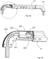
- Figures 3a to 4b illustrate in detail both the transformation means 22 and the transmission means 23, illustrating, respectively, the non-rotated and rotated condition of the handle part 21.
- the entire telescopic handle is locked, i.e. it stably fixes, in an extracted or inserted condition, the lateral elongated elements 30 (reference to figure 1 ), while the rotated condition of the handle part 21 causes the unlocking of the hooking means placed in the lateral elongated elements 30 and allows the transition from the inserted condition to the extracted condition or vice versa.
- the transformation means 22 comprise a first part 221 positioned adjacent to and in contact with one end of the handle part 21 and a second part 222 in contact with said first part 221.
- the second part 222 is mounted translatable with respect to the first part 221, such that the second part 222 moves from an approached condition to a spaced apart condition with respect to the first part 221.
- Figures 3a and 3b illustrate the approached condition of the second part 222, the handle part 21 is in a non-rotated condition and the second part 222 is moved to the right, in contact with the first part 221.
- the second part 222 is in a spaced apart condition: the handle part 21 is rotated and the second part 222 is moved to the left, no longer in contact with the first part 221.
- the displacement of the second part 222 occurs thanks to the presence of a pusher element 224.
- the two parts 221 and 222 identify a housing seat 220 for such a pusher element, particularly a compartment suitable to enclose the pusher element 224.
- the pusher element 224 in the condition illustrated in figure 3b , is located with its external walls in contact with the internal walls of such housing seat.
- a rotation of the handle part 21 also causes rotation of the pusher element 224 and the contact of the walls causes the pusher element 224 to push the second part 222 to the left, figure 4b .
- the second part 222 has an output element 223 which transmits the displacement to the transmission means 23.
- FIG. 3a to 4b illustrate a preferred embodiment of the transmission means 23.
- the lateral parts 24 have a curvilinear element with a channel 231 that provides a course corresponding to the profile of said curvilinear element.
- the transmission of the translation motion of the element 223 takes place thanks to the presence of a plurality of spheres 232 inserted inside the channel 231 and arranged adjacent to each other.
- the sphere 232 closest to the central elongated element i.e. the one more to the right with reference to the figures, is connected to the second part 222.
- the element 223 has dimensions equal to those of the channel 231, so that it can fit inside the channel 231, in a rotated condition of the handle part 21 ( figure 4b ), and push the spheres 232.
- the element 223 may be independent of the spheres 232.
- the element 223 is firmly connected to the plurality of spheres 232, whereby, by rotating the handle part 21, it pushes the spheres 232 downwards, while by returning the handle part 21 in a non-rotated condition, it drags the spheres 232 to the right.
- Such configuration allows not to provide elastic means that keep the hooking pins in a predetermined position, but allows to always control the movement of the hooking pins, ensuring that the pins are active in a non-rotated condition of the handle part 21 and that they are deactivated in a rotated condition of the handle part 21.
- means may be provided for bringing the second part 222 in approaching condition with respect to the first part 221.
- such means may consist of connecting means between the pusher element 224 and the second part 222 so that the second part 222 is not only pushed by the pusher element 224 to the left, with reference to the figures, but is also pulled to the right, with reference to the figures, when the handle part 21 returns to the non-rotated condition.
- elastic elements such as springs or the like, positioned between the second part 222 and the curvilinear element 24 which are compressed in a rotated condition of the handle part 21 can be provided.
- Figure 5 illustrates an exploded view of the handle object of the present invention and in particular a preferred embodiment of the pusher element 224.
- the pusher element 224 consists of a pin 2241 having two protruding heads 2242.
- the first part 221 and the second part 222 have insertion seats of the pin 2241 ends.
- the first part 221 has a first face 2211 facing in the direction of a second face 2221 belonging to the second part 222.
- Faces 2211 and 2221 have a profile complementary to the shape of the protruding heads 2242, such that, in an approached condition, the two faces 2211 and 2221 make a housing seat 220 ( fig. 3b ) of the protruding heads 2242, whose surfaces are in contact with said heads 2242.
- the pin 2241 is then inserted with its ends into the first and second parts and is free to rotate integrally with the handle part 21.
- the pin 2241 during rotation drags the protruding heads 2242, which slide along the profile of the surfaces 2211 and 2221 in such a way that during rotation of said handle part 21, the heads 2242 push the second part 222 in a spaced apart condition.
- the protruding heads 2242 consist of wheels which have a rotation axis perpendicular to the longitudinal axis of the pin 2241.
- the handle part 21 in a non-rotated condition, has at least one upper external wall made so as to be flush with the upper external wall of the remaining part of the central elongated element 20.
- the handle part 21 is on three sides, apart from the lower side with the face 210, flush with the external walls of the central elongated element 20.
Landscapes
- Purses, Travelling Bags, Baskets, Or Suitcases (AREA)
Claims (7)
- Teleskopgriff für transportable Behälter, wie Koffer, Trolley-Koffer oder dergleichen, der ein oberes zentrales längliches Element (20) und zwei seitliche längliche Elemente (30), die mit dem zentralen länglichen Element (20) verbunden sind, umfasst, wobei sich die seitlichen länglichen Elemente (30) von einem ausgezogenen Zustand in einen Zustand, der in spezielle Sitze eingesetzt ist,die im Inneren des Behälters bereitgestellt sind, bewegt,
sich das zentrale längliche Element (20) von einem maximal beabstandeten Zustand, der dem ausgezogenen Zustand entspricht, zu einem maximal annähernden Zustand, der dem eingesetzten Zustand entspricht,in Bezug auf den Behälter bewegt,wobei Mittel zum Einhaken mindestens eines seitlichen länglichen Elements (30), das dazu konfiguriert ist, den ausgezogenen Zustand oder den eingesetzten Zustand stabil zu halten, vorhanden sind,und Mittel zum Aktivieren/Deaktivieren der Einhakmittel vorhanden sind,wobei die Aktivierungs-/Deaktivierungsmittel aus einem Griffteil (21) bestehen, das zu dem zentralen länglichen Element (20) gehört,wobei das Griffteil (21) in Bezug auf die Längsachse des zentralen länglichen Elements (20) schwenkbar montiert und dazu konfiguriert ist, dass die Drehung des Griffteils (21) bewirkt, dass das Einhakmittel aktiviert/deaktiviert wird, wobei das zentrale längliche Element (20) Mittel (22) zum Umwandeln der Drehbewegung des Griffteils (21) umfasst, wobei die Mittel (22) dazu konfiguriert sind, die Drehung des Griffteils (21) in eine Verschiebungsbewegung umzuwandeln, wobei Übertragungsmittel (23) der Verschiebungsbewegung an den Einhakmitteln bereitgestellt sind,wobei:die Umwandlungsmittel (22) mindestens ein erstes Teil (221), das angrenzend an und in Kontakt mit einem Ende des Griffteils (21) positioniert ist, und ein zweites Teil (222) in Kontakt mit dem ersten Teil (221) umfassen, wobei das zweite Teil (222) in Bezug auf das erste Teil (221) verschiebbar derart montiert ist, dass sich das zweite Teil (222) von einem angenäherten Zustand zu einem beabstandeten Zustand in Bezug auf das erste Teil (221) bewegt,in einem angenäherten Zustand das erste Teil (221) und das zweite Teil (222) einen Gehäusesitz (220) identifizieren, der ein Schubelement (224) aufnimmt, das mit dem Griffteil (21) derart einstückig ist, dass während der Drehung des Griffteils (21) die Außenwände des Schubelements (224) das zweite Teil (222) schieben, das wiederum die Verschiebung an die Übertragungsmittel (23) überträgt, dadurch gekennzeichnet, dassdas Schubelement (224) aus einem Stift (2241) besteht, der mindestens einen vorragenden Kopf (2242) aufweist,das erste (221) und das zweite (222) Teil Einsetzsitze für die Enden des Stifts (2241) aufweisen,wobei das erste Teil (221) eine erste Fläche (2211) aufweist, die in die Richtung einer zweiten Fläche (2221) gewandt ist, die zu dem zweiten Teil (222) gehört, wobei die erste (2211) und die zweite (2221) Fläche ein Profil aufweisen, das zu der Form des vorragenden Kopfes (2242) derart komplementär ist, dass in einem angenäherten Zustand die zwei Flächen (2211, 2221) einen Gehäusesitz (220) des vorragenden Kopfes (2242) identifizieren, und derart, dass während der Drehung des Griffteils (21) der vorragende Kopf (2242) entlang des Profils der Flächen (2211, 2221) läuft und das zweite Teil (222) zu einem beabstandeten Zustand schiebt. - Griff nach Anspruch 1, bei dem der vorragende Kopf (2242) aus einem Rad besteht, das eine Drehachse senkrecht zu der Längsachse des Stifts (2241) aufweist.
- Griff nach einem oder mehreren der vorstehenden Ansprüche, wobei der Stift (2241) zwei vorragende Köpfe (2242) aufweist, die dem Abschnitt des Stifts (2241) diametral entgegengesetzt positioniert sind.
- Griff nach einem oder mehreren der vorstehenden Ansprüche, wobei mindestens ein Ende des zentralen länglichen Elements (20) mit dem entsprechenden seitlichen länglichen Element (30) durch ein krummliniges Element verbunden ist, wobei das krummlinige Element einen Kanal (231) aufweist, der einen Verlauf bereitstellt, der dem Profil des krummlinigen Elements entspricht, wobei die Übertragungsmittel eine Vielzahl von Kugeln (232) umfassen, die in den Kanal (231) eingesetzt und aneinander angrenzend eingerichtet sind, wobei die Kugel nahe dem zentralen länglichen Element (20) mit dem zweiten Teil (222) in Verbindung steht.
- Griff nach einem oder mehreren der vorstehenden Ansprüche, wobei die Umwandlungsmittel (22) an beiden Enden des zentralen länglichen Elements (20) positioniert bereitgestellt sind.
- Griff nach einem oder mehreren der vorstehenden Ansprüche, wobei das Griffteil (21) mindestens eine obere Außenwand aufweist, die derart hergestellt ist, dass sie mit der oberen Außenwand des verbleibenden Teils (24) des zentralen länglichen Elements (20) in einem nicht gedrehten Zustand des Griffteils (21) bündig ist.
- Transportabler Behälter vom Typ Trolley-Koffer, Koffer oder dergleichen, dadurch gekennzeichnet, dass er einen Griff umfasst, der nach einem oder mehreren der Ansprüche 1 bis 6 hergestellt ist.
Applications Claiming Priority (2)
| Application Number | Priority Date | Filing Date | Title |
|---|---|---|---|
| IT102019000006669A IT201900006669A1 (it) | 2019-05-10 | 2019-05-10 | Maniglia telescopica per contenitori trasportabili, quali valigie, trolley o simili |
| PCT/IB2020/054193 WO2020229936A1 (en) | 2019-05-10 | 2020-05-04 | Telescopic handle |
Publications (2)
| Publication Number | Publication Date |
|---|---|
| EP3965609A1 EP3965609A1 (de) | 2022-03-16 |
| EP3965609B1 true EP3965609B1 (de) | 2023-02-01 |
Family
ID=68072933
Family Applications (1)
| Application Number | Title | Priority Date | Filing Date |
|---|---|---|---|
| EP20742444.1A Active EP3965609B1 (de) | 2019-05-10 | 2020-05-04 | Teleskopgriff |
Country Status (7)
| Country | Link |
|---|---|
| US (1) | US20220202153A1 (de) |
| EP (1) | EP3965609B1 (de) |
| JP (1) | JP2022531677A (de) |
| KR (1) | KR20220007071A (de) |
| CN (1) | CN114040690A (de) |
| IT (1) | IT201900006669A1 (de) |
| WO (1) | WO2020229936A1 (de) |
Families Citing this family (2)
| Publication number | Priority date | Publication date | Assignee | Title |
|---|---|---|---|---|
| KR102831387B1 (ko) * | 2023-01-10 | 2025-07-07 | 학교법인 건국대학교 | 이동형 방사선 차폐막 장치 |
| US20240398082A1 (en) * | 2024-06-21 | 2024-12-05 | Reginald Keith Sapp | Wheel Luggage with Telegraphing Handle |
Family Cites Families (10)
| Publication number | Priority date | Publication date | Assignee | Title |
|---|---|---|---|---|
| US5371923A (en) * | 1993-08-04 | 1994-12-13 | Chang; Fu J. | Handle for a baggage cart |
| US5553350A (en) * | 1994-10-12 | 1996-09-10 | Chang; Fu-Jung | Telescopic handle with freely adjustable length |
| US5970579A (en) * | 1998-05-19 | 1999-10-26 | Ting Cheng Co., Ltd. | Handle assembly for a wheeled luggage case |
| EP1458257A2 (de) * | 2001-12-21 | 2004-09-22 | Delsey Benelux N.V. | Schwenkbarer ausziehbarer griff |
| US6874604B2 (en) * | 2002-10-23 | 2005-04-05 | Travelpro International, Inc. | Adjustable luggage handle system with locking pin |
| US7658269B2 (en) * | 2006-02-13 | 2010-02-09 | Chen-Chuan Wu | Handle of a two pulling rod suitcase |
| CN201088233Y (zh) * | 2007-07-03 | 2008-07-23 | 罗桐新 | 一种箱包拉杆的旋转握把 |
| US7802665B2 (en) * | 2007-09-28 | 2010-09-28 | Joy Tong | Rotation-controllable rotary grip assembly for luggage handle |
| US20160150862A1 (en) * | 2013-06-28 | 2016-06-02 | G.T. Line S.R.L. | Transportable container and related handle |
| EP3318158A1 (de) * | 2016-11-07 | 2018-05-09 | Samsonite IP Holdings S.à.r.l. | Ausziehbarer nachziehgriff für ein gepäckstück |
-
2019
- 2019-05-10 IT IT102019000006669A patent/IT201900006669A1/it unknown
-
2020
- 2020-05-04 EP EP20742444.1A patent/EP3965609B1/de active Active
- 2020-05-04 CN CN202080048425.3A patent/CN114040690A/zh active Pending
- 2020-05-04 US US17/608,583 patent/US20220202153A1/en not_active Abandoned
- 2020-05-04 KR KR1020217037663A patent/KR20220007071A/ko not_active Withdrawn
- 2020-05-04 JP JP2021565771A patent/JP2022531677A/ja active Pending
- 2020-05-04 WO PCT/IB2020/054193 patent/WO2020229936A1/en not_active Ceased
Also Published As
| Publication number | Publication date |
|---|---|
| KR20220007071A (ko) | 2022-01-18 |
| CN114040690A (zh) | 2022-02-11 |
| WO2020229936A1 (en) | 2020-11-19 |
| IT201900006669A1 (it) | 2020-11-10 |
| EP3965609A1 (de) | 2022-03-16 |
| JP2022531677A (ja) | 2022-07-08 |
| US20220202153A1 (en) | 2022-06-30 |
Similar Documents
| Publication | Publication Date | Title |
|---|---|---|
| US10286940B2 (en) | Child stroller apparatus | |
| US6301746B1 (en) | Telescoping handle assembly for luggage and other luggable items | |
| EP3998184B1 (de) | Kinderwagenvorrichtung | |
| US10286941B2 (en) | Infant stroller apparatus | |
| US11993302B2 (en) | Wheeled carrying apparatus | |
| US20030038007A1 (en) | Telescopic handle for luggage cart | |
| KR20180071313A (ko) | 차량용 도어 손잡이 | |
| US9629429B2 (en) | Retractable wheel mechanism | |
| US20020167143A1 (en) | Folding structure for kick scooter | |
| US20020014382A1 (en) | Combination carrying handle and retractable handle | |
| EP1059859A1 (de) | Verbesserungen für gepäck mit laufrollen | |
| WO2016073902A1 (en) | Rolling luggage with multiple modes of conveyance | |
| US20220202153A1 (en) | Telescopic handle | |
| GB2280707A (en) | A latching telescopic handle for a baggage cart | |
| US6877760B2 (en) | Foldable stroller | |
| JP5394611B2 (ja) | 回動自在な引き具構造体 | |
| CN112603007A (zh) | 操作手柄装置 | |
| US20240124043A1 (en) | Wheeled carrying apparatus | |
| CN209008651U (zh) | 一种推挂车 | |
| CN220275108U (zh) | 具有把手功能与拉杆功能的提拉组件及行李箱 | |
| JP4505453B2 (ja) | 牽引可能な鞄用の選択的回転可能ハンドル組立体 | |
| WO2000021817A1 (en) | Improvements in and relating to foldable wheeled trolleys | |
| ES2881308T3 (es) | Conjunto de gancho con pestillo y mecanismo de gatillo | |
| WO1999044461A1 (en) | Improvements in wheeled luggage and associated devices | |
| CN120440104A (zh) | 滑动推车车架及推车 |
Legal Events
| Date | Code | Title | Description |
|---|---|---|---|
| STAA | Information on the status of an ep patent application or granted ep patent |
Free format text: STATUS: UNKNOWN |
|
| STAA | Information on the status of an ep patent application or granted ep patent |
Free format text: STATUS: THE INTERNATIONAL PUBLICATION HAS BEEN MADE |
|
| PUAI | Public reference made under article 153(3) epc to a published international application that has entered the european phase |
Free format text: ORIGINAL CODE: 0009012 |
|
| STAA | Information on the status of an ep patent application or granted ep patent |
Free format text: STATUS: REQUEST FOR EXAMINATION WAS MADE |
|
| 17P | Request for examination filed |
Effective date: 20211123 |
|
| AK | Designated contracting states |
Kind code of ref document: A1 Designated state(s): AL AT BE BG CH CY CZ DE DK EE ES FI FR GB GR HR HU IE IS IT LI LT LU LV MC MK MT NL NO PL PT RO RS SE SI SK SM TR |
|
| RIN1 | Information on inventor provided before grant (corrected) |
Inventor name: BONINSEGNI, ALESSIO |
|
| DAV | Request for validation of the european patent (deleted) | ||
| DAX | Request for extension of the european patent (deleted) | ||
| GRAP | Despatch of communication of intention to grant a patent |
Free format text: ORIGINAL CODE: EPIDOSNIGR1 |
|
| STAA | Information on the status of an ep patent application or granted ep patent |
Free format text: STATUS: GRANT OF PATENT IS INTENDED |
|
| INTG | Intention to grant announced |
Effective date: 20221024 |
|
| GRAS | Grant fee paid |
Free format text: ORIGINAL CODE: EPIDOSNIGR3 |
|
| GRAA | (expected) grant |
Free format text: ORIGINAL CODE: 0009210 |
|
| STAA | Information on the status of an ep patent application or granted ep patent |
Free format text: STATUS: THE PATENT HAS BEEN GRANTED |
|
| AK | Designated contracting states |
Kind code of ref document: B1 Designated state(s): AL AT BE BG CH CY CZ DE DK EE ES FI FR GB GR HR HU IE IS IT LI LT LU LV MC MK MT NL NO PL PT RO RS SE SI SK SM TR |
|
| REG | Reference to a national code |
Ref country code: GB Ref legal event code: FG4D |
|
| REG | Reference to a national code |
Ref country code: CH Ref legal event code: EP Ref country code: AT Ref legal event code: REF Ref document number: 1546705 Country of ref document: AT Kind code of ref document: T Effective date: 20230215 |
|
| REG | Reference to a national code |
Ref country code: DE Ref legal event code: R096 Ref document number: 602020007948 Country of ref document: DE |
|
| REG | Reference to a national code |
Ref country code: IE Ref legal event code: FG4D |
|
| REG | Reference to a national code |
Ref country code: NL Ref legal event code: FP |
|
| REG | Reference to a national code |
Ref country code: LT Ref legal event code: MG9D |
|
| REG | Reference to a national code |
Ref country code: AT Ref legal event code: MK05 Ref document number: 1546705 Country of ref document: AT Kind code of ref document: T Effective date: 20230201 |
|
| PG25 | Lapsed in a contracting state [announced via postgrant information from national office to epo] |
Ref country code: RS Free format text: LAPSE BECAUSE OF FAILURE TO SUBMIT A TRANSLATION OF THE DESCRIPTION OR TO PAY THE FEE WITHIN THE PRESCRIBED TIME-LIMIT Effective date: 20230201 Ref country code: PT Free format text: LAPSE BECAUSE OF FAILURE TO SUBMIT A TRANSLATION OF THE DESCRIPTION OR TO PAY THE FEE WITHIN THE PRESCRIBED TIME-LIMIT Effective date: 20230601 Ref country code: NO Free format text: LAPSE BECAUSE OF FAILURE TO SUBMIT A TRANSLATION OF THE DESCRIPTION OR TO PAY THE FEE WITHIN THE PRESCRIBED TIME-LIMIT Effective date: 20230501 Ref country code: LV Free format text: LAPSE BECAUSE OF FAILURE TO SUBMIT A TRANSLATION OF THE DESCRIPTION OR TO PAY THE FEE WITHIN THE PRESCRIBED TIME-LIMIT Effective date: 20230201 Ref country code: LT Free format text: LAPSE BECAUSE OF FAILURE TO SUBMIT A TRANSLATION OF THE DESCRIPTION OR TO PAY THE FEE WITHIN THE PRESCRIBED TIME-LIMIT Effective date: 20230201 Ref country code: HR Free format text: LAPSE BECAUSE OF FAILURE TO SUBMIT A TRANSLATION OF THE DESCRIPTION OR TO PAY THE FEE WITHIN THE PRESCRIBED TIME-LIMIT Effective date: 20230201 Ref country code: ES Free format text: LAPSE BECAUSE OF FAILURE TO SUBMIT A TRANSLATION OF THE DESCRIPTION OR TO PAY THE FEE WITHIN THE PRESCRIBED TIME-LIMIT Effective date: 20230201 Ref country code: AT Free format text: LAPSE BECAUSE OF FAILURE TO SUBMIT A TRANSLATION OF THE DESCRIPTION OR TO PAY THE FEE WITHIN THE PRESCRIBED TIME-LIMIT Effective date: 20230201 |
|
| PG25 | Lapsed in a contracting state [announced via postgrant information from national office to epo] |
Ref country code: SE Free format text: LAPSE BECAUSE OF FAILURE TO SUBMIT A TRANSLATION OF THE DESCRIPTION OR TO PAY THE FEE WITHIN THE PRESCRIBED TIME-LIMIT Effective date: 20230201 Ref country code: PL Free format text: LAPSE BECAUSE OF FAILURE TO SUBMIT A TRANSLATION OF THE DESCRIPTION OR TO PAY THE FEE WITHIN THE PRESCRIBED TIME-LIMIT Effective date: 20230201 Ref country code: IS Free format text: LAPSE BECAUSE OF FAILURE TO SUBMIT A TRANSLATION OF THE DESCRIPTION OR TO PAY THE FEE WITHIN THE PRESCRIBED TIME-LIMIT Effective date: 20230601 Ref country code: GR Free format text: LAPSE BECAUSE OF FAILURE TO SUBMIT A TRANSLATION OF THE DESCRIPTION OR TO PAY THE FEE WITHIN THE PRESCRIBED TIME-LIMIT Effective date: 20230502 Ref country code: FI Free format text: LAPSE BECAUSE OF FAILURE TO SUBMIT A TRANSLATION OF THE DESCRIPTION OR TO PAY THE FEE WITHIN THE PRESCRIBED TIME-LIMIT Effective date: 20230201 |
|
| PG25 | Lapsed in a contracting state [announced via postgrant information from national office to epo] |
Ref country code: SM Free format text: LAPSE BECAUSE OF FAILURE TO SUBMIT A TRANSLATION OF THE DESCRIPTION OR TO PAY THE FEE WITHIN THE PRESCRIBED TIME-LIMIT Effective date: 20230201 Ref country code: RO Free format text: LAPSE BECAUSE OF FAILURE TO SUBMIT A TRANSLATION OF THE DESCRIPTION OR TO PAY THE FEE WITHIN THE PRESCRIBED TIME-LIMIT Effective date: 20230201 Ref country code: EE Free format text: LAPSE BECAUSE OF FAILURE TO SUBMIT A TRANSLATION OF THE DESCRIPTION OR TO PAY THE FEE WITHIN THE PRESCRIBED TIME-LIMIT Effective date: 20230201 Ref country code: DK Free format text: LAPSE BECAUSE OF FAILURE TO SUBMIT A TRANSLATION OF THE DESCRIPTION OR TO PAY THE FEE WITHIN THE PRESCRIBED TIME-LIMIT Effective date: 20230201 Ref country code: CZ Free format text: LAPSE BECAUSE OF FAILURE TO SUBMIT A TRANSLATION OF THE DESCRIPTION OR TO PAY THE FEE WITHIN THE PRESCRIBED TIME-LIMIT Effective date: 20230201 |
|
| REG | Reference to a national code |
Ref country code: DE Ref legal event code: R097 Ref document number: 602020007948 Country of ref document: DE |
|
| PG25 | Lapsed in a contracting state [announced via postgrant information from national office to epo] |
Ref country code: SK Free format text: LAPSE BECAUSE OF FAILURE TO SUBMIT A TRANSLATION OF THE DESCRIPTION OR TO PAY THE FEE WITHIN THE PRESCRIBED TIME-LIMIT Effective date: 20230201 |
|
| PLBE | No opposition filed within time limit |
Free format text: ORIGINAL CODE: 0009261 |
|
| STAA | Information on the status of an ep patent application or granted ep patent |
Free format text: STATUS: NO OPPOSITION FILED WITHIN TIME LIMIT |
|
| 26N | No opposition filed |
Effective date: 20231103 |
|
| PG25 | Lapsed in a contracting state [announced via postgrant information from national office to epo] |
Ref country code: MC Free format text: LAPSE BECAUSE OF FAILURE TO SUBMIT A TRANSLATION OF THE DESCRIPTION OR TO PAY THE FEE WITHIN THE PRESCRIBED TIME-LIMIT Effective date: 20230201 |
|
| REG | Reference to a national code |
Ref country code: BE Ref legal event code: MM Effective date: 20230531 |
|
| PG25 | Lapsed in a contracting state [announced via postgrant information from national office to epo] |
Ref country code: SI Free format text: LAPSE BECAUSE OF FAILURE TO SUBMIT A TRANSLATION OF THE DESCRIPTION OR TO PAY THE FEE WITHIN THE PRESCRIBED TIME-LIMIT Effective date: 20230201 Ref country code: MC Free format text: LAPSE BECAUSE OF FAILURE TO SUBMIT A TRANSLATION OF THE DESCRIPTION OR TO PAY THE FEE WITHIN THE PRESCRIBED TIME-LIMIT Effective date: 20230201 Ref country code: LU Free format text: LAPSE BECAUSE OF NON-PAYMENT OF DUE FEES Effective date: 20230504 |
|
| REG | Reference to a national code |
Ref country code: IE Ref legal event code: MM4A |
|
| PG25 | Lapsed in a contracting state [announced via postgrant information from national office to epo] |
Ref country code: IE Free format text: LAPSE BECAUSE OF NON-PAYMENT OF DUE FEES Effective date: 20230504 |
|
| PG25 | Lapsed in a contracting state [announced via postgrant information from national office to epo] |
Ref country code: IE Free format text: LAPSE BECAUSE OF NON-PAYMENT OF DUE FEES Effective date: 20230504 |
|
| PG25 | Lapsed in a contracting state [announced via postgrant information from national office to epo] |
Ref country code: IT Free format text: LAPSE BECAUSE OF FAILURE TO SUBMIT A TRANSLATION OF THE DESCRIPTION OR TO PAY THE FEE WITHIN THE PRESCRIBED TIME-LIMIT Effective date: 20230201 Ref country code: BE Free format text: LAPSE BECAUSE OF NON-PAYMENT OF DUE FEES Effective date: 20230531 |
|
| PG25 | Lapsed in a contracting state [announced via postgrant information from national office to epo] |
Ref country code: BG Free format text: LAPSE BECAUSE OF FAILURE TO SUBMIT A TRANSLATION OF THE DESCRIPTION OR TO PAY THE FEE WITHIN THE PRESCRIBED TIME-LIMIT Effective date: 20230201 |
|
| PG25 | Lapsed in a contracting state [announced via postgrant information from national office to epo] |
Ref country code: BG Free format text: LAPSE BECAUSE OF FAILURE TO SUBMIT A TRANSLATION OF THE DESCRIPTION OR TO PAY THE FEE WITHIN THE PRESCRIBED TIME-LIMIT Effective date: 20230201 |
|
| PGFP | Annual fee paid to national office [announced via postgrant information from national office to epo] |
Ref country code: NL Payment date: 20250526 Year of fee payment: 6 |
|
| PGFP | Annual fee paid to national office [announced via postgrant information from national office to epo] |
Ref country code: DE Payment date: 20250529 Year of fee payment: 6 |
|
| PGFP | Annual fee paid to national office [announced via postgrant information from national office to epo] |
Ref country code: GB Payment date: 20250527 Year of fee payment: 6 |
|
| PGFP | Annual fee paid to national office [announced via postgrant information from national office to epo] |
Ref country code: FR Payment date: 20250526 Year of fee payment: 6 |
|
| PGFP | Annual fee paid to national office [announced via postgrant information from national office to epo] |
Ref country code: CH Payment date: 20250601 Year of fee payment: 6 |
|
| PG25 | Lapsed in a contracting state [announced via postgrant information from national office to epo] |
Ref country code: CY Free format text: LAPSE BECAUSE OF FAILURE TO SUBMIT A TRANSLATION OF THE DESCRIPTION OR TO PAY THE FEE WITHIN THE PRESCRIBED TIME-LIMIT; INVALID AB INITIO Effective date: 20200504 |
|
| PG25 | Lapsed in a contracting state [announced via postgrant information from national office to epo] |
Ref country code: HU Free format text: LAPSE BECAUSE OF FAILURE TO SUBMIT A TRANSLATION OF THE DESCRIPTION OR TO PAY THE FEE WITHIN THE PRESCRIBED TIME-LIMIT; INVALID AB INITIO Effective date: 20200504 |
|
| PG25 | Lapsed in a contracting state [announced via postgrant information from national office to epo] |
Ref country code: TR Free format text: LAPSE BECAUSE OF FAILURE TO SUBMIT A TRANSLATION OF THE DESCRIPTION OR TO PAY THE FEE WITHIN THE PRESCRIBED TIME-LIMIT Effective date: 20230201 |