EP3965528A1 - Tête d'impression pour une imprimante tridimensionnelle - Google Patents
Tête d'impression pour une imprimante tridimensionnelle Download PDFInfo
- Publication number
- EP3965528A1 EP3965528A1 EP21195326.0A EP21195326A EP3965528A1 EP 3965528 A1 EP3965528 A1 EP 3965528A1 EP 21195326 A EP21195326 A EP 21195326A EP 3965528 A1 EP3965528 A1 EP 3965528A1
- Authority
- EP
- European Patent Office
- Prior art keywords
- tube
- heating
- heating layer
- printhead according
- layer
- Prior art date
- Legal status (The legal status is an assumption and is not a legal conclusion. Google has not performed a legal analysis and makes no representation as to the accuracy of the status listed.)
- Pending
Links
- 238000010438 heat treatment Methods 0.000 claims abstract description 81
- 239000000463 material Substances 0.000 claims abstract description 12
- 238000007639 printing Methods 0.000 claims abstract description 10
- 238000005507 spraying Methods 0.000 claims abstract description 4
- 230000008021 deposition Effects 0.000 claims abstract 2
- 238000000151 deposition Methods 0.000 claims abstract 2
- 230000008018 melting Effects 0.000 claims abstract 2
- 238000002844 melting Methods 0.000 claims abstract 2
- 229910052751 metal Inorganic materials 0.000 claims description 18
- 239000002184 metal Substances 0.000 claims description 18
- 239000000919 ceramic Substances 0.000 claims description 6
- 238000005485 electric heating Methods 0.000 abstract 1
- 238000011161 development Methods 0.000 description 7
- 230000018109 developmental process Effects 0.000 description 7
- 238000001816 cooling Methods 0.000 description 4
- RYGMFSIKBFXOCR-UHFFFAOYSA-N Copper Chemical compound [Cu] RYGMFSIKBFXOCR-UHFFFAOYSA-N 0.000 description 3
- 229910052802 copper Inorganic materials 0.000 description 3
- 239000010949 copper Substances 0.000 description 3
- 230000001419 dependent effect Effects 0.000 description 3
- 238000004519 manufacturing process Methods 0.000 description 3
- 238000000034 method Methods 0.000 description 3
- 229910001369 Brass Inorganic materials 0.000 description 2
- 229910000906 Bronze Inorganic materials 0.000 description 2
- OKTJSMMVPCPJKN-UHFFFAOYSA-N Carbon Chemical compound [C] OKTJSMMVPCPJKN-UHFFFAOYSA-N 0.000 description 2
- PXHVJJICTQNCMI-UHFFFAOYSA-N Nickel Chemical compound [Ni] PXHVJJICTQNCMI-UHFFFAOYSA-N 0.000 description 2
- 229910045601 alloy Inorganic materials 0.000 description 2
- 239000000956 alloy Substances 0.000 description 2
- 239000010951 brass Substances 0.000 description 2
- 239000010974 bronze Substances 0.000 description 2
- KUNSUQLRTQLHQQ-UHFFFAOYSA-N copper tin Chemical compound [Cu].[Sn] KUNSUQLRTQLHQQ-UHFFFAOYSA-N 0.000 description 2
- 239000012777 electrically insulating material Substances 0.000 description 2
- 239000010408 film Substances 0.000 description 2
- 239000007788 liquid Substances 0.000 description 2
- WOCIAKWEIIZHES-UHFFFAOYSA-N ruthenium(iv) oxide Chemical compound O=[Ru]=O WOCIAKWEIIZHES-UHFFFAOYSA-N 0.000 description 2
- 239000010409 thin film Substances 0.000 description 2
- 238000011144 upstream manufacturing Methods 0.000 description 2
- 238000010146 3D printing Methods 0.000 description 1
- VYZAMTAEIAYCRO-UHFFFAOYSA-N Chromium Chemical compound [Cr] VYZAMTAEIAYCRO-UHFFFAOYSA-N 0.000 description 1
- 244000089486 Phragmites australis subsp australis Species 0.000 description 1
- 229910000831 Steel Inorganic materials 0.000 description 1
- 229910052782 aluminium Inorganic materials 0.000 description 1
- XAGFODPZIPBFFR-UHFFFAOYSA-N aluminium Chemical compound [Al] XAGFODPZIPBFFR-UHFFFAOYSA-N 0.000 description 1
- 238000009529 body temperature measurement Methods 0.000 description 1
- 239000002041 carbon nanotube Substances 0.000 description 1
- 229910021393 carbon nanotube Inorganic materials 0.000 description 1
- 229910052804 chromium Inorganic materials 0.000 description 1
- 239000011651 chromium Substances 0.000 description 1
- 239000004020 conductor Substances 0.000 description 1
- 239000002826 coolant Substances 0.000 description 1
- 238000009826 distribution Methods 0.000 description 1
- 230000007613 environmental effect Effects 0.000 description 1
- 229910002804 graphite Inorganic materials 0.000 description 1
- 239000010439 graphite Substances 0.000 description 1
- 238000009413 insulation Methods 0.000 description 1
- 238000005259 measurement Methods 0.000 description 1
- 229910052759 nickel Inorganic materials 0.000 description 1
- 239000000615 nonconductor Substances 0.000 description 1
- TWNQGVIAIRXVLR-UHFFFAOYSA-N oxo(oxoalumanyloxy)alumane Chemical compound O=[Al]O[Al]=O TWNQGVIAIRXVLR-UHFFFAOYSA-N 0.000 description 1
- 239000003973 paint Substances 0.000 description 1
- KDLHZDBZIXYQEI-UHFFFAOYSA-N palladium Substances [Pd] KDLHZDBZIXYQEI-UHFFFAOYSA-N 0.000 description 1
- 230000001105 regulatory effect Effects 0.000 description 1
- 238000004544 sputter deposition Methods 0.000 description 1
- 239000010935 stainless steel Substances 0.000 description 1
- 229910001220 stainless steel Inorganic materials 0.000 description 1
- 239000010959 steel Substances 0.000 description 1
- 238000007740 vapor deposition Methods 0.000 description 1
- 238000012800 visualization Methods 0.000 description 1
- 238000004804 winding Methods 0.000 description 1
Images


Classifications
-
- H—ELECTRICITY
- H05—ELECTRIC TECHNIQUES NOT OTHERWISE PROVIDED FOR
- H05B—ELECTRIC HEATING; ELECTRIC LIGHT SOURCES NOT OTHERWISE PROVIDED FOR; CIRCUIT ARRANGEMENTS FOR ELECTRIC LIGHT SOURCES, IN GENERAL
- H05B1/00—Details of electric heating devices
- H05B1/02—Automatic switching arrangements specially adapted to apparatus ; Control of heating devices
- H05B1/0227—Applications
- H05B1/023—Industrial applications
- H05B1/0244—Heating of fluids
-
- B—PERFORMING OPERATIONS; TRANSPORTING
- B29—WORKING OF PLASTICS; WORKING OF SUBSTANCES IN A PLASTIC STATE IN GENERAL
- B29C—SHAPING OR JOINING OF PLASTICS; SHAPING OF MATERIAL IN A PLASTIC STATE, NOT OTHERWISE PROVIDED FOR; AFTER-TREATMENT OF THE SHAPED PRODUCTS, e.g. REPAIRING
- B29C64/00—Additive manufacturing, i.e. manufacturing of three-dimensional [3D] objects by additive deposition, additive agglomeration or additive layering, e.g. by 3D printing, stereolithography or selective laser sintering
- B29C64/20—Apparatus for additive manufacturing; Details thereof or accessories therefor
- B29C64/205—Means for applying layers
- B29C64/209—Heads; Nozzles
-
- B—PERFORMING OPERATIONS; TRANSPORTING
- B29—WORKING OF PLASTICS; WORKING OF SUBSTANCES IN A PLASTIC STATE IN GENERAL
- B29C—SHAPING OR JOINING OF PLASTICS; SHAPING OF MATERIAL IN A PLASTIC STATE, NOT OTHERWISE PROVIDED FOR; AFTER-TREATMENT OF THE SHAPED PRODUCTS, e.g. REPAIRING
- B29C64/00—Additive manufacturing, i.e. manufacturing of three-dimensional [3D] objects by additive deposition, additive agglomeration or additive layering, e.g. by 3D printing, stereolithography or selective laser sintering
- B29C64/20—Apparatus for additive manufacturing; Details thereof or accessories therefor
- B29C64/295—Heating elements
-
- B—PERFORMING OPERATIONS; TRANSPORTING
- B33—ADDITIVE MANUFACTURING TECHNOLOGY
- B33Y—ADDITIVE MANUFACTURING, i.e. MANUFACTURING OF THREE-DIMENSIONAL [3-D] OBJECTS BY ADDITIVE DEPOSITION, ADDITIVE AGGLOMERATION OR ADDITIVE LAYERING, e.g. BY 3-D PRINTING, STEREOLITHOGRAPHY OR SELECTIVE LASER SINTERING
- B33Y30/00—Apparatus for additive manufacturing; Details thereof or accessories therefor
-
- H—ELECTRICITY
- H05—ELECTRIC TECHNIQUES NOT OTHERWISE PROVIDED FOR
- H05B—ELECTRIC HEATING; ELECTRIC LIGHT SOURCES NOT OTHERWISE PROVIDED FOR; CIRCUIT ARRANGEMENTS FOR ELECTRIC LIGHT SOURCES, IN GENERAL
- H05B3/00—Ohmic-resistance heating
- H05B3/40—Heating elements having the shape of rods or tubes
- H05B3/42—Heating elements having the shape of rods or tubes non-flexible
-
- H—ELECTRICITY
- H05—ELECTRIC TECHNIQUES NOT OTHERWISE PROVIDED FOR
- H05B—ELECTRIC HEATING; ELECTRIC LIGHT SOURCES NOT OTHERWISE PROVIDED FOR; CIRCUIT ARRANGEMENTS FOR ELECTRIC LIGHT SOURCES, IN GENERAL
- H05B2203/00—Aspects relating to Ohmic resistive heating covered by group H05B3/00
- H05B2203/002—Heaters using a particular layout for the resistive material or resistive elements
- H05B2203/005—Heaters using a particular layout for the resistive material or resistive elements using multiple resistive elements or resistive zones isolated from each other
-
- H—ELECTRICITY
- H05—ELECTRIC TECHNIQUES NOT OTHERWISE PROVIDED FOR
- H05B—ELECTRIC HEATING; ELECTRIC LIGHT SOURCES NOT OTHERWISE PROVIDED FOR; CIRCUIT ARRANGEMENTS FOR ELECTRIC LIGHT SOURCES, IN GENERAL
- H05B2203/00—Aspects relating to Ohmic resistive heating covered by group H05B3/00
- H05B2203/013—Heaters using resistive films or coatings
Definitions
- the invention relates to a print head for a 3D printer.
- a printhead having the features specified in the preamble of claim 1 is made WO 2019/175383 A1 as EP 3 231 581 B1 famous.
- 3D printers allow for quick and easy production of prototypes or pre-production visualization models.
- Various 3D printing processes are currently in use.
- the present invention relates to a print head for a 3D printer, with which melted plastic is applied in layers and a three-dimensional object is thus produced.
- Known print heads are designed as a monoblock which has one or more nozzles and is heated with a heating cartridge in a chamber provided for this purpose in order to melt plastic material in the monoblock.
- the constant goal in the development of print heads for 3D printers is to enable the highest possible precision when printing three-dimensional objects, i.e. to be able to print objects with the lowest possible manufacturing tolerances and to be able to print three-dimensional objects as quickly as possible.
- the object of the present invention is to show a way in which three-dimensional objects can be printed cost-effectively, faster and with greater precision using a print head for 3D printers.
- a heating layer is arranged on a tube leading to a nozzle.
- the tube can also be designed in one piece with the nozzle.
- the heating layer can be applied to the tube, directly or to an intermediate layer, by spraying, printing or vapor deposition.
- a tube, in particular a cylindrical tube, with such a heating layer has an advantageously low heat capacity, so that plastic can be melted very quickly in the tube and printing can begin.
- a three-dimensional object can thus advantageously be printed in a shorter time.
- the tube can be, for example, a ceramic tube, for example based on aluminum oxide, or a metal tube, for example made of steel, stainless steel, aluminum or copper.
- the heating layer can be applied directly to a tube made of an electrical insulator, for example a ceramic tube, for example by spraying or printing. In the case of a metal pipe, the heating layer can be applied to an electrically insulating intermediate layer. An intermediate layer can also be provided to improve the adhesion of the heating layer to a ceramic tube.
- the heating layer can be printed or sprayed on.
- Heating layers which are initially applied as a liquid or as a paste and then solidified by the action of temperature, are often referred to as thick-film resistors.
- Such heating layers can be produced, for example, on the basis of ruthenium dioxide, Ag/Pd, graphite, carbon nanotubes, or other conductive materials.
- heating layer from the gas phase, for example by means of cathode sputtering.
- Such heating layers are often referred to as thin-film resistors and can be made, for example, based on nickel and/or chromium.
- the tube has different heating layers which are preferably arranged one behind the other in the longitudinal direction of the tube and which can be controlled independently of one another.
- the tube can have multiple heating zones.
- the plastic material can be preheated in a first zone as a preheating zone, so that it can be melted more easily and quickly in a later zone.
- the individual heating layers can each have their own potential connection, so that each heating zone is independent of A voltage can be applied to other heating zones, so that a heating current flows through the relevant heating layer.
- the resistance of the heating layer itself can be temperature-dependent, ie it can have a positive or negative temperature coefficient.
- a positive temperature coefficient for example, it can be achieved that even with an even heating layer, the still cooler plastic in the upstream upper pipe area is heated more than the already heated plastic in the downstream lower pipe area.
- the heating layer can be in the form of winding heating tracks, for example meandering. Another possibility is to form the heating layer flat, for example as a (partial) cylinder surface, ie to cover a section of the tube with the heating layer so that the heating current then flows in the longitudinal direction of the tube. Alternatively, the heating layer can also leave out a strip running in the longitudinal direction of the tube, so that the heating current flows in the circumferential direction of the tube.
- a further advantageous development of the invention provides that the heating layer or the heating layers are electrically contacted via contact tracks.
- Good electrical contacting of the heating layer can be achieved by arranging a heating layer so that it overlaps a contact track.
- the contact track can be electrically contacted, for example, via spring contacts, such as spring-loaded pins, or by a soldered connection.
- the contacting of the heating layer(s) can be supported, for example, by a metal ring, in particular an open metal ring, which is soldered onto the contact track. Copper-based alloys, for example bronze or brass alloys such as CuSn6, are well suited.
- a metal ring can also be attached directly to the The heating layer can be soldered or the metal ring can be placed on the tube and the heating layer can then be applied in such a way that it also covers the metal ring and makes good electrical contact.
- the print head preferably has at least one temperature sensor, with the aid of which the temperature of the plastic to be heated can be determined via the temperature on the tube.
- the temperature sensor can, for example, be in contact with the tube, for example as a measuring resistor connected to the tube, for example an NTC sensor or an NTC sensor paste.
- the sensor advantageously contacts the tube next to the heating layer.
- a non-contact temperature measurement e.g. via an infrared sensor, or a temperature determination by evaluating the electrical resistance of the heating layer(s) is also conceivable.
- a further advantageous development of the invention provides that a control circuit is connected to the heating layer(s), for example for temperature regulation.
- the control circuit can also have a measurement connection connected to the metal pipe in addition to a potential connection connected to the heating layer and a ground connection connected to the heating layer. In this way, the control circuit can measure a temperature-dependent fault current flowing from the heating layer to the metal pipe for diagnostic purposes.
- a further advantageous development of the invention provides that the tube is at least partially surrounded by a plastic housing.
- the heating layer can be protected from environmental influences.
- thermal insulation can be brought about by the plastic housing, so that a larger part of the heat generated by the heating layer is given off inwards to the plastic inside the pipe and less heat is lost.
- the plastic housing can have, for example, two half-shells are connected to one another, for example by screws.
- the housing it is also conceivable for the housing to be made from different materials, for example a plastic half-shell and a metal half-shell.
- a temperature-resistant paint layer with a high reflection coefficient can be applied.
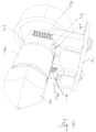
- the print head shown has a nozzle 1 for dispensing molten plastic material and a plastic housing 2 which encloses a tube 3 and supports a printed circuit board 6 with a control circuit.
- the tube 3 can, for example, be a cylindrical tube 3, that is to say it can have a circular-cylindrical outer surface.
- the pipe 3 is connected to the nozzle 1, for example screwed, and can have an internal thread for this purpose.
- the tube 3 shown together with the nozzle 1 carries an electrical heating element in the form of a heating layer 4 in order to melt plastic material in the nozzle 1.
- the tube can also be made in one piece with the nozzle.
- the heating layer 4 can be a printed or sprayed layer, for example a thick film resistor, or for example one of the Vapor-deposited layer, for example a thin-film resistor.
- the tube 3 can be made of electrically insulating material, for example ceramic, or of metal. If the tube 3 is a metal tube, the heating layer 4 lies on an electrically insulating intermediate layer. If the tube is made of an electrically insulating material, for example ceramic, the heating layer can be deposited directly on the tube or on an electrically insulating intermediate layer which can serve, for example, to improve adhesion.
- the print head is shown without the plastic housing 2.
- the heating layer 4 is connected to the control circuit via contact layers 5 with contact fields and contact tracks and spring contacts 7 to the control circuit.
- the spring contacts 7 can be designed as spring pins, for example, which press on the contact pads 5 .
- the heating current flows in the circumferential direction of the tube.
- the heating current can also flow in the longitudinal direction of the tube.
- the heating layer can then also be contacted, for example, via metal rings, for example made of copper, such as brass or bronze. These metal rings can be pushed onto the tube 3 or—in the case of open rings—also clipped on and preferably soldered to the contact track.
- the housing 2 can have plastic half-shells, for example, which are held together by screws 8 .
- the screws 8 can also be used to fasten the circuit board 6 to the plastic housing 2 .
- the control circuit can be connected to at least one temperature sensor 9 which measures the temperature of the tube 3 or determines the temperature of the plastic contained in the tube 3 . In this way, the temperature can be regulated very precisely to a setpoint.
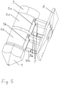
- FIG 5 Another embodiment of a print head is shown, which is shown without its plastic housing 2 for the sake of simplicity.
- This Embodiment differs from the embodiment of Figures 1 to 4 essentially only in that the tube 3 has a plurality of heating layers 4a, 4b and associated contact layers 5a, 5b next to one another and thus a plurality of independent heating zones are formed.
- These heating layers 4a, 4b are arranged one behind the other in the longitudinal direction of the tube 3 and are provided with connections, for example spring contacts 7, via contact layers 5a, 5b, via which they can be controlled independently of one another.
- connections for example spring contacts 7, via contact layers 5a, 5b, via which they can be controlled independently of one another.
- each heating layer 4a, 4b with its heating zone can be assigned a temperature sensor 9a, 9b.
- plastic material can be heated in a section adjacent to nozzle 1 in a first heating zone to a higher temperature optimal for dispensing plastic material for printing, and in a section of tube 3 remote from nozzle 1 in a second heating zone be preheated to a slightly lower temperature so that it can then be quickly melted in the vicinity of the nozzle 1.
Landscapes
- Chemical & Material Sciences (AREA)
- Engineering & Computer Science (AREA)
- Materials Engineering (AREA)
- Manufacturing & Machinery (AREA)
- Physics & Mathematics (AREA)
- Mechanical Engineering (AREA)
- Optics & Photonics (AREA)
- Ink Jet (AREA)
Applications Claiming Priority (1)
| Application Number | Priority Date | Filing Date | Title |
|---|---|---|---|
| DE102020123383.3A DE102020123383A1 (de) | 2020-09-08 | 2020-09-08 | Druckkopf für einen 3D-Drucker |
Publications (1)
| Publication Number | Publication Date |
|---|---|
| EP3965528A1 true EP3965528A1 (fr) | 2022-03-09 |
Family
ID=80053723
Family Applications (1)
| Application Number | Title | Priority Date | Filing Date |
|---|---|---|---|
| EP21195326.0A Pending EP3965528A1 (fr) | 2020-09-08 | 2021-09-07 | Tête d'impression pour une imprimante tridimensionnelle |
Country Status (2)
| Country | Link |
|---|---|
| EP (1) | EP3965528A1 (fr) |
| DE (1) | DE102020123383A1 (fr) |
Cited By (1)
| Publication number | Priority date | Publication date | Assignee | Title |
|---|---|---|---|---|
| EP4375050A1 (fr) | 2022-11-25 | 2024-05-29 | Eichenauer Heizelemente GmbH & Co. KG | Tête d'impression pour une imprimante 3d |
Citations (7)
| Publication number | Priority date | Publication date | Assignee | Title |
|---|---|---|---|---|
| US6129872A (en) * | 1998-08-29 | 2000-10-10 | Jang; Justin | Process and apparatus for creating a colorful three-dimensional object |
| US20120018924A1 (en) * | 2010-07-22 | 2012-01-26 | Stratasys, Inc. | Multiple-zone liquefier assembly for extrusion-based additive manufacturing systems |
| EP3476566A1 (fr) * | 2017-10-25 | 2019-05-01 | Chromalox, Inc. | Ensemble d'extrusion pour un système de fabrication additive et méthode pour son fabrication |
| EP3231581B1 (fr) | 2016-04-07 | 2019-05-01 | XYZprinting, Inc. | Imprimante trois dimensions et module de tête d'impression |
| WO2019175383A1 (fr) | 2018-03-16 | 2019-09-19 | Adient Engineering and IP GmbH | Tête de pulvérisation ou d'impression et ensemble tête de pulvérisation ou d'impression |
| EP3547796A1 (fr) * | 2016-11-28 | 2019-10-02 | Lintec of America, Inc. | Feuille conductrice pour moulage tridimensionnel |
| US20190366628A1 (en) * | 2018-04-16 | 2019-12-05 | Clay M. Guillory | Liquid Cooling for Pellet Extruder in a Fused Deposition Modeling System |
Family Cites Families (1)
| Publication number | Priority date | Publication date | Assignee | Title |
|---|---|---|---|---|
| US10131131B2 (en) | 2013-10-04 | 2018-11-20 | Stratasys, Inc. | Liquefier assembly with multiple-zone plate heater assembly |
-
2020
- 2020-09-08 DE DE102020123383.3A patent/DE102020123383A1/de active Pending
-
2021
- 2021-09-07 EP EP21195326.0A patent/EP3965528A1/fr active Pending
Patent Citations (7)
| Publication number | Priority date | Publication date | Assignee | Title |
|---|---|---|---|---|
| US6129872A (en) * | 1998-08-29 | 2000-10-10 | Jang; Justin | Process and apparatus for creating a colorful three-dimensional object |
| US20120018924A1 (en) * | 2010-07-22 | 2012-01-26 | Stratasys, Inc. | Multiple-zone liquefier assembly for extrusion-based additive manufacturing systems |
| EP3231581B1 (fr) | 2016-04-07 | 2019-05-01 | XYZprinting, Inc. | Imprimante trois dimensions et module de tête d'impression |
| EP3547796A1 (fr) * | 2016-11-28 | 2019-10-02 | Lintec of America, Inc. | Feuille conductrice pour moulage tridimensionnel |
| EP3476566A1 (fr) * | 2017-10-25 | 2019-05-01 | Chromalox, Inc. | Ensemble d'extrusion pour un système de fabrication additive et méthode pour son fabrication |
| WO2019175383A1 (fr) | 2018-03-16 | 2019-09-19 | Adient Engineering and IP GmbH | Tête de pulvérisation ou d'impression et ensemble tête de pulvérisation ou d'impression |
| US20190366628A1 (en) * | 2018-04-16 | 2019-12-05 | Clay M. Guillory | Liquid Cooling for Pellet Extruder in a Fused Deposition Modeling System |
Cited By (4)
| Publication number | Priority date | Publication date | Assignee | Title |
|---|---|---|---|---|
| EP4375050A1 (fr) | 2022-11-25 | 2024-05-29 | Eichenauer Heizelemente GmbH & Co. KG | Tête d'impression pour une imprimante 3d |
| DE102022131214A1 (de) | 2022-11-25 | 2024-05-29 | Eichenauer Heizelemente Gmbh & Co. Kg | Druckkopf für einen 3D-Drucker |
| US20240173916A1 (en) * | 2022-11-25 | 2024-05-30 | Eichenauer Heizelemente Gmbh & Co. Kg | Print head for a 3d printer |
| US12415313B2 (en) * | 2022-11-25 | 2025-09-16 | Eichenauer Heizelemente Gmbh & Co. Kg | Print head for a 3D printer |
Also Published As
| Publication number | Publication date |
|---|---|
| DE102020123383A1 (de) | 2022-03-10 |
Similar Documents
| Publication | Publication Date | Title |
|---|---|---|
| DE69915731T2 (de) | Giesssystem mit Filmheizungen und/oder -Sensoren | |
| DE60106579T2 (de) | Kompakte rohrheizkörperheisskanaldüse und verfahren zu ihrer herstellung | |
| DE60127679T2 (de) | Dickschicht heizvorrichtung | |
| DE102005018062B4 (de) | Verfahren zur Produktion von Heizeinrichtungen für Komponenten für Spritzgussgeräte | |
| EP2134143A1 (fr) | Elément de chauffe de résistance électrique pour un dispositif de chauffage destiné à chauffer un milieu gazeux s'écoulant | |
| EP2282179A1 (fr) | Procédé de fabrication d'une sonde de température pour un débitmètre du type thermique | |
| EP2274475B1 (fr) | Cylindre gaufreur chauffé | |
| CH663844A5 (de) | Thermischer massendurchflussmesser, insbesondere fuer gase. | |
| DE3303769A1 (de) | Waermeleistungsmesser | |
| EP2250857B1 (fr) | Élément chauffant électrique | |
| EP2739477B1 (fr) | Matrice d'estampage a chaud comportant des microstructures | |
| EP3965528A1 (fr) | Tête d'impression pour une imprimante tridimensionnelle | |
| DE19957991C2 (de) | Anordnung einer Heizschicht für einen Hochtemperaturgassensor | |
| DE212019000388U1 (de) | Wärmeaustauscheinheit und damit versehene Reinigungsvorrichtung | |
| DE102016102895A1 (de) | Wärmetauscher, insbesondere Wasser-Luft-Wärmetauscher oder Öl-Wasser-Wärmetauscher | |
| DE2801499A1 (de) | Extruder zur behandlung hochtemperaturempfindlicher kunststoffe | |
| EP3417210A1 (fr) | Échangeur de chaleur huile-eau, en particulier pour moteur à combustion interne d'un véhicule automobile | |
| DE3234894A1 (de) | Durchfluss-messvorrichtung | |
| DE102015225028A1 (de) | Spritzgiessvorrichtung mit beheizten Formhohlräumen | |
| DE202007001789U1 (de) | Spritzgießdüse | |
| DE102022206014A1 (de) | Heizeinrichtung und Kraftfahrzeug mit einer solchen Heizeinrichtung | |
| DE29515932U1 (de) | Durchlauferwärmungsvorrichtung | |
| DE102016204796A1 (de) | Messelement zur oberflächennahen Messung von physikalischen Größen, insbesondere von Temperaturen, in einer zumindest teilweise umschlossenen Kavität | |
| DE2912000A1 (de) | Vorrichtung zum vorwaermen von heizoel | |
| DE102022131214A1 (de) | Druckkopf für einen 3D-Drucker |
Legal Events
| Date | Code | Title | Description |
|---|---|---|---|
| PUAI | Public reference made under article 153(3) epc to a published international application that has entered the european phase |
Free format text: ORIGINAL CODE: 0009012 |
|
| STAA | Information on the status of an ep patent application or granted ep patent |
Free format text: STATUS: THE APPLICATION HAS BEEN PUBLISHED |
|
| AK | Designated contracting states |
Kind code of ref document: A1 Designated state(s): AL AT BE BG CH CY CZ DE DK EE ES FI FR GB GR HR HU IE IS IT LI LT LU LV MC MK MT NL NO PL PT RO RS SE SI SK SM TR |
|
| STAA | Information on the status of an ep patent application or granted ep patent |
Free format text: STATUS: REQUEST FOR EXAMINATION WAS MADE |
|
| 17P | Request for examination filed |
Effective date: 20220805 |
|
| RBV | Designated contracting states (corrected) |
Designated state(s): AL AT BE BG CH CY CZ DE DK EE ES FI FR GB GR HR HU IE IS IT LI LT LU LV MC MK MT NL NO PL PT RO RS SE SI SK SM TR |