EP3965340B1 - Zugangsknoten, benutzergerät, vorrichtungen, verfahren und computerprogramme zur bestimmung eines zeit-frequenz-rasters und pilotkonfiguration für eine funkverbindung zwischen zwei sendeempfängern eines mobilkommunikationssystems - Google Patents
Zugangsknoten, benutzergerät, vorrichtungen, verfahren und computerprogramme zur bestimmung eines zeit-frequenz-rasters und pilotkonfiguration für eine funkverbindung zwischen zwei sendeempfängern eines mobilkommunikationssystems Download PDFInfo
- Publication number
- EP3965340B1 EP3965340B1 EP20195017.7A EP20195017A EP3965340B1 EP 3965340 B1 EP3965340 B1 EP 3965340B1 EP 20195017 A EP20195017 A EP 20195017A EP 3965340 B1 EP3965340 B1 EP 3965340B1
- Authority
- EP
- European Patent Office
- Prior art keywords
- information
- communication system
- transceivers
- time
- frequency grid
- Prior art date
- Legal status (The legal status is an assumption and is not a legal conclusion. Google has not performed a legal analysis and makes no representation as to the accuracy of the status listed.)
- Active
Links
Images
Classifications
-
- H—ELECTRICITY
- H04—ELECTRIC COMMUNICATION TECHNIQUE
- H04L—TRANSMISSION OF DIGITAL INFORMATION, e.g. TELEGRAPHIC COMMUNICATION
- H04L5/00—Arrangements affording multiple use of the transmission path
- H04L5/003—Arrangements for allocating sub-channels of the transmission path
- H04L5/0058—Allocation criteria
- H04L5/0069—Allocation based on distance or geographical location
-
- H—ELECTRICITY
- H04—ELECTRIC COMMUNICATION TECHNIQUE
- H04L—TRANSMISSION OF DIGITAL INFORMATION, e.g. TELEGRAPHIC COMMUNICATION
- H04L5/00—Arrangements affording multiple use of the transmission path
- H04L5/003—Arrangements for allocating sub-channels of the transmission path
- H04L5/0048—Allocation of pilot signals, i.e. of signals known to the receiver
- H04L5/0051—Allocation of pilot signals, i.e. of signals known to the receiver of dedicated pilots, i.e. pilots destined for a single user or terminal
-
- H—ELECTRICITY
- H04—ELECTRIC COMMUNICATION TECHNIQUE
- H04L—TRANSMISSION OF DIGITAL INFORMATION, e.g. TELEGRAPHIC COMMUNICATION
- H04L5/00—Arrangements affording multiple use of the transmission path
- H04L5/0001—Arrangements for dividing the transmission path
- H04L5/0003—Two-dimensional division
- H04L5/0005—Time-frequency
- H04L5/0007—Time-frequency the frequencies being orthogonal, e.g. OFDM(A) or DMT
Definitions
- Embodiments of the present disclosure relate to an access node, user equipment, apparatuses methods, and computer programs for determining a time-frequency grid and pilot configuration for a radio link between two transceivers of a mobile communication system, more particularly, but not exclusively to a concept for adapting time-frequency grid and pilot configuration to a time and frequency dispersion (delay spread and Doppler shift) condition of a radio channel.
- Orthogonal frequency-division multiplexing is a popular and well-known modulation scheme but it may suffer from substantial performance degradation and inflexibility in environments with high Doppler spreads. Consequently, novel modulation schemes may be considered and perused which are flexible, efficient and robust in doubly-dispersive channels.
- V2I vehicle-to-infrastructure
- V2V direct vehicle-to-vehicle
- OTFS orthogonal time frequency and space
- OTFS outperforms OFDM in such situations.
- OTFS is a new modulation scheme that addresses the challenges of 5 th Generation mobile communication systems (5G).
- the key idea behind OTFS is to multiplex a QAM (quadrature amplitude modulation) or QPSK (Quadrature Phase Shift Keying) symbol (data) in the delay-Doppler signal representation.
- QAM quadrature amplitude modulation
- QPSK Quadrature Phase Shift Keying
- the wireless channel needs to be estimated at the receiver. This can be done by the insertion of pilots at the transmitter.
- the a-priory known pilot tones can be used by the receiver to estimate the channel.
- Document US 2020/0014512 A1 relates to a mobile communication device, comprising: a receiver, configured to receive a radio signal over a radio channel, the radio signal comprising a predetermined pilot preamble; and a processor, configured to determine mobility information, in particular a Doppler and/or a Delay Spread, based on the pilot preamble, wherein the processor is further configured to signal the mobility information to a second communication device.
- the disclosure further relates to a base station, comprising: a receiver, configured to receive mobility information, in particular a Doppler and/or a Delay Spread, signaled by a mobile communication device; and a processor, configured to select a numerology based on the mobility information and to generate a radio signal for transmission to the communication device based on the numerology.
- a base station comprising: a receiver, configured to receive mobility information, in particular a Doppler and/or a Delay Spread, signaled by a mobile communication device; and a processor, configured to select a numerology based on the mobility information and to generate a radio signal for transmission to the communication device based on the numerology.
- Document US 2018/0049073 A1 describes a base station, which receives, from a wireless device, a message comprising a first sequence of a plurality of parameters.
- a first parameter in the first sequence indicates whether a V2X transmission configuration is supported in a first band combination.
- the first band combination may be in a second sequence of a plurality of band combinations associated with the wireless device.
- An index of the first parameter in the first sequence identifies the first band combination in the second sequence.
- a second message may be transmitted based on the message.
- the second message comprises configuration parameters of at least one cell for V2X communications.
- the at least one cell operates in one of the plurality of band combinations that supports the V2X transmission configuration.
- Document US 2020/0045562 A1 discloses methods of using OTFS pilot symbol waveform bursts to automatically produce a detailed 2D model of a channel state. This 2D channel state can then be used to optimize data transmission. For wireless data channels, an even more detailed 2D model of channel state can be produced by using polarization and multiple antennas in the process. Once 2D channel states are known, the system turns imperfect data channels from a liability to an advantage by using channel imperfections to boost data transmission rates. The methods can be used to improve legacy data transmission modes in multiple types of media and are particularly useful for producing new types of robust and high capacity wireless communications using non-legacy OTFS data transmission methods.
- Document US 2003/0064733 A1 provides a terminal location estimation method capable of accurately estimating a location of a mobile terminal when providing information services according to the location of the terminal in a radio communication system.
- a positioning server sends a location measurement probe message to the mobile terminal in order to measure the location of the terminal.
- Each of base stations receives a response message broadcasted from the terminal, measures the reception level and delay spread and sends the measurement results to the positioning server.
- the positioning server has a radio wave propagation estimating portion and a database for storing estimation results thereof. The server estimates the location of the terminal by checking the measurement results of the base stations against the estimation results on radio wave propagation stored in the database.
- Embodiments are based on the finding that a time-frequency grid configuration for a radio link can be made adaptive together with a pilot configuration.
- the time-frequency grid and pilot configuration can be based on a delay spread and a Doppler shift of the radio link. These parameters may be determined from a relative velocity between two transmitters and predetermined information on the delay spread.
- Embodiments provide a method for determining a time-frequency grid and pilot configuration for a radio link between two transceivers of a mobile communication system.
- the method comprises obtaining information on a relative velocity between the two transceivers and retrieving predetermined information on a delay spread of a radio channel between two transceivers.
- the method further comprises deriving the time-frequency grid configuration for the radio link based on the information on the relative velocity and based on the information on the delay spread and determining the pilot configuration in relation to the time-frequency grid.
- Embodiments enable adaptation of a time-frequency grid and pilot configuration related thereto based on a delay-Doppler condition of a radio channel.
- the pilot configuration may be determined in a delay-Doppler domain.
- Embodiments may enable adaptation of the pilot configuration to the delay-Doppler characteristics in the delay-Doppler domain, which may enable pilot configuration tailored to the channel characteristics, be it for OTFS, OFDM or any other waveform.
- one of the two transceivers may be static and the other of the two transceivers may be mobile.
- the obtaining of the information on the relative velocity may comprise communicating information on a velocity of the transceiver, which is mobile. Knowledge on a velocity of the mobile transceiver may enable estimation of a Doppler shift of the radio channel.
- the determining of the information on the delay spread may be based on a location of the mobile transceiver.
- Embodiments may use predetermined radio channel information for different locations.
- the transceiver which is static, is an access node of the mobile communication system.
- Embodiments may determine relative velocities for Doppler shift estimation and delay spread radio maps relative to a base station or access node of the mobile communication system.
- the transceiver which is mobile, may be a vehicle and embodiments may enable efficient channel estimation in vehicular communication.
- the deriving may be further based on information on driving directions and/or information on a future planned trajectory of the vehicle. Information on future or planned trajectories of vehicles may be used in embodiments.
- the retrieving of the predetermined information on the delay spread is based on delay spread information stored in a data base.
- a data base may enable efficient restoring of delay spread information for a radio channel.
- the data base comprises a three-dimensional radio map of delay spreads.
- Embodiments may enable efficient granularity, may be even in the third dimension, for storing radio maps.
- the deriving of the time-frequency grid configuration may further comprise selecting one out of a limited group of mobility modes, the mobility modes having different time-frequency grid configurations.
- Embodiments may select from a predefined group of mobility modes to enable efficient selection and time-efficient assignment of a time-frequency grid and pilot configuration.
- the method may further comprise measuring information on the delay spread and storing the information on the delay spread.
- Embodiments may enable efficient sensing and updating of the predetermined delay spread information.
- Embodiments further provide a computer program having a program code for performing one or more of the above described methods, when the computer program is executed on a computer, processor, or programmable hardware component.
- a further embodiment is a computer readable storage medium storing instructions which, when executed by a computer, processor, or programmable hardware component, cause the computer to implement one of the methods described herein.
- Another embodiment is an apparatus for determining a time-frequency grid configuration for a radio link between two transceivers of a mobile communication system.
- the apparatus comprises a transceiver module for communicating in the mobile communication system and a processing module, which is configured to control the transceiver module and to perform at least one method as described herein.
- An access node of a wireless communication system comprising an embodiment of the apparatus is another embodiment.
- User equipment for a wireless communication system comprising an embodiment of the apparatus is yet another embodiment.
- the term “or” refers to a non-exclusive or, unless otherwise indicated (e.g., “or else” or “or in the alternative”).
- words used to describe a relationship between elements should be broadly construed to include a direct relationship or the presence of intervening elements unless otherwise indicated. For example, when an element is referred to as being “connected” or “coupled” to another element, the element may be directly connected or coupled to the other element or intervening elements may be present. In contrast, when an element is referred to as being “directly connected” or “directly coupled” to another element, there are no intervening elements present. Similarly, words such as “between”, “adjacent”, and the like should be interpreted in a like fashion.
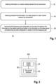
- Fig. 1 illustrates a block diagram of an embodiment of a method 10 for determining a time-frequency grid and pilot configuration for a radio link between two transceivers of a mobile communication system.
- the method 10 comprises obtaining 12 information on a relative velocity between the two transceivers and retrieving 14 predetermined information on a delay spread of a radio channel between two transceivers.
- the method 10 further comprises deriving 16 the time-frequency grid configuration for the radio link based on in the information on the relative velocity and based on the information on the delay spread and determining the pilot configuration in relation to the time-frequency grid.
- the relative velocity can be used to derive or estimate a maximum Doppler shift of the radio channel.
- the maximum Doppler shift may be one determining factor for time-frequency (TF) grid selection and pilot configuration. For example, the higher the maximum Doppler spread the wider a subcarrier spacing and/or a subcarrier bandwidth in the TF grid.
- the predetermined delay spread information may be another determining factor. For example, the longer a delay spread in the radio channel the longer a symbol duration in the TF grid.
- the pilot configuration is determined in a delay-Doppler domain. This may enable to match a pilot symbol distribution to the actual inter-symbol interference generated by a current channel realization, which may enable a higher efficiency.
- Such pilot insertion or determination in the delay-Doppler domain may be carried out independently of the waveform, e.g. in any multicarrier system, OFDM, OTFS, etc.
- Fig. 2 illustrates a block diagram of an embodiment of an apparatus 20 for determining a time-frequency grid configuration for a radio link between two transceivers of a mobile communication system, an embodiment of an access node, and an embodiment of user equipment.
- the apparatus 20 for determining a time-frequency grid configuration for a radio link between two transceivers of the mobile communication system comprises a transceiver module 22 for communicating in the mobile communication system and a processing module 24, which is coupled to the transceiver module 22.
- the processing module 24 is configured to control the transceiver module 22 and to perform at least one of the methods 10 described herein.
- the apparatus 20 may be comprised in another entity 200, which is shown in broken lines in Fig. 2 as it is optional from the perspective of the apparatus 20.
- the other entity 200 may be an access node of the mobile communication system or user equipment/vehicle comprising an embodiment of the apparatus 20.
- the transceiver module 22 may be implemented as any means for transmitting, receiving or transceiving, i.e. receiving and/or transmitting etc., one or more transmitter/receiver units, one or more transmitter/receiver devices and it may comprise typical receiver and/or transmitter components, such as one or more elements of the group of one or more Low-Noise Amplifiers (LNAs), one or more Power Amplifiers (PAs), one or more filters or filter circuitry, one or more diplexers, one or more duplexers, one or more Analog-to-Digital converters (A/D), one or more Digital-to-Analog converters (D/A), one or more modulators or demodulators, one or more mixers, one or more antennas, etc.
- LNAs Low-Noise Amplifiers
- PAs Power Amplifiers
- filters or filter circuitry one or more diplexers, one or more duplexers, one or more Analog-to-Digital converters (A/D
- the processing module 24 may provide some functionality that may be found in transceiver modules.
- the processing module 24 may be a processing module of the transmitter/receiver/transceiver module 22 and may comprise one or more filters or filter circuitry and/or one or more modulators or demodulators.
- the processing module 24 may be implemented using one or more processing units, one or more processing devices, any means for processing, such as a processor, a computer or a programmable hardware component being operable with accordingly adapted software.
- the described function of the processing module 24 may as well be implemented in software, which is then executed on one or more programmable hardware components.
- Such hardware components may comprise a general-purpose processor, a Digital Signal Processor (DSP), a micro-controller, etc.
- DSP Digital Signal Processor
- the respective processing module 24 may be configured to carry out any of the methods 10 described herein.
- the wireless devices may be any devices of a wireless communication system using OTFS or OFDM, e.g. a mobile communication system, a broadcast system, a unicast system etc.
- the apparatus 20 and the vehicle, control center, or network component 200 may communicate at least partly through a mobile communication system.
- the mobile communication system may, for example, correspond to one of the Third Generation Partnership Project (3GPP)-standardized mobile communication networks, where the term mobile communication system is used synonymously to mobile communication network.
- 3GPP Third Generation Partnership Project
- Data and control information may hence be communicated through multiple network nodes (e.g. internet, router, switches, etc.) and the mobile communication system, which generates the delay or latencies considered in embodiments.
- the mobile or wireless communication system may correspond to a mobile communication system of the 5th Generation (5G, or New Radio) or beyond and may use mm-Wave technology.
- the mobile communication system may correspond to or comprise, for example, a Long-Term Evolution (LTE), an LTE-Advanced (LTE-A), High Speed Packet Access (HSPA), a Universal Mobile Telecommunication System (UMTS) or a UMTS Terrestrial Radio Access Network (UTRAN), an evolved-UTRAN (e-UTRAN), a Global System for Mobile communication (GSM) or Enhanced Data rates for GSM Evolution (EDGE) network, a GSM/EDGE Radio Access Network (GERAN), or mobile communication networks with different standards, for example, a Worldwide Inter-operability for Microwave Access (WIMAX) network IEEE 802.16 or Wireless Local Area Network (WLAN) IEEE 802.11, generally an Orthogonal Frequency Division Multiple Access (OFDMA) network, a Time Division Multiple Access (TDMA) network, a Code Division Multiple Access (CDMA) network,
- Service provision may be carried out by a network component, such as a base station transceiver, a relay station or a UE, e.g. coordinating service provision in a cluster or group of multiple UEs/vehicles.
- a base station transceiver can be operable or configured to communicate with one or more active mobile transceivers/vehicles and a base station transceiver can be located in or adjacent to a coverage area of another base station transceiver, e.g. a macro cell base station transceiver or small cell base station transceiver.
- embodiments may provide a mobile communication system comprising two or more mobile transceivers/vehicles and one or more base station transceivers, wherein the base station transceivers may establish macro cells or small cells, as e.g. pico-, metro-, or femto cells.
- a mobile transceiver or UE may correspond to a smartphone, a cell phone, a laptop, a notebook, a personal computer, a Personal Digital Assistant (PDA), a Universal Serial Bus (USB) -stick, a car, a vehicle, a road participant, a traffic entity, traffic infrastructure etc.
- PDA Personal Digital Assistant
- USB Universal Serial Bus
- a mobile transceiver may also be referred to as User Equipment (UE) or mobile in line with the 3GPP terminology.
- UE User Equipment
- a vehicle may correspond to any conceivable means for transportation, e.g. a car, a bike, a motorbike, a van, a truck, a bus, a ship, a boat, a plane, a train, a tram, etc.
- a base station transceiver can be located in the fixed or stationary part of the network or system.
- a base station transceiver may be or correspond to a remote radio head, a transmission point, an access point, a macro cell, a small cell, a micro cell, a femto cell, a metro cell etc.
- a base station transceiver can be a wireless interface of a wired network, which enables transmission of radio signals to a UE or mobile transceiver.
- Such a radio signal may comply with radio signals as, for example, standardized by 3GPP or, generally, in line with one or more of the above listed systems.
- a base station transceiver may correspond to a NodeB, an eNodeB, a gNodeB, a Base Transceiver Station (BTS), an access point, a remote radio head, a relay station, a transmission point, etc., which may be further subdivided in a remote unit and a central unit.
- BTS Base Transceiver Station
- a mobile transceiver or vehicle can be associated with a base station transceiver or cell.
- the term cell refers to a coverage area of radio services provided by a base station transceiver, e.g. a NodeB (NB), an eNodeB (eNB), a gNodeB, a remote radio head, a transmission point, etc.
- a base station transceiver may operate one or more cells on one or more frequency layers, in some embodiments a cell may correspond to a sector. For example, sectors can be achieved using sector antennas, which provide a characteristic for covering an angular section around a remote unit or base station transceiver.
- a base station transceiver may operate multiple sectorized antennas.
- a cell may represent an according base station transceiver generating the cell or, likewise, a base station transceiver may represent a cell the base station transceiver generates.
- the apparatus 20 may be comprised in a server, a base station, a NodeB, a UE, a vehicle, a network component, a relay station, or any service coordinating network entity in embodiments.
- network component may comprise multiple sub-components, such as a base station, a server, etc.
- the transceiver module 22 may comprise or implement one or more interfaces, which may correspond to any means for obtaining, receiving, transmitting or providing analog or digital signals or information, e.g. any connector, contact, pin, register, input port, output port, conductor, lane, etc. which allows providing or obtaining a signal or information.
- An interface may be wireless or wireline and it may be configured to communicate, i.e. transmit or receive signals, information with further internal or external components.
- the one or more interfaces may comprise further components to enable according communication in the (mobile) communication system, such components may include transceiver (transmitter and/or receiver) components, such as one or more Low-Noise Amplifiers (LNAs), one or more Power-Amplifiers (PAs), one or more duplexers, one or more diplexers, one or more filters or filter circuitry, one or more converters, one or more mixers, accordingly adapted radio frequency components, etc.
- the one or more interfaces may be coupled to one or more antennas, which may correspond to any transmit and/or receive antennas, such as horn antennas, dipole antennas, patch antennas, sector antennas etc.
- the one or more interfaces may serve the purpose of transmitting or receiving or both, transmitting and receiving, information, such as information, input data, control information, further information messages, etc.
- communication i.e. transmission, reception or both, may take place among mobile transceivers/vehicles directly, e.g. forwarding input data or control information to/from a control center.
- Such communication may make use of a mobile communication system.
- Such communication may be carried out directly, e.g. by means of Device-to-Device (D2D) communication.
- D2D Device-to-Device
- Such communication may be carried out using the specifications of a mobile communication system.
- An example of D2D is direct communication between vehicles, also referred to as Vehicle-to-Vehicle communication (V2V), car-to-car, Dedicated Short Range Communication (DSRC), respectively. Technologies enabling such D2D-communication include 802.11p, 3GPP systems (4G, 5G, NR and beyond), etc.
- the transceiver module 22 can be configured to wirelessly communicate in the mobile communication system, e.g. in an embodiment in which the apparatus 20 is implemented in a vehicle and the method 10 is carried out at the vehicle.
- radio resources e.g. frequency, time, code, and/or spatial resources, which may be used for wireless communication with a base station transceiver as well as for direct communication.
- the assignment of the radio resources may be controlled by a base station transceiver, i.e. the determination which resources are used for D2D and which are not.
- radio resources of the respective components may correspond to any radio resources conceivable on radio carriers and they may use the same or different granularities on the respective carriers.
- the radio resources may correspond to a Resource Block (RB as in LTE/LTE-A/LTE-unlicensed (LTE-U)), one or more carriers, sub-carriers, one or more radio frames, radio sub-frames, radio slots, one or more code sequences potentially with a respective spreading factor, one or more spatial resources, such as spatial sub-channels, spatial precoding vectors, any combination thereof, etc.
- RB Resource Block
- LTE-U LTE/LTE-A/LTE-unlicensed
- spatial resources such as spatial sub-channels, spatial precoding vectors, any combination thereof, etc.
- C-V2X direct Cellular Vehicle-to-Anything
- V2X includes at least V2V, V2-Infrastructure (V2I), etc.
- transmission according to 3GPP Release 14 onward can be managed by infrastructure (so-called mode 3) or run in a UE.
- a transform is used to transform the symbols from the time-frequency domain to the time domain.
- This central transformation is called Gabor transform (or also refer as Weyl-Heisenberg signaling).
- the Gabor filterbank is responsible for the generation of the waveform and the transmit pulse which is often matched with the receive pulse.
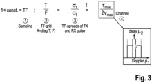
- Fig. 3 depicts how the grid and pulses should match the channel realization from a theoretical viewpoint. With so called mobility modes embodiments may intend to be as close as possible to the equality in Fig. 3 .
- Fig. 3 illustrates multi-carrier Gabor pulse designing rules for ideal and an efficient communication in dependency on the channel delay and Doppler shifts in an embodiment.
- Fig. 3 illustrates four steps 1, 2, 3, 4 from left to right.
- T / F of a symbol duration T over the subcarrier bandwidth F equals (step 3) ⁇ t / ⁇ f , which is the relation of the channel's time variance ⁇ t (delay spread) over the channel's frequency variance ⁇ f (Doppler shift).
- ⁇ max represents the maximum delay spread of the radio channel and ⁇ max represents the maximum Doppler shift.
- Fig. 3 further indicates a delay-Doppler plane showing two different channel realizations, with different maximum delay and Doppler spreads.
- Embodiments may enable a time-frequency grid matching and pulse shaping for multicarrier signaling waveforms under changing mobility conditions and hence changing communication/radio channel.
- Fig. 3 shows the four steps which need to be taken into account in order to obtain an (theoretically) ideal TF-grid matching and an efficient system in embodiments.
- the ratio of the time and frequency grid T/F needs to be close to the ratio between the delay ( ⁇ max ) and Doppler (2 ⁇ max ) spread of the communication channel.
- the transmitter needs to know the communication channel in advance (delay, and Doppler spread, cf. 12 and 14 in Fig. 1 ) and second the receiver needs to know the used grid matching and pulse design of the transmitter in order to be able to demodulate the waveform in a most efficient way.
- the method 10 may hence comprise communicating information on the time-frequency grid configuration and pilot configuration.
- the ratio of (delay/2 Doppler spread) is varying.
- Some embodiments choose T, F grid matching and transmit and receive pulse depending on the ratio delay/Doppler of the communication/radio channel:
- the ratio ⁇ max /(2 ⁇ max ) depends on:
- one of the two transceivers is static and the other of the two transceivers is mobile.
- the transceiver, which is mobile may be a vehicle and the transceiver, which is static, is an access node of the mobile communication system.
- the obtaining 12 of the information on the relative velocity may then comprise communicating information on a velocity of the transceiver, which is mobile.
- the retrieving 14 of the information on the delay spread can be based on a location of the transceiver, which is mobile.
- a geographical 3-D radio map with a data base of delay spreads may be stored in the system, e.g. on a server.
- the radio map may store information on a delay spread of the respective radio channel between said location and the access node or base station.
- the retrieving 14 of the predetermined information on the delay spread is based on delay spread information stored in the data base/on the server.
- the data base comprises a three-dimensional radio map of delay spreads.
- the radio map may be updated, e.g. the method 10 may comprise measuring information on the delay spread and storing the information on the delay spread. That way, the data base can be updated, for example, a time cycle for measuring the radio channel and updating the data base may be implemented. Such a cycle may be once an hour, a day, one a week, once a month, etc.
- a vehicle may share its speed, driving directions, and future planned trajectory (e.g. up to approx. 5s, 10s, 20s, etc.).
- the deriving 16 may be further based on information on driving directions and/or information on a future planned trajectory of the vehicle.
- a base station or access node may then manage the resource allocation depending on the estimated best grid configuration (mobility mode) and may then derive and assign the TF grid and pilot configuration.
- the deriving 16 of the time-frequency grid configuration may further comprise selecting one out of a limited group of mobility modes.
- the mobility modes have different time-frequency grid configurations.
- a mobility mode may be defined by a combination of a certain symbol duration and subcarrier spacing and a pilot configuration related thereto.
- different pilot configurations (constellation of pilot and guard symbols) may be used for the same time-frequency grid in different mobility modes.
- a pilot density in the time and frequency domains may dependent on a coherence time and bandwidth of the radio channel and different modes (pilot configurations) may be used in embodiments for the same symbol duration and subcarrier spacing.
- the base station or access node may maintain the data base with the radio map.
- Mode N M T F T/F OFDM 64 64 0.125 ⁇ s 156.25kHz 8e-13 I 64 64 0.125 ⁇ s 156.25kHz 8e-13 II 32 128 0.5 ⁇ s 79.125kHz 6.4e-12 III 128 32 31.25ns 312.5kHz 1e-13 IV 16 256 2 ⁇ s 39.063kHz 5.12e-11 V 256 16 62.5ns 625kHz 1.25e-14 VI 8 512 8 ⁇ s 19.531 kHz 4.096e-10 VII 512 8 1.953ns 1250kHz 1,5625e-15
- the TF grid is sampled with T and F period in the time and frequency domain, respectively.
- the mobility modes may be defined and/or adapted based on a long-term expectation of the radio channel.
- the proposed mobility modes are aiming to reduce the impact of self-interference.
- the remaining self-interference power may then be estimated and used for linear equalization.
- the above table presents the mobility modes I to XII in an embodiment.
- other mobility modes and sets of mobility modes to select from may be defined.
- Mode I represents the case for equal time and frequency resolution.
- Each mobility mode therefore may use its own pulse shape.
- Transmitter and the receiver may use the same mode.
- the appropriate mode can be selected depending on the second order statistic of the channel.
- Examples may further be or relate to a computer program having a program code for performing one or more of the above methods, when the computer program is executed on a computer or processor. Steps, operations or processes of various above-described methods may be performed by programmed computers or processors. Examples may also cover program storage devices such as digital data storage media, which are machine, processor or computer readable and encode machine-executable, processor-executable or computer-executable programs of instructions. The instructions perform or cause performing some or all of the acts of the above-described methods.
- the program storage devices may comprise or be, for instance, digital memories, magnetic storage media such as magnetic disks and magnetic tapes, hard drives, or optically readable digital data storage media.
- FIG. 1 may also cover computers, processors or control units programmed to perform the acts of the above-described methods or (field) programmable logic arrays ((F)PLAs) or (field) programmable gate arrays ((F)PGAs), programmed to perform the acts of the above-described methods.
- a functional block denoted as "means for " performing a certain function may refer to a circuit that is configured to perform a certain function.
- a "means for s.th.” may be implemented as a "means configured to or suited for s.th.”, such as a device or a circuit configured to or suited for the respective task.
- Functions of various elements shown in the figures may be implemented in the form of dedicated hardware, such as “a signal provider”, “a signal processing unit”, “a processor”, “a controller”, etc. as well as hardware capable of executing software in association with appropriate software.
- a processor the functions may be provided by a single dedicated processor, by a single shared processor, or by a plurality of individual processors, some of which or all of which may be shared.
- processor or “controller” is by far not limited to hardware exclusively capable of executing software, but may include digital signal processor (DSP) hardware, network processor, application specific integrated circuit (ASIC), field programmable gate array (FPGA), read only memory (ROM) for storing software, random access memory (RAM), and non-volatile storage.
- DSP digital signal processor
- ASIC application specific integrated circuit
- FPGA field programmable gate array
- ROM read only memory
- RAM random access memory
- non-volatile storage non-volatile storage.
- a block diagram may, for instance, illustrate a high-level circuit diagram implementing the principles of the disclosure.
- a flow chart, a flow diagram, a state transition diagram, a pseudo code, and the like may represent various processes, operations or steps, which may, for instance, be substantially represented in computer readable medium and so executed by a computer or processor, whether or not such computer or processor is explicitly shown.
- Methods disclosed in the specification or in the claims may be implemented by a device having means for performing each of the respective acts of these methods.
Landscapes
- Engineering & Computer Science (AREA)
- Signal Processing (AREA)
- Computer Networks & Wireless Communication (AREA)
- Mobile Radio Communication Systems (AREA)
Claims (15)
- Verfahren (10) zum Bestimmen eines Zeit-Frequenz-Rasters und einer Pilotkonfiguration für eine Funkverbindung zwischen zwei Senderempfängern eines mobilen Kommunikationssystems, wobei das Verfahren (10) umfasstErhalten (12) von Informationen über eine relative Geschwindigkeit zwischen den beiden Senderempfängern;Abrufen (14) von vorbestimmten Informationen über eine Verzögerungsspanne eines Funkkanals zwischen zwei Senderempfängern; undAbleiten (16) der Zeit-Frequenz-Rasterkonfiguration für die Funkverbindung basierend auf den Informationen über die Relativgeschwindigkeit und basierend auf den Informationen über die Verzögerungsspanne und Bestimmen der Pilotkonfiguration in Bezug auf das Zeit-Frequenz-Raster.
- Verfahren (10) nach Anspruch 1, wobei die Pilotkonfiguration in einem Verzögerungs-Doppler-Bereich bestimmt wird.
- Verfahren (10) nach einem der Ansprüche 1 oder 2, wobei einer der beiden Senderempfänger statisch und der andere der beiden Senderempfänger mobil ist und wobei das Erhalten (12) der Informationen über die Relativgeschwindigkeit das Kommunizieren von Informationen über eine Geschwindigkeit des Senderempfängers umfasst, der mobil ist.
- Verfahren (10) nach Anspruch 3, wobei das Abrufen (14) der Informationen über die Verzögerungsspanne auf einer Position des Senderempfängers basiert, der mobil ist.
- Verfahren (10) nach einem der Ansprüche 3 oder 4, wobei der Senderempfänger, der statisch ist, ein Zugangsknoten des mobilen Kommunikationssystems ist.
- Verfahren (10) nach einem der Ansprüche 3 bis 5, wobei der Senderempfänger, der mobil ist, ein Fahrzeug ist.
- Verfahren (10) nach Anspruch 6, wobei das Ableiten (16) ferner auf Informationen über Fahrtrichtungen und/oder Informationen über eine zukünftig geplante Bewegungsbahn des Fahrzeugs basiert.
- Verfahren (10) nach einem der Ansprüche 1 bis 7, wobei das Abrufen (16) der vorbestimmten Informationen über die Verzögerungsspanne auf den in einer Datenbank gespeicherten Verzögerungsspanneninformationen basiert.
- Verfahren (10) nach Anspruch 8, wobei die Datenbank eine dreidimensionale Funkkarte von Verzögerungsspannen umfasst.
- Verfahren (10) nach einem der Ansprüche 1 bis 9, wobei das Ableiten (16) der Zeit-Frequenz-Rasterkonfiguration ferner das Auswählen einer aus einer begrenzten Gruppe von Mobilitätsmodi umfasst, wobei die Mobilitätsmodi unterschiedliche Zeit-Frequenz-Rasterkonfigurationen aufweisen.
- Verfahren (10) nach einem der Ansprüche 1 bis 10, das ferner das Messen von Informationen über die Verzögerungsspanne und das Speichern der Informationen über die Verzögerungsspanne umfasst.
- Computerprogramm mit einem Programmcode zum Durchführen mindestens eines Verfahrens (10) nach einem der Ansprüche 1 bis 11, wenn das Computerprogramm auf einem Computer, einem Prozessor oder einer programmierbaren Hardwarekomponente ausgeführt wird.
- Vorrichtung (20) zum Bestimmen eines Zeit-Frequenz-Rasters und einer Pilotkonfiguration für eine Funkverbindung zwischen zwei Sendeempfängern eines mobilen Kommunikationssystems, wobei die Vorrichtung (20) umfasst:ein Senderempfängermodul (22) zum Kommunizieren in dem mobilen Kommunikationssystem; undein Verarbeitungsmodul (24), das dazu konfiguriert ist:das Senderempfängermodul (22) zu steuern, undmindestens ein Verfahren (10) nach einem der Ansprüche 1 bis 11 durchzuführen.
- Zugangsknoten (200) eines drahtlosen Kommunikationssystems, der die Vorrichtung (20) nach Anspruch 13 umfasst.
- Benutzergerät (200) für ein drahtloses Kommunikationssystem, das die Vorrichtung (20) nach Anspruch 13 umfasst.
Priority Applications (1)
| Application Number | Priority Date | Filing Date | Title |
|---|---|---|---|
| EP20195017.7A EP3965340B1 (de) | 2020-09-08 | 2020-09-08 | Zugangsknoten, benutzergerät, vorrichtungen, verfahren und computerprogramme zur bestimmung eines zeit-frequenz-rasters und pilotkonfiguration für eine funkverbindung zwischen zwei sendeempfängern eines mobilkommunikationssystems |
Applications Claiming Priority (1)
| Application Number | Priority Date | Filing Date | Title |
|---|---|---|---|
| EP20195017.7A EP3965340B1 (de) | 2020-09-08 | 2020-09-08 | Zugangsknoten, benutzergerät, vorrichtungen, verfahren und computerprogramme zur bestimmung eines zeit-frequenz-rasters und pilotkonfiguration für eine funkverbindung zwischen zwei sendeempfängern eines mobilkommunikationssystems |
Publications (2)
| Publication Number | Publication Date |
|---|---|
| EP3965340A1 EP3965340A1 (de) | 2022-03-09 |
| EP3965340B1 true EP3965340B1 (de) | 2024-08-21 |
Family
ID=72432707
Family Applications (1)
| Application Number | Title | Priority Date | Filing Date |
|---|---|---|---|
| EP20195017.7A Active EP3965340B1 (de) | 2020-09-08 | 2020-09-08 | Zugangsknoten, benutzergerät, vorrichtungen, verfahren und computerprogramme zur bestimmung eines zeit-frequenz-rasters und pilotkonfiguration für eine funkverbindung zwischen zwei sendeempfängern eines mobilkommunikationssystems |
Country Status (1)
| Country | Link |
|---|---|
| EP (1) | EP3965340B1 (de) |
Families Citing this family (1)
| Publication number | Priority date | Publication date | Assignee | Title |
|---|---|---|---|---|
| CN114786132B (zh) * | 2022-06-16 | 2022-09-02 | 北京邮电大学 | 目标追踪方法、装置、电子设备和存储介质 |
Family Cites Families (5)
| Publication number | Priority date | Publication date | Assignee | Title |
|---|---|---|---|---|
| JP2003116164A (ja) * | 2001-10-03 | 2003-04-18 | Nec Corp | 測位システム、測位サーバ、無線基地局及びそれに用いる端末位置推定方法 |
| US9444514B2 (en) * | 2010-05-28 | 2016-09-13 | Cohere Technologies, Inc. | OTFS methods of data channel characterization and uses thereof |
| EP3295572A4 (de) * | 2015-05-11 | 2018-12-26 | Cohere Technologies, Inc. | Systeme und verfahren für symplektische orthogonale zeitfrequenzverschiebungsmodulation und übertragung von daten |
| EP3498008B1 (de) | 2016-08-10 | 2020-11-04 | Ofinno, LLC | Konfiguration einer semipersistenten planung und v2x in einem drahtlosen netzwerk |
| CN110366835B (zh) | 2017-03-16 | 2021-03-23 | 华为技术有限公司 | 基于自适应参数集的通信技术 |
-
2020
- 2020-09-08 EP EP20195017.7A patent/EP3965340B1/de active Active
Also Published As
| Publication number | Publication date |
|---|---|
| EP3965340A1 (de) | 2022-03-09 |
Similar Documents
| Publication | Publication Date | Title |
|---|---|---|
| EP4236223B1 (de) | Systeme und verfahren für system mit mehreren physikalischen strukturen | |
| CN108370360A (zh) | 基于零尾及唯一字的dft-s ofdm和ofdm波形 | |
| US11245463B2 (en) | Wireless communication device and corresponding apparatus, method and computer program | |
| EP3809651B1 (de) | Drahtloskommunikationsvorrichtung und zugehörige einrichtung, verfahren und computerprogramm | |
| US11632272B1 (en) | Multiplexing demodulation reference signal and data in orthogonal time frequency space waveform | |
| US11438110B2 (en) | Wireless communication device and corresponding apparatus, method and computer program | |
| US12567914B2 (en) | Methods, computer programs and apparatuses for determining and using a predicted future quality of service of a wireless communication link | |
| US20210111786A1 (en) | Wireless Communication Device and Corresponding Apparatus, Method and Computer Program | |
| CN101939943A (zh) | 用于在多天线ofdm系统中选取循环延迟的方法和系统 | |
| US11336405B2 (en) | Wireless communication device and corresponding apparatus, method and computer program | |
| EP3965340B1 (de) | Zugangsknoten, benutzergerät, vorrichtungen, verfahren und computerprogramme zur bestimmung eines zeit-frequenz-rasters und pilotkonfiguration für eine funkverbindung zwischen zwei sendeempfängern eines mobilkommunikationssystems | |
| US12273226B2 (en) | Access node, user equipment, apparatus, method and computer program for determining a delay-doppler-resolution for a transceiver of a mobile communication system | |
| US11457342B2 (en) | Vehicle, network entity, apparatuses, methods, and computer programs for communicating messages with other vehicles and for adapting a physical layer configuration | |
| US20240118432A1 (en) | Access node, user equipment, apparatus, method and computer program for determining a delay-doppler resolution for a radio link between two transceivers of a mobile communication system | |
| EP4099600A1 (de) | Zugangsknoten, benutzergerät, verfahren, geräte und computerprogramme zum senden und empfangen von daten in einem mobilen kommunikationssystem | |
| EP3809653B1 (de) | Drahtloskommunikationsvorrichtung und zugehörige einrichtung, verfahren und computerprogramm | |
| EP4199645A1 (de) | Verfahren für einen sender zur erhöhung der übertragungskapazität, verfahren für einen empfänger, gerät, fahrzeug und computerprogramm | |
| US12425272B2 (en) | Channel estimation method and apparatus, communication device, and storage medium | |
| US11863971B2 (en) | Transportation vehicle, system, apparatuses, methods, and computer programs for user equipment and a network component of a mobile communication system | |
| Lee et al. | Performance comparison of V2V communication based on LTE-D2D with cooperative schemes |
Legal Events
| Date | Code | Title | Description |
|---|---|---|---|
| PUAI | Public reference made under article 153(3) epc to a published international application that has entered the european phase |
Free format text: ORIGINAL CODE: 0009012 |
|
| STAA | Information on the status of an ep patent application or granted ep patent |
Free format text: STATUS: THE APPLICATION HAS BEEN PUBLISHED |
|
| AK | Designated contracting states |
Kind code of ref document: A1 Designated state(s): AL AT BE BG CH CY CZ DE DK EE ES FI FR GB GR HR HU IE IS IT LI LT LU LV MC MK MT NL NO PL PT RO RS SE SI SK SM TR |
|
| RIN1 | Information on inventor provided before grant (corrected) |
Inventor name: JUNG, PETER Inventor name: STANCZAK, SLAWOMIR Inventor name: PFADLER, ANDREAS |
|
| STAA | Information on the status of an ep patent application or granted ep patent |
Free format text: STATUS: REQUEST FOR EXAMINATION WAS MADE |
|
| 17P | Request for examination filed |
Effective date: 20220909 |
|
| RBV | Designated contracting states (corrected) |
Designated state(s): AL AT BE BG CH CY CZ DE DK EE ES FI FR GB GR HR HU IE IS IT LI LT LU LV MC MK MT NL NO PL PT RO RS SE SI SK SM TR |
|
| GRAP | Despatch of communication of intention to grant a patent |
Free format text: ORIGINAL CODE: EPIDOSNIGR1 |
|
| STAA | Information on the status of an ep patent application or granted ep patent |
Free format text: STATUS: GRANT OF PATENT IS INTENDED |
|
| INTG | Intention to grant announced |
Effective date: 20240321 |
|
| P01 | Opt-out of the competence of the unified patent court (upc) registered |
Effective date: 20240409 |
|
| GRAS | Grant fee paid |
Free format text: ORIGINAL CODE: EPIDOSNIGR3 |
|
| GRAA | (expected) grant |
Free format text: ORIGINAL CODE: 0009210 |
|
| STAA | Information on the status of an ep patent application or granted ep patent |
Free format text: STATUS: THE PATENT HAS BEEN GRANTED |
|
| AK | Designated contracting states |
Kind code of ref document: B1 Designated state(s): AL AT BE BG CH CY CZ DE DK EE ES FI FR GB GR HR HU IE IS IT LI LT LU LV MC MK MT NL NO PL PT RO RS SE SI SK SM TR |
|
| REG | Reference to a national code |
Ref country code: GB Ref legal event code: FG4D |
|
| REG | Reference to a national code |
Ref country code: CH Ref legal event code: EP |
|
| REG | Reference to a national code |
Ref country code: IE Ref legal event code: FG4D |
|
| REG | Reference to a national code |
Ref country code: DE Ref legal event code: R096 Ref document number: 602020036078 Country of ref document: DE |
|
| PGFP | Annual fee paid to national office [announced via postgrant information from national office to epo] |
Ref country code: DE Payment date: 20240930 Year of fee payment: 5 |
|
| PGFP | Annual fee paid to national office [announced via postgrant information from national office to epo] |
Ref country code: GB Payment date: 20240924 Year of fee payment: 5 |
|
| PGFP | Annual fee paid to national office [announced via postgrant information from national office to epo] |
Ref country code: FR Payment date: 20240925 Year of fee payment: 5 |
|
| REG | Reference to a national code |
Ref country code: LT Ref legal event code: MG9D |
|
| REG | Reference to a national code |
Ref country code: NL Ref legal event code: MP Effective date: 20240821 |
|
| PG25 | Lapsed in a contracting state [announced via postgrant information from national office to epo] |
Ref country code: NO Free format text: LAPSE BECAUSE OF FAILURE TO SUBMIT A TRANSLATION OF THE DESCRIPTION OR TO PAY THE FEE WITHIN THE PRESCRIBED TIME-LIMIT Effective date: 20241121 |
|
| REG | Reference to a national code |
Ref country code: AT Ref legal event code: MK05 Ref document number: 1716576 Country of ref document: AT Kind code of ref document: T Effective date: 20240821 |
|
| PG25 | Lapsed in a contracting state [announced via postgrant information from national office to epo] |
Ref country code: NL Free format text: LAPSE BECAUSE OF FAILURE TO SUBMIT A TRANSLATION OF THE DESCRIPTION OR TO PAY THE FEE WITHIN THE PRESCRIBED TIME-LIMIT Effective date: 20240821 Ref country code: PL Free format text: LAPSE BECAUSE OF FAILURE TO SUBMIT A TRANSLATION OF THE DESCRIPTION OR TO PAY THE FEE WITHIN THE PRESCRIBED TIME-LIMIT Effective date: 20240821 Ref country code: GR Free format text: LAPSE BECAUSE OF FAILURE TO SUBMIT A TRANSLATION OF THE DESCRIPTION OR TO PAY THE FEE WITHIN THE PRESCRIBED TIME-LIMIT Effective date: 20241122 Ref country code: FI Free format text: LAPSE BECAUSE OF FAILURE TO SUBMIT A TRANSLATION OF THE DESCRIPTION OR TO PAY THE FEE WITHIN THE PRESCRIBED TIME-LIMIT Effective date: 20240821 Ref country code: PT Free format text: LAPSE BECAUSE OF FAILURE TO SUBMIT A TRANSLATION OF THE DESCRIPTION OR TO PAY THE FEE WITHIN THE PRESCRIBED TIME-LIMIT Effective date: 20241223 |
|
| PG25 | Lapsed in a contracting state [announced via postgrant information from national office to epo] |
Ref country code: BG Free format text: LAPSE BECAUSE OF FAILURE TO SUBMIT A TRANSLATION OF THE DESCRIPTION OR TO PAY THE FEE WITHIN THE PRESCRIBED TIME-LIMIT Effective date: 20240821 |
|
| PG25 | Lapsed in a contracting state [announced via postgrant information from national office to epo] |
Ref country code: LV Free format text: LAPSE BECAUSE OF FAILURE TO SUBMIT A TRANSLATION OF THE DESCRIPTION OR TO PAY THE FEE WITHIN THE PRESCRIBED TIME-LIMIT Effective date: 20240821 |
|
| PG25 | Lapsed in a contracting state [announced via postgrant information from national office to epo] |
Ref country code: AT Free format text: LAPSE BECAUSE OF FAILURE TO SUBMIT A TRANSLATION OF THE DESCRIPTION OR TO PAY THE FEE WITHIN THE PRESCRIBED TIME-LIMIT Effective date: 20240821 Ref country code: IS Free format text: LAPSE BECAUSE OF FAILURE TO SUBMIT A TRANSLATION OF THE DESCRIPTION OR TO PAY THE FEE WITHIN THE PRESCRIBED TIME-LIMIT Effective date: 20241221 |
|
| PG25 | Lapsed in a contracting state [announced via postgrant information from national office to epo] |
Ref country code: HR Free format text: LAPSE BECAUSE OF FAILURE TO SUBMIT A TRANSLATION OF THE DESCRIPTION OR TO PAY THE FEE WITHIN THE PRESCRIBED TIME-LIMIT Effective date: 20240821 |
|
| PG25 | Lapsed in a contracting state [announced via postgrant information from national office to epo] |
Ref country code: RS Free format text: LAPSE BECAUSE OF FAILURE TO SUBMIT A TRANSLATION OF THE DESCRIPTION OR TO PAY THE FEE WITHIN THE PRESCRIBED TIME-LIMIT Effective date: 20241121 Ref country code: ES Free format text: LAPSE BECAUSE OF FAILURE TO SUBMIT A TRANSLATION OF THE DESCRIPTION OR TO PAY THE FEE WITHIN THE PRESCRIBED TIME-LIMIT Effective date: 20240821 |
|
| PG25 | Lapsed in a contracting state [announced via postgrant information from national office to epo] |
Ref country code: RS Free format text: LAPSE BECAUSE OF FAILURE TO SUBMIT A TRANSLATION OF THE DESCRIPTION OR TO PAY THE FEE WITHIN THE PRESCRIBED TIME-LIMIT Effective date: 20241121 Ref country code: PT Free format text: LAPSE BECAUSE OF FAILURE TO SUBMIT A TRANSLATION OF THE DESCRIPTION OR TO PAY THE FEE WITHIN THE PRESCRIBED TIME-LIMIT Effective date: 20241223 Ref country code: PL Free format text: LAPSE BECAUSE OF FAILURE TO SUBMIT A TRANSLATION OF THE DESCRIPTION OR TO PAY THE FEE WITHIN THE PRESCRIBED TIME-LIMIT Effective date: 20240821 Ref country code: NO Free format text: LAPSE BECAUSE OF FAILURE TO SUBMIT A TRANSLATION OF THE DESCRIPTION OR TO PAY THE FEE WITHIN THE PRESCRIBED TIME-LIMIT Effective date: 20241121 Ref country code: NL Free format text: LAPSE BECAUSE OF FAILURE TO SUBMIT A TRANSLATION OF THE DESCRIPTION OR TO PAY THE FEE WITHIN THE PRESCRIBED TIME-LIMIT Effective date: 20240821 Ref country code: LV Free format text: LAPSE BECAUSE OF FAILURE TO SUBMIT A TRANSLATION OF THE DESCRIPTION OR TO PAY THE FEE WITHIN THE PRESCRIBED TIME-LIMIT Effective date: 20240821 Ref country code: IS Free format text: LAPSE BECAUSE OF FAILURE TO SUBMIT A TRANSLATION OF THE DESCRIPTION OR TO PAY THE FEE WITHIN THE PRESCRIBED TIME-LIMIT Effective date: 20241221 Ref country code: HR Free format text: LAPSE BECAUSE OF FAILURE TO SUBMIT A TRANSLATION OF THE DESCRIPTION OR TO PAY THE FEE WITHIN THE PRESCRIBED TIME-LIMIT Effective date: 20240821 Ref country code: GR Free format text: LAPSE BECAUSE OF FAILURE TO SUBMIT A TRANSLATION OF THE DESCRIPTION OR TO PAY THE FEE WITHIN THE PRESCRIBED TIME-LIMIT Effective date: 20241122 Ref country code: FI Free format text: LAPSE BECAUSE OF FAILURE TO SUBMIT A TRANSLATION OF THE DESCRIPTION OR TO PAY THE FEE WITHIN THE PRESCRIBED TIME-LIMIT Effective date: 20240821 Ref country code: ES Free format text: LAPSE BECAUSE OF FAILURE TO SUBMIT A TRANSLATION OF THE DESCRIPTION OR TO PAY THE FEE WITHIN THE PRESCRIBED TIME-LIMIT Effective date: 20240821 Ref country code: BG Free format text: LAPSE BECAUSE OF FAILURE TO SUBMIT A TRANSLATION OF THE DESCRIPTION OR TO PAY THE FEE WITHIN THE PRESCRIBED TIME-LIMIT Effective date: 20240821 Ref country code: AT Free format text: LAPSE BECAUSE OF FAILURE TO SUBMIT A TRANSLATION OF THE DESCRIPTION OR TO PAY THE FEE WITHIN THE PRESCRIBED TIME-LIMIT Effective date: 20240821 |
|
| PG25 | Lapsed in a contracting state [announced via postgrant information from national office to epo] |
Ref country code: SM Free format text: LAPSE BECAUSE OF FAILURE TO SUBMIT A TRANSLATION OF THE DESCRIPTION OR TO PAY THE FEE WITHIN THE PRESCRIBED TIME-LIMIT Effective date: 20240821 Ref country code: RO Free format text: LAPSE BECAUSE OF FAILURE TO SUBMIT A TRANSLATION OF THE DESCRIPTION OR TO PAY THE FEE WITHIN THE PRESCRIBED TIME-LIMIT Effective date: 20240821 Ref country code: DK Free format text: LAPSE BECAUSE OF FAILURE TO SUBMIT A TRANSLATION OF THE DESCRIPTION OR TO PAY THE FEE WITHIN THE PRESCRIBED TIME-LIMIT Effective date: 20240821 |
|
| PG25 | Lapsed in a contracting state [announced via postgrant information from national office to epo] |
Ref country code: EE Free format text: LAPSE BECAUSE OF FAILURE TO SUBMIT A TRANSLATION OF THE DESCRIPTION OR TO PAY THE FEE WITHIN THE PRESCRIBED TIME-LIMIT Effective date: 20240821 |
|
| PG25 | Lapsed in a contracting state [announced via postgrant information from national office to epo] |
Ref country code: CZ Free format text: LAPSE BECAUSE OF FAILURE TO SUBMIT A TRANSLATION OF THE DESCRIPTION OR TO PAY THE FEE WITHIN THE PRESCRIBED TIME-LIMIT Effective date: 20240821 |
|
| PG25 | Lapsed in a contracting state [announced via postgrant information from national office to epo] |
Ref country code: IT Free format text: LAPSE BECAUSE OF FAILURE TO SUBMIT A TRANSLATION OF THE DESCRIPTION OR TO PAY THE FEE WITHIN THE PRESCRIBED TIME-LIMIT Effective date: 20240821 Ref country code: SK Free format text: LAPSE BECAUSE OF FAILURE TO SUBMIT A TRANSLATION OF THE DESCRIPTION OR TO PAY THE FEE WITHIN THE PRESCRIBED TIME-LIMIT Effective date: 20240821 |
|
| REG | Reference to a national code |
Ref country code: CH Ref legal event code: PL |
|
| PG25 | Lapsed in a contracting state [announced via postgrant information from national office to epo] |
Ref country code: LU Free format text: LAPSE BECAUSE OF NON-PAYMENT OF DUE FEES Effective date: 20240908 |
|
| REG | Reference to a national code |
Ref country code: DE Ref legal event code: R097 Ref document number: 602020036078 Country of ref document: DE |
|
| PLBE | No opposition filed within time limit |
Free format text: ORIGINAL CODE: 0009261 |
|
| STAA | Information on the status of an ep patent application or granted ep patent |
Free format text: STATUS: NO OPPOSITION FILED WITHIN TIME LIMIT |
|
| PG25 | Lapsed in a contracting state [announced via postgrant information from national office to epo] |
Ref country code: MC Free format text: LAPSE BECAUSE OF FAILURE TO SUBMIT A TRANSLATION OF THE DESCRIPTION OR TO PAY THE FEE WITHIN THE PRESCRIBED TIME-LIMIT Effective date: 20240821 |
|
| REG | Reference to a national code |
Ref country code: BE Ref legal event code: MM Effective date: 20240930 |
|
| PG25 | Lapsed in a contracting state [announced via postgrant information from national office to epo] |
Ref country code: BE Free format text: LAPSE BECAUSE OF NON-PAYMENT OF DUE FEES Effective date: 20240930 |
|
| PG25 | Lapsed in a contracting state [announced via postgrant information from national office to epo] |
Ref country code: CH Free format text: LAPSE BECAUSE OF NON-PAYMENT OF DUE FEES Effective date: 20240930 |
|
| PG25 | Lapsed in a contracting state [announced via postgrant information from national office to epo] |
Ref country code: IE Free format text: LAPSE BECAUSE OF NON-PAYMENT OF DUE FEES Effective date: 20240908 |
|
| 26N | No opposition filed |
Effective date: 20250522 |
|
| PG25 | Lapsed in a contracting state [announced via postgrant information from national office to epo] |
Ref country code: SE Free format text: LAPSE BECAUSE OF FAILURE TO SUBMIT A TRANSLATION OF THE DESCRIPTION OR TO PAY THE FEE WITHIN THE PRESCRIBED TIME-LIMIT Effective date: 20240821 |
|
| PG25 | Lapsed in a contracting state [announced via postgrant information from national office to epo] |
Ref country code: CY Free format text: LAPSE BECAUSE OF FAILURE TO SUBMIT A TRANSLATION OF THE DESCRIPTION OR TO PAY THE FEE WITHIN THE PRESCRIBED TIME-LIMIT; INVALID AB INITIO Effective date: 20200908 |
|
| PG25 | Lapsed in a contracting state [announced via postgrant information from national office to epo] |
Ref country code: HU Free format text: LAPSE BECAUSE OF FAILURE TO SUBMIT A TRANSLATION OF THE DESCRIPTION OR TO PAY THE FEE WITHIN THE PRESCRIBED TIME-LIMIT; INVALID AB INITIO Effective date: 20200908 |