EP3965335B1 - Verfahren zum senden einer rückkopplungsnachricht und endgerät - Google Patents
Verfahren zum senden einer rückkopplungsnachricht und endgerät Download PDFInfo
- Publication number
- EP3965335B1 EP3965335B1 EP20799502.8A EP20799502A EP3965335B1 EP 3965335 B1 EP3965335 B1 EP 3965335B1 EP 20799502 A EP20799502 A EP 20799502A EP 3965335 B1 EP3965335 B1 EP 3965335B1
- Authority
- EP
- European Patent Office
- Prior art keywords
- resource
- feedback messages
- terminal device
- resources
- control channel
- Prior art date
- Legal status (The legal status is an assumption and is not a legal conclusion. Google has not performed a legal analysis and makes no representation as to the accuracy of the status listed.)
- Active
Links
Images


Classifications
-
- H—ELECTRICITY
- H04—ELECTRIC COMMUNICATION TECHNIQUE
- H04L—TRANSMISSION OF DIGITAL INFORMATION, e.g. TELEGRAPHIC COMMUNICATION
- H04L1/00—Arrangements for detecting or preventing errors in the information received
- H04L1/0078—Avoidance of errors by organising the transmitted data in a format specifically designed to deal with errors, e.g. location
- H04L1/0079—Formats for control data
-
- H—ELECTRICITY
- H04—ELECTRIC COMMUNICATION TECHNIQUE
- H04L—TRANSMISSION OF DIGITAL INFORMATION, e.g. TELEGRAPHIC COMMUNICATION
- H04L1/00—Arrangements for detecting or preventing errors in the information received
- H04L1/12—Arrangements for detecting or preventing errors in the information received by using return channel
- H04L1/16—Arrangements for detecting or preventing errors in the information received by using return channel in which the return channel carries supervisory signals, e.g. repetition request signals
- H04L1/1607—Details of the supervisory signal
- H04L1/1628—List acknowledgements, i.e. the acknowledgement message consisting of a list of identifiers, e.g. of sequence numbers
-
- H—ELECTRICITY
- H04—ELECTRIC COMMUNICATION TECHNIQUE
- H04L—TRANSMISSION OF DIGITAL INFORMATION, e.g. TELEGRAPHIC COMMUNICATION
- H04L1/00—Arrangements for detecting or preventing errors in the information received
- H04L1/12—Arrangements for detecting or preventing errors in the information received by using return channel
- H04L1/16—Arrangements for detecting or preventing errors in the information received by using return channel in which the return channel carries supervisory signals, e.g. repetition request signals
- H04L1/18—Automatic repetition systems, e.g. Van Duuren systems
- H04L1/1812—Hybrid protocols; Hybrid automatic repeat request [HARQ]
-
- H—ELECTRICITY
- H04—ELECTRIC COMMUNICATION TECHNIQUE
- H04L—TRANSMISSION OF DIGITAL INFORMATION, e.g. TELEGRAPHIC COMMUNICATION
- H04L1/00—Arrangements for detecting or preventing errors in the information received
- H04L1/12—Arrangements for detecting or preventing errors in the information received by using return channel
- H04L1/16—Arrangements for detecting or preventing errors in the information received by using return channel in which the return channel carries supervisory signals, e.g. repetition request signals
- H04L1/18—Automatic repetition systems, e.g. Van Duuren systems
- H04L1/1825—Adaptation of specific ARQ protocol parameters according to transmission conditions
-
- H—ELECTRICITY
- H04—ELECTRIC COMMUNICATION TECHNIQUE
- H04L—TRANSMISSION OF DIGITAL INFORMATION, e.g. TELEGRAPHIC COMMUNICATION
- H04L1/00—Arrangements for detecting or preventing errors in the information received
- H04L1/12—Arrangements for detecting or preventing errors in the information received by using return channel
- H04L1/16—Arrangements for detecting or preventing errors in the information received by using return channel in which the return channel carries supervisory signals, e.g. repetition request signals
- H04L1/18—Automatic repetition systems, e.g. Van Duuren systems
- H04L1/1829—Arrangements specially adapted for the receiver end
- H04L1/1854—Scheduling and prioritising arrangements
-
- H—ELECTRICITY
- H04—ELECTRIC COMMUNICATION TECHNIQUE
- H04L—TRANSMISSION OF DIGITAL INFORMATION, e.g. TELEGRAPHIC COMMUNICATION
- H04L1/00—Arrangements for detecting or preventing errors in the information received
- H04L1/12—Arrangements for detecting or preventing errors in the information received by using return channel
- H04L1/16—Arrangements for detecting or preventing errors in the information received by using return channel in which the return channel carries supervisory signals, e.g. repetition request signals
- H04L1/18—Automatic repetition systems, e.g. Van Duuren systems
- H04L1/1829—Arrangements specially adapted for the receiver end
- H04L1/1861—Physical mapping arrangements
-
- H—ELECTRICITY
- H04—ELECTRIC COMMUNICATION TECHNIQUE
- H04L—TRANSMISSION OF DIGITAL INFORMATION, e.g. TELEGRAPHIC COMMUNICATION
- H04L5/00—Arrangements affording multiple use of the transmission path
- H04L5/003—Arrangements for allocating sub-channels of the transmission path
- H04L5/0053—Allocation of signalling, i.e. of overhead other than pilot signals
- H04L5/0055—Physical resource allocation for ACK/NACK
-
- H—ELECTRICITY
- H04—ELECTRIC COMMUNICATION TECHNIQUE
- H04L—TRANSMISSION OF DIGITAL INFORMATION, e.g. TELEGRAPHIC COMMUNICATION
- H04L5/00—Arrangements affording multiple use of the transmission path
- H04L5/003—Arrangements for allocating sub-channels of the transmission path
- H04L5/0058—Allocation criteria
- H04L5/0064—Rate requirement of the data, e.g. scalable bandwidth, data priority
-
- H—ELECTRICITY
- H04—ELECTRIC COMMUNICATION TECHNIQUE
- H04L—TRANSMISSION OF DIGITAL INFORMATION, e.g. TELEGRAPHIC COMMUNICATION
- H04L5/00—Arrangements affording multiple use of the transmission path
- H04L5/003—Arrangements for allocating sub-channels of the transmission path
- H04L5/0078—Timing of allocation
Definitions
- Embodiments of this disclosure relate to the field of communications technologies, and in particular, to a feedback message sending method and a terminal device.
- the UE may have a physical uplink control channel (physical uplink control channel, PUCCH) to carry a hybrid automatic repeat request (hybrid automatic repeat request, HARQ) feedback message for the SPS PDSCH and send the physical uplink control channel to a network device, to feed back to the network device whether the UE successfully receives the SPS PDSCH.
- PUCCH physical uplink control channel
- the UE may send the HARQ feedback message to the network device in a specific time unit after receiving the SPS PDSCH. For example, assuming that the UE receives the SPS PDSCH in an n th time unit, the UE may have the PUCCH carry the HARQ feedback message for the SPS PDSCH in a k th time unit starting from the n th time unit (that is, an (n+k) th time unit) and send the PUCCH to the network device.
- deviations (that is, k) of sending HARQ feedback messages by the UE to the network device may be different for the different SPS PDSCHs, and therefore, the UE may need to send, to the network device, the HARQ feedback messages for the different SPS PDSCHs in a same time unit.
- values of n+k may be equal.
- the UE can transmit a maximum of only one PUCCH for HARQ feedback in one time unit, that is, time domain resources used by the UE to send to the network device the HARQ feedback messages for the different SPS PDSCHs may conflict (which means that PUCCH resources corresponding to HARQs of the different SPS PDSCHs are within a same time unit, including a case that time domain symbols of a plurality of PUCCH resources overlap or do not overlap), which may cause failure to send HARQ feedback messages for some SPS PDSCHs.
- Document US 2019/103947 A1 discloses a method of transmitting and receiving HARQ ACK/NACK feedback information in a 5G radio access network.
- the method may include receiving, from a base station, HARQ timing indication information to a plurality of the downlink channels, receiving, from the base station, uplink (UL) control channel resource indication information for HARQ feedback to each DL data channel, and transmitting the HARQ information through one or the plurality of the UL control channels indicated by the UL control channel resource indication information in the same slot when the HARQ timing indication information indicates the same slot.
- UL uplink
- Embodiments of this disclosure provide a feedback message sending method and a terminal device according to the appended set of claims, to resolve a problem in the related art that sending of feedback messages for some SPS PDSCHs fails due to a conflict between time-domain resources used by a terminal device to send feedback messages for different SPS PDSCHs to a network device.
- an embodiment of this disclosure provides a feedback message sending method, applied to a terminal device, where the method includes:
- an embodiment of this disclosure provides a terminal device, where the terminal device includes a sending module
- an embodiment of this disclosure provides a terminal device, including a processor, a memory, and a computer program stored in the memory and capable of running on the processor, where when the computer program is executed by the processor, the steps of the feedback message sending method according to the first aspect are implemented.
- an embodiment of this disclosure provides a computer-readable storage medium, where the computer-readable storage medium stores a computer program, and when the computer program is executed by a processor, the steps of the feedback message sending method according to the first aspect are implemented.
- the terminal device can add the plurality of feedback messages to one uplink control channel for sending, and determine the target resource in which the uplink control channel is located, where the target resource is one of the N resources, and the N resources are the resources configured to send the feedback messages.
- the terminal device can send all the feedback messages to the network device correctly, avoiding that some feedback messages cannot be sent correctly, and reducing unnecessary retransmissions of SPS PDSCH resources.
- Semi-persistent scheduling is also referred to as semi-static scheduling.
- system resources include uplink and downlink resources, and only need to be allocated or specified once through the physical downlink control channel (physical downlink control channel, PDCCH), and then a same time-frequency resource may be repeatedly used.
- PDCCH physical downlink control channel
- Table 1 is an example table for verifying a specific field in the PDCCH for activating the DL SPS.
- Table 2 is an example table for verifying a specific field in the PDCCH for releasing the DL SPS.
- values of a HARQ process indicator field, a redundancy version field, a modulation and coding scheme field, and a frequency resource assignment (frequency domino resource assignment) field in Table 2 are all values shown in Table 2, this indicates the PDCCH for releasing the DL SPS.
- Table 1 DCI format 1_0 DCI format 1_1 HARQ process indicator All 0s All 0s Redundancy version 00 For enabling transport block: 00
- the network device can send an SPS PDSCH to the terminal device, and the terminal device needs to send a HARQ-AN to the network device after receiving the SPS PDSCH.
- Table 2 DCI format 1_0 HARQ process indicator All 0s Redundancy version 00 Modulation and coding scheme All 1s Frequency domain resource assignment All 1s
- the base station can send, to the terminal device, a PDCCH for instructing the terminal device to release the DL SPS.
- the terminal device After receiving the PDCCH, the terminal device needs to feed back AN (ACK/NACK) to the network device.
- the terminal device may feed back the AN after a specific period of time based on a capability of the terminal device.
- both the HARQ-AN sent by the terminal device to the network device after receiving the SPS PDSCH and the AN fed back by the terminal device to the network device after receiving the PDCCH for instructing the terminal device to release the DL SPS can be referred to as feedback messages of the DL SPS.
- Table 3 is an example table of the PUCCH format.
- Table 3 PUCCH format Capacity Time domain format Time domain length Format 0 2 bits Short format 1 or 2 OFDM symbols Format 1 2 bits Long format 4 to 14 OFDM symbols Format 2 More than 2 bits Short format 1 or 2 OFDM symbols Format 3 More than 2 bits Long format 4 to 14 OFDM symbols Format 4 More than 2 bits Long format 4 to 14 OFDM symbols
- a format of a PUCCH, configured for the terminal device, for carrying a feedback message is format 1 or format 1 in Table 3.
- a minimum period of the DL SPS is 10 ms (that is, a time length of 10 slots under a subcarrier spacing of 15 kHz).
- the DL SPS can be configured in a maximum of only one serving cell in each serving cell group in NR15.
- the terminal device In a time unit, the terminal device only needs to add a 1-bit feedback message to the configured PUCCH. Because a time unit currently scheduled is one slot, even if the minimum period is used, a plurality of feedback messages are not to be sent in a same time unit.
- TSN Time Sensitive Networking
- URLLC ultra-reliable low latency communications
- IoT industrial internet of things
- DL SPS has a period less than one slot, for example, a DL SPS period is 0.5 ms, assuming that the terminal device receives one SPS PDSCH from the network device every 0.5 ms, two feedback messages may need to be sent within one time unit.
- DL SPS periods are different, due to a time deviation and feedback time from the PDSCH to the HARQ, a plurality of feedback messages may need to be fed back within one time unit.
- only one PUCCH can be sent in one time unit. As a result, feedback messages for some SPS PDSCHs may fail to be sent.
- the terminal device can add the plurality of feedback messages to one uplink control channel for sending, and determine the target resource in which the uplink control channel is located, where the target resource is one of the N resources, and the N resources are the resources configured to send the feedback messages.
- the terminal device can send all the feedback messages to the network device correctly, avoiding that some feedback messages cannot be sent correctly, and reducing unnecessary retransmissions of SPS PDSCH resources.
- the technical solutions provided in this disclosure may be applied to various communications systems, such as a 5G communications systems, a future evolved system or a plurality of communication fusion systems.
- a plurality of application scenarios may be included, such as machine to machine (machine to machine, M2M), D2M, macro-micro communications, enhanced mobile broadband (enhanced mobile broadband, eMBB), ultra-reliable and low latency communications (ultra reliable & low latency communication, uRLLC), and massive machine type communication (massive machine type communication, mMTC).
- the scenarios include but are not limited to scenarios such as communication between terminal devices, or communication between network devices, or communication between a network device and a terminal device.
- the embodiments of this disclosure may be applied to communication between a network device and a terminal device, or communication between terminal devices, or communication between network devices in a 5G communications system.
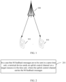
- FIG 1 is a possible schematic structural diagram of a communications system according to an embodiment of this disclosure.
- the communications system includes at least one network device 100 (only one is shown in FIG 1 ) and one or more terminal devices 101 connected to each network device 100.
- the network device 100 may be a base station, a core network device, a transmission and reception point (transmission and reception point, TRP), a relay station, an access point, or the like.
- the network device 100 may be a base transceiver station (base transceiver station, BTS) in global system for mobile communications (global system for mobile communications, GSM) or a code division multiple access (code division multiple access, CDMA) system, may be an NB (NodeB) in a wideband code division multiple access (wideband code division multiple access, WCDMA) system, or may be an eNB or eNodeB (evolved NodeB) in LTE.
- BTS base transceiver station
- GSM global system for mobile communications
- CDMA code division multiple access
- NB NodeB
- WCDMA wideband code division multiple access
- eNodeB evolved NodeB
- the network device 100 may alternatively be a wireless controller in a cloud radio access network (cloud radio access network, CRAN) scenario.
- the network device 100 may alternatively be a network device in a 5G communications system or a network device in a future evolved network.
- the terms do not constitute a limitation on this disclosure.
- the terminal device 101 may be a wireless terminal device or a wired terminal device.
- the wireless terminal device may be a device providing voice and/or other service data connectivity to a user, a handheld device having a wireless communication function, or a computing device having a wireless communication function, or another processing device connected to a wireless modem, an in-vehicle device, or a wearable device connected to a wireless modem, a terminal device in a future 5G network, a terminal device in a future evolved PLMN network in the future, or the like.
- the wireless terminal device may communicate with one or more core networks by using a radio access network (radio access network, RAN).
- radio access network radio access network
- the wireless terminal device may be a mobile terminal device, such as a mobile phone (also referred to as a "cellular" phone) and a computer that is provided with a mobile terminal device, for example, may be a portable mobile apparatus, a pocket-sized mobile apparatus, a handheld mobile apparatus, a computer built-in mobile apparatus, or an in-vehicle mobile apparatus that exchanges voice and/or data with the radio access network, and a device such as a personal communications service (personal communication service, PCS) phone, a cordless telephone set, a session initiation protocol (session initiation protocol, SIP) phone, a wireless local loop (wireless local loop, WLL) station, or a personal digital assistant (personal digital assistant, PDA).
- a personal communications service personal communication service, PCS
- PCS personal communication service
- SIP session initiation protocol
- WLL wireless local loop
- PDA personal digital assistant
- the wireless terminal device may also be a mobile device, user equipment (user equipment, UE), a terminal device, an access terminal device, a wireless communications device, a terminal device unit, a terminal device station, a mobile station (mobile station), a mobile (mobile) console, a remote station (remote station), a remote site, a remote terminal device (remote terminal), a subscriber unit (subscriber unit), a subscriber station (subscriber station), a user agent (user agent), or a terminal device apparatus.
- a terminal device shown in FIG 1 is a mobile phone.
- FIG 2 is a schematic flowchart of a feedback message sending method according to an embodiment of this disclosure. As shown in FIG. 2 , the feedback message sending method provided in this embodiment of this disclosure may include the following steps:
- Step 201 In a case that M feedback messages are to be sent in a same time unit, a terminal device sends an uplink control channel on a target resource in the time unit, where the uplink control channel carries the M feedback messages.
- the target resource is one of N resources, the N resources are resources configured to send feedback messages, the M feedback messages are HARQ feedback messages for a semi-persistent scheduling PDSCH, M is an integer greater than or equal to 2, and N is an integer greater than or equal to M.
- the network device in this embodiment of this disclosure may be a network device in the communications system shown in FIG 1 , for example, a base station; and the terminal device in this embodiment of this disclosure may be a terminal device in the communications system shown in FIG 1 .
- the M feedback messages may be feedback messages for M PDSCHs received by the terminal device at different moments in a same semi-persistent scheduling configuration, or may be feedback messages for M PDSCHs received at a same moment or different moments in different semi-persistent scheduling configurations. This is not specifically limited in this embodiment of this disclosure.
- the N resources are resources configured by the network device for the terminal device to send AN messages.
- the terminal device is configured with a plurality of semi-persistent scheduling manners.
- a plurality of ANs fed back by the terminal device in the same time unit may include feedback messages of a plurality of PDSCHs corresponding to the DL SPS. If DL SPS activated for the terminal device includes DL SPS 1 and DL SPS 2, a plurality of ANs fed back by the terminal device in the same time unit may include feedback messages of a PDSCH of the DL SPS 1 and a PDSCH of the DL SPS 2.
- a plurality of semi-persistent scheduling periods may be partly different, partly the same, all different, or all the same. This is not specifically limited in this embodiment of this disclosure.
- each semi-persistent scheduling period may be less than one time unit, or may be equal to or greater than one time unit.
- the time unit may be one slot (slot) or one sub-slot (sub-slot). This is not specifically limited in this embodiment of this disclosure.
- DL SPS 1, DL SPS 2, and DL SPS 3 are configured in the terminal device. If the DL SPS 1 is activated, after receiving a PDSCH of the DL SPS 1, the terminal device needs to add AN of the PDSCH to a first PUCCH and send the first PUCCH to the network device; if the DL SPS2 is activated, after receiving a PDSCH of the DL SPS 2, the terminal device needs to add AN to a second PUCCH and send the second PUCCH to the network device; or if the DL SPS 3 is activated, after receiving a PDSCH of the DL SPS 3, the terminal device needs to add AN to a third PUCCH and send the third PUCCH to the network device.
- a PUCCH resource for feeding back AN of each PDSCH may be a PUCCH resource configured to feed back the PDSCH of each DL SPS when the network configures the DL SPS 1, the DL SPS 2, and the DL SPS 3, for example, a PUCCH resource configured through a radio resource control (radio resource control, RRC) parameter n1PUCCH-AN corresponding to each DL SPS.
- RRC radio resource control
- the first PUCCH, the second PUCCH, and the third PUCCH are PUCCH resources that are configured by the network device during configuration of the DL SPS 1, the DL SPS 2, and the DL SPS 3 and used to feed back the AN of each PDSCH.
- Formats of the first PUCCH, the second PUCCH, and the third PUCCH may be partly different, partly the same, all different, or all the same. This is not specifically limited in this embodiment of this disclosure.
- Resources used for the first PUCCH, the second PUCCH, and the third PUCCH may be partly different, partly the same, all different, or all the same. This is not specifically limited in this embodiment of this disclosure.
- the M feedback messages include a first feedback message and a second feedback message
- the N resources include a third resource and a fourth resource
- the third resource is a resource configured to send the first feedback message
- the fourth resource is a resource configured to send the second feedback message.
- the target resource is a resource that satisfies a first condition in the third resource and the fourth resource.
- the first condition is any one of the following: (1) a resource for sending a target feedback message; (2) a resource with a smaller symbol length in the third resource and the fourth resource; and (3) a resource with a greater symbol length in the third resource and the fourth resource.
- the target feedback message is a feedback message for a first target shared channel or a feedback message for a second target shared channel;
- the first target shared channel is a downlink shared channel with an earlier receiving time or a downlink shared channel with a later receiving time in a first downlink shared channel and a second downlink shared channel;
- the second target shared channel is a downlink shared channel with a smaller configuration index in the first downlink shared channel and the second downlink shared channel;
- the first downlink shared channel is a downlink shared channel for the first feedback message
- the second downlink shared channel is a downlink shared channel for the second feedback message.
- a capacity of the uplink control channel carrying the M feedback messages is 2 bits.
- a format of the uplink control channel carrying the M feedback messages may be format 0 or format 1.
- a capacity of the uplink control channel carrying the M feedback messages is greater than 2 bits.
- a format of the uplink control channel carrying the M feedback messages may be format 2, format 3, or format 4.
- the terminal device receives one PDSCH in each of two time units.
- the two time units are respectively a time unit n1 and a time unit n2.
- the terminal device receives a first downlink shared channel PDSCH 1 in the time unit n1, adds a first feedback message HARQ-AN 1 of the PDSCH 1 to a first uplink control channel PUCCH 1 in a time unit (n1+k1) that is after the time unit n1, and sends the PUCCH 1; and after receiving a second downlink shared channel PDSCH 2 in the time unit n2, the terminal device needs to add a second feedback message HARQ-AN 2 of the PDSCH 2 to a second uplink control channel PUCCH 2 in the time unit (n2+k2) that is after the time unit n2, and send the PUCCH 2.
- a target resource can be specifically determined in the following manner.
- the resource for the PUCCH 1 configured to carry the HARQ-AN 1 is the third resource, and the resource for the PUCCH 2 carrying the HARQ-AN 2 is the second resource.
- Example 1 Assuming that receiving time n1 of the PDSCH 1 is earlier than receiving time n2 of the PDSCH 2, the first target shared channel is the PDSCH 1, and the target feedback message is a feedback message for the PDSCH 1, namely, the HARQ-AN 1, and the target resource is a resource corresponding to the PUCCH 1.
- Example 2 Assuming that receiving time n1 of the PDSCH 1 is earlier than receiving time n2 of the PDSCH 2, the first target shared channel is the PDSCH 2, and the target feedback message is a feedback message for the PDSCH 2, namely, the HARQ-AN 2, and the target resource is a resource corresponding to the PUCCH 2.
- chronological order of receiving time of the PDSCHs may be defined based on a start symbol or an end symbol of the PDSCH.
- each DL SPS has a corresponding configuration identifier (configuration ID/index), that a configuration identifier of the DL SPS 1 is smaller, and that a configuration identifier of the DL SPS 2 is greater. It can be determined based on values of DL SP identifiers that the second target shared channel is the PDSCH 1 corresponding to the DL SPS 1 with a smaller SPS configuration identifier in PDSCH 1 and PDSCH 2, and the target resource is the resource used by the PUCCH 1.
- Example 4 A symbol length of a resource corresponding to the PUCCH 1 is smaller, a symbol length of a resource corresponding to the PUCCH 2 is greater, and therefore, the target resource is the resource used by the PUCCH 1.
- Example 5 A symbol length of a resource corresponding to the PUCCH 1 is smaller, a symbol length of a resource corresponding to the PUCCH 2 is greater, and therefore, the target resource is the resource used by the PUCCH 1.
- Example 6 A capacity of a PUCCH carrying the HARQ-AN 1 and the HARQ-AN 2 may be 2 bits.
- Example 7 A capacity of a PUCCH carrying the HARQ-AN 1 and the HARQ-AN 2 may be greater than 2 bits.
- the capacity of the PUCCH carrying HARQ-AN 1 and HARQ-AN 2 may be greater than 2 bits
- a bit quantity can be made greater than 2 through padding or repetition.
- the N resources include a first resource and M second resources.
- the first resource is a resource configured to transmit K feedback messages
- each second resource is a resource configured to transmit one of the M feedback messages
- the target resource is the first resource.
- K is a preset integer greater than or equal to M.
- K is a maximum quantity of feedback messages scheduled in a same time unit.
- the first resource can carry the K feedback messages.
- a capacity of the uplink control channel carrying the M feedback messages is equal to 2 bits.
- a format of the uplink control channel carrying the M feedback messages is either of the following: format 0 or format 1.
- a capacity of the uplink control channel carrying the M feedback messages may alternatively be greater than 2 bits.
- a bit quantity can be made greater than 2 through padding or repetition.
- a capacity of the uplink control channel carrying the M feedback messages is greater than 2 bits.
- a format of the uplink control channel carrying the M feedback messages is any one of the following: format 2, format 3, and format 4.
- a resource carrying the K feedback messages may be a first resource corresponding to the PUCCH 3; and the M second resources are the resource corresponding to the PUCCH 1 carrying the HARQ-AN 1 and the resource corresponding to the PUCCH 2 carrying the HARQ-AN 2.
- the terminal device may add the HARQ-AN 1 and the HARQ-AN 2 to the PUCCH 3 of the first resource, and send the PUCCH to the network device.
- the terminal device may alternatively transmit the M feedback messages by using one of the second resources.
- the second resource may be selected as the target resource.
- the method further includes step 202:
- Step 202 The terminal device determines the target resource based on a target factor.
- the target factor includes at least one of the following: (1) a bit quantity of the M feedback messages; (2) a capacity of each resource in the first resource; (3) a start symbol of each resource in the first resource; and (4) a symbol length of each resource in the first resource.
- Example B Based on a total bit quantity of the feedback message that needs to be fed back, the terminal device may determine, as the target resource, a resource from the M second resources that corresponds to a PUCCH capacity greater than or equal to the total bit quantity to be fed back.
- Example C If 2-bit AN information needs to be fed back, the terminal device may select, based on a capacity of each resource in the first resource, a target resource to carry the 2-bit AN information. Different resources in the first resource may be numbered in ascending order of resource capacity. A capacity of a first PUCCH in the first resource is 2 bits, a capacity of a second PUCCH in the first resource is greater than 2 bits, and therefore, the terminal device can determine that a resource corresponding to the first PUCCH is the target resource, that is, the terminal device feeds back the 2-bit AN information on the first PUCCH in the first resource.
- Example D The terminal device may select, as the target resource, a resource with a minimum capacity from a resource with a capacity greater than or equal to M bits in the first resource.
- Different resources in the first resource may be numbered in ascending order of capacity.
- a capacity of a first PUCCH in the first resource is C1 bits
- a capacity of a second PUCCH in the first resource is C2 bits
- a capacity of a third PUCCH in the first resource is C3 bits
- C1 ⁇ C2 ⁇ C3, C1, C2, and C3 are all positive integers.
- the terminal device determines that a resource corresponding to the second PUCCH is the target resource, that is, the terminal device feeds back the M-bit AN information on the resource corresponding to the second PUCCH in the first resource.
- Example E Based on a start symbol of each first resource, the terminal device may select a resource with a smaller start symbol as the target resource, or select a resource with a greater end symbol as the target resource.
- Example F Based on a symbol length of each first resource, the terminal device may select a resource with a greater symbol length as the target resource, or select a resource with a greater end symbol as the target resource.
- Step 203 The terminal device determines a bit sequence of the M feedback messages according to a predetermined rule.
- the terminal device may determine the AN codebook based on at least one of the following: ascending order of receiving time of the PDSCHs, ascending order of configuration identifiers of DL SPS corresponding to PDSCHs/PDCCHs, or ascending order of index numbers of serving cells in which PDSCHs are located.
- the terminal device when the terminal device configures and activates a plurality of DL SPSs on a plurality of serving cells in a serving cell group, the terminal device can determine the codebook in ascending order of the receiving time of the PDSCHs. If a plurality of PDSCHs need to be fed back on a plurality of serving cells in the same time unit, the terminal device can then sort, in ascending order of serving cell index, ANs fed back simultaneously through PDSCHs on the plurality of serving cells.
- a period of the DL SPS is less than one slot, such as 0.5 ms
- two PDSCHs may be transmitted in one slot.
- the terminal device feeds back, in one slot, namely, slot n+k
- the two PDSCHs in the slot according to a related-art solution different PDSCHs correspond to the same n and k.
- a value of k cannot be excessively small. For example, k cannot be 0 or 1. This increases latency of feeding back the AN by the terminal device.
- the terminal device can add the plurality of feedback messages to one uplink control channel for sending, and determine the target resource in which the uplink control channel is located, where the target resource is one of the N resources, and the N resources are the resources configured to send the feedback messages.
- the terminal device can send all the feedback messages to the network device correctly, avoiding that some feedback messages cannot be sent correctly, and reducing unnecessary retransmissions of SPS PDSCH resources.
- the network device may configure, for the terminal device, the target resource for use by the terminal device in the method embodiments.
- An embodiment of this disclosure further provides a feedback message receiving method.
- the method includes the following steps.
- Step 001 A network device receives an uplink control channel on a target resource, where the uplink control channel carries M feedback messages, and the M feedback messages are sent by a terminal device in a same time unit.
- the target resource is one of N resources, the N resources are resources configured to send feedback messages, the M feedback messages are HARQ feedback messages for a semi-persistent scheduling PDSCH, M is an integer greater than or equal to 2, and N is an integer greater than or equal to M.
- the terminal device can add the plurality of feedback messages to one uplink control channel for sending, and determine the target resource in which the uplink control channel is located, where the target resource is one of the N resources, and the N resources are the resources configured to send the feedback messages.
- the terminal device can send all the feedback messages to the network device correctly, avoiding that some feedback messages cannot be sent correctly, and reducing unnecessary retransmissions of SPS PDSCH resources.
- an embodiment of this disclosure provides a terminal device 300, and the terminal device 300 includes a sending module 301.
- the sending module 301 is configured to: in a case that M feedback messages are to be sent in a same time unit, send an uplink control channel on a target resource in the time unit, where the uplink control channel carries the M feedback messages; and the target resource is one of N resources, the N resources are resources configured to send feedback messages, the M feedback messages are HARQ feedback messages for a semi-persistent scheduling PDSCH, M is an integer greater than or equal to 2, and N is an integer greater than or equal to M.
- the M feedback messages include a first feedback message and a second feedback message
- the N resources include a third resource and a fourth resource
- the third resource is a resource configured to send the first feedback message
- the fourth resource is a resource configured to send the second feedback message
- the target resource is a resource that satisfies a first condition in the third resource and the fourth resource.
- the first condition is any one of the following: a resource for sending a target feedback message, a resource with a smaller symbol length in the third resource and the fourth resource, and a resource with a greater symbol length in the third resource and the fourth resource; and the target feedback message is a feedback message for a first target shared channel or a feedback message for a second target shared channel;
- the first target shared channel is a downlink shared channel with an earlier receiving time or a downlink shared channel with a later receiving time in the first downlink shared channel and the second downlink shared channel;
- the second target shared channel is a downlink shared channel with a smaller configuration identifier in the first downlink shared channel and the second downlink shared channel;
- the first downlink shared channel is a downlink shared channel for the first feedback message, and the second downlink shared channel is a downlink shared channel for the second feedback message.
- a capacity of the uplink control channel is 2 bits.
- a format of the uplink control channel is format 0 or format 1.
- the N resources include a first resource and M second resources
- the first resource is a resource configured to transmit K feedback messages
- each second resource is a resource configured to transmit one of the M feedback messages
- the target resource is the first resource
- K is a preset integer greater than or equal to M.
- K is a maximum quantity of feedback messages scheduled in a same time unit.
- a capacity of the uplink control channel is equal to 2 bits; or in a case that M is greater than 2, a capacity of the uplink control channel is greater than 2 bits.
- the terminal device 300 further includes a determining module 302.
- the determining module 302 is configured to: in a case that the first resource includes at least two resources, before the sending module 301 sends the uplink control channel on the target resource in the time unit, determine the target resource based on a target factor, where the target factor includes at least one of the following: a bit quantity of the M feedback messages, a capacity of each resource in the first resource, a start symbol of each resource in the first resource, and a symbol length of each resource in the first resource.
- the terminal device can add the plurality of feedback messages to one uplink control channel for sending, and determine the target resource in which the uplink control channel is located, where the target resource is one of the N resources, and the N resources are the resources configured to send the feedback messages.
- the terminal device can send all the feedback messages to the network device correctly, avoiding that some feedback messages cannot be sent correctly, and reducing unnecessary retransmissions of SPS PDSCH resources.
- FIG 4 is a schematic diagram of a hardware structure of a terminal device for implementing the embodiments of this disclosure.
- the terminal device 400 includes but is not limited to components such as a radio frequency unit 401, a network module 402, an audio output unit 403, an input unit 404, a sensor 405, a display unit 406, a user input unit 407, an interface unit 408, a memory 409, a processor 410, and a power supply 411.
- a person skilled in the art may understand that the terminal device 400 is not limited to the terminal device structure shown in FIG 4 .
- the terminal device 400 may include more or fewer components than those shown in the figure, or combine some of the components, or arrange the components differently.
- the terminal device 400 includes but is not limited to a mobile phone, a tablet computer, a notebook computer, a palmtop computer, an in-vehicle terminal device, a wearable device, a pedometer, and the like.
- the radio frequency unit 401 is configured to: in a case that M feedback messages are to be sent in a same time unit, send an uplink control channel on a target resource in the time unit, where the uplink control channel carries the M feedback messages; and the target resource is one of N resources, the N resources are resources configured to send feedback messages, the M feedback messages are HARQ feedback messages for a semi-persistent scheduling PDSCH, M is an integer greater than or equal to 2, and N is an integer greater than or equal to M.
- the terminal device can add the plurality of feedback messages to one uplink control channel for sending, and determine the target resource in which the uplink control channel is located, where the target resource is one of the N resources, and the N resources are the resources configured to send the feedback messages.
- the terminal device can send all the feedback messages to the network device correctly, avoiding that some feedback messages cannot be sent correctly, and reducing unnecessary retransmissions of SPS PDSCH resources.
- the radio frequency unit 401 may be configured to receive and send signals in an information reception or transmission or call process. Specifically, after receiving downlink data from a base station, the radio frequency unit 401 sends the downlink data to the processor 410 for processing, and in addition, sends uplink data to the base station.
- the radio frequency unit 401 includes but is not limited to an antenna, at least one amplifier, a transceiver, a coupler, a low noise amplifier, a duplexer, and the like.
- the radio frequency unit 401 may further communicate with a network and another device through a wireless communications system.
- the audio output unit 403 may convert audio data received by the radio frequency unit 401 or the network module 402 or stored in the memory 409 into an audio signal and output the audio signal as a sound.
- the audio output unit 403 may further provide an audio output (for example, a call signal reception sound or a message reception sound) related to a specific function performed by the terminal device 400.
- the audio output unit 403 includes a speaker, a buzzer, a telephone receiver, and the like.
- the terminal device 400 further includes at least one sensor 405, for example, an optical sensor, a motion sensor, and other sensors.
- the optical sensor includes an ambient light sensor and a proximity sensor.
- the ambient light sensor may adjust luminance of a display panel 4061 based on brightness of ambient light.
- the proximity sensor may turn off the display panel 4061 and/or backlight when the terminal device 400 moves to an ear.
- an accelerometer sensor can detect magnitudes of accelerations in all directions (usually three axes), can detect a magnitude and a direction of gravity when the terminal device is in a static state, and can be applied to posture recognition (such as screen switching between portrait and landscape, related games, and magnetometer posture calibration) of the terminal device, functions related to vibration recognition (such as pedometer and tapping), and the like.
- the sensor 405 may also include a fingerprint sensor, a pressure sensor, an iris sensor, a molecular sensor, a gyroscope, a barometer, a hygrometer, a thermometer, an infrared sensor, and the like. Details are not described herein.
- the user input unit 407 may be configured to receive input digit or character information, and generate a key signal input related to a user setting and function control of the terminal device 400.
- the user input unit 407 includes a touch panel 4071 and other input devices 4072.
- the touch panel 4071 also referred to as a touchscreen, may capture a touch operation performed by a user on or near the touch panel (for example, an operation performed by the user on the touch panel 4071 or near the touch panel 4071 by using any appropriate object or accessory such as a finger or a stylus).
- the touch panel 4071 may include two parts: a touch detection apparatus and a touch controller.
- the touch detection apparatus detects a touch direction of the user, detects a signal carried by a touch operation, and transmits the signal to the touch controller.
- the touch controller receives touch information from the touch detection apparatus, converts the touch information to point coordinates, and sends the point coordinates to the processor 410, and receives and executes a command sent by the processor 410.
- the touch panel 4071 may be implemented in a plurality of forms, for example, as a resistive, capacitive, infrared, or surface acoustic wave touch panel.
- the user input unit 407 may further include other input devices 4072 in addition to the touch panel 4071.
- the touch panel 4071 may cover the display panel 4061. After detecting a touch operation on or near the touch panel 4071, the touch panel 4071 transmits the touch operation to the processor 410 to determine a type of a touch event. Then the processor 410 provides corresponding visual output on the display panel 4061 based on the type of the touch event.
- the touch panel 4071 and the display panel 4061 are used as two separate components to implement input and output functions of the terminal device 400 in FIG. 4 , the touch panel 4071 and the display panel 4061 may be integrated to implement the input and output functions of the terminal device 400 in some embodiments. This is not specifically limited herein.
- the interface unit 408 is an interface for connecting an external apparatus to the terminal device 400.
- the external apparatus may include a wired or wireless headphone port, an external power supply (or battery charger) port, a wired or wireless data port, a memory card port, a port for connecting an apparatus with an identification module, an audio input/output (I/O) port, a video I/O port, a headset port, or the like.
- the interface unit 408 may be configured to receive an input (for example, data information or power) from an external apparatus, and transmit the received input to one or more components in the terminal device 400, or may be configured to transmit data between the terminal device 400 device and an external apparatus.
- the memory 409 may be configured to store a software program and various data.
- the memory 409 may mainly include a program storage area and a data storage area.
- the program storage area may store an operating system, an application program required for at least one function (such as a sound play function and an image play function), and the like.
- the data storage area may store data (such as audio data and a phone book) created based on use of a mobile phone, and the like.
- the memory 409 may include a high-speed random access memory, or may include a non-volatile memory, for example, at least one magnetic disk storage device, a flash memory device, or other volatile solid-state storage devices.
- the terminal device 400 may further include the power supply 411 (for example, a battery) supplying power to all components.
- the power supply 411 may be logically connected to the processor 410 through a power management system. In this way, functions such as charge management, discharge management, and power consumption management are implemented by using the power management system.
- the terminal device 400 includes some functional modules that are not illustrated. Details are not described herein.
- the terminal device can send an uplink control channel carrying the plurality of feedback messages on the target resource, where the target resource is one of the N resources, and the N resources are the resources configured to send the feedback messages; and the network device receives the uplink control channel.
- the network device can correctly receive all the feedback messages, avoiding that some feedback messages cannot be sent correctly, and reducing unnecessary retransmissions of SPS PDSCH resources.
- a bus architecture may include any quantity of interconnected buses and bridges, and specifically connect together various circuits of one or more processors represented by the processor 501 and a memory represented by the memory 503.
- the bus architecture may further interconnect various other circuits such as a peripheral device, a voltage regulator, and a power management circuit. These are all well known in the art, and therefore are not further described in this specification.
- the bus interface provides an interface.
- the transceiver 502 may be a plurality of elements, including a transmitter and a receiver, and provides units configured to perform communication with various other apparatuses over a transmission medium.
- the user interface 504 may also be an interface for externally or internally connecting a required device, and the connected device includes but is not limited to a mini keyboard, a display, a speaker, a microphone, a joystick, or the like.
- the processor 501 is responsible for management of the bus architecture and general processing, and the memory 503 may store data used by the processor 501 when the processor 501 performs an operation.
- the network device 500 includes some functional modules that are not shown, details of which are not described herein.
- an embodiment of this disclosure further provides a terminal device, and the terminal device includes a processor, a memory, and a computer program stored in the memory and capable of running on the processor.
- the computer program is executed by the processor, the processes of the feedback message sending method in the foregoing embodiments are implemented, and a same technical effect can be achieved. To avoid repetition, details are not described again herein.
Landscapes
- Engineering & Computer Science (AREA)
- Signal Processing (AREA)
- Computer Networks & Wireless Communication (AREA)
- Mobile Radio Communication Systems (AREA)
- Detection And Prevention Of Errors In Transmission (AREA)
Claims (9)
- Verfahren zum Senden von Rückkopplungsnachrichten, das auf ein Endgerät angewendet wird, wobei das Verfahren den folgenden Schritt umfasst:in einem Fall, in dem M Rückkopplungsnachrichten in einer gleichen Zeiteinheit zu senden sind, Senden (201) eines Uplink-Steuerkanals auf einer Zielressource in der Zeiteinheit, wobei der Uplink-Steuerkanal die M Rückkopplungsnachrichten trägt;wobei die Zielressource eine von N Ressourcen ist, die N Ressourcen Ressourcen sind, die konfiguriert sind, um Rückkopplungsnachrichten zu senden, die M Rückkopplungsnachrichten Hybrid-Automatisch-Wiederholungsanforderungs-, HARQ-, Rückkopplungsnachrichten für einen semi-persistenten Scheduling-Physical-Downlink-Shared-Channel, PDSCH, sind, die N Ressourcen eine erste Ressource und M zweite Ressourcen aufweisen, die erste Ressource eine Ressource ist, die konfiguriert ist, um K Rückkopplungsnachrichten zu übermitteln, jede zweite Ressource eine Ressource ist, die konfiguriert ist, um eine der M Rückkopplungsnachrichten zu übermitteln, und die Zielressource die erste Ressource ist;wobei K, M jeweils eine ganze Zahl größer oder gleich 2 sind und N eine ganze Zahl größer oder gleich M ist;wobeiK eine voreingestellte ganze Zahl größer oder gleich M ist;dadurch gekennzeichnet, dassin einem Fall, in dem die erste Ressource eine Mehrzahl von Ressourcen aufweist, das Verfahren vor dem Senden (201) eines Uplink-Steuerkanals auf einer Zielressource in der Zeiteinheit ferner den folgenden Schritt umfasst:Bestimmen der Zielressource auf der Grundlage eines Zielfaktors, wobeider Zielfaktor eine Bitmenge der M Rückkopplungsnachrichten, und/oder eine Kapazität jeder Ressource in der ersten Ressource, und/oder ein Startsymbol jeder Ressource in der ersten Ressource und/oder eine Symbollänge jeder Ressource in der ersten Ressource aufweist;wobei das Verfahren ferner den folgenden Schritt umfasst:Bestimmen einer Bitsequenz der M Rückkopplungsnachrichten gemäß einer vorgegebenen Regel, wobeidie vorgegebene Regel mindestens eine der folgenden aufweist: aufsteigende Reihenfolge der Empfangszeit von Downlink-Shared-Kanälen oder Downlink-Steuerkanälen, die den Rückkopplungsnachrichten entsprechen, aufsteigende Reihenfolge von Konfigurationsidentifikatoren, die Downlink-Shared-Kanälen oder Downlink-Steuerkanälen entsprechen, die Rückkopplungsnachrichten entsprechen, und aufsteigende Reihenfolge von Indexnummern von bedienenden Zellen, in denen Downlink-Shared-Kanäle oder Downlink-Steuerkanäle, die Rückkopplungsnachrichten entsprechen, angeordnet sind.
- Verfahren nach Anspruch 1, wobei K eine maximale Anzahl von Rückkopplungsnachrichten ist, die in einer gleichen Zeiteinheit angesetzt sind.
- Verfahren nach Anspruch 1, wobeiin einem Fall, in dem M gleich 2 ist, eine Kapazität des Uplink-Steuerkanals gleich 2 Bit ist; oderin einem Fall, in dem M größer als 2 ist, eine Kapazität des Uplink-Steuerkanals größer als 2 Bit ist.
- Verfahren nach Anspruch 1 oder 3, wobeiin einem Fall, in dem M gleich 2 ist, ein Format des Uplink-Steuerkanals Format 0 oder Format 1 ist; oderin einem Fall, in dem M größer als 2 ist, ein Format des Uplink-Steuerkanals Format 2, Format 3 oder Format 4 ist.
- Endgerät, wobei das Endgerät ein Sendemodul (301) aufweist;wobei das Sendemodul (301) konfiguriert ist, um: in einem Fall, in dem M Rückkopplungsnachrichten in einer gleichen Zeiteinheit zu senden sind, einen Uplink-Steuerkanal auf einer Zielressource in der Zeiteinheit zu senden, wobei der Uplink-Steuerkanal die M Rückkopplungsnachrichten trägt; unddie Zielressource eine von N Ressourcen ist, die N Ressourcen Ressourcen sind, die konfiguriert sind, um Rückkopplungsnachrichten zu senden, die M Rückkopplungsnachrichten Hybrid-Automatisch-Wiederholungsanforderungs-, HARQ-, Rückkopplungsnachrichten für einen semi-persistenten Scheduling-Physical-Downlink-Shared-Channel, PDSCH, sind, die N Ressourcen eine erste Ressource und M zweite Ressourcen aufweisen, die erste Ressource eine Ressource ist, die konfiguriert ist, um K Rückkopplungsnachrichten zu übermitteln, jede zweite Ressource eine Ressource ist, die konfiguriert ist, um eine der M Rückkopplungsnachrichten zu übermitteln, und die Zielressource die erste Ressource ist;wobei K, M jeweils eine ganze Zahl größer als oder gleich 2 sind und N eine ganze Zahl größer als oder gleich M ist;wobeiK eine voreingestellte ganze Zahl größer als oder gleich M ist;dadurch gekennzeichnet, dassdas Endgerät ferner ein Bestimmungsmodul (302) aufweist; unddas Bestimmungsmodul (302) konfiguriert ist, um: in einem Fall, in dem die erste Ressource mindestens zwei Ressourcen aufweist, bevor das Sendemodul (301) den Uplink-Steuerkanal auf der Zielressource in der Zeiteinheit sendet, die Zielressource basierend auf einem Zielfaktor zu bestimmen, wobeider Zielfaktor eine Bitmenge der M Rückkopplungsnachrichten, und/oder eine Kapazität jeder Ressource in der ersten Ressource, und/oder ein Startsymbol jeder Ressource in der ersten Ressource und/oder eine Symbollänge jeder Ressource in der ersten Ressource aufweist;wobei das Bestimmungsmodul (302) ferner konfiguriert ist, um eine Bitsequenz der M Rückkopplungsnachrichten gemäß einer vorgegebenen Regel zu bestimmen, wobeidie vorgegebene Regel mindestens eines der folgenden aufweist: aufsteigende Reihenfolge der Empfangszeit von Downlink-Shared-Kanälen oder Downlink-Steuerkanälen, die Rückkopplungsnachrichten entsprechen, aufsteigende Reihenfolge von Konfigurationsidentifikatoren, die Downlink-Shared-Kanälen oder Downlink-Steuerkanälen entsprechen, die Rückkopplungsnachrichten entsprechen, und aufsteigende Reihenfolge von Indexnummern von bedienenden Zellen, in denen Downlink-Shared-Kanäle oder Downlink-Steuerkanäle, die Rückkopplungsnachrichten entsprechen, angeordnet sind.
- Endgerät nach Anspruch 5, wobei K eine maximale Anzahl von Rückkopplungsnachrichten ist, die in einer gleichen Zeiteinheit angesetzt sind.
- Endgerät nach Anspruch 5, wobeiin einem Fall, in dem M gleich 2 ist, eine Kapazität des Uplink-Steuerkanals gleich 2 Bit ist; oderin einem Fall, in dem M größer als 2 ist, eine Kapazität des Uplink-Steuerkanals größer als 2 Bit ist.
- Endgerät nach Anspruch 5 oder 7, wobeiin einem Fall, in dem M gleich 2 ist, ein Format des Uplink-Steuerkanals Format 0 oder Format 1 ist; oderin einem Fall, in dem M größer als 2 ist, ein Format des Uplink-Steuerkanals Format 2, Format 3 oder Format 4 ist.
- Computerlesbares Speichermedium, wobei das computerlesbare Speichermedium ein Computerprogramm speichert, das, wenn es von einem Prozessor ausgeführt wird, den Prozessor veranlasst, den folgenden Schritt durchzuführen:in einem Fall, in dem M Rückkopplungsnachrichten in einer gleichen Zeiteinheit zu senden sind, Senden eines Uplink-Steuerkanals auf einer Zielressource in der Zeiteinheit, wobei der Uplink-Steuerkanal die M Rückkopplungsnachrichten trägt;wobei die Zielressource eine von N Ressourcen ist, die N Ressourcen Ressourcen sind, die konfiguriert sind, um Rückkopplungsnachrichten zu senden, die M Rückkopplungsnachrichten Hybrid-Automatisch-Wiederholungsanforderungs-, HARQ-, Rückkopplungsnachrichten für einen semi-persistenten Scheduling-Physical-Downlink-Shared-Channel, PDSCH, sind, die N Ressourcen eine erste Ressource und M zweite Ressourcen aufweisen, die erste Ressource eine Ressource ist, die konfiguriert ist, um K Rückkopplungsnachrichten zu übermitteln, jede zweite Ressource eine Ressource ist, die konfiguriert ist, um eine der M Rückkopplungsnachrichten zu übermitteln, und die Zielressource die erste Ressource ist;wobei K, M jeweils eine ganze Zahl größer oder gleich 2 sind und N eine ganze Zahl größer oder gleich M ist, K eine voreingestellte ganze Zahl größer oder gleich M ist;dadurch gekennzeichnet, dassin einem Fall, in dem die erste Ressource eine Mehrzahl von Ressourcen aufweist, vor dem Senden eines Uplink-Steuerkanals auf einer Zielressource in der Zeiteinheit das Computerprogramm von dem Prozessor ausgeführt wird, um ferner den folgenden Schritt zu implementieren:Bestimmen der Zielressource auf der Grundlage eines Zielfaktors, wobeider Zielfaktor eine Bitmenge der M Rückkopplungsnachrichten, und/oder eine Kapazität jeder Ressource in der ersten Ressource, und/oder ein Startsymbol jeder Ressource in der ersten Ressource und/oder eine Symbollänge jeder Ressource in der ersten Ressource aufweist;wobei das Computerprogramm von dem Prozessor ausgeführt wird, um ferner den folgenden Schritt zu implementieren:Bestimmen einer Bitsequenz der M Rückkopplungsnachrichten gemäß einer vorgegebenen Regel, wobeidie vorgegebene Regel mindestens eine der folgenden aufweist: aufsteigende Reihenfolge der Empfangszeit von Downlink-Shared-Kanälen oder Downlink-Steuerkanälen, die Rückkopplungsnachrichten entsprechen, aufsteigende Reihenfolge von Konfigurationsidentifikatoren, die Downlink-Shared-Kanälen oder Downlink-Steuerkanälen entsprechen, die Rückkopplungsnachrichten entsprechen, und aufsteigende Reihenfolge von Indexnummern von bedienenden Zellen, in denen Downlink-Shared-Kanäle oder Downlink-Steuerkanäle, die Rückkopplungsnachrichten entsprechen, angeordnet sind.
Applications Claiming Priority (2)
| Application Number | Priority Date | Filing Date | Title |
|---|---|---|---|
| CN201910365514.XA CN111262663B (zh) | 2019-04-30 | 2019-04-30 | 一种反馈消息的发送方法及终端设备 |
| PCT/CN2020/087543 WO2020221257A1 (zh) | 2019-04-30 | 2020-04-28 | 反馈消息的发送方法及终端设备 |
Publications (3)
| Publication Number | Publication Date |
|---|---|
| EP3965335A1 EP3965335A1 (de) | 2022-03-09 |
| EP3965335A4 EP3965335A4 (de) | 2022-06-08 |
| EP3965335B1 true EP3965335B1 (de) | 2025-03-26 |
Family
ID=70950696
Family Applications (1)
| Application Number | Title | Priority Date | Filing Date |
|---|---|---|---|
| EP20799502.8A Active EP3965335B1 (de) | 2019-04-30 | 2020-04-28 | Verfahren zum senden einer rückkopplungsnachricht und endgerät |
Country Status (11)
| Country | Link |
|---|---|
| US (1) | US12068863B2 (de) |
| EP (1) | EP3965335B1 (de) |
| JP (1) | JP7332715B2 (de) |
| KR (1) | KR102686949B1 (de) |
| CN (1) | CN111262663B (de) |
| BR (1) | BR112021021800A2 (de) |
| ES (1) | ES3024360T3 (de) |
| HU (1) | HUE071133T2 (de) |
| PT (1) | PT3965335T (de) |
| SG (1) | SG11202112050UA (de) |
| WO (1) | WO2020221257A1 (de) |
Families Citing this family (14)
| Publication number | Priority date | Publication date | Assignee | Title |
|---|---|---|---|---|
| CN113891394B (zh) * | 2020-07-01 | 2024-09-13 | 华为技术有限公司 | 一种harq-ack传输方法和装置 |
| CN113949492B (zh) * | 2020-07-16 | 2023-06-06 | 维沃移动通信有限公司 | 反馈信息传输方法、装置、终端及网络侧设备 |
| CN114071501A (zh) * | 2020-08-05 | 2022-02-18 | 维沃移动通信有限公司 | 下行传输方法、下行传输装置、终端及网络侧设备 |
| WO2022027605A1 (zh) * | 2020-08-07 | 2022-02-10 | 华为技术有限公司 | 信息传输方法和通信装置 |
| CN116982277A (zh) * | 2020-10-08 | 2023-10-31 | 紫藤科技有限公司 | Harq处理方法、用户设备和基站 |
| CN115066848B (zh) * | 2020-12-31 | 2024-08-23 | 北京小米移动软件有限公司 | Harq反馈信息的发送方法、装置及通信设备 |
| CN112910610B (zh) * | 2021-01-15 | 2022-05-24 | 中国信息通信研究院 | 一种混合自动重传请求应答方法和设备 |
| CN115189819B (zh) * | 2021-04-01 | 2023-11-21 | 维沃移动通信有限公司 | 确定pucch资源的方法、装置及终端 |
| EP4322437A4 (de) * | 2021-04-09 | 2024-05-29 | Beijing Xiaomi Mobile Software Co., Ltd. | Verfahren zur bestimmung eines harq-codebuchs, verfahren zum empfangen von harq-rückkopplungsinformationen und vorrichtung dafür |
| WO2022222144A1 (zh) * | 2021-04-23 | 2022-10-27 | 北京小米移动软件有限公司 | 混合自动重传请求harq的传输方法、装置及通信设备 |
| CN115314842B (zh) * | 2021-05-07 | 2024-06-14 | 展讯通信(上海)有限公司 | 信息分享方法及装置、接入点设备、用户设备 |
| CN115604848A (zh) * | 2021-07-09 | 2023-01-13 | 维沃移动通信有限公司(Cn) | Pucch时域资源重叠的处理方法及装置 |
| CN116744461A (zh) * | 2022-03-01 | 2023-09-12 | 荣耀终端有限公司 | 半静态调度方法、用户设备、基站及通信系统 |
| CN115802458B (zh) * | 2022-11-07 | 2025-10-17 | 中国信息通信研究院 | 一种无线通信系统信息传输方法和设备 |
Family Cites Families (22)
| Publication number | Priority date | Publication date | Assignee | Title |
|---|---|---|---|---|
| CN102468945B (zh) * | 2010-11-03 | 2014-09-10 | 大唐移动通信设备有限公司 | Ack/nack反馈信息的传输方法和设备 |
| JP6090437B2 (ja) | 2012-06-18 | 2017-03-08 | 富士通株式会社 | チャネル状態情報をフィードバックする方法、ユーザ装置及びシステム |
| WO2014014254A1 (ko) * | 2012-07-16 | 2014-01-23 | 엘지전자 주식회사 | 무선통신 시스템에서 수신확인 전송 방법 및 장치 |
| CN110350951B (zh) * | 2012-08-03 | 2023-11-24 | 德克萨斯仪器股份有限公司 | 用于协作多点通信的上行链路信令 |
| US10291372B2 (en) * | 2014-11-03 | 2019-05-14 | Qualcomm Incorporated | Hybrid automatic repeat/request (HARQ) scheduling |
| CN105991179A (zh) * | 2015-03-04 | 2016-10-05 | 华为技术有限公司 | 传输信道状态信息的方法和装置 |
| US10342005B2 (en) * | 2015-08-14 | 2019-07-02 | Telefonaktiebolaget Lm Ericsson (Publ) | Methods for determining a HARQ-ACK codebook size for a user equipment and base station |
| CN107231218B (zh) * | 2016-03-25 | 2021-07-30 | 大唐移动通信设备有限公司 | 一种ack/nack反馈方法及相关设备 |
| EP3451768B1 (de) | 2016-04-26 | 2022-05-04 | Sharp Kabushiki Kaisha | Endgerätevorrichtung, basisstationsvorrichtung, kommunikationsverfahren und integrierte schaltung |
| CN107566097B (zh) * | 2016-06-30 | 2020-12-25 | 展讯通信(上海)有限公司 | 用户设备及下行数据的harq反馈方法 |
| WO2018010077A1 (zh) * | 2016-07-11 | 2018-01-18 | 广东欧珀移动通信有限公司 | 传输数据的方法和终端设备 |
| CN107733574A (zh) * | 2016-08-11 | 2018-02-23 | 北京信威通信技术股份有限公司 | 一种设备到设备通信的反馈方法及装置 |
| MX2019007209A (es) * | 2016-12-26 | 2019-08-16 | Guangdong Oppo Mobile Telecommunications Corp Ltd | Procedimiento de comunicaciones inalambricas, dispositivo de red y dispositivo terminal. |
| CN108289015B (zh) * | 2017-01-09 | 2023-04-07 | 北京三星通信技术研究有限公司 | 发送harq-ack/nack的方法和设备及下行传输方法和设备 |
| KR20190113919A (ko) * | 2017-02-10 | 2019-10-08 | 후아웨이 테크놀러지 컴퍼니 리미티드 | 데이터 전송 방법, 관련 장치, 및 시스템 |
| CN120692671A (zh) * | 2017-03-24 | 2025-09-23 | 北京三星通信技术研究有限公司 | 半静态资源调度方法、功率控制方法及相应用户设备 |
| CN108809524B (zh) * | 2017-04-28 | 2021-04-09 | 华为技术有限公司 | 传输反馈信息的方法和装置 |
| CN109152007B (zh) * | 2017-06-15 | 2021-06-29 | 华为技术有限公司 | 一种控制信息发送、接收方法及装置 |
| WO2019066630A1 (en) * | 2017-09-29 | 2019-04-04 | Samsung Electronics Co., Ltd. | UPLINK TRANSMISSION METHOD AND CORRESPONDING EQUIPMENT |
| US10715283B2 (en) * | 2017-10-02 | 2020-07-14 | Kt Corporation | Apparatus and method of transmitting and receiving HARQ ACK/NACK information for new radio |
| WO2020029132A1 (zh) | 2018-08-08 | 2020-02-13 | 北京小米移动软件有限公司 | 混合自动重传请求harq反馈方法及装置 |
| CN113574820B (zh) * | 2019-03-22 | 2024-04-26 | 联想(新加坡)私人有限公司 | 聚合harq反馈 |
-
2019
- 2019-04-30 CN CN201910365514.XA patent/CN111262663B/zh active Active
-
2020
- 2020-04-28 HU HUE20799502A patent/HUE071133T2/hu unknown
- 2020-04-28 JP JP2021564545A patent/JP7332715B2/ja active Active
- 2020-04-28 PT PT207995028T patent/PT3965335T/pt unknown
- 2020-04-28 WO PCT/CN2020/087543 patent/WO2020221257A1/zh not_active Ceased
- 2020-04-28 BR BR112021021800A patent/BR112021021800A2/pt unknown
- 2020-04-28 SG SG11202112050UA patent/SG11202112050UA/en unknown
- 2020-04-28 EP EP20799502.8A patent/EP3965335B1/de active Active
- 2020-04-28 ES ES20799502T patent/ES3024360T3/es active Active
- 2020-04-28 KR KR1020217038797A patent/KR102686949B1/ko active Active
-
2021
- 2021-10-28 US US17/512,881 patent/US12068863B2/en active Active
Also Published As
| Publication number | Publication date |
|---|---|
| EP3965335A4 (de) | 2022-06-08 |
| HUE071133T2 (hu) | 2025-08-28 |
| PT3965335T (pt) | 2025-04-21 |
| ES3024360T3 (en) | 2025-06-04 |
| US12068863B2 (en) | 2024-08-20 |
| WO2020221257A1 (zh) | 2020-11-05 |
| JP7332715B2 (ja) | 2023-08-23 |
| SG11202112050UA (en) | 2021-12-30 |
| US20220052799A1 (en) | 2022-02-17 |
| BR112021021800A2 (pt) | 2021-12-28 |
| KR102686949B1 (ko) | 2024-07-19 |
| CN111262663B (zh) | 2021-08-31 |
| JP2022530902A (ja) | 2022-07-04 |
| EP3965335A1 (de) | 2022-03-09 |
| CN111262663A (zh) | 2020-06-09 |
| KR20220002533A (ko) | 2022-01-06 |
Similar Documents
| Publication | Publication Date | Title |
|---|---|---|
| EP3965335B1 (de) | Verfahren zum senden einer rückkopplungsnachricht und endgerät | |
| US12113622B2 (en) | Method for feedback control, UE, and network device | |
| US20220132496A1 (en) | Uci transmission method, uci receiving method, terminal, and network device | |
| CN113573256B (zh) | 信息反馈、资源调度方法、终端及网络设备 | |
| US12149481B2 (en) | Hybrid automatic repeat request-acknowledgement (HARQ-ACK) feedback position determining method and communications device | |
| US11546091B2 (en) | Method for determining HARQ-ACK codebook and user equipment | |
| US12058684B2 (en) | Resource configuration method, resource determining method, network side device and terminal | |
| EP3855662A1 (de) | Ressourcenkonfigurationsverfahren, endgerät und netzwerkvorrichtung | |
| WO2020119243A1 (zh) | 物理上行控制信道传输方法、网络侧设备和终端 | |
| US20230050298A1 (en) | Resource determining method, resource indication method, and device | |
| CN110890943A (zh) | 确定方法、终端设备及网络设备 | |
| US12501441B2 (en) | DAI counting method, DAI counting control method, terminal, and network device | |
| EP4096130A1 (de) | Meldeverfahren für kanalzustandsinformationen (csi), endgerät und computerlesbares speichermedium | |
| WO2019214420A1 (zh) | 业务调度方法、终端及网络设备 | |
| CN113473610B (zh) | 一种反馈方法及设备 | |
| JP7564884B2 (ja) | 情報伝送方法及び機器 | |
| HK40061260B (en) | Method for sending feedback message, and terminal device | |
| HK40061260A (en) | Method for sending feedback message, and terminal device | |
| HK40081958A (en) | Dai counting method, dai counting control method, terminal and network device | |
| HK40061259B (en) | Uplink control information sending and receiving methods, terminal, and network side device |
Legal Events
| Date | Code | Title | Description |
|---|---|---|---|
| STAA | Information on the status of an ep patent application or granted ep patent |
Free format text: STATUS: THE INTERNATIONAL PUBLICATION HAS BEEN MADE |
|
| PUAI | Public reference made under article 153(3) epc to a published international application that has entered the european phase |
Free format text: ORIGINAL CODE: 0009012 |
|
| STAA | Information on the status of an ep patent application or granted ep patent |
Free format text: STATUS: REQUEST FOR EXAMINATION WAS MADE |
|
| 17P | Request for examination filed |
Effective date: 20211112 |
|
| AK | Designated contracting states |
Kind code of ref document: A1 Designated state(s): AL AT BE BG CH CY CZ DE DK EE ES FI FR GB GR HR HU IE IS IT LI LT LU LV MC MK MT NL NO PL PT RO RS SE SI SK SM TR |
|
| REG | Reference to a national code |
Ref country code: HK Ref legal event code: DE Ref document number: 40061260 Country of ref document: HK |
|
| A4 | Supplementary search report drawn up and despatched |
Effective date: 20220509 |
|
| RIC1 | Information provided on ipc code assigned before grant |
Ipc: H04L 5/00 20060101ALI20220502BHEP Ipc: H04L 1/18 20060101AFI20220502BHEP |
|
| DAV | Request for validation of the european patent (deleted) | ||
| DAX | Request for extension of the european patent (deleted) | ||
| STAA | Information on the status of an ep patent application or granted ep patent |
Free format text: STATUS: EXAMINATION IS IN PROGRESS |
|
| 17Q | First examination report despatched |
Effective date: 20240117 |
|
| GRAP | Despatch of communication of intention to grant a patent |
Free format text: ORIGINAL CODE: EPIDOSNIGR1 |
|
| STAA | Information on the status of an ep patent application or granted ep patent |
Free format text: STATUS: GRANT OF PATENT IS INTENDED |
|
| INTG | Intention to grant announced |
Effective date: 20241114 |
|
| GRAS | Grant fee paid |
Free format text: ORIGINAL CODE: EPIDOSNIGR3 |
|
| GRAA | (expected) grant |
Free format text: ORIGINAL CODE: 0009210 |
|
| STAA | Information on the status of an ep patent application or granted ep patent |
Free format text: STATUS: THE PATENT HAS BEEN GRANTED |
|
| AK | Designated contracting states |
Kind code of ref document: B1 Designated state(s): AL AT BE BG CH CY CZ DE DK EE ES FI FR GB GR HR HU IE IS IT LI LT LU LV MC MK MT NL NO PL PT RO RS SE SI SK SM TR |
|
| REG | Reference to a national code |
Ref country code: GB Ref legal event code: FG4D |
|
| REG | Reference to a national code |
Ref country code: CH Ref legal event code: EP |
|
| REG | Reference to a national code |
Ref country code: DE Ref legal event code: R096 Ref document number: 602020048396 Country of ref document: DE |
|
| REG | Reference to a national code |
Ref country code: PT Ref legal event code: SC4A Ref document number: 3965335 Country of ref document: PT Date of ref document: 20250421 Kind code of ref document: T Free format text: AVAILABILITY OF NATIONAL TRANSLATION Effective date: 20250414 |
|
| REG | Reference to a national code |
Ref country code: IE Ref legal event code: FG4D |
|
| REG | Reference to a national code |
Ref country code: NL Ref legal event code: FP |
|
| REG | Reference to a national code |
Ref country code: ES Ref legal event code: FG2A Ref document number: 3024360 Country of ref document: ES Kind code of ref document: T3 Effective date: 20250604 |
|
| PG25 | Lapsed in a contracting state [announced via postgrant information from national office to epo] |
Ref country code: RS Free format text: LAPSE BECAUSE OF FAILURE TO SUBMIT A TRANSLATION OF THE DESCRIPTION OR TO PAY THE FEE WITHIN THE PRESCRIBED TIME-LIMIT Effective date: 20250626 |
|
| PG25 | Lapsed in a contracting state [announced via postgrant information from national office to epo] |
Ref country code: FI Free format text: LAPSE BECAUSE OF FAILURE TO SUBMIT A TRANSLATION OF THE DESCRIPTION OR TO PAY THE FEE WITHIN THE PRESCRIBED TIME-LIMIT Effective date: 20250326 |
|
| PGFP | Annual fee paid to national office [announced via postgrant information from national office to epo] |
Ref country code: DE Payment date: 20250325 Year of fee payment: 6 |
|
| PGFP | Annual fee paid to national office [announced via postgrant information from national office to epo] |
Ref country code: ES Payment date: 20250509 Year of fee payment: 6 |
|
| REG | Reference to a national code |
Ref country code: LT Ref legal event code: MG9D |
|
| PG25 | Lapsed in a contracting state [announced via postgrant information from national office to epo] |
Ref country code: NO Free format text: LAPSE BECAUSE OF FAILURE TO SUBMIT A TRANSLATION OF THE DESCRIPTION OR TO PAY THE FEE WITHIN THE PRESCRIBED TIME-LIMIT Effective date: 20250626 |
|
| PGFP | Annual fee paid to national office [announced via postgrant information from national office to epo] |
Ref country code: HU Payment date: 20250415 Year of fee payment: 6 |
|
| PG25 | Lapsed in a contracting state [announced via postgrant information from national office to epo] |
Ref country code: HR Free format text: LAPSE BECAUSE OF FAILURE TO SUBMIT A TRANSLATION OF THE DESCRIPTION OR TO PAY THE FEE WITHIN THE PRESCRIBED TIME-LIMIT Effective date: 20250326 |
|
| PG25 | Lapsed in a contracting state [announced via postgrant information from national office to epo] |
Ref country code: LV Free format text: LAPSE BECAUSE OF FAILURE TO SUBMIT A TRANSLATION OF THE DESCRIPTION OR TO PAY THE FEE WITHIN THE PRESCRIBED TIME-LIMIT Effective date: 20250326 |
|
| PGFP | Annual fee paid to national office [announced via postgrant information from national office to epo] |
Ref country code: PT Payment date: 20250424 Year of fee payment: 6 |
|
| PG25 | Lapsed in a contracting state [announced via postgrant information from national office to epo] |
Ref country code: GR Free format text: LAPSE BECAUSE OF FAILURE TO SUBMIT A TRANSLATION OF THE DESCRIPTION OR TO PAY THE FEE WITHIN THE PRESCRIBED TIME-LIMIT Effective date: 20250627 Ref country code: BG Free format text: LAPSE BECAUSE OF FAILURE TO SUBMIT A TRANSLATION OF THE DESCRIPTION OR TO PAY THE FEE WITHIN THE PRESCRIBED TIME-LIMIT Effective date: 20250326 |
|
| REG | Reference to a national code |
Ref country code: HU Ref legal event code: AG4A Ref document number: E071133 Country of ref document: HU |
|
| PG25 | Lapsed in a contracting state [announced via postgrant information from national office to epo] |
Ref country code: SE Free format text: LAPSE BECAUSE OF FAILURE TO SUBMIT A TRANSLATION OF THE DESCRIPTION OR TO PAY THE FEE WITHIN THE PRESCRIBED TIME-LIMIT Effective date: 20250326 |
|
| REG | Reference to a national code |
Ref country code: AT Ref legal event code: MK05 Ref document number: 1780023 Country of ref document: AT Kind code of ref document: T Effective date: 20250326 |
|
| PG25 | Lapsed in a contracting state [announced via postgrant information from national office to epo] |
Ref country code: SM Free format text: LAPSE BECAUSE OF FAILURE TO SUBMIT A TRANSLATION OF THE DESCRIPTION OR TO PAY THE FEE WITHIN THE PRESCRIBED TIME-LIMIT Effective date: 20250326 |
|
| PG25 | Lapsed in a contracting state [announced via postgrant information from national office to epo] |
Ref country code: PL Free format text: LAPSE BECAUSE OF FAILURE TO SUBMIT A TRANSLATION OF THE DESCRIPTION OR TO PAY THE FEE WITHIN THE PRESCRIBED TIME-LIMIT Effective date: 20250326 |
|
| PG25 | Lapsed in a contracting state [announced via postgrant information from national office to epo] |
Ref country code: AT Free format text: LAPSE BECAUSE OF FAILURE TO SUBMIT A TRANSLATION OF THE DESCRIPTION OR TO PAY THE FEE WITHIN THE PRESCRIBED TIME-LIMIT Effective date: 20250326 |
|
| PG25 | Lapsed in a contracting state [announced via postgrant information from national office to epo] |
Ref country code: EE Free format text: LAPSE BECAUSE OF FAILURE TO SUBMIT A TRANSLATION OF THE DESCRIPTION OR TO PAY THE FEE WITHIN THE PRESCRIBED TIME-LIMIT Effective date: 20250326 |
|
| PG25 | Lapsed in a contracting state [announced via postgrant information from national office to epo] |
Ref country code: RO Free format text: LAPSE BECAUSE OF FAILURE TO SUBMIT A TRANSLATION OF THE DESCRIPTION OR TO PAY THE FEE WITHIN THE PRESCRIBED TIME-LIMIT Effective date: 20250326 |
|
| PG25 | Lapsed in a contracting state [announced via postgrant information from national office to epo] |
Ref country code: SK Free format text: LAPSE BECAUSE OF FAILURE TO SUBMIT A TRANSLATION OF THE DESCRIPTION OR TO PAY THE FEE WITHIN THE PRESCRIBED TIME-LIMIT Effective date: 20250326 |
|
| PG25 | Lapsed in a contracting state [announced via postgrant information from national office to epo] |
Ref country code: IS Free format text: LAPSE BECAUSE OF FAILURE TO SUBMIT A TRANSLATION OF THE DESCRIPTION OR TO PAY THE FEE WITHIN THE PRESCRIBED TIME-LIMIT Effective date: 20250726 |
|
| REG | Reference to a national code |
Ref country code: CH Ref legal event code: H13 Free format text: ST27 STATUS EVENT CODE: U-0-0-H10-H13 (AS PROVIDED BY THE NATIONAL OFFICE) Effective date: 20251125 |
|
| PG25 | Lapsed in a contracting state [announced via postgrant information from national office to epo] |
Ref country code: LU Free format text: LAPSE BECAUSE OF NON-PAYMENT OF DUE FEES Effective date: 20250428 |
|
| PG25 | Lapsed in a contracting state [announced via postgrant information from national office to epo] |
Ref country code: MC Free format text: LAPSE BECAUSE OF FAILURE TO SUBMIT A TRANSLATION OF THE DESCRIPTION OR TO PAY THE FEE WITHIN THE PRESCRIBED TIME-LIMIT Effective date: 20250326 |
|
| REG | Reference to a national code |
Ref country code: BE Ref legal event code: MM Effective date: 20250430 |
|
| REG | Reference to a national code |
Ref country code: DE Ref legal event code: R097 Ref document number: 602020048396 Country of ref document: DE |
|
| PG25 | Lapsed in a contracting state [announced via postgrant information from national office to epo] |
Ref country code: DK Free format text: LAPSE BECAUSE OF FAILURE TO SUBMIT A TRANSLATION OF THE DESCRIPTION OR TO PAY THE FEE WITHIN THE PRESCRIBED TIME-LIMIT Effective date: 20250326 |
|
| PG25 | Lapsed in a contracting state [announced via postgrant information from national office to epo] |
Ref country code: BE Free format text: LAPSE BECAUSE OF NON-PAYMENT OF DUE FEES Effective date: 20250430 |
|
| PG25 | Lapsed in a contracting state [announced via postgrant information from national office to epo] |
Ref country code: CH Free format text: LAPSE BECAUSE OF NON-PAYMENT OF DUE FEES Effective date: 20250430 |
|
| PG25 | Lapsed in a contracting state [announced via postgrant information from national office to epo] |
Ref country code: CZ Free format text: LAPSE BECAUSE OF FAILURE TO SUBMIT A TRANSLATION OF THE DESCRIPTION OR TO PAY THE FEE WITHIN THE PRESCRIBED TIME-LIMIT Effective date: 20250326 |
|
| PLBE | No opposition filed within time limit |
Free format text: ORIGINAL CODE: 0009261 |
|
| STAA | Information on the status of an ep patent application or granted ep patent |
Free format text: STATUS: NO OPPOSITION FILED WITHIN TIME LIMIT |
|
| REG | Reference to a national code |
Ref country code: CH Ref legal event code: L10 Free format text: ST27 STATUS EVENT CODE: U-0-0-L10-L00 (AS PROVIDED BY THE NATIONAL OFFICE) Effective date: 20260211 |
|
| 26N | No opposition filed |
Effective date: 20260105 |
|
| PGFP | Annual fee paid to national office [announced via postgrant information from national office to epo] |
Ref country code: GB Payment date: 20260312 Year of fee payment: 7 |
|
| PG25 | Lapsed in a contracting state [announced via postgrant information from national office to epo] |
Ref country code: IE Free format text: LAPSE BECAUSE OF NON-PAYMENT OF DUE FEES Effective date: 20250428 |
|
| PGFP | Annual fee paid to national office [announced via postgrant information from national office to epo] |
Ref country code: IT Payment date: 20260320 Year of fee payment: 7 |
|
| PGFP | Annual fee paid to national office [announced via postgrant information from national office to epo] |
Ref country code: NL Payment date: 20260317 Year of fee payment: 7 |
|
| PGFP | Annual fee paid to national office [announced via postgrant information from national office to epo] |
Ref country code: FR Payment date: 20260309 Year of fee payment: 7 |