EP3965246B1 - Verfahren zur identifizierung eines transformatorbereichs und computerlesbares speichermedium - Google Patents
Verfahren zur identifizierung eines transformatorbereichs und computerlesbares speichermedium Download PDFInfo
- Publication number
- EP3965246B1 EP3965246B1 EP20798782.7A EP20798782A EP3965246B1 EP 3965246 B1 EP3965246 B1 EP 3965246B1 EP 20798782 A EP20798782 A EP 20798782A EP 3965246 B1 EP3965246 B1 EP 3965246B1
- Authority
- EP
- European Patent Office
- Prior art keywords
- domain
- power
- state
- identified
- electric meter
- Prior art date
- Legal status (The legal status is an assumption and is not a legal conclusion. Google has not performed a legal analysis and makes no representation as to the accuracy of the status listed.)
- Active
Links
Images


Classifications
-
- G—PHYSICS
- G01—MEASURING; TESTING
- G01R—MEASURING ELECTRIC VARIABLES; MEASURING MAGNETIC VARIABLES
- G01R22/00—Arrangements for measuring time integral of electric power or current, e.g. electricity meters
- G01R22/06—Arrangements for measuring time integral of electric power or current, e.g. electricity meters by electronic methods
- G01R22/061—Details of electronic electricity meters
-
- G—PHYSICS
- G01—MEASURING; TESTING
- G01R—MEASURING ELECTRIC VARIABLES; MEASURING MAGNETIC VARIABLES
- G01R21/00—Arrangements for measuring electric power or power factor
- G01R21/133—Arrangements for measuring electric power or power factor by using digital technique
-
- G—PHYSICS
- G01—MEASURING; TESTING
- G01R—MEASURING ELECTRIC VARIABLES; MEASURING MAGNETIC VARIABLES
- G01R19/00—Arrangements for measuring currents or voltages or for indicating presence or sign thereof
- G01R19/25—Arrangements for measuring currents or voltages or for indicating presence or sign thereof using digital measurement techniques
- G01R19/2513—Arrangements for monitoring electric power systems, e.g. power lines or loads; Logging
-
- G—PHYSICS
- G01—MEASURING; TESTING
- G01R—MEASURING ELECTRIC VARIABLES; MEASURING MAGNETIC VARIABLES
- G01R22/00—Arrangements for measuring time integral of electric power or current, e.g. electricity meters
- G01R22/06—Arrangements for measuring time integral of electric power or current, e.g. electricity meters by electronic methods
- G01R22/061—Details of electronic electricity meters
- G01R22/063—Details of electronic electricity meters related to remote communication
-
- G—PHYSICS
- G01—MEASURING; TESTING
- G01R—MEASURING ELECTRIC VARIABLES; MEASURING MAGNETIC VARIABLES
- G01R22/00—Arrangements for measuring time integral of electric power or current, e.g. electricity meters
- G01R22/06—Arrangements for measuring time integral of electric power or current, e.g. electricity meters by electronic methods
- G01R22/10—Arrangements for measuring time integral of electric power or current, e.g. electricity meters by electronic methods using digital techniques
-
- H—ELECTRICITY
- H02—GENERATION; CONVERSION OR DISTRIBUTION OF ELECTRIC POWER
- H02J—CIRCUIT ARRANGEMENTS OR SYSTEMS FOR SUPPLYING OR DISTRIBUTING ELECTRIC POWER; SYSTEMS FOR STORING ELECTRIC ENERGY
- H02J3/00—Circuit arrangements for AC mains or AC distribution networks
-
- H—ELECTRICITY
- H02—GENERATION; CONVERSION OR DISTRIBUTION OF ELECTRIC POWER
- H02J—CIRCUIT ARRANGEMENTS OR SYSTEMS FOR SUPPLYING OR DISTRIBUTING ELECTRIC POWER; SYSTEMS FOR STORING ELECTRIC ENERGY
- H02J2203/00—Indexing scheme relating to details of circuit arrangements for AC mains or AC distribution networks
- H02J2203/10—Power transmission or distribution systems management focussing at grid-level, e.g. load flow analysis, node profile computation, meshed network optimisation, active network management or spinning reserve management
Definitions
- the present disclosure relates to the technical field of smart power grids, and in particular, to a transformer area identification method and a computer-readable storage medium.
- a transformer area is a power supply range or area of a transformer.
- the transformer area is a term of economic operation and management of electric power. Therefore, an accurate and effective transformer area identification method can significantly improve the efficiency of electric power management.
- the transformer area is identified based on the connection of a power supply line when a power grid is installed, but the power supply line may be incorrectly connected, resulting in a wrong transformer area identification result.
- the existing transformer area identification methods have poor identification accuracy due to the influence of line loss power, and cannot identify the transformer area quickly and accurately.
- the present disclosure provides a transformer area identification method according to claim 1 and a computer-readable storage medium according to claim 10, to resolve the technical problem of poor identification accuracy of existing transformer area identification methods.
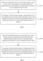
- a transformer area identification method including the following steps:
- step S4 specifically includes the following substeps:
- step S4 specifically includes the following substeps:
- step S4 further includes the following substep: step S43: if a same electric meter is determined to be in the suspected exclusive state and the suspected inclusive state successively, or is determined to be in the suspected inclusive state and the suspected exclusive state successively, resetting the electric meter to be in an initial state.
- the transformer area identification method includes the following step: step S6: merging adjacent identification domains, and repeating the above steps S1 to S5, till a whole power supply network of the transformer area is completely identified.
- the transformer area identification method collects power data based on a pure carrier network.
- transformer area identification method includes the following steps:
- step S9 specifically includes the following substeps:
- step S1 further includes the following substep: eliminating an empty user whose power is always zero from the identification domain directly.
- the present disclosure further provides a computer-readable storage medium storing a computer program for transformer area identification, where the computer program is run on a computer to perform the following steps:
- the present disclosure has the following beneficial effects.
- the transformer area identification method in the present disclosure determines a corresponding electric meter mounting relationship by identifying a power jump characteristic by using a power jump algorithm and based on a power statistic of each node in a power supply network of a transformer area.
- the identification based on a power jump can minimize the influence of line loss power and increase identification accuracy.
- the identification is performed based on change characteristics of unidentified total power and power of an electric meter in a to-be-identified domain, to reduce interference of a power fluctuation of an identified electric meter to the identification and increase the identification accuracy.
- iterative identification is used, so that the to-be-identified domain is smaller and a convergence speed is faster.
- the transformer area identification method in the present disclosure uses the power jump algorithm to identify the transformer area, thereby eliminating the influence of the line loss power and increasing the identification accuracy.
- the transformer area identification method combines iterative identification. As an identification process goes on, the convergence speed is faster, and the identification accuracy is higher.
- the transformer area identification method in the present disclosure uses high-precision time synchronization of a carrier network for the first time, and each carrier module regularly reads the power of its own node, to realize time synchronization of all read data.
- the carrier module reads the power regularly and adds a timestamp and an electric meter ID to generate power data.
- the power data is summarized by a concentrator to generate a power statistic for subsequent identification.
- the carrier module performs reading the window each time, thereby ensuring delay synchronization between various electric meters and further ensuring the accuracy of transformer area identification.
- a preferred embodiment of the present disclosure provides a transformer area identification method.
- the transformer area identification method uses a power jump algorithm to identify a transformer area, thereby eliminating the influence of line loss power and increasing identification accuracy.
- the transformer area identification method combines iterative identification. As an identification process goes on, a convergence speed is faster, and the identification accuracy is higher.
- the transformer area identification method includes the following steps:
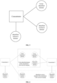
- a power supply network of the transformer area includes a plurality of power supply sub-networks of the transformer area.
- the power supply network of the transformer area includes several concentrators (namely, main electric meters) and several smart electric meters.
- One concentrator is connected to a plurality of smart electric meters by using power supply lines, and one concentrator and a plurality of smart electric meters connected to the concentrator constitute a power supply sub-network of the transformer area.
- the concentrators and the smart electric meters each are provided with a carrier module.
- the carrier module on a concentrator and the carrier module on each smart electric meter connected to the concentrator constitute a carrier sub-network, and each carrier sub-network is an identification domain.
- a plurality of carrier modules in the carrier sub-network are connected to each other by using a virtual power line carrier (PLC) line.
- PLC virtual power line carrier
- the PLC line does not exist physically, and it is only a logical line, and generated based on a power supply line by using a specific algorithm. However, in practical application, due to various types of interference, a line configuration error may occur, resulting in a transformer area identification error.
- a smart electric meter An in the power supply sub-network A of the transformer area should belong to the power supply sub-network A of the transformer area. Due to a line configuration error of the carrier network, the smart electric meter An is incorrectly added to the power supply sub-network B of the transformer area during transformer area identification based on the carrier network, resulting in the transformer area identification error.
- the power supply network of the transformer area is consistent with the carrier network of the transformer area.
- the transformer area identification method in the present disclosure is a process of deriving an accurate power supply network of the transformer area from an initial carrier network of the transformer area.
- the transformer area identification method in the present disclosure collects power data based on a pure carrier network.
- a broadband carrier system because all stations (STA) in the whole network are synchronized with network reference time of a gateway (CCO), that is, the carrier module (CCO) of a concentrator and carrier modules (STA) of all electric meters connected to the concentrator by using the carrier network keep synchronization based on the network reference time. Therefore, the power data based on the network reference time of the carrier system is well synchronized, ensuring synchronization and accuracy of power data collection. It can be understood that the carrier module reads real-time power regularly and adds an electric meter ID and an accurate timestamp of the identification domain to generate basic power data.
- the carrier module performs reading by window each time. For example, a window is three seconds and reading is performed once per second. In this way, three pieces of power data can be read in one round with an interval of 1 second. If the three pieces of data in the current round fluctuate smoothly, an average value can be used for feature matching. If there is a jump in the three pieces of data in the current round, processing is performed according to a pre-determined strategy. The strategy may be discarding the data in the current round or attempting to perform feature matching.
- the carrier module of the concentrator acts as a central coordinator of the carrier sub-network
- the carrier module of the smart electric meter acts as a station of the carrier sub-network.
- the concentrator is a unified electric power data collection device in a power supply sub-network of a transformer area. It can collect power and other electric power data of each electric meter in the network by using the carrier network, and can also measure total power and other electric power data of the whole power supply sub-network of the transformer area.
- step S1 power data of each electric meter in one identification domain (namely, power supply sub-network of the transformer area) and power data of the main electric meter (namely, concentrator) are collected by using the concentrator, and the identification domain is divided into the current-state identified domain and the current-state to-be-identified domain, where the current-state identified domain includes the current-state identified inclusive domain and the current-state identified exclusive domain.
- the current-state identified inclusive domain is composed of electric meters, confirmed to be included in the power supply sub-network of the transformer area, in the identification domain, the current-state identified exclusive domain is composed of electric meters confirmed to be excluded from the power supply sub-network of the transformer area, and the current-state to-be-identified domain is composed of electric meters not identified in the power supply sub-network of the transformer area. It can be also understood that an empty user whose power is always zero is eliminated from the identification domain directly and is not identified, to improve identification efficiency.
- the unidentified total power is equal to a difference between the total power of the power supply sub-network of the transformer area and the total power of the current-state identified inclusive domain, where the total power of the current-state identified inclusive domain is a sum of power of electric meters included in the current-state identified inclusive domain.
- the unidentified total power is not a sum of power of electric meters included in the current-state unidentified domain.
- step S3 the change of the unidentified total power and the change of the power of each electric meter in the current-state to-be-identified domain are calculated based on the power of each electric meter in the identification domain and the power of the main electric meter that are calculated in the step S1.
- step S4 specifically includes the following substeps:
- the effective power jump threshold should be significantly greater than a sum of smooth power fluctuation thresholds of all electric meters in the current-state unidentified domain, and the smooth power fluctuation threshold and the effective power jump threshold can be dynamically adjusted.
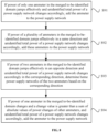
- step S41a due to a high reading frequency of the carrier module and a short reading interval, if the unidentified total power fluctuates smoothly, there is a large probability that power of each electric meter not identified in the power supply sub-network of the transformer area fluctuates smoothly. In this case, if power of only one electric meter in the current-state to-be-identified domain jumps effectively, there is a large probability that the electric meter does not belong to the power supply sub-network of the transformer area.
- This feature is defined as a suspected exclusion feature, and the electric meter is set to the suspected exclusive state.
- step S42a if a quantity of times that the suspected exclusion feature occurs on an electric meter is greater than a threshold such as 3 in a statistical process, it is confirmed that the electric meter does not belong to the power supply sub-network of the transformer area.
- This threshold is defined as an exclusion confirmation threshold, and the electric meter is removed from the current-state to-be-identified domain and added to the current-state identified exclusive domain.
- the quantity of the times that the suspected exclusion feature occurs is accumulated, and it is confirmed that the electric meter is exclusive when an accumulated quantity is greater the specified threshold, to improve a fault-tolerant capability of a calculation result.
- step S4 further includes the following substeps:
- the unidentified total power jumps effectively, and in this case, if power of only one electric meter in the current-state to-be-identified domain jumps effectively and approximately equivalently, there is a large probability that the electric meter belongs to the power supply sub-network of the transformer area.
- This feature is defined as a suspected inclusion feature, and the electric meter is set to the suspected inclusive state.
- step S42b if a quantity of times that the suspected inclusion feature occurs on an electric meter is greater than a threshold such as 3 in a statistical process, it is confirmed that the electric meter belongs to the power supply sub-network of the transformer area.
- This threshold is defined as an inclusion confirmation threshold, and the electric meter is removed from the current-state to-be-identified domain and added to the current-state identified inclusive domain.
- the quantity of the times that the suspected inclusion feature occurs is accumulated, and it is confirmed that the electric meter is inclusive when an accumulated quantity is greater the specified threshold, to improve the fault-tolerant capability of the calculation result.
- step S4 further includes the following substep: Step S43: If a same electric meter is determined to be in the suspected exclusive state and the suspected inclusive state successively, or is determined to be in the suspected inclusive state and the suspected exclusive state successively, reset the electric meter to be in an initial state, to prevent misjudgment and ensure accuracy of transformer area identification.
- step S5 power jump characteristics including the above suspected exclusion feature and suspected inclusion feature are identified to independently calculate respective identified inclusive domains and identified exclusive domains, and the stable-state identified inclusive domain, the stable-state identified exclusive domain, and the stable-state to-be-identified domain are formed through continuous iteration.
- the transformer area identification method further includes the following step: Step S6: Merge adjacent identification domains, and repeat the above steps S1 to S5, till a whole power supply network of the transformer area is completely identified.
- Step S6 Merge adjacent identification domains, and repeat the above steps S1 to S5, till a whole power supply network of the transformer area is completely identified.
- an identified inclusive domain, an identified exclusive domain, and a to-be-identified domain are formed for each concentrator, and the newly formed to-be-identified domain is identified.
- adjacent carrier sub-networks are merged repeatedly till the whole power supply network of the transformer area is derived.
- the transformer area identification method further includes the following steps:
- a result of merging carrier networks of two or more transformer areas is consistent with a result of merging power supply networks of the corresponding transformer areas, that is, all electric meters inside the plurality of merged transformer areas are in the identification domain, and none of electric meters outside the plurality of merged transformer areas are in the identification domain, it can be regarded that these carrier networks constitute a complete domain.
- a merged network is uniformly identified by using a main station.
- the merged identification domain includes the merged identified domain and the merged to-be-identified domain.
- steps S7, S8, and S9 may be performed independently or may be performed after the step S6.
- step S9 specifically includes the following substeps:
- the transformer area identification method in the present disclosure determines a corresponding electric meter mounting relationship by identifying a power jump characteristic by using a power jump algorithm and based on a power statistic of each node in a power supply network of a transformer area.
- the identification based on a power jump can minimize the influence of line loss power and increase identification accuracy.
- the identification is performed based on change characteristics of unidentified total power and power of an electric meter in a to-be-identified domain, to reduce interference of a power fluctuation of an identified electric meter to the identification and increase the identification accuracy.
- iterative identification is used, so that the to-be-identified domain is smaller and a convergence speed is faster.
- the transformer area identification method in the present disclosure uses the power jump algorithm to identify the transformer area, thereby eliminating the influence of the line loss power and increasing the identification accuracy.
- the transformer area identification method combines iterative identification. As an identification process goes on, the convergence speed is faster, and the identification accuracy is higher.
- the transformer area identification method in the present disclosure uses high-precision time synchronization of a carrier network for the first time, and each carrier module regularly reads power of its own node, to realize time synchronization of all read data.
- the carrier module reads the power regularly, and adds a timestamp and an electric meter ID to generate power data.
- the power data is summarized by a concentrator to generate a power statistic for subsequent identification.
- the carrier module performs reading by window each time, thereby ensuring delay synchronization between various electric meters and further ensuring accuracy of transformer area identification.
- Another embodiment of the present disclosure provides a computer-readable storage medium storing a computer program for transformer area identification, where the computer program is run on a computer to perform the following steps:
- step S4 preferably includes the following substeps:
- step S4 further includes the following substeps:
- step S4 further includes the following substep: Step S43: If a same electric meter is determined to be in the suspected exclusive state and the suspected inclusive state successively, or is determined to be in the suspected inclusive state and the suspected exclusive state successively, reset the electric meter to be in an initial state, to prevent misjudgment and ensure accuracy of transformer area identification.
- Step S6 Merge adjacent identification domains, and repeat the above steps S1 to S5, till a whole power supply network of the transformer area is completely identified.
- step S9 specifically includes the following substeps:
- a computer-readable medium may be in the following form: a floppy disk, a flexible disk, a hard disk, a magnetic tape, any other type of magnetic medium, a CD-ROM, any other type of optical medium, a punch card, a paper tape, any other type of physical medium with a hole pattern, a random access memory (RAM), a programmable read-only memory (PROM), an erasable programmable read-only memory (EPROM), a flash erasable programmable read-only memory (FLASH-EPROM), any other type of memory chip or cartridge, or any other type of medium that can be read by a computer.
- An instruction can be further transmitted or received by a transmission medium.
- the transmission medium may include any tangible or intangible medium.
- the transmission medium can be used to store, encode or carry an instruction to be executed by a machine, and includes a digital or analog communication signal or an intangible medium that facilitates communication with the above instruction.
- the transmission medium includes a coaxial cable, a copper wire, and an optical fiber, and includes a conductive wire of a bus used to transmit a computer data signal.
Landscapes
- Engineering & Computer Science (AREA)
- Power Engineering (AREA)
- Physics & Mathematics (AREA)
- General Physics & Mathematics (AREA)
- Remote Monitoring And Control Of Power-Distribution Networks (AREA)
- Management, Administration, Business Operations System, And Electronic Commerce (AREA)
Claims (10)
- Verfahren zur Identifizierung eines Transformatorbereichs, umfassend die folgenden Schritte:Schritt S1: Sammeln und Zählen von Leistung jedes Stromzählers in einer Identifizierungsdomäne und von Leistung eines Haupt-Stromzählers, worin die Identifizierungsdomäne eine identifizierte Domäne des aktuellen Zustands und eine zu identifizierende Domäne des aktuellen Zustands umfasst, und die identifizierte Domäne des aktuellen Zustands eine identifizierte inklusive Domäne des aktuellen Zustands und eine identifizierte exklusive Domäne des aktuellen Zustands umfasst;Schritt S2: Berechnen von nicht-identifizierter Gesamtleistung, worin die nicht-identifizierte Gesamtleistung eine Differenz zwischen der Leistung des Haupt-Stromzählers und der Gesamtleistung der identifizierten inklusiven Domäne des aktuellen Zustands ist;Schritt S3: Berechnen einer Änderung der nicht-identifizierten Gesamtleistung und einer Änderung der Leistung jedes Stromzählers in der zu identifizierenden Domäne des aktuellen Zustands;Schritt S4: Identifizieren eines Transformatorbereichs aufgrund der Änderung der nicht-identifizierten Gesamtleistung und der Änderung der Leistung jedes Stromzählers in der zu identifizierenden Domäne des aktuellen Zustands; undSchritt S5: Wiederholen von Schritten S1 bis S4, bis die Identifizierungsdomäne in eine identifizierte inklusive Domäne des stabilen Zustands, eine identifizierte exklusive Domäne des stabilen Zustands und eine zu identifizierende Domäne des stabilen Zustands unterteilt wird.
- Verfahren zur Identifizierung eines Transformatorbereichs nach Anspruch 1, worin Schritt S4 spezifisch die folgenden Teilschritte umfasst:Schritt S41a: wenn die nicht-identifizierte Gesamtleistung ruhig schwankt, wenn die Leistung von nur einem Stromzähler in der zu identifizierenden Domäne des aktuellen Zustands wirksam springt, Bestimmen, dass der Stromzähler sich in einem mutmaßlichen exklusiven Zustand befindet; undSchritt S42a: wenn eine Menge von Malen, dass es bestimmt wird, dass der Stromzähler sich in dem mutmaßlichen exklusiven Zustand befindet, eine Schwelle überschreitet, Entfernen des Stromzählers von der zu identifizierenden Domäne des aktuellen Zustands, und Hinzufügen des Stromzählers zur identifizierten exklusiven Domäne des aktuellen Zustands.
- Verfahren zur Identifizierung eines Transformatorbereichs nach Anspruch 2, worin Schritt S4 spezifisch die folgenden Teilschritte umfasst:Schritt S41b: wenn die nicht-identifizierte Gesamtleistung wirksam springt, wenn die Leistung von nur einem Stromzähler in der zu identifizierenden Domäne des aktuellen Zustands wirksam und wirkungsgleich springt, Bestimmen, dass der Stromzähler sich in einem mutmaßlichen inklusiven Zustand befindet; undSchritt S42b: wenn eine Menge von Malen, dass es bestimmt wird, dass der Stromzähler sich in dem mutmaßlichen inklusiven Zustand befindet, eine Schwelle überschreitet, Entfernen des Stromzählers von der zu identifizierenden Domäne des aktuellen Zustands, und Hinzufügen des Stromzählers zur identifizierten inklusiven Domäne des aktuellen Zustands.
- Verfahren zur Identifizierung eines Transformatorbereichs nach Anspruch 3, worin Schritt S4 ferner folgenden Teilschritt umfasst:
Schritt S43: wenn es bestimmt wird, dass derselbe Stromzähler sich in dem mutmaßlichen exklusiven Zustand und in dem mutmaßlichen inklusiven Zustand nacheinander befindet, oder es bestimmt wird, dass er sich in dem mutmaßlichen inklusiven Zustand und in dem mutmaßlichen exklusiven Zustand nacheinander befindet, Zurücksetzen des Stromzählers, damit er sich in einem Ausgangszustand befindet. - Verfahren zur Identifizierung eines Transformatorbereichs nach Anspruch 1, worin das Verfahren zur Identifizierung eines Transformatorbereichs ferner folgenden Schritt umfasst:
Schritt S6: Zusammenfügen von angrenzenden Identifizierungsdomänen, und Wiederholen der obigen Schritte S1 bis S5, bis ein ganzes Leistungsversorgungsnetz des Transformatorbereichs völlig identifiziert ist. - Verfahren zur Identifizierung eines Transformatorbereichs nach Anspruch 1, worin das Verfahren zur Identifizierung eines Transformatorbereichs Leistungsdaten aufgrund eines reinen Trägernetzes sammelt.
- Verfahren zur Identifizierung eines Transformatorbereichs nach Anspruch 1, worin das Verfahren zur Identifizierung eines Transformatorbereichs ferner die folgenden Schritte umfasst:Schritt S7: Zusammenfügen von Leistungsversorgungsnetzen einer Vielzahl von Transformatorbereichen, um eine komplette Domäne zu bilden, worin die komplette Domäne eine zusammengefügte identifizierte Domäne und eine zusammengefügte zu identifizierende Domäne umfasst, die zusammengefügte identifizierte Domäne aus bestätigten Stromzählern in den Leistungsversorgungsnetzen der Transformatorbereiche besteht, und die zusammengefügte zu identifizierende Domäne aus nicht-identifizierten Stromzählern besteht;Schritt S8: Berechnen der nicht-identifizierten Gesamtleistung jedes Leistungsversorgungsnetzes und der Leistung jedes Stromzählers in der zusammengefügten zu identifizierenden Domäne; undSchritt S9: Identifizieren des Transformatorbereichs aufgrund einer Änderung der Leistung jedes Stromzählers in der zusammengefügten zu identifizierenden Domäne und einer Änderung der nicht-identifizierten Gesamtleistung jedes Leistungsversorgungsnetzes.
- Verfahren zur Identifizierung eines Transformatorbereichs nach Anspruch 7, worin Schritt S9 spezifisch die folgenden Teilschritte umfasst:Schritt S91: wenn die Leistung von nur einem Stromzähler in der zusammengefügten zu identifizierenden Domäne wirksam springt und die nicht-identifizierte Gesamtleistung eines Leistungsversorgungsnetzes sich dementsprechend ändert, Hinzufügen des Stromzählers zum Leistungsversorgungsnetz;Schritt S92: wenn die Leistung einer Vielzahl von Stromzählern in der zusammengefügten zu identifizierenden Domäne wirksam in einer gleichen Richtung springt und die nicht-identifizierte Gesamtleistung eines Leistungsversorgungsnetzes sich dementsprechend ändert, Hinzufügen dieser Stromzähler zum Leistungsversorgungsnetz;Schritt S93: wenn die Leistung von zwei Stromzählern in der zusammengefügten zu identifizierenden Domäne wirksam in einer entgegengesetzten Richtung springt und die nicht-identifizierte Gesamtleistung eines Leistungsversorgungsnetzes sich dementsprechend in einer entsprechenden Richtung ändert, Hinzufügen der zwei Stromzähler zu entsprechenden Leistungsversorgungsnetzen aufgrund der entsprechenden Richtung; undSchritt S94: wenn die Leistung eines Stromzählers in der zusammengefügten zu identifizierenden Domäne sich ändert und ein Änderungswert größer ist als eine Summe von absoluten Werten von Leistungsänderungen anderer Stromzähler und die nicht-identifizierte Gesamtleistung eines Leistungsversorgungsnetzes sich dementsprechend ändert, Hinzufügen des Stromzählers zum Leistungsversorgungsnetz.
- Verfahren zur Identifizierung eines Transformatorbereichs nach Anspruch 1, worin Schritt S 1 ferner folgenden Teilschritt umfasst:
Beseitigen eines leeren Benutzers, dessen Leistung immer gleich null ist, von der Identifizierungsdomäne direkt. - Computerlesbares Speichermedium, in dem ein Computerprogramm zur Identifizierung eines Transformatorbereichs gespeichert ist, worin das Computerprogramm, wenn es auf einem Computer ausgeführt wird, bewirkt, dass der Computer die folgenden Schritte durchführt:Schritt S1: Sammeln und Zählen von Leistung jedes Stromzählers in einer Identifizierungsdomäne und von Leistung eines Haupt-Stromzählers, worin die Identifizierungsdomäne eine identifizierte Domäne des aktuellen Zustands und eine zu identifizierende Domäne des aktuellen Zustands umfasst, und die identifizierte Domäne des aktuellen Zustands eine identifizierte inklusive Domäne des aktuellen Zustands und eine identifizierte exklusive Domäne des aktuellen Zustands umfasst;Schritt S2: Berechnen von nicht-identifizierter Gesamtleistung, worin die nicht-identifizierte Gesamtleistung eine Differenz zwischen der Leistung des Haupt-Stromzählers und der Gesamtleistung der identifizierten inklusiven Domäne des aktuellen Zustands ist;Schritt S3: Berechnen einer Änderung der nicht-identifizierten Gesamtleistung und einer Änderung der Leistung jedes Stromzählers in der zu identifizierenden Domäne des aktuellen Zustands;Schritt S4: Identifizieren eines Transformatorbereichs aufgrund der Änderung der nicht-identifizierten Gesamtleistung und der Änderung der Leistung jedes Stromzählers in der zu identifizierenden Domäne des aktuellen Zustands; undSchritt S5: Wiederholen von Schritten S1 bis S4, bis die Identifizierungsdomäne in eine identifizierte inklusive Domäne des stabilen Zustands, eine identifizierte exklusive Domäne des stabilen Zustands und eine zu identifizierende Domäne des stabilen Zustands unterteilt wird.
Applications Claiming Priority (2)
| Application Number | Priority Date | Filing Date | Title |
|---|---|---|---|
| CN201910357968.2A CN110212518B (zh) | 2019-04-30 | 2019-04-30 | 台区识别方法、计算机可读取的存储介质 |
| PCT/CN2020/085512 WO2020221035A1 (zh) | 2019-04-30 | 2020-04-20 | 台区识别方法、计算机可读取的存储介质 |
Publications (4)
| Publication Number | Publication Date |
|---|---|
| EP3965246A1 EP3965246A1 (de) | 2022-03-09 |
| EP3965246A4 EP3965246A4 (de) | 2023-01-18 |
| EP3965246B1 true EP3965246B1 (de) | 2024-04-17 |
| EP3965246C0 EP3965246C0 (de) | 2024-04-17 |
Family
ID=67786621
Family Applications (1)
| Application Number | Title | Priority Date | Filing Date |
|---|---|---|---|
| EP20798782.7A Active EP3965246B1 (de) | 2019-04-30 | 2020-04-20 | Verfahren zur identifizierung eines transformatorbereichs und computerlesbares speichermedium |
Country Status (6)
| Country | Link |
|---|---|
| US (1) | US11982695B2 (de) |
| EP (1) | EP3965246B1 (de) |
| JP (1) | JP7588088B2 (de) |
| CN (1) | CN110212518B (de) |
| MA (1) | MA55819A (de) |
| WO (1) | WO2020221035A1 (de) |
Families Citing this family (17)
| Publication number | Priority date | Publication date | Assignee | Title |
|---|---|---|---|---|
| CN110212518B (zh) * | 2019-04-30 | 2020-03-24 | 北京市腾河智慧能源科技有限公司 | 台区识别方法、计算机可读取的存储介质 |
| CN112581306B (zh) * | 2019-09-30 | 2023-07-28 | 广东电网有限责任公司佛山供电局 | 一种基于穷举的区域网络拓扑关系确认方法、装置和系统 |
| CN110932917A (zh) * | 2019-12-24 | 2020-03-27 | 深圳市国电科技通信有限公司 | 一种基于高频同步采集和边缘计算的台区拓扑发现方法 |
| CN111208351B (zh) * | 2020-01-17 | 2022-05-17 | 北京市腾河电子技术有限公司 | 基于负荷跳变计算供电线路阻抗的方法、存储介质 |
| CN111289942B (zh) * | 2020-01-21 | 2021-01-05 | 北京市腾河电子技术有限公司 | 基于单一负荷跳变进行测量域误差分析的方法及系统、存储介质 |
| CN111650431B (zh) * | 2020-05-26 | 2022-06-14 | 珠海中慧微电子有限公司 | 一种电表台区识别方法 |
| CN112672418B (zh) * | 2020-12-03 | 2024-03-12 | 江苏林洋能源股份有限公司 | 一种电表和主站之间通过载波集中器自注册的方法 |
| CN113517687B (zh) * | 2021-05-28 | 2023-07-21 | 国网浙江省电力有限公司营销服务中心 | 一种基于特征信号的低压台区拓扑识别方法及装置 |
| CN113746589B (zh) * | 2021-09-01 | 2024-01-30 | 钜泉光电科技(上海)股份有限公司 | 基于过零ntb的台区识别方法 |
| CN114125586B (zh) * | 2021-11-22 | 2024-03-19 | 国网辽宁省电力有限公司鞍山供电公司 | 一种基于混合数据驱动的hplc设备id校对方法 |
| CN114123190B (zh) * | 2021-11-30 | 2024-11-08 | 广东电网有限责任公司 | 确定电表所属目标台区的方法、装置、电子设备及存储介质 |
| CN114912526B (zh) * | 2022-05-13 | 2024-04-26 | 北京市腾河电子技术有限公司 | 台区识别方法及系统、电子设备、存储介质 |
| CN115453444A (zh) * | 2022-08-29 | 2022-12-09 | 中能瑞通(北京)科技有限公司 | 一种台区电表拓扑识别及失准判断的方法 |
| CN115811334A (zh) * | 2022-11-25 | 2023-03-17 | 北京智芯微电子科技有限公司 | 目标台区识别方法、装置、计算机设备及存储介质 |
| CN117290736A (zh) * | 2023-09-27 | 2023-12-26 | 深圳供电局有限公司 | 一种基于电流事件概率的户变关系识别方法及系统 |
| CN119848570B (zh) * | 2024-12-25 | 2025-11-14 | 重庆大学 | 一种基于混合算法框架的低压配电台区用户相序识别方法 |
| CN119482448A (zh) * | 2025-01-13 | 2025-02-18 | 济南安迅科技有限公司 | 基于需求预测的海上风电组电力资源调度方法及系统 |
Family Cites Families (14)
| Publication number | Priority date | Publication date | Assignee | Title |
|---|---|---|---|---|
| US9647454B2 (en) | 2011-08-31 | 2017-05-09 | Aclara Technologies Llc | Methods and apparatus for determining conditions of power lines |
| CN104105973B (zh) | 2012-02-09 | 2016-06-29 | 三菱电机株式会社 | 电能计量装置、电能计量装置的被盗检测方法、以及电力供应系统 |
| US10571493B2 (en) | 2014-02-25 | 2020-02-25 | Itron, Inc. | Smart grid topology estimator |
| CN104092481B (zh) * | 2014-07-17 | 2016-04-20 | 江苏林洋能源股份有限公司 | 一种通过电压特征区分台区和相别的方法 |
| US20160109491A1 (en) * | 2014-10-20 | 2016-04-21 | Itron, Inc. | Grid topology mapping with voltage data |
| US10418811B2 (en) * | 2017-09-12 | 2019-09-17 | Sas Institute Inc. | Electric power grid supply and load prediction using cleansed time series data |
| CN108683437B (zh) * | 2018-05-17 | 2021-06-22 | 杭州海兴电力科技股份有限公司 | 基于宽带载波的台区识别方法 |
| CN108535543B (zh) * | 2018-05-22 | 2021-05-11 | 宁波三星医疗电气股份有限公司 | 基于集中器与电表同步采样的台区相位识别方法 |
| CN108805457B (zh) | 2018-06-19 | 2021-05-14 | 宁波迦南智能电气股份有限公司 | 一种电能表台区识别方法 |
| CN109066990B (zh) * | 2018-09-07 | 2020-10-27 | 光一科技股份有限公司 | 基于集中调度的台区电网末端扰动拓扑结构识别方法 |
| CN109444800B (zh) * | 2018-09-28 | 2021-11-19 | 国网湖南省电力有限公司 | 基于无线通信采集的台区识别方法 |
| CN109256866B (zh) * | 2018-11-19 | 2022-02-11 | 国网四川省电力公司成都供电公司 | 提升台区拓扑识别效率及线损精度的检测终端 |
| CN109217478B (zh) * | 2018-11-19 | 2021-03-12 | 深圳市均方根科技有限公司 | 低压台区拓扑关系识别方法、集中器以及存储介质 |
| CN110212518B (zh) | 2019-04-30 | 2020-03-24 | 北京市腾河智慧能源科技有限公司 | 台区识别方法、计算机可读取的存储介质 |
-
2019
- 2019-04-30 CN CN201910357968.2A patent/CN110212518B/zh active Active
-
2020
- 2020-04-20 JP JP2021562065A patent/JP7588088B2/ja active Active
- 2020-04-20 WO PCT/CN2020/085512 patent/WO2020221035A1/zh not_active Ceased
- 2020-04-20 MA MA055819A patent/MA55819A/fr unknown
- 2020-04-20 US US17/594,528 patent/US11982695B2/en active Active
- 2020-04-20 EP EP20798782.7A patent/EP3965246B1/de active Active
Also Published As
| Publication number | Publication date |
|---|---|
| US20220196714A1 (en) | 2022-06-23 |
| EP3965246A4 (de) | 2023-01-18 |
| EP3965246A1 (de) | 2022-03-09 |
| CN110212518A (zh) | 2019-09-06 |
| JP7588088B2 (ja) | 2024-11-21 |
| JP2022531101A (ja) | 2022-07-06 |
| US11982695B2 (en) | 2024-05-14 |
| CN110212518B (zh) | 2020-03-24 |
| WO2020221035A1 (zh) | 2020-11-05 |
| EP3965246C0 (de) | 2024-04-17 |
| MA55819A (fr) | 2022-03-09 |
Similar Documents
| Publication | Publication Date | Title |
|---|---|---|
| EP3965246B1 (de) | Verfahren zur identifizierung eines transformatorbereichs und computerlesbares speichermedium | |
| US11947624B2 (en) | Method and system for analyzing error of measurement domain based on single load jump, and storage medium | |
| CN112966219B (zh) | 识别户表与表箱关系的方法及系统、设备、介质 | |
| CN111446988A (zh) | 基于hplc载波通信的低压台区变线户拓扑识别边缘计算方法 | |
| CN109633326A (zh) | 一种可拆卸式线损分析系统 | |
| CN113724101B (zh) | 台区的箱表关系识别方法及系统、设备、存储介质 | |
| CN113985339B (zh) | 智能电表的误差诊断方法及系统、设备、存储介质 | |
| CN111404270A (zh) | 基于同步计数法的低压配电台区拓扑层次识别方法、装置及设备 | |
| CN113092935A (zh) | 一种识别小负荷线路拓扑的方法及系统、设备、存储介质 | |
| Soumalas et al. | A data driven approach to distribution network topology identification | |
| CN113721094B (zh) | 低压台区用采系统的误差分析方法及系统、设备、存储介质 | |
| CN111835006A (zh) | 一种基于电压曲线和最小二乘的低压台区拓扑识别方法 | |
| CN111711469B (zh) | 基于信噪比的台区识别方法、系统、存储介质及sta节点 | |
| CN115494382B (zh) | 判断智能开关上下级关系的方法及系统、设备、存储介质 | |
| CN119483797A (zh) | 配电网设备同步时间修正方法及系统、电子设备、存储介质 | |
| CN115207909B (zh) | 一种台区拓扑识别方法、装置、设备及存储介质 | |
| CN117368831A (zh) | 低压台区同步时钟误差的测量方法及系统、设备、介质 | |
| CN115225244B (zh) | 低压集抄电能表时钟对时方法、装置、主设备及介质 | |
| CN111478311A (zh) | 一种电网任意分区线损计算方法及系统 | |
| CN117407655A (zh) | 一种低压线相户关系识别方法、装置、设备和存储介质 | |
| CN117411190B (zh) | 基于多源信息的配电网拓扑识别方法、设备、系统及介质 | |
| CN111260195A (zh) | 一种低压用户串户检测方法及存储介质 | |
| CN111598374A (zh) | 低压交流市电台区智能识别方法 | |
| Chen et al. | Identification of Relationships between Electric Meter Boxes and Smart Meters in Power Communication | |
| CN109375055A (zh) | 一种相量测量系统的检测方法、系统、装置及储存介质 |
Legal Events
| Date | Code | Title | Description |
|---|---|---|---|
| STAA | Information on the status of an ep patent application or granted ep patent |
Free format text: STATUS: THE INTERNATIONAL PUBLICATION HAS BEEN MADE |
|
| PUAI | Public reference made under article 153(3) epc to a published international application that has entered the european phase |
Free format text: ORIGINAL CODE: 0009012 |
|
| STAA | Information on the status of an ep patent application or granted ep patent |
Free format text: STATUS: REQUEST FOR EXAMINATION WAS MADE |
|
| 17P | Request for examination filed |
Effective date: 20211126 |
|
| AK | Designated contracting states |
Kind code of ref document: A1 Designated state(s): AL AT BE BG CH CY CZ DE DK EE ES FI FR GB GR HR HU IE IS IT LI LT LU LV MC MK MT NL NO PL PT RO RS SE SI SK SM TR |
|
| DAX | Request for extension of the european patent (deleted) | ||
| A4 | Supplementary search report drawn up and despatched |
Effective date: 20221220 |
|
| RIC1 | Information provided on ipc code assigned before grant |
Ipc: G01R 22/10 20060101ALI20221214BHEP Ipc: G01R 21/133 20060101ALI20221214BHEP Ipc: G01R 22/06 20060101ALI20221214BHEP Ipc: G01R 19/25 20060101ALI20221214BHEP Ipc: H02J 3/00 20060101AFI20221214BHEP |
|
| GRAP | Despatch of communication of intention to grant a patent |
Free format text: ORIGINAL CODE: EPIDOSNIGR1 |
|
| STAA | Information on the status of an ep patent application or granted ep patent |
Free format text: STATUS: GRANT OF PATENT IS INTENDED |
|
| RIC1 | Information provided on ipc code assigned before grant |
Ipc: G01R 22/10 20060101ALI20231026BHEP Ipc: G01R 21/133 20060101ALI20231026BHEP Ipc: G01R 22/06 20060101ALI20231026BHEP Ipc: G01R 19/25 20060101ALI20231026BHEP Ipc: H02J 3/00 20060101AFI20231026BHEP |
|
| INTG | Intention to grant announced |
Effective date: 20231113 |
|
| GRAS | Grant fee paid |
Free format text: ORIGINAL CODE: EPIDOSNIGR3 |
|
| GRAA | (expected) grant |
Free format text: ORIGINAL CODE: 0009210 |
|
| STAA | Information on the status of an ep patent application or granted ep patent |
Free format text: STATUS: THE PATENT HAS BEEN GRANTED |
|
| AK | Designated contracting states |
Kind code of ref document: B1 Designated state(s): AL AT BE BG CH CY CZ DE DK EE ES FI FR GB GR HR HU IE IS IT LI LT LU LV MC MK MT NL NO PL PT RO RS SE SI SK SM TR |
|
| REG | Reference to a national code |
Ref country code: GB Ref legal event code: FG4D |
|
| REG | Reference to a national code |
Ref country code: CH Ref legal event code: EP |
|
| REG | Reference to a national code |
Ref country code: IE Ref legal event code: FG4D Ref country code: DE Ref legal event code: R096 Ref document number: 602020029255 Country of ref document: DE |
|
| U01 | Request for unitary effect filed |
Effective date: 20240516 |
|
| U07 | Unitary effect registered |
Designated state(s): AT BE BG DE DK EE FI FR IT LT LU LV MT NL PT SE SI Effective date: 20240527 |
|
| U20 | Renewal fee for the european patent with unitary effect paid |
Year of fee payment: 5 Effective date: 20240524 |
|
| PG25 | Lapsed in a contracting state [announced via postgrant information from national office to epo] |
Ref country code: IS Free format text: LAPSE BECAUSE OF FAILURE TO SUBMIT A TRANSLATION OF THE DESCRIPTION OR TO PAY THE FEE WITHIN THE PRESCRIBED TIME-LIMIT Effective date: 20240817 |
|
| PG25 | Lapsed in a contracting state [announced via postgrant information from national office to epo] |
Ref country code: HR Free format text: LAPSE BECAUSE OF FAILURE TO SUBMIT A TRANSLATION OF THE DESCRIPTION OR TO PAY THE FEE WITHIN THE PRESCRIBED TIME-LIMIT Effective date: 20240417 |
|
| PG25 | Lapsed in a contracting state [announced via postgrant information from national office to epo] |
Ref country code: GR Free format text: LAPSE BECAUSE OF FAILURE TO SUBMIT A TRANSLATION OF THE DESCRIPTION OR TO PAY THE FEE WITHIN THE PRESCRIBED TIME-LIMIT Effective date: 20240718 |
|
| PG25 | Lapsed in a contracting state [announced via postgrant information from national office to epo] |
Ref country code: ES Free format text: LAPSE BECAUSE OF FAILURE TO SUBMIT A TRANSLATION OF THE DESCRIPTION OR TO PAY THE FEE WITHIN THE PRESCRIBED TIME-LIMIT Effective date: 20240417 |
|
| PG25 | Lapsed in a contracting state [announced via postgrant information from national office to epo] |
Ref country code: PL Free format text: LAPSE BECAUSE OF FAILURE TO SUBMIT A TRANSLATION OF THE DESCRIPTION OR TO PAY THE FEE WITHIN THE PRESCRIBED TIME-LIMIT Effective date: 20240417 |
|
| PG25 | Lapsed in a contracting state [announced via postgrant information from national office to epo] |
Ref country code: PL Free format text: LAPSE BECAUSE OF FAILURE TO SUBMIT A TRANSLATION OF THE DESCRIPTION OR TO PAY THE FEE WITHIN THE PRESCRIBED TIME-LIMIT Effective date: 20240417 Ref country code: NO Free format text: LAPSE BECAUSE OF FAILURE TO SUBMIT A TRANSLATION OF THE DESCRIPTION OR TO PAY THE FEE WITHIN THE PRESCRIBED TIME-LIMIT Effective date: 20240717 Ref country code: IS Free format text: LAPSE BECAUSE OF FAILURE TO SUBMIT A TRANSLATION OF THE DESCRIPTION OR TO PAY THE FEE WITHIN THE PRESCRIBED TIME-LIMIT Effective date: 20240817 Ref country code: HR Free format text: LAPSE BECAUSE OF FAILURE TO SUBMIT A TRANSLATION OF THE DESCRIPTION OR TO PAY THE FEE WITHIN THE PRESCRIBED TIME-LIMIT Effective date: 20240417 Ref country code: GR Free format text: LAPSE BECAUSE OF FAILURE TO SUBMIT A TRANSLATION OF THE DESCRIPTION OR TO PAY THE FEE WITHIN THE PRESCRIBED TIME-LIMIT Effective date: 20240718 Ref country code: ES Free format text: LAPSE BECAUSE OF FAILURE TO SUBMIT A TRANSLATION OF THE DESCRIPTION OR TO PAY THE FEE WITHIN THE PRESCRIBED TIME-LIMIT Effective date: 20240417 Ref country code: RS Free format text: LAPSE BECAUSE OF FAILURE TO SUBMIT A TRANSLATION OF THE DESCRIPTION OR TO PAY THE FEE WITHIN THE PRESCRIBED TIME-LIMIT Effective date: 20240717 |
|
| REG | Reference to a national code |
Ref country code: CH Ref legal event code: PL |
|
| REG | Reference to a national code |
Ref country code: DE Ref legal event code: R097 Ref document number: 602020029255 Country of ref document: DE |
|
| PG25 | Lapsed in a contracting state [announced via postgrant information from national office to epo] |
Ref country code: CZ Free format text: LAPSE BECAUSE OF FAILURE TO SUBMIT A TRANSLATION OF THE DESCRIPTION OR TO PAY THE FEE WITHIN THE PRESCRIBED TIME-LIMIT Effective date: 20240417 |
|
| PG25 | Lapsed in a contracting state [announced via postgrant information from national office to epo] |
Ref country code: SK Free format text: LAPSE BECAUSE OF FAILURE TO SUBMIT A TRANSLATION OF THE DESCRIPTION OR TO PAY THE FEE WITHIN THE PRESCRIBED TIME-LIMIT Effective date: 20240417 Ref country code: RO Free format text: LAPSE BECAUSE OF FAILURE TO SUBMIT A TRANSLATION OF THE DESCRIPTION OR TO PAY THE FEE WITHIN THE PRESCRIBED TIME-LIMIT Effective date: 20240417 |
|
| PG25 | Lapsed in a contracting state [announced via postgrant information from national office to epo] |
Ref country code: SM Free format text: LAPSE BECAUSE OF FAILURE TO SUBMIT A TRANSLATION OF THE DESCRIPTION OR TO PAY THE FEE WITHIN THE PRESCRIBED TIME-LIMIT Effective date: 20240417 |
|
| PG25 | Lapsed in a contracting state [announced via postgrant information from national office to epo] |
Ref country code: SM Free format text: LAPSE BECAUSE OF FAILURE TO SUBMIT A TRANSLATION OF THE DESCRIPTION OR TO PAY THE FEE WITHIN THE PRESCRIBED TIME-LIMIT Effective date: 20240417 Ref country code: SK Free format text: LAPSE BECAUSE OF FAILURE TO SUBMIT A TRANSLATION OF THE DESCRIPTION OR TO PAY THE FEE WITHIN THE PRESCRIBED TIME-LIMIT Effective date: 20240417 Ref country code: RO Free format text: LAPSE BECAUSE OF FAILURE TO SUBMIT A TRANSLATION OF THE DESCRIPTION OR TO PAY THE FEE WITHIN THE PRESCRIBED TIME-LIMIT Effective date: 20240417 Ref country code: CZ Free format text: LAPSE BECAUSE OF FAILURE TO SUBMIT A TRANSLATION OF THE DESCRIPTION OR TO PAY THE FEE WITHIN THE PRESCRIBED TIME-LIMIT Effective date: 20240417 Ref country code: CH Free format text: LAPSE BECAUSE OF NON-PAYMENT OF DUE FEES Effective date: 20240430 Ref country code: MC Free format text: LAPSE BECAUSE OF FAILURE TO SUBMIT A TRANSLATION OF THE DESCRIPTION OR TO PAY THE FEE WITHIN THE PRESCRIBED TIME-LIMIT Effective date: 20240417 |
|
| PLBE | No opposition filed within time limit |
Free format text: ORIGINAL CODE: 0009261 |
|
| STAA | Information on the status of an ep patent application or granted ep patent |
Free format text: STATUS: NO OPPOSITION FILED WITHIN TIME LIMIT |
|
| 26N | No opposition filed |
Effective date: 20250120 |
|
| GBPC | Gb: european patent ceased through non-payment of renewal fee |
Effective date: 20240717 |
|
| PG25 | Lapsed in a contracting state [announced via postgrant information from national office to epo] |
Ref country code: IE Free format text: LAPSE BECAUSE OF NON-PAYMENT OF DUE FEES Effective date: 20240420 |
|
| PG25 | Lapsed in a contracting state [announced via postgrant information from national office to epo] |
Ref country code: GB Free format text: LAPSE BECAUSE OF NON-PAYMENT OF DUE FEES Effective date: 20240717 |
|
| U20 | Renewal fee for the european patent with unitary effect paid |
Year of fee payment: 6 Effective date: 20250424 |
|
| VS25 | Lapsed in a validation state [announced via postgrant information from nat. office to epo] |
Ref country code: MD Free format text: LAPSE BECAUSE OF FAILURE TO SUBMIT A TRANSLATION OF THE DESCRIPTION OR TO PAY THE FEE WITHIN THE PRESCRIBED TIME-LIMIT Effective date: 20240417 |
|
| PG25 | Lapsed in a contracting state [announced via postgrant information from national office to epo] |
Ref country code: CY Free format text: LAPSE BECAUSE OF FAILURE TO SUBMIT A TRANSLATION OF THE DESCRIPTION OR TO PAY THE FEE WITHIN THE PRESCRIBED TIME-LIMIT; INVALID AB INITIO Effective date: 20200420 |
|
| PG25 | Lapsed in a contracting state [announced via postgrant information from national office to epo] |
Ref country code: HU Free format text: LAPSE BECAUSE OF FAILURE TO SUBMIT A TRANSLATION OF THE DESCRIPTION OR TO PAY THE FEE WITHIN THE PRESCRIBED TIME-LIMIT; INVALID AB INITIO Effective date: 20200420 |
|
| VS25 | Lapsed in a validation state [announced via postgrant information from nat. office to epo] |
Ref country code: MA Free format text: FAILURE TO ELECT DOMICILE IN THE NATIONAL COUNTRY Effective date: 20240718 |