EP3965228B1 - Method for synthesizing vortex electromagnetic field having high orbital angular momentum mode number - Google Patents
Method for synthesizing vortex electromagnetic field having high orbital angular momentum mode number Download PDFInfo
- Publication number
- EP3965228B1 EP3965228B1 EP20923684.3A EP20923684A EP3965228B1 EP 3965228 B1 EP3965228 B1 EP 3965228B1 EP 20923684 A EP20923684 A EP 20923684A EP 3965228 B1 EP3965228 B1 EP 3965228B1
- Authority
- EP
- European Patent Office
- Prior art keywords
- vortex
- antenna
- wave
- waves
- elements
- Prior art date
- Legal status (The legal status is an assumption and is not a legal conclusion. Google has not performed a legal analysis and makes no representation as to the accuracy of the status listed.)
- Active
Links
Images

Classifications
-
- H—ELECTRICITY
- H01—ELECTRIC ELEMENTS
- H01Q—ANTENNAS, i.e. RADIO AERIALS
- H01Q15/00—Devices for reflection, refraction, diffraction or polarisation of waves radiated from an antenna, e.g. quasi-optical devices
- H01Q15/0006—Devices acting selectively as reflecting surface, as diffracting or as refracting device, e.g. frequency filtering or angular spatial filtering devices
- H01Q15/0086—Devices acting selectively as reflecting surface, as diffracting or as refracting device, e.g. frequency filtering or angular spatial filtering devices said selective devices having materials with a synthesized negative refractive index, e.g. metamaterials or left-handed materials
-
- H—ELECTRICITY
- H01—ELECTRIC ELEMENTS
- H01Q—ANTENNAS, i.e. RADIO AERIALS
- H01Q3/00—Arrangements for changing or varying the orientation or the shape of the directional pattern of the waves radiated from an antenna or antenna system
- H01Q3/26—Arrangements for changing or varying the orientation or the shape of the directional pattern of the waves radiated from an antenna or antenna system varying the relative phase or relative amplitude of energisation between two or more active radiating elements; varying the distribution of energy across a radiating aperture
- H01Q3/30—Arrangements for changing or varying the orientation or the shape of the directional pattern of the waves radiated from an antenna or antenna system varying the relative phase or relative amplitude of energisation between two or more active radiating elements; varying the distribution of energy across a radiating aperture varying the relative phase between the radiating elements of an array
- H01Q3/34—Arrangements for changing or varying the orientation or the shape of the directional pattern of the waves radiated from an antenna or antenna system varying the relative phase or relative amplitude of energisation between two or more active radiating elements; varying the distribution of energy across a radiating aperture varying the relative phase between the radiating elements of an array by electrical means
- H01Q3/40—Arrangements for changing or varying the orientation or the shape of the directional pattern of the waves radiated from an antenna or antenna system varying the relative phase or relative amplitude of energisation between two or more active radiating elements; varying the distribution of energy across a radiating aperture varying the relative phase between the radiating elements of an array by electrical means with phasing matrix
-
- H—ELECTRICITY
- H01—ELECTRIC ELEMENTS
- H01Q—ANTENNAS, i.e. RADIO AERIALS
- H01Q3/00—Arrangements for changing or varying the orientation or the shape of the directional pattern of the waves radiated from an antenna or antenna system
- H01Q3/26—Arrangements for changing or varying the orientation or the shape of the directional pattern of the waves radiated from an antenna or antenna system varying the relative phase or relative amplitude of energisation between two or more active radiating elements; varying the distribution of energy across a radiating aperture
- H01Q3/30—Arrangements for changing or varying the orientation or the shape of the directional pattern of the waves radiated from an antenna or antenna system varying the relative phase or relative amplitude of energisation between two or more active radiating elements; varying the distribution of energy across a radiating aperture varying the relative phase between the radiating elements of an array
- H01Q3/32—Arrangements for changing or varying the orientation or the shape of the directional pattern of the waves radiated from an antenna or antenna system varying the relative phase or relative amplitude of energisation between two or more active radiating elements; varying the distribution of energy across a radiating aperture varying the relative phase between the radiating elements of an array by mechanical means
-
- H—ELECTRICITY
- H01—ELECTRIC ELEMENTS
- H01Q—ANTENNAS, i.e. RADIO AERIALS
- H01Q1/00—Details of, or arrangements associated with, antennas
- H01Q1/12—Supports; Mounting means
- H01Q1/22—Supports; Mounting means by structural association with other equipment or articles
- H01Q1/24—Supports; Mounting means by structural association with other equipment or articles with receiving set
-
- H—ELECTRICITY
- H01—ELECTRIC ELEMENTS
- H01Q—ANTENNAS, i.e. RADIO AERIALS
- H01Q21/00—Antenna arrays or systems
-
- H—ELECTRICITY
- H01—ELECTRIC ELEMENTS
- H01Q—ANTENNAS, i.e. RADIO AERIALS
- H01Q21/00—Antenna arrays or systems
- H01Q21/0006—Particular feeding systems
-
- H—ELECTRICITY
- H01—ELECTRIC ELEMENTS
- H01Q—ANTENNAS, i.e. RADIO AERIALS
- H01Q21/00—Antenna arrays or systems
- H01Q21/06—Arrays of individually energised antenna units similarly polarised and spaced apart
- H01Q21/20—Arrays of individually energised antenna units similarly polarised and spaced apart the units being spaced along or adjacent to a curvilinear path
-
- H—ELECTRICITY
- H01—ELECTRIC ELEMENTS
- H01Q—ANTENNAS, i.e. RADIO AERIALS
- H01Q3/00—Arrangements for changing or varying the orientation or the shape of the directional pattern of the waves radiated from an antenna or antenna system
- H01Q3/26—Arrangements for changing or varying the orientation or the shape of the directional pattern of the waves radiated from an antenna or antenna system varying the relative phase or relative amplitude of energisation between two or more active radiating elements; varying the distribution of energy across a radiating aperture
- H01Q3/267—Phased-array testing or checking devices
-
- H—ELECTRICITY
- H01—ELECTRIC ELEMENTS
- H01Q—ANTENNAS, i.e. RADIO AERIALS
- H01Q3/00—Arrangements for changing or varying the orientation or the shape of the directional pattern of the waves radiated from an antenna or antenna system
- H01Q3/26—Arrangements for changing or varying the orientation or the shape of the directional pattern of the waves radiated from an antenna or antenna system varying the relative phase or relative amplitude of energisation between two or more active radiating elements; varying the distribution of energy across a radiating aperture
- H01Q3/30—Arrangements for changing or varying the orientation or the shape of the directional pattern of the waves radiated from an antenna or antenna system varying the relative phase or relative amplitude of energisation between two or more active radiating elements; varying the distribution of energy across a radiating aperture varying the relative phase between the radiating elements of an array
Definitions
- the present invention belongs to the new technical field of microwave (electromagnetic wave) imaging, and particularly relates to a method for synthesizing vortex electromagnetic (EM) wave carrying high orbital angular momentum (OAM) mode.
- EM vortex electromagnetic
- OAM orbital angular momentum
- Orbital Angular Momentum is an important physical value of the vortex electromagnetic (EM) field, and studies have indicated that vortex EM waves carrying different OAM modes are orthogonal each other, and more information can be modulated on it. Therefore, the researchers have extensively investigated the applications of vortex EM wave carrying OAM in many fields, such as communication and imaging.
- the radiated fields of vortex EM wave carrying different OAM modes have the different intensity and phase distributions in the plane perpendicular to the direction of propagation. And the phase distributions present a regular distribution feature, which is the helix phase wave front around the propagation direction. Meanwhile, this spatial phase distributions can be regarded as the result of simultaneous irradiation of multiple plane waves from successively different azimuth angles, which provides a physical basis for the high-resolution target imaging.
- vortex EM waves carrying OAM have received extensive attentions in wireless communications and radar imaging.
- the far field distributions of the EM wave radiated by traditional radar is similar to a plane wave. Its high range resolution is obtained by transmitting broadband signals while its high azimuth resolution is obtained through the virtual synthetic aperture formed by the lateral relative movement of the radar and the target.
- the real-aperture radar has the same azimuth radiation signal in one wave beam, thus it is difficult to achieve high-resolution azimuth imaging.
- the antenna elements are evenly distributed on the ring.
- the ring radius is fixed, through increasing the number of antenna elements, the number of OAM modes carried by the generated vortex EM wave can be increased accordingly.
- the antenna has a certain volume and the ring has a certain radius, and the number of total antennas is limited, thus the number of these generated OAM modes will also be limited.
- the imaging resolution in the actual system may also be limited.
- Chinese patent CN 109936391 B discloses a method for generating multi-mode vortex electromagnetic waves based on a single antenna.
- This patent includes three main parts. The first one is using a single antenna to construct a single antenna model which performs uniform circular motion. The second part is equating the single antenna model to an equivalent circular antenna array. The last part is decomposing the radiated electric field of the equivalent circular antenna array and expanding the radiated electric field by Fourier series to obtain the m th harmonic. Therefore, we can obtain vortex EM waves carrying different OAM modes after simplification.
- this patent uses Fourier expansion to obtain the m th harmonic, and simplifies the radiated field of the m th harmonic to obtain a vortex EM wave carrying OAM mode m.
- vortex EM waves are also expected to be used in the field of biomedical imaging, which provides new ideas for the diagnosis and treatment of diseases.
- biomedical imaging there is no report on the use of vortex EM waves in biomedical imaging.
- a direct synthesis method for vortex EM waves has been developed. This method uses fewer elements, and the number of OAM modes can be freely controlled as required. That is of great significance for the further use of vortex EM waves in the fields of biomedical imaging, radar imaging, wireless communication and so on.
- the object of the present invention is to provide a novel synthetic uniform circular array (SUCA) method which, using fewer elements, can directly generate vortex EM waves carrying high OAM modal numbers and purity, as required, by rotating the array elements to various spatial locations and modifying their feeding phases.
- the present invention provides a SUCA method for generating vortex EM wave, which is to form a radially placed UCA with N elements, wherein N is an integer greater than or equal to 1, and then by rotating the array elements to various spatial locations, modifying their feeding phases, and superimposing the generated fields at various spatial locations, vortex EM waves can be generated.
- the method includes the following steps: (1) N antenna elements are arranged on a circular ring to form an UCA; (2) N antenna elements are fed at the initial position to emit EM waves with the initial phase; (3) by rotating the array elements to various spatial locations and modifying their feeding phases, the phase-controlled EM waves are emitted; (4) the EM waves emitted in step (2) and step (3) are superimposed to generate vortex EM waves.
- the phase of the EM wave emitted by the n th element is: ⁇ ′ ⁇ 2 ⁇ n ⁇ 1 N , wherein 1 ⁇ n ⁇ N, and n is an integer;
- step (3) rotating the antenna array around the central axis of the ring in a set direction, and feeding the N antenna elements for emitting the EM waves from the position after rotation;
- the antenna element is a linearly polarized antenna.
- each antenna element also needs to rotate 2 ⁇ N s around itself in a direction which is opposite to the rotation of the antenna array.
- the N antenna elements are evenly arranged on a circular ring.
- the rotation is controlled by a precision rotating platform.
- the radius of the circular antenna array is adjustable. Preferably, the radius of the circular antenna array can be adjusted according to the OAM mode number of vortex EM wave or the requirements of imaging system.
- the present invention further provides a use of the method of generating a vortex EM wave mentioned above in the preparation of equipment for super-resolution biomedical imaging, communication, or radar imaging.
- the antenna element is a linearly polarized antenna.
- the control method is: rotating the antenna array and adjusting the phase of each antenna element.
- the control method is: rotating the antenna array and adjusting the phase of each antenna element. Then, after each rotation of the antenna array, rotating each antenna element the same angle in the opposite direction to the rotation of the antenna array around itself, to ensure that the polarization direction of each antenna element is the same.
- the present invention does not require Fourier expansion to obtain vortex EM wave carrying higher OAM mode. In the contrast, that required vortex EM waves can be directly generated. Moreover, the method of synthesizing multi-mode vortex EM waves disclosed in CN 109936391 B is limited by time, in which the phase adjustment process for the antenna is not included, and thus an independent vortex EM wave carrying high OAM mode cannot be directly generated.
- our proposed method in the present invention is only related to the spatial position and the feeding phases to the antenna elements, thus the synthetic method of the present invention is not limited by time.
- the proposed method for synthesizing the vortex electromagnetic wave carrying high OAM mode in the present invention is simple and easy to operate. As for this method, using fewer antenna elements, the required vortex EM wave can be generated easily by rotating the antenna elements and adjusting their feeding phases. In conclusion, our proposed SUCA is potential to generate high quality vortex EM waves carrying high mode OAMs, which can be used to improve the azimuth imaging resolution.
- the vortex EM wave synthesized by the method of the present invention can not only be used in the fields of radar imaging and wireless communication, but also has significant advantages in super-resolution biomedical imaging. Therefore, the vortex EM wave obtained by the method of the present invention has very good application prospects in the fields of super-resolution biomedical imaging, radar imaging, and wireless communication and so on.
- the starting materials and equipment used in the present invention are all known products, which are obtained by purchasing commercially available products.
- Example 1 The synthetic method of vortex electromagnetic wave according to a non claimed example, useful for the understanding of the invention, differing from the present invention in that it is based on circularly polarized antennas
- the EM wave emitted by the entire antenna array was shown in column C2 in Figure 2 .
- the upper figure of column C2 is intensity distribution of E-field; the lower figure of column C2 is the phase distribution of E-field.
- the EM wave emitted by the entire antenna array was shown in column C3 in Figure 2 .
- the upper figure of column C3 is the intensity distribution of E-field; the lower figure of column C3 is the phase distribution of E-field.
- the EM wave emitted by the entire antenna array was shown in column C4 in Figure 2 .
- the upper figure of column C4 is the intensity distribution of E-field; the lower figure of column C4 is the phase distribution of E-field.
- the vortex EM wave carrying OAM mode 10 could be obtained, that is, the vortex EM wave could be synthesized from the EM waves emitted by the entire antenna array.
- the upper figures in the columns (C1+ C2+ C3+ C4) were the intensity distributions of E-field; the lower figures in the columns (C1+ C2+ C3+ C4) were the phase distributions of E-field.
- the method of the present invention could also be used to increase the azimuth resolution of the imaging system, which was beneficial to realize the super-resolution imaging and that might be used for super-resolution biomedical imaging.
- the method of the present invention could also generate vortex EM wave of high quality.
- the purities of the generated OAM modes were higher, which could be seen from Figure 1 .
- the vortex EM wave synthesized by the method of the present invention had higher modal purity, lower imaging noise, and better imaging performance.
- the present invention provided a novel SUCA method for generating vortex EM wave carrying high OAM mode.
- SUCA By rotating the array elements to various spatial locations, modifying their feeding phases, and superimposing the generated fields at various spatial locations, SUCA could beat the limit of space and configure more array elements to generate vortex EM waves carrying high mode OAMs.
- the purity of OAM mode was higher and it was more flexible to adjust the main lobe directions of these vortex waves carrying different OAM modes, and could generate vortex EM waves.
- our proposed SUCA was potential to generate high quality vortex EM waves carrying high mode OAMs, which could be used to improve the azimuth imaging resolution.
- Our proposed method was potential to OAMs' application, such as super-resolution biomedical imaging, radar imaging, wireless communication and so on.
Landscapes
- Variable-Direction Aerials And Aerial Arrays (AREA)
- Measurement And Recording Of Electrical Phenomena And Electrical Characteristics Of The Living Body (AREA)
- Radar Systems Or Details Thereof (AREA)
- Reciprocating, Oscillating Or Vibrating Motors (AREA)
Description
- The present invention belongs to the new technical field of microwave (electromagnetic wave) imaging, and particularly relates to a method for synthesizing vortex electromagnetic (EM) wave carrying high orbital angular momentum (OAM) mode.
- Orbital Angular Momentum (OAM) is an important physical value of the vortex electromagnetic (EM) field, and studies have indicated that vortex EM waves carrying different OAM modes are orthogonal each other, and more information can be modulated on it. Therefore, the researchers have extensively investigated the applications of vortex EM wave carrying OAM in many fields, such as communication and imaging. The radiated fields of vortex EM wave carrying different OAM modes have the different intensity and phase distributions in the plane perpendicular to the direction of propagation. And the phase distributions present a regular distribution feature, which is the helix phase wave front around the propagation direction. Meanwhile, this spatial phase distributions can be regarded as the result of simultaneous irradiation of multiple plane waves from successively different azimuth angles, which provides a physical basis for the high-resolution target imaging.
- At present, vortex EM waves carrying OAM have received extensive attentions in wireless communications and radar imaging. The far field distributions of the EM wave radiated by traditional radar is similar to a plane wave. Its high range resolution is obtained by transmitting broadband signals while its high azimuth resolution is obtained through the virtual synthetic aperture formed by the lateral relative movement of the radar and the target. However, the real-aperture radar has the same azimuth radiation signal in one wave beam, thus it is difficult to achieve high-resolution azimuth imaging.
- In addition, as for the traditional method, the antenna elements are evenly distributed on the ring. In the case that the ring radius is fixed, through increasing the number of antenna elements, the number of OAM modes carried by the generated vortex EM wave can be increased accordingly. However, in practical application engineering, the antenna has a certain volume and the ring has a certain radius, and the number of total antennas is limited, thus the number of these generated OAM modes will also be limited. The imaging resolution in the actual system may also be limited.
- Chinese patent
CN 109936391 B discloses a method for generating multi-mode vortex electromagnetic waves based on a single antenna. This patent includes three main parts. The first one is using a single antenna to construct a single antenna model which performs uniform circular motion. The second part is equating the single antenna model to an equivalent circular antenna array. The last part is decomposing the radiated electric field of the equivalent circular antenna array and expanding the radiated electric field by Fourier series to obtain the mth harmonic. Therefore, we can obtain vortex EM waves carrying different OAM modes after simplification. In particular, this patent uses Fourier expansion to obtain the mth harmonic, and simplifies the radiated field of the mth harmonic to obtain a vortex EM wave carrying OAM mode m. However, using the method of this patent cannot directly obtain a single vortex EM wave carrying OAM mode number of m, but only a vortex EM wave containing OAM mode m. In fact, the method, which can directly generate vortex EM wave, may also produce vortex EM wave carrying high OAM mode by Fourier expansion, so it is of little significance in practical applications. In addition, the method for generating multi-mode vortex EM waves disclosed in this patent is directly related to time t, and the obtained mth harmonic radiated electric field is also limited by time t. - In addition to the fields of wireless communication and radar imaging, vortex EM waves are also expected to be used in the field of biomedical imaging, which provides new ideas for the diagnosis and treatment of diseases. However, there is no report on the use of vortex EM waves in biomedical imaging. In order to meet the demand for vortex EM waves in practical applications, a direct synthesis method for vortex EM waves has been developed. This method uses fewer elements, and the number of OAM modes can be freely controlled as required. That is of great significance for the further use of vortex EM waves in the fields of biomedical imaging, radar imaging, wireless communication and so on.
- Further methods of generating vortex EM waves are disclosed in Chinese patent applications
CN 107 290 728 A ,CN 107 645 068 A andCN 108 767 474 A , and in CHEN RUI ET AL : "Generation of OAM Radio Waves Using A Single Antenna in Uniform Circular Motion", 8TH ASIA-PACIFIC CONFERENCE ON ANTENNAS AND PROPAGATION (APCAP). - The object of the present invention is to provide a novel synthetic uniform circular array (SUCA) method which, using fewer elements, can directly generate vortex EM waves carrying high OAM modal numbers and purity, as required, by rotating the array elements to various spatial locations and modifying their feeding phases. The present invention provides a SUCA method for generating vortex EM wave, which is to form a radially placed UCA with N elements, wherein N is an integer greater than or equal to 1, and then by rotating the array elements to various spatial locations, modifying their feeding phases, and superimposing the generated fields at various spatial locations, vortex EM waves can be generated.
- Further, the method includes the following steps: (1) N antenna elements are arranged on a circular ring to form an UCA; (2) N antenna elements are fed at the initial position to emit EM waves with the initial phase; (3) by rotating the array elements to various spatial locations and modifying their feeding phases, the phase-controlled EM waves are emitted; (4) the EM waves emitted in step (2) and step (3) are superimposed to generate vortex EM waves.
- Further, said step (1) also includes determining the OAM mode number α' of the synthesized vortex EM wave, and determining the elements number Ns of the virtual synthesized antenna array; wherein Ns=kN, k>0, and k is an integer. Further, in said step (2), the phase of the EM wave emitted by the nth element is:

- Further, the specific operation method of step (3) is: rotating the antenna array around the central axis of the ring in a set direction, and feeding the N antenna elements for emitting the EM waves from the position after rotation;
- the antenna array is rotated a total of s times, and the angle of each rotation is


- wherein s=k-1; 1≤i≤s, and the rotation direction is clockwise or counterclockwise.
- Further, the antenna element is a linearly polarized antenna. In step (3), after each rotation of the antenna array, each antenna element also needs to rotate

- The present invention further provides a use of the method of generating a vortex EM wave mentioned above in the preparation of equipment for super-resolution biomedical imaging, communication, or radar imaging.
- In the present invention, "∗" means multiplication.
- In the novel SUCA method for generating vortex EM wave carrying high OAM mode in the present invention, the antenna element is a linearly polarized antenna. When, in examples not corresponding to the claimed invention, the antenna element is a circularly polarized antenna, the control method is: rotating the antenna array and adjusting the phase of each antenna element. When, according to the invention, the antenna element is a linearly polarized antenna, the control method is: rotating the antenna array and adjusting the phase of each antenna element. Then, after each rotation of the antenna array, rotating each antenna element the same angle in the opposite direction to the rotation of the antenna array around itself, to ensure that the polarization direction of each antenna element is the same.
- Compared with the prior art
CN 109936391 B , a method for generating multi-mode vortex EM waves based on a single antenna, the present invention does not require Fourier expansion to obtain vortex EM wave carrying higher OAM mode. In the contrast, that required vortex EM waves can be directly generated. Moreover, the method of synthesizing multi-mode vortex EM waves disclosed inCN 109936391 B is limited by time, in which the phase adjustment process for the antenna is not included, and thus an independent vortex EM wave carrying high OAM mode cannot be directly generated. However, our proposed method in the present invention is only related to the spatial position and the feeding phases to the antenna elements, thus the synthetic method of the present invention is not limited by time. - The proposed method for synthesizing the vortex electromagnetic wave carrying high OAM mode in the present invention is simple and easy to operate. As for this method, using fewer antenna elements, the required vortex EM wave can be generated easily by rotating the antenna elements and adjusting their feeding phases. In conclusion, our proposed SUCA is potential to generate high quality vortex EM waves carrying high mode OAMs, which can be used to improve the azimuth imaging resolution.
- The vortex EM wave synthesized by the method of the present invention can not only be used in the fields of radar imaging and wireless communication, but also has significant advantages in super-resolution biomedical imaging. Therefore, the vortex EM wave obtained by the method of the present invention has very good application prospects in the fields of super-resolution biomedical imaging, radar imaging, and wireless communication and so on.
- Obviously, based on the above content of the present invention, according to the common technical knowledge and the conventional means in the field, without department from the above basic technical principles, other various modifications, alternations, or changes can further be made, within the scope of the appended claims.
- By the following specific examples of said embodiments, the above content of the present invention is further illustrated. But it should not be construed that the scope of the above subject matter of the present invention is limited to the following examples. The techniques realized based on the above content of the present invention are all within the scope of the present invention, as defined by the appended claims.
-
-
Figure 1 : Comparison of the purity of the vortex EM wave under different observation distances (50mm, 100mm) (A is the intensity, and B is the phase). The antenna array has 8 antenna elements, and the array radius is 140 mm. -
Figure 2 : The intensity (upper figure) and the phase distribution (lower figure) of the vortex EM wave synthesized in Example 1 of the present invention. Observation surface: 80 mm*80 mm; observation distance: 400 mm. - The starting materials and equipment used in the present invention are all known products, which are obtained by purchasing commercially available products.
-
- 1. 8 circularly polarized antennas were evenly distributed on a circle with a radius of 140 mm, and the ring was controlled by a precision rotating platform. In this example, the vortex EM wave carrying OAM mode 10 was to be synthesized, the number of antenna array elements for virtual synthesis was 32. That is, in this example, 8 circularly polarized antenna array elements were used, and a virtual synthetic circular array with 32 array elements was virtually synthesized, then the vortex EM wave carrying OAM mode 10 was synthesized.
Once the elements number of the virtual synthesis array, the number of OAM mode carried by the generated vortex EM wave, and the elements number of the original antenna array were determined, the angle of each rotation and the feeding phase distributions to the antenna element could be determined. It was calculated that the entire antenna array needed to be rotated 3 times, and the angle of each rotation is
- 2. In the original position, 8 antenna elements were respectively denoted as A 1, A2, A3, A4, A5, A6 , A7, A 8. Then, the phase of the EM wave emitted by An was:


Figure 2 . The upper figure of column C1 is the intensity distribution of E-field; the lower figure of column C1 is the phase distribution of E-field. - After emitting the EM wave spectrum at the original position, the entire ring array was rotated
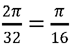


Figure 2 . The upper figure of column C2 is intensity distribution of E-field; the lower figure of column C2 is the phase distribution of E-field. - After emitting the second EM wave spectrum, the entire ring array was further rotated


Figure 2 . The upper figure of column C3 is the intensity distribution of E-field; the lower figure of column C3 is the phase distribution of E-field. - After emitting the third EM wave spectrum, the entire ring array was further rotated


Figure 2 . The upper figure of column C4 is the intensity distribution of E-field; the lower figure of column C4 is the phase distribution of E-field. - Finally, by superimposing the EM spectra of four emissions, the vortex EM wave carrying OAM mode 10 could be obtained, that is, the vortex EM wave could be synthesized from the EM waves emitted by the entire antenna array. As shown in the columns (C1+ C2+ C3+ C4) in
Figure 2 , the upper figures in the columns (C1+ C2+ C3+ C4) were the intensity distributions of E-field; the lower figures in the columns (C1+ C2+ C3+ C4) were the phase distributions of E-field. - Using traditional method UCA, 8 circularly polarized antennas were evenly distributed on a circle with a radius of 140 mm, and EM waves were emitted to synthesize vortex EM waves. The number of OAM mode met

- For the traditional method, because the OAM mode number α need to meet


- Moreover, since the number of the generated OAM mode influenced the azimuth resolution of the imaging system, the method of the present invention could also be used to increase the azimuth resolution of the imaging system, which was beneficial to realize the super-resolution imaging and that might be used for super-resolution biomedical imaging.
- In addition, compared with the traditional method, the method of the present invention could also generate vortex EM wave of high quality. The purities of the generated OAM modes were higher, which could be seen from
Figure 1 . Compared with the traditional UCA, the vortex EM wave synthesized by the method of the present invention had higher modal purity, lower imaging noise, and better imaging performance. - In summary, the present invention provided a novel SUCA method for generating vortex EM wave carrying high OAM mode. By rotating the array elements to various spatial locations, modifying their feeding phases, and superimposing the generated fields at various spatial locations, SUCA could beat the limit of space and configure more array elements to generate vortex EM waves carrying high mode OAMs. Meanwhile, due to the more synthetic array elements and smaller aperture than the traditional UCA, the purity of OAM mode was higher and it was more flexible to adjust the main lobe directions of these vortex waves carrying different OAM modes, and could generate vortex EM waves. In conclusion, with the special advantages, our proposed SUCA was potential to generate high quality vortex EM waves carrying high mode OAMs, which could be used to improve the azimuth imaging resolution. Our proposed method was potential to OAMs' application, such as super-resolution biomedical imaging, radar imaging, wireless communication and so on.
Claims (5)
- A synthetic uniform circular array, SUCA, method for synthesizing a vortex electromagnetic, EM, wave, the method comprising forming a radially placed uniform circular antenna array, UCA, with N elements, wherein N is an integer greater than 1, and then by rotating the array elements to various spatial locations, modifying their feeding phases, and superimposing the generated fields at various spatial locations, generating the vortex electromagnetic, EM, waves;wherein the method includes the following steps:(1) arranging N antenna elements on a circular ring to form the UCA;(2) feeding the N antenna elements at an initial position to emit EM waves with an initial phase;(3) by rotating the array elements to various spatial locations and modifying their feeding phases, emitting phase-controlled EM waves;(4) superimposing the EM waves emitted in step (2) and step (3) to generate vortex EM waves;wherein said step (1) also includes determining an orbital angular momentum, OAM, mode number α' of the synthesized vortex EM wave, and determining the elements number Ns of a virtual synthesized antenna array; wherein Ns=kN, k>0, and k is an integer;wherein in said step (2), the phase of the EM wave emitted by the nth element is:
 wherein the specific operation method of step (3) is: rotating the antenna array around the central axis of the ring in a set direction, and feeding the N antenna elements for emitting the EM waves from the position after rotation;wherein the antenna array is rotated a total of s times, and the angle of each rotation is
 wherein s=k-1; 1≤i≤s, and the rotation direction is clockwise or counterclockwise;the SUCA method being characterized in that the antenna element are linearly polarized antenna elements, and in that, in step (3), after each rotation of the antenna array, each antenna element is also rotated 2π/Ns around itself in a direction which
 - The method according to claim 1, characterized in that in step (1), the N antenna elements are evenly arranged on a circular ring.
- The method according to claim 1 or claim 2, characterized in that in step (3), the rotation is controlled by a precision rotating platform, and/or the radius of the circular antenna array is adjustable.
- The method according to claim 3, characterized in that the radius of the circular antenna array can be adjusted according to the OAM mode number of vortex EM wave or the requirements of imaging system.
- Use of a method according to any one of claims 1 to 4 4 in the preparation of equipment for super-resolution biomedical imaging, communication, or radar imaging.
Applications Claiming Priority (2)
| Application Number | Priority Date | Filing Date | Title |
|---|---|---|---|
| CN202010641809.8A CN111740223B (en) | 2020-07-06 | 2020-07-06 | A Method for Synthesizing Vortex Electromagnetic Fields with High Orbital Angular Momentum Mode Numbers |
| PCT/CN2020/112154 WO2022007148A1 (en) | 2020-07-06 | 2020-08-28 | Method for synthesizing vortex electromagnetic field having high orbital angular momentum mode number |
Publications (3)
| Publication Number | Publication Date |
|---|---|
| EP3965228A1 EP3965228A1 (en) | 2022-03-09 |
| EP3965228A4 EP3965228A4 (en) | 2022-06-29 |
| EP3965228B1 true EP3965228B1 (en) | 2023-03-29 |
Family
ID=72653479
Family Applications (1)
| Application Number | Title | Priority Date | Filing Date |
|---|---|---|---|
| EP20923684.3A Active EP3965228B1 (en) | 2020-07-06 | 2020-08-28 | Method for synthesizing vortex electromagnetic field having high orbital angular momentum mode number |
Country Status (7)
| Country | Link |
|---|---|
| US (1) | US11309634B2 (en) |
| EP (1) | EP3965228B1 (en) |
| JP (1) | JP7461514B2 (en) |
| KR (1) | KR102585905B1 (en) |
| CN (1) | CN111740223B (en) |
| ES (1) | ES2944472T3 (en) |
| WO (1) | WO2022007148A1 (en) |
Families Citing this family (9)
| Publication number | Priority date | Publication date | Assignee | Title |
|---|---|---|---|---|
| CN112911464B (en) * | 2021-01-18 | 2021-10-19 | 中国科学院成都生物研究所 | A method and device for generating a synthetic vortex sound field with supermode numbers |
| WO2023070485A1 (en) * | 2021-10-29 | 2023-05-04 | Qualcomm Incorporated | Orbital angular momentum communication with variable antenna number |
| CN115616477B (en) * | 2022-09-29 | 2026-04-03 | 中国电子科技集团公司第十四研究所 | A non-plane wave single-pulse angle measurement method |
| CN117250612A (en) * | 2023-09-21 | 2023-12-19 | 中国科学院成都生物研究所 | An electromagnetic field imaging method |
| CN119834876B (en) * | 2024-12-17 | 2025-11-11 | 电子科技大学 | Terahertz vortex electromagnetic wave transmission range extending method |
| CN119827848B (en) * | 2025-01-08 | 2025-09-23 | 河南大学 | Method, system, storage medium and electronic device for estimating modal purity of vortex electromagnetic waves based on main lobe ripple measurement |
| CN119535430B (en) * | 2025-01-23 | 2025-03-28 | 中国人民解放军国防科技大学 | Vortex electromagnetic wave near-field target multidimensional information measurement method, device and equipment |
| CN120854908B (en) * | 2025-09-23 | 2026-01-23 | 陕西科技大学 | Target mode vortex wave generation method of time modulation array |
| CN121091294B (en) * | 2025-09-24 | 2026-03-06 | 中国科学院声学研究所 | Three-dimensional high-resolution underwater acoustic imaging system |
Family Cites Families (22)
| Publication number | Priority date | Publication date | Assignee | Title |
|---|---|---|---|---|
| JP2006521902A (en) * | 2003-03-31 | 2006-09-28 | ライポソニックス, インコーポレイテッド | Vortex transducer |
| US20130321207A1 (en) * | 2012-05-31 | 2013-12-05 | Alcatel-Lucent Usa Inc. | Transforming precoded signals for wireless communication |
| US10228443B2 (en) * | 2012-12-02 | 2019-03-12 | Khalifa University of Science and Technology | Method and system for measuring direction of arrival of wireless signal using circular array displacement |
| EP3132558B1 (en) * | 2014-04-17 | 2021-04-07 | Rai Radiotelevisione Italiana S.p.A. | System for transmission and/or reception of signals having electromagnetic modes with orbital angular momentum, and device and method thereof |
| CN106059675B (en) * | 2016-05-24 | 2018-08-24 | 西安电子科技大学 | Circular array rotation divides shape nesting high-order vortex electromagnetic wave to generate separation method and device |
| CN106602283B (en) * | 2016-12-01 | 2019-11-26 | 西安电子科技大学 | The face high-power electromagnetic vortex H synthetic antenna based on angle phase behaviour |
| CN107004961B (en) * | 2017-01-22 | 2019-03-08 | 深圳市大疆创新科技有限公司 | Two-dimensional antenna system, method and apparatus for locating an object |
| CN107134659A (en) * | 2017-05-02 | 2017-09-05 | 西安电子科技大学 | High Gain Orbital Angular Momentum Array Antenna Based on Multilayer Dielectric Plate |
| CN107290728B (en) * | 2017-06-09 | 2020-07-10 | 清华大学 | An equivalent electromagnetic wave orbital angular momentum pulse radar detection method and system |
| US10790586B2 (en) * | 2017-06-15 | 2020-09-29 | Huawei Technologies Co., Ltd. | Adjustable stacked phase-mode feed for 2D steering of antenna arrays |
| CN107645068A (en) * | 2017-09-15 | 2018-01-30 | 中南大学 | A kind of circular array design method for rotating circular polarisation array element and producing OAM wave beams |
| CN108134756B (en) * | 2017-12-15 | 2020-06-16 | 西安电子科技大学 | Wireless Communication System Based on Vortex Electromagnetic Wave and Orthogonal Frequency Division Multiplexing |
| CN108594221A (en) * | 2018-04-27 | 2018-09-28 | 中国人民解放军国防科技大学 | Vortex Electromagnetic Wave Generation and Optimization Method Based on Concentric Ring Array |
| CN108767495B (en) * | 2018-05-24 | 2020-02-07 | 西安电子科技大学 | Vortex electromagnetic wave generating device based on super surface |
| CN108767474B (en) * | 2018-06-04 | 2020-12-18 | 中南大学 | New OAM beam generator |
| CN109167171B (en) * | 2018-07-19 | 2021-04-30 | 中国人民解放军空军工程大学 | Design method of high-efficiency transmission type vortex light generator based on PB structure |
| CN108987939B (en) * | 2018-08-14 | 2021-01-08 | 西安电子科技大学 | Vortex electromagnetic wave gathering device and wireless communication system |
| CN109755765B (en) * | 2018-12-04 | 2021-01-12 | 西安电子科技大学 | Multimodal Reconfigurable Orbital Angular Momentum Antenna Based on Uniform Circular Array |
| CN109936391B (en) | 2019-01-30 | 2020-04-14 | 西安电子科技大学 | A method for generating multimodal vortex electromagnetic waves based on a single antenna |
| CN110146953B (en) * | 2019-05-17 | 2020-11-17 | 西安理工大学 | Photonic crystal fiber generating multiple orbital angular momentum modes and design method |
| CN110444903B (en) * | 2019-07-18 | 2021-01-05 | 西安电子科技大学 | Low-sidelobe vortex beam generation method based on multi-ring array |
| CN113381794B (en) * | 2021-07-27 | 2024-07-05 | 上海瀚讯信息技术股份有限公司 | Method for adjusting OAM wave beam direction and transmitter structure |
-
2020
- 2020-07-06 CN CN202010641809.8A patent/CN111740223B/en active Active
- 2020-08-28 US US17/439,759 patent/US11309634B2/en active Active
- 2020-08-28 KR KR1020227042395A patent/KR102585905B1/en active Active
- 2020-08-28 WO PCT/CN2020/112154 patent/WO2022007148A1/en not_active Ceased
- 2020-08-28 ES ES20923684T patent/ES2944472T3/en active Active
- 2020-08-28 JP JP2022574707A patent/JP7461514B2/en active Active
- 2020-08-28 EP EP20923684.3A patent/EP3965228B1/en active Active
Also Published As
| Publication number | Publication date |
|---|---|
| CN111740223A (en) | 2020-10-02 |
| CN111740223B (en) | 2021-05-28 |
| KR102585905B1 (en) | 2023-10-05 |
| ES2944472T3 (en) | 2023-06-21 |
| US11309634B2 (en) | 2022-04-19 |
| US20220094068A1 (en) | 2022-03-24 |
| JP2023528494A (en) | 2023-07-04 |
| EP3965228A1 (en) | 2022-03-09 |
| EP3965228A4 (en) | 2022-06-29 |
| ES2944472T8 (en) | 2023-09-08 |
| JP7461514B2 (en) | 2024-04-03 |
| WO2022007148A1 (en) | 2022-01-13 |
| KR20230003243A (en) | 2023-01-05 |
Similar Documents
| Publication | Publication Date | Title |
|---|---|---|
| US11309634B2 (en) | Method for synthesizing vortex electromagnetic wave carrying high orbital angular momentum (OAM) mode | |
| Veysi et al. | Revisiting orbital angular momentum beams: Fundamentals, reflectarray generation, and novel antenna applications | |
| CN105552556B (en) | Orbital angular momentum vortex wave beam generation device and method | |
| CN105680162A (en) | Method for generating multiple orbital angular momentum beams | |
| CN110988868B (en) | Equivalent fractional order mode vortex electromagnetic wave generation and imaging method | |
| CN111541049A (en) | Method for reducing number of large-scale spherical column array elements | |
| Liu et al. | OAM mode purity improvement based on antenna array | |
| Wang et al. | Design of orbital angular momentum antennas with low sidelobes | |
| Yang et al. | Enhanced SAR imaging using multiple plane spiral orbital angular momentum beams | |
| Liu et al. | Two patch antennas for two-or four-OAM-mode generation | |
| Dong et al. | A PSO‐CVX Algorithm of Sum and Difference Beam Patterns for Time‐Modulated Antenna Array | |
| CN112751197B (en) | Phase-control vortex electromagnetic wave generation system and method | |
| Yang et al. | Subarray implementation via phase compensation in circularly polarized arrays | |
| Wang et al. | Multiple OAM beams design using the pattern product method | |
| Zeng et al. | Phase-only shaped beam synthesis for large-scale array with the guidance of beam shape | |
| Zhao et al. | Flexible secondary beamforming using holographic meta-surfaces for multi-mode vortex beam transmission in wireless communications | |
| Fu et al. | The generation of hybrid-mode orbital angular momentum beams based on holographic metasurfaces | |
| Xue et al. | Generation of OAM Beams with Multiple Modes and Multiple Directions Using Coaxial Uniform Circular Array | |
| CN105929372B (en) | The shaping method and device of the more narrow beams of MIMO radar | |
| Ma et al. | Research on the Mode Purity of Frequency-Dependent Vortex Electromagnetic Waves Generated by UCA | |
| Lin et al. | An Optimal Design of a Flat-top Beam Pattern of the OAM Wave Emitting Through a Concentric Sequentially Rotating Circular-Polarization Array | |
| Li et al. | Broadband Multiple Vortex Beam Generation Based on Pancharatnam-Berry Phase Metasurface | |
| Wu et al. | Beam Pattern Analysis of Hybrid Frequency Diverse and Phased Array | |
| CN121863062A (en) | Low-side lobe high-polymerization vortex electromagnetic wave generation method | |
| Zhang et al. | Mode-tunable Orbital Angular Momentum Beam Realized by Multi-arm Conical Helical Antenna |
Legal Events
| Date | Code | Title | Description |
|---|---|---|---|
| STAA | Information on the status of an ep patent application or granted ep patent |
Free format text: STATUS: UNKNOWN |
|
| STAA | Information on the status of an ep patent application or granted ep patent |
Free format text: STATUS: THE INTERNATIONAL PUBLICATION HAS BEEN MADE |
|
| PUAI | Public reference made under article 153(3) epc to a published international application that has entered the european phase |
Free format text: ORIGINAL CODE: 0009012 |
|
| STAA | Information on the status of an ep patent application or granted ep patent |
Free format text: STATUS: REQUEST FOR EXAMINATION WAS MADE |
|
| 17P | Request for examination filed |
Effective date: 20210915 |
|
| AK | Designated contracting states |
Kind code of ref document: A1 Designated state(s): AL AT BE BG CH CY CZ DE DK EE ES FI FR GB GR HR HU IE IS IT LI LT LU LV MC MK MT NL NO PL PT RO RS SE SI SK SM TR |
|
| REG | Reference to a national code |
Ref country code: DE Ref legal event code: R079 Free format text: PREVIOUS MAIN CLASS: H01Q0003320000 Ipc: H01Q0003300000 Ref country code: DE Ref legal event code: R079 Ref document number: 602020009325 Country of ref document: DE Free format text: PREVIOUS MAIN CLASS: H01Q0003320000 Ipc: H01Q0003300000 |
|
| A4 | Supplementary search report drawn up and despatched |
Effective date: 20220531 |
|
| RIC1 | Information provided on ipc code assigned before grant |
Ipc: H01Q 21/00 20060101ALI20220524BHEP Ipc: H01Q 1/24 20060101ALI20220524BHEP Ipc: H01Q 21/20 20060101ALI20220524BHEP Ipc: H01Q 3/30 20060101AFI20220524BHEP |
|
| RAP3 | Party data changed (applicant data changed or rights of an application transferred) |
Owner name: SHANDONG QIFENG ELECTRONIC TECHNOLGY CO., LTD. |
|
| RAP3 | Party data changed (applicant data changed or rights of an application transferred) |
Owner name: SHANDONG QIFENG ELECTRONIC TECHNOLGY CO., LTD. |
|
| RAP3 | Party data changed (applicant data changed or rights of an application transferred) |
Owner name: ZHONGKE XINGHE (SHANDONG) INTELLIGENT TECHNOLOGY CO., LTD. |
|
| DAV | Request for validation of the european patent (deleted) | ||
| DAX | Request for extension of the european patent (deleted) | ||
| INTG | Intention to grant announced |
Effective date: 20221208 |
|
| GRAS | Grant fee paid |
Free format text: ORIGINAL CODE: EPIDOSNIGR3 |
|
| STAA | Information on the status of an ep patent application or granted ep patent |
Free format text: STATUS: GRANT OF PATENT IS INTENDED |
|
| RAP1 | Party data changed (applicant data changed or rights of an application transferred) |
Owner name: CHENGDU INSTITUTE OF BIOLOGY, CHINESE ACADEMY OF SCIENCES |
|
| GRAA | (expected) grant |
Free format text: ORIGINAL CODE: 0009210 |
|
| STAA | Information on the status of an ep patent application or granted ep patent |
Free format text: STATUS: THE PATENT HAS BEEN GRANTED |
|
| AK | Designated contracting states |
Kind code of ref document: B1 Designated state(s): AL AT BE BG CH CY CZ DE DK EE ES FI FR GB GR HR HU IE IS IT LI LT LU LV MC MK MT NL NO PL PT RO RS SE SI SK SM TR |
|
| REG | Reference to a national code |
Ref country code: CH Ref legal event code: EP |
|
| REG | Reference to a national code |
Ref country code: DE Ref legal event code: R096 Ref document number: 602020009325 Country of ref document: DE |
|
| REG | Reference to a national code |
Ref country code: AT Ref legal event code: REF Ref document number: 1557320 Country of ref document: AT Kind code of ref document: T Effective date: 20230415 |
|
| REG | Reference to a national code |
Ref country code: IE Ref legal event code: FG4D |
|
| REG | Reference to a national code |
Ref country code: NL Ref legal event code: FP |
|
| RAP2 | Party data changed (patent owner data changed or rights of a patent transferred) |
Owner name: ZHONGKE XINGHE (SHANDONG) INTELIGENT TECHOLOGY CO., LTD. Owner name: CHENGDU INSTITUTE OF BIOLOGY, CHINESE ACADEMY OF SCIENCES |
|
| RAP4 | Party data changed (patent owner data changed or rights of a patent transferred) |
Owner name: ZHONGKE XINGHE (SHANDONG) INTELIGENT TECHOLOGY CO., LTD. Owner name: CHENGDU INSTITUTE OF BIOLOGY, CHINESE ACADEMY OF SCIENCES |
|
| REG | Reference to a national code |
Ref country code: NL Ref legal event code: PD Owner name: ZHONGKE XINGHE (SHANDONG) INTELIGENT TECHOLOGY CO., LTD.; CN Free format text: DETAILS ASSIGNMENT: CHANGE OF OWNER(S), ASSIGNMENT; FORMER OWNER NAME: CHENGDU INSTITUTE OF BIOLOGY, CHINESE ACADEMY OF SCIENCES Effective date: 20230511 |
|
| REG | Reference to a national code |
Ref country code: CH Ref legal event code: PK Free format text: BERICHTIGUNGEN |
|
| REG | Reference to a national code |
Ref country code: ES Ref legal event code: FG2A Ref document number: 2944472 Country of ref document: ES Kind code of ref document: T3 Effective date: 20230621 |
|
| REG | Reference to a national code |
Ref country code: LT Ref legal event code: MG9D |
|
| REG | Reference to a national code |
Ref country code: NL Ref legal event code: HC Owner name: ZHONGKE XINGHE (SHANDONG) INTELLIGENT TECHOLOGY CO., LTD.; CN Free format text: DETAILS ASSIGNMENT: CHANGE OF OWNER(S), CHANGE OF OWNER(S) NAME; FORMER OWNER NAME: ZHONGKE XINGHE (SHANDONG) INTELIGENT TECHOLOGY CO., LTD. Effective date: 20230705 |
|
| REG | Reference to a national code |
Ref country code: SE Ref legal event code: TRGR |
|
| PG25 | Lapsed in a contracting state [announced via postgrant information from national office to epo] |
Ref country code: RS Free format text: LAPSE BECAUSE OF FAILURE TO SUBMIT A TRANSLATION OF THE DESCRIPTION OR TO PAY THE FEE WITHIN THE PRESCRIBED TIME-LIMIT Effective date: 20230329 Ref country code: NO Free format text: LAPSE BECAUSE OF FAILURE TO SUBMIT A TRANSLATION OF THE DESCRIPTION OR TO PAY THE FEE WITHIN THE PRESCRIBED TIME-LIMIT Effective date: 20230629 Ref country code: LV Free format text: LAPSE BECAUSE OF FAILURE TO SUBMIT A TRANSLATION OF THE DESCRIPTION OR TO PAY THE FEE WITHIN THE PRESCRIBED TIME-LIMIT Effective date: 20230329 Ref country code: LT Free format text: LAPSE BECAUSE OF FAILURE TO SUBMIT A TRANSLATION OF THE DESCRIPTION OR TO PAY THE FEE WITHIN THE PRESCRIBED TIME-LIMIT Effective date: 20230329 Ref country code: HR Free format text: LAPSE BECAUSE OF FAILURE TO SUBMIT A TRANSLATION OF THE DESCRIPTION OR TO PAY THE FEE WITHIN THE PRESCRIBED TIME-LIMIT Effective date: 20230329 |
|
| REG | Reference to a national code |
Ref country code: NL Ref legal event code: HC Owner name: ZHONGKE XINGHE (SHANDONG) INTELLIGENT TECHNOLOGY CO., LTD.; CN Free format text: DETAILS ASSIGNMENT: CHANGE OF OWNER(S), CHANGE OF OWNER(S) NAME; FORMER OWNER NAME: ZHONGKE XINGHE (SHANDONG) INTELLIGENT TECHOLOGY CO., LTD. Effective date: 20230720 |
|
| REG | Reference to a national code |
Ref country code: AT Ref legal event code: MK05 Ref document number: 1557320 Country of ref document: AT Kind code of ref document: T Effective date: 20230329 |
|
| PG25 | Lapsed in a contracting state [announced via postgrant information from national office to epo] |
Ref country code: GR Free format text: LAPSE BECAUSE OF FAILURE TO SUBMIT A TRANSLATION OF THE DESCRIPTION OR TO PAY THE FEE WITHIN THE PRESCRIBED TIME-LIMIT Effective date: 20230630 Ref country code: FI Free format text: LAPSE BECAUSE OF FAILURE TO SUBMIT A TRANSLATION OF THE DESCRIPTION OR TO PAY THE FEE WITHIN THE PRESCRIBED TIME-LIMIT Effective date: 20230329 |
|
| PG25 | Lapsed in a contracting state [announced via postgrant information from national office to epo] |
Ref country code: SM Free format text: LAPSE BECAUSE OF FAILURE TO SUBMIT A TRANSLATION OF THE DESCRIPTION OR TO PAY THE FEE WITHIN THE PRESCRIBED TIME-LIMIT Effective date: 20230329 Ref country code: RO Free format text: LAPSE BECAUSE OF FAILURE TO SUBMIT A TRANSLATION OF THE DESCRIPTION OR TO PAY THE FEE WITHIN THE PRESCRIBED TIME-LIMIT Effective date: 20230329 Ref country code: PT Free format text: LAPSE BECAUSE OF FAILURE TO SUBMIT A TRANSLATION OF THE DESCRIPTION OR TO PAY THE FEE WITHIN THE PRESCRIBED TIME-LIMIT Effective date: 20230731 Ref country code: EE Free format text: LAPSE BECAUSE OF FAILURE TO SUBMIT A TRANSLATION OF THE DESCRIPTION OR TO PAY THE FEE WITHIN THE PRESCRIBED TIME-LIMIT Effective date: 20230329 Ref country code: AT Free format text: LAPSE BECAUSE OF FAILURE TO SUBMIT A TRANSLATION OF THE DESCRIPTION OR TO PAY THE FEE WITHIN THE PRESCRIBED TIME-LIMIT Effective date: 20230329 |
|
| PG25 | Lapsed in a contracting state [announced via postgrant information from national office to epo] |
Ref country code: SK Free format text: LAPSE BECAUSE OF FAILURE TO SUBMIT A TRANSLATION OF THE DESCRIPTION OR TO PAY THE FEE WITHIN THE PRESCRIBED TIME-LIMIT Effective date: 20230329 Ref country code: PL Free format text: LAPSE BECAUSE OF FAILURE TO SUBMIT A TRANSLATION OF THE DESCRIPTION OR TO PAY THE FEE WITHIN THE PRESCRIBED TIME-LIMIT Effective date: 20230329 Ref country code: IS Free format text: LAPSE BECAUSE OF FAILURE TO SUBMIT A TRANSLATION OF THE DESCRIPTION OR TO PAY THE FEE WITHIN THE PRESCRIBED TIME-LIMIT Effective date: 20230729 |
|
| REG | Reference to a national code |
Ref country code: DE Ref legal event code: R097 Ref document number: 602020009325 Country of ref document: DE |
|
| PG25 | Lapsed in a contracting state [announced via postgrant information from national office to epo] |
Ref country code: DK Free format text: LAPSE BECAUSE OF FAILURE TO SUBMIT A TRANSLATION OF THE DESCRIPTION OR TO PAY THE FEE WITHIN THE PRESCRIBED TIME-LIMIT Effective date: 20230329 Ref country code: CZ Free format text: LAPSE BECAUSE OF FAILURE TO SUBMIT A TRANSLATION OF THE DESCRIPTION OR TO PAY THE FEE WITHIN THE PRESCRIBED TIME-LIMIT Effective date: 20230329 |
|
| PLBE | No opposition filed within time limit |
Free format text: ORIGINAL CODE: 0009261 |
|
| STAA | Information on the status of an ep patent application or granted ep patent |
Free format text: STATUS: NO OPPOSITION FILED WITHIN TIME LIMIT |
|
| 26N | No opposition filed |
Effective date: 20240103 |
|
| PG25 | Lapsed in a contracting state [announced via postgrant information from national office to epo] |
Ref country code: MC Free format text: LAPSE BECAUSE OF FAILURE TO SUBMIT A TRANSLATION OF THE DESCRIPTION OR TO PAY THE FEE WITHIN THE PRESCRIBED TIME-LIMIT Effective date: 20230329 |
|
| PG25 | Lapsed in a contracting state [announced via postgrant information from national office to epo] |
Ref country code: MC Free format text: LAPSE BECAUSE OF FAILURE TO SUBMIT A TRANSLATION OF THE DESCRIPTION OR TO PAY THE FEE WITHIN THE PRESCRIBED TIME-LIMIT Effective date: 20230329 |
|
| PG25 | Lapsed in a contracting state [announced via postgrant information from national office to epo] |
Ref country code: LU Free format text: LAPSE BECAUSE OF NON-PAYMENT OF DUE FEES Effective date: 20230828 |
|
| PG25 | Lapsed in a contracting state [announced via postgrant information from national office to epo] |
Ref country code: LU Free format text: LAPSE BECAUSE OF NON-PAYMENT OF DUE FEES Effective date: 20230828 |
|
| PG25 | Lapsed in a contracting state [announced via postgrant information from national office to epo] |
Ref country code: SI Free format text: LAPSE BECAUSE OF FAILURE TO SUBMIT A TRANSLATION OF THE DESCRIPTION OR TO PAY THE FEE WITHIN THE PRESCRIBED TIME-LIMIT Effective date: 20230329 |
|
| REG | Reference to a national code |
Ref country code: BE Ref legal event code: MM Effective date: 20230831 |
|
| REG | Reference to a national code |
Ref country code: IE Ref legal event code: MM4A |
|
| PG25 | Lapsed in a contracting state [announced via postgrant information from national office to epo] |
Ref country code: SI Free format text: LAPSE BECAUSE OF FAILURE TO SUBMIT A TRANSLATION OF THE DESCRIPTION OR TO PAY THE FEE WITHIN THE PRESCRIBED TIME-LIMIT Effective date: 20230329 |
|
| PG25 | Lapsed in a contracting state [announced via postgrant information from national office to epo] |
Ref country code: IE Free format text: LAPSE BECAUSE OF NON-PAYMENT OF DUE FEES Effective date: 20230828 |
|
| PG25 | Lapsed in a contracting state [announced via postgrant information from national office to epo] |
Ref country code: IE Free format text: LAPSE BECAUSE OF NON-PAYMENT OF DUE FEES Effective date: 20230828 |
|
| PG25 | Lapsed in a contracting state [announced via postgrant information from national office to epo] |
Ref country code: BE Free format text: LAPSE BECAUSE OF NON-PAYMENT OF DUE FEES Effective date: 20230831 |
|
| PG25 | Lapsed in a contracting state [announced via postgrant information from national office to epo] |
Ref country code: BG Free format text: LAPSE BECAUSE OF FAILURE TO SUBMIT A TRANSLATION OF THE DESCRIPTION OR TO PAY THE FEE WITHIN THE PRESCRIBED TIME-LIMIT Effective date: 20230329 |
|
| PG25 | Lapsed in a contracting state [announced via postgrant information from national office to epo] |
Ref country code: BG Free format text: LAPSE BECAUSE OF FAILURE TO SUBMIT A TRANSLATION OF THE DESCRIPTION OR TO PAY THE FEE WITHIN THE PRESCRIBED TIME-LIMIT Effective date: 20230329 |
|
| PG25 | Lapsed in a contracting state [announced via postgrant information from national office to epo] |
Ref country code: CY Free format text: LAPSE BECAUSE OF FAILURE TO SUBMIT A TRANSLATION OF THE DESCRIPTION OR TO PAY THE FEE WITHIN THE PRESCRIBED TIME-LIMIT; INVALID AB INITIO Effective date: 20200828 |
|
| PG25 | Lapsed in a contracting state [announced via postgrant information from national office to epo] |
Ref country code: HU Free format text: LAPSE BECAUSE OF FAILURE TO SUBMIT A TRANSLATION OF THE DESCRIPTION OR TO PAY THE FEE WITHIN THE PRESCRIBED TIME-LIMIT; INVALID AB INITIO Effective date: 20200828 |
|
| PGFP | Annual fee paid to national office [announced via postgrant information from national office to epo] |
Ref country code: NL Payment date: 20250826 Year of fee payment: 6 |
|
| PGFP | Annual fee paid to national office [announced via postgrant information from national office to epo] |
Ref country code: ES Payment date: 20250902 Year of fee payment: 6 |
|
| PGFP | Annual fee paid to national office [announced via postgrant information from national office to epo] |
Ref country code: DE Payment date: 20250828 Year of fee payment: 6 |
|
| PGFP | Annual fee paid to national office [announced via postgrant information from national office to epo] |
Ref country code: IT Payment date: 20250827 Year of fee payment: 6 |
|
| PGFP | Annual fee paid to national office [announced via postgrant information from national office to epo] |
Ref country code: GB Payment date: 20250827 Year of fee payment: 6 |
|
| PGFP | Annual fee paid to national office [announced via postgrant information from national office to epo] |
Ref country code: FR Payment date: 20250826 Year of fee payment: 6 |
|
| PGFP | Annual fee paid to national office [announced via postgrant information from national office to epo] |
Ref country code: CH Payment date: 20250901 Year of fee payment: 6 Ref country code: SE Payment date: 20250827 Year of fee payment: 6 |
|
| PG25 | Lapsed in a contracting state [announced via postgrant information from national office to epo] |
Ref country code: TR Free format text: LAPSE BECAUSE OF FAILURE TO SUBMIT A TRANSLATION OF THE DESCRIPTION OR TO PAY THE FEE WITHIN THE PRESCRIBED TIME-LIMIT Effective date: 20230329 |