EP3964640B1 - Clothing management apparatus and control method therefor - Google Patents
Clothing management apparatus and control method therefor Download PDFInfo
- Publication number
- EP3964640B1 EP3964640B1 EP20839871.9A EP20839871A EP3964640B1 EP 3964640 B1 EP3964640 B1 EP 3964640B1 EP 20839871 A EP20839871 A EP 20839871A EP 3964640 B1 EP3964640 B1 EP 3964640B1
- Authority
- EP
- European Patent Office
- Prior art keywords
- damper
- chamber
- humidity
- blower fan
- care apparatus
- Prior art date
- Legal status (The legal status is an assumption and is not a legal conclusion. Google has not performed a legal analysis and makes no representation as to the accuracy of the status listed.)
- Active
Links
Images








Classifications
-
- D—TEXTILES; PAPER
- D06—TREATMENT OF TEXTILES OR THE LIKE; LAUNDERING; FLEXIBLE MATERIALS NOT OTHERWISE PROVIDED FOR
- D06F—LAUNDERING, DRYING, IRONING, PRESSING OR FOLDING TEXTILE ARTICLES
- D06F58/00—Domestic laundry dryers
- D06F58/10—Drying cabinets or drying chambers having heating or ventilating means
-
- D—TEXTILES; PAPER
- D06—TREATMENT OF TEXTILES OR THE LIKE; LAUNDERING; FLEXIBLE MATERIALS NOT OTHERWISE PROVIDED FOR
- D06F—LAUNDERING, DRYING, IRONING, PRESSING OR FOLDING TEXTILE ARTICLES
- D06F58/00—Domestic laundry dryers
- D06F58/32—Control of operations performed in domestic laundry dryers
- D06F58/34—Control of operations performed in domestic laundry dryers characterised by the purpose or target of the control
- D06F58/36—Control of operational steps, e.g. for optimisation or improvement of operational steps depending on the condition of the laundry
- D06F58/38—Control of operational steps, e.g. for optimisation or improvement of operational steps depending on the condition of the laundry of drying, e.g. to achieve the target humidity
-
- D—TEXTILES; PAPER
- D06—TREATMENT OF TEXTILES OR THE LIKE; LAUNDERING; FLEXIBLE MATERIALS NOT OTHERWISE PROVIDED FOR
- D06F—LAUNDERING, DRYING, IRONING, PRESSING OR FOLDING TEXTILE ARTICLES
- D06F58/00—Domestic laundry dryers
- D06F58/30—Drying processes
-
- D—TEXTILES; PAPER
- D06—TREATMENT OF TEXTILES OR THE LIKE; LAUNDERING; FLEXIBLE MATERIALS NOT OTHERWISE PROVIDED FOR
- D06F—LAUNDERING, DRYING, IRONING, PRESSING OR FOLDING TEXTILE ARTICLES
- D06F2103/00—Parameters monitored or detected for the control of domestic laundry washing machines, washer-dryers or laundry dryers
-
- D—TEXTILES; PAPER
- D06—TREATMENT OF TEXTILES OR THE LIKE; LAUNDERING; FLEXIBLE MATERIALS NOT OTHERWISE PROVIDED FOR
- D06F—LAUNDERING, DRYING, IRONING, PRESSING OR FOLDING TEXTILE ARTICLES
- D06F2103/00—Parameters monitored or detected for the control of domestic laundry washing machines, washer-dryers or laundry dryers
- D06F2103/28—Air properties
- D06F2103/32—Temperature
-
- D—TEXTILES; PAPER
- D06—TREATMENT OF TEXTILES OR THE LIKE; LAUNDERING; FLEXIBLE MATERIALS NOT OTHERWISE PROVIDED FOR
- D06F—LAUNDERING, DRYING, IRONING, PRESSING OR FOLDING TEXTILE ARTICLES
- D06F2103/00—Parameters monitored or detected for the control of domestic laundry washing machines, washer-dryers or laundry dryers
- D06F2103/28—Air properties
- D06F2103/34—Humidity
-
- D—TEXTILES; PAPER
- D06—TREATMENT OF TEXTILES OR THE LIKE; LAUNDERING; FLEXIBLE MATERIALS NOT OTHERWISE PROVIDED FOR
- D06F—LAUNDERING, DRYING, IRONING, PRESSING OR FOLDING TEXTILE ARTICLES
- D06F2103/00—Parameters monitored or detected for the control of domestic laundry washing machines, washer-dryers or laundry dryers
- D06F2103/56—Parameters monitored or detected for the control of domestic laundry washing machines, washer-dryers or laundry dryers related to air ducts, e.g. position of flow diverters
-
- D—TEXTILES; PAPER
- D06—TREATMENT OF TEXTILES OR THE LIKE; LAUNDERING; FLEXIBLE MATERIALS NOT OTHERWISE PROVIDED FOR
- D06F—LAUNDERING, DRYING, IRONING, PRESSING OR FOLDING TEXTILE ARTICLES
- D06F2105/00—Systems or parameters controlled or affected by the control systems of washing machines, washer-dryers or laundry dryers
- D06F2105/16—Air properties
- D06F2105/22—Humidity
-
- D—TEXTILES; PAPER
- D06—TREATMENT OF TEXTILES OR THE LIKE; LAUNDERING; FLEXIBLE MATERIALS NOT OTHERWISE PROVIDED FOR
- D06F—LAUNDERING, DRYING, IRONING, PRESSING OR FOLDING TEXTILE ARTICLES
- D06F2105/00—Systems or parameters controlled or affected by the control systems of washing machines, washer-dryers or laundry dryers
- D06F2105/26—Heat pumps
-
- D—TEXTILES; PAPER
- D06—TREATMENT OF TEXTILES OR THE LIKE; LAUNDERING; FLEXIBLE MATERIALS NOT OTHERWISE PROVIDED FOR
- D06F—LAUNDERING, DRYING, IRONING, PRESSING OR FOLDING TEXTILE ARTICLES
- D06F2105/00—Systems or parameters controlled or affected by the control systems of washing machines, washer-dryers or laundry dryers
- D06F2105/30—Blowers
-
- D—TEXTILES; PAPER
- D06—TREATMENT OF TEXTILES OR THE LIKE; LAUNDERING; FLEXIBLE MATERIALS NOT OTHERWISE PROVIDED FOR
- D06F—LAUNDERING, DRYING, IRONING, PRESSING OR FOLDING TEXTILE ARTICLES
- D06F2105/00—Systems or parameters controlled or affected by the control systems of washing machines, washer-dryers or laundry dryers
- D06F2105/32—Air flow control means
-
- D—TEXTILES; PAPER
- D06—TREATMENT OF TEXTILES OR THE LIKE; LAUNDERING; FLEXIBLE MATERIALS NOT OTHERWISE PROVIDED FOR
- D06F—LAUNDERING, DRYING, IRONING, PRESSING OR FOLDING TEXTILE ARTICLES
- D06F34/00—Details of control systems for washing machines, washer-dryers or laundry dryers
- D06F34/14—Arrangements for detecting or measuring specific parameters
- D06F34/26—Condition of the drying air, e.g. air humidity or temperature
-
- D—TEXTILES; PAPER
- D06—TREATMENT OF TEXTILES OR THE LIKE; LAUNDERING; FLEXIBLE MATERIALS NOT OTHERWISE PROVIDED FOR
- D06F—LAUNDERING, DRYING, IRONING, PRESSING OR FOLDING TEXTILE ARTICLES
- D06F58/00—Domestic laundry dryers
- D06F58/20—General details of domestic laundry dryers
- D06F58/206—Heat pump arrangements
-
- D—TEXTILES; PAPER
- D06—TREATMENT OF TEXTILES OR THE LIKE; LAUNDERING; FLEXIBLE MATERIALS NOT OTHERWISE PROVIDED FOR
- D06F—LAUNDERING, DRYING, IRONING, PRESSING OR FOLDING TEXTILE ARTICLES
- D06F58/00—Domestic laundry dryers
- D06F58/32—Control of operations performed in domestic laundry dryers
- D06F58/34—Control of operations performed in domestic laundry dryers characterised by the purpose or target of the control
- D06F58/48—Control of the energy consumption
-
- Y—GENERAL TAGGING OF NEW TECHNOLOGICAL DEVELOPMENTS; GENERAL TAGGING OF CROSS-SECTIONAL TECHNOLOGIES SPANNING OVER SEVERAL SECTIONS OF THE IPC; TECHNICAL SUBJECTS COVERED BY FORMER USPC CROSS-REFERENCE ART COLLECTIONS [XRACs] AND DIGESTS
- Y02—TECHNOLOGIES OR APPLICATIONS FOR MITIGATION OR ADAPTATION AGAINST CLIMATE CHANGE
- Y02B—CLIMATE CHANGE MITIGATION TECHNOLOGIES RELATED TO BUILDINGS, e.g. HOUSING, HOUSE APPLIANCES OR RELATED END-USER APPLICATIONS
- Y02B40/00—Technologies aiming at improving the efficiency of home appliances, e.g. induction cooking or efficient technologies for refrigerators, freezers or dish washers
Definitions
- the invention relates to a clothes care apparatus capable of performing a drying cycle of clothes, removing wrinkles from the clothes and capable of removing dust attached to clothes or smell of the clothes.
- a clothes care apparatus is a type of device performing clothes care such as drying wet clothes, removing dust attached to the clothes or eliminating remaining odors in the clothes and removing wrinkles from the clothes.
- the clothes care apparatus has a vapor compression heat pump system and is capable of drying object through the air circulation.
- the operation of the heat pump is performed until the end of drying is identified.
- This method may be effective when an object to be dried has a large amount of moisture.
- this method may have the poor drying efficiency with respect to the power consumption.
- a clothes care apparatus capable of efficiently managing power by drying an object to be dried using the outside air and controlling a heat exchanger, and a control method thereof.
- the controller may close the first damper and the second damper, and perform driving of the blower fan and the heat exchanger, and when the internal humidity of the chamber is less than a reference humidity and the internal temperature of the chamber is higher than or equal to a reference temperature, the controller may determine that the predetermined condition is satisfied.
- the blower fan may include a first blower fan configured to generate the air flow from the chamber to the outside, and the controller may directly introduce the outside air to the chamber by driving the first blower fan.
- the controller may drive the compressor, open the first damper and the second damper, and drive the blower fan so as to generate the air flow in which air flows from the second damper to the chamber through the heat exchanger.
- the blower fan may include a second blower fan configured to generate the air flow from the outside to the heat exchanger.
- the controller may allow the compressor to drive at a predetermined frequency, such as a minimum frequency.
- the minimum frequency may correspond to a frequency that is applied to consume power less than power that is consumed by the compressor before the predetermined condition is satisfied.
- the controller may close the first damper and the second damper and drive the blower fan and the compressor.
- the sensor portion may be provided inside the chamber, and the controller may open the first damper and the second damper at a start timing of the drying cycle and determine the external absolute humidity based on a temperature and humidity of the inside of the clothe care apparatus.
- the sensor portion may include an internal sensor provided in the inside of the clothes care apparatus and an external sensor provided on the outside of the clothes care apparatus, and the controller may determine the internal absolute humidity based on a temperature and humidity obtained by the internal sensor, and the controller may determine the external absolute humidity based on a temperature and humidity obtained by the external sensor.
- the internal humidity may correspond to the absolute humidity of the inside of the chamber
- the external humidity may correspond to the absolute humidity of the outside of the clothes care apparatus.
- Performing a drying cycle by using inside air through a heat exchanger may include closing the first damper and the second damper, and performing driving of the blower fan and the heat exchanger, and when the internal humidity of the chamber is less than a reference humidity and the internal temperature of the chamber is higher than or equal to a reference temperature, determining that the predetermined condition is satisfied.
- the blower fan may include a first blower fan configured to generate the air flow from the chamber to the outside, and controlling at least one blower fan may include directly introducing the outside air to the chamber by driving the first blower fan.
- Allowing a first damper and a second damper to be opened or closed and controlling driving of the heat exchanger and at least one blower fan by comparing the internal humidity with the external humidity may include, when the external humidity exceeds the internal humidity, driving the compressor, opening the first damper and the second damper, and driving the blower fan, thereby generating an air flow in which air flows from the second damper to the chamber through the heat exchanger.
- the blower fan may include a second blower fan configured to generate the air flow from the outside to the heat exchanger.
- Controlling the compressor may include allowing the compressor to drive at a predetermined frequency such as a minimum frequency.
- the minimum frequency may correspond to a frequency that is applied to consume the power less than the power that is consumed by the compressor before the predetermined condition is satisfied.
- Allowing a first damper and a second damper to be opened or closed and controlling driving of the heat exchanger and at least one blower fan by comparing the internal humidity with the external humidity may include, when the external humidity exceeds a predetermined value, closing the first damper and the second damper and driving the blower fan and the compressor.
- Obtaining a temperature and humidity of the inside and the outside of a chamber may include opening the first damper and the second damper at a start timing of the drying cycle, and determining the external absolute humidity based on a temperature and humidity of the inside of the clothe care apparatus.
- Obtaining a temperature and humidity of the inside and the outside of a chamber may include determining the internal absolute humidity based on a temperature and humidity obtained by an internal sensor, and determining the external absolute humidity based on a temperature and humidity obtained by an external sensor.
- the internal humidity may correspond to the absolute humidity of the inside of the chamber
- the external humidity may correspond to the absolute humidity of the outside of the clothes care apparatus.
- Embodiments of the invention are set out in the dependent claims. In the following, embodiments that do not fall within the scope of the claims relate to exemplary embodiments of the disclosure that are not covered by the claimed invention.
- various functions described below can be implemented or supported by one or more computer programs, each of which is formed from computer readable program code and embodied in a computer readable medium.
- application and “program” refer to one or more computer programs, software components, sets of instructions, procedures, functions, objects, classes, instances, related data, or a portion thereof adapted for implementation in a suitable computer readable program code.
- computer readable program code includes any type of computer code, including source code, object code, and executable code.
- computer readable medium includes any type of medium capable of being accessed by a computer, such as read only memory (ROM), random access memory (RAM), a hard disk drive, a compact disc (CD), a digital video disc (DVD), or any other type of memory.
- ROM read only memory
- RAM random access memory
- CD compact disc
- DVD digital video disc
- a "non-transitory” computer readable medium excludes wired, wireless, optical, or other communication links that transport transitory electrical or other signals.
- a non-transitory computer readable medium includes media where data can be permanently stored and media where data can be stored and later overwritten, such as a rewritable optical disc or an erasable memory device.
- FIGS. 1 through 14 discussed below, and the various embodiments used to describe the present disclosure are by way of illustration only and should not be construed in any way to limit the scope of the disclosure, which is defined by the claims. Those skilled in the art will understand that the principles of the present disclosure may be implemented in any suitably arranged system or device.
- Terms such as “unit”, “portion”, “block”, “member” and “module” may be embodied as hardware or software.
- “unit”, “portion”, “block”, “member” and “module” may indicate a unit for processing at least one function or operation.
- terms such as “unit”, “portion”, “block”, “member” and “module” may refer to at least one process processed by at least one software or process stored in at least one hardware, circuit, and a memory.
- “unit”, “portion”, “block”, “member” and “module” may include at least one component.
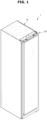
- FIG. 1 illustrates a view of a clothes care apparatus according to an embodiment of the disclosure
- FIG. 2 is a view illustrating a state in which a door of the clothes care apparatus according to an embodiment of the disclosure is opened
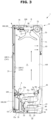
- FIG. 3 illustrates a side cross-sectional view of the clothes care apparatus according to an embodiment of the disclosure
- FIG. 4 is an exploded view illustrating the clothes care apparatus according to an embodiment of the disclosure.
- a clothes care apparatus 1 includes a body 10 forming an external appearance, a door 20 rotatably coupled to body 10, a chamber 11 provided inside the body 10 to allow clothes to be placed and to be managed, a clothes support member 50 provided inside the chamber 11 to allow clothes to be hung thereon, and a machine room 13 provided with a heat exchanger 30 configured to dehumidify or heat air in the chamber 11.
- the body 10 has the chamber 11 formed therein, and may have a hexahedron shape having an open one surface.
- An opening 10a may be formed on the front surface of the body 10.
- the door 20 is rotatably coupled to the opening 10a of the body 10 to open and close the chamber 11.
- the door 20 may be installed through a connecting member such as a hinge and a link.
- the chamber 11 forms a space in which clothes are accommodated.
- the chamber 11 may be formed by including an upper surface 10b, a lower surface 10c, a left side surface 10d, a right side surface 10e, and a rear surface 10f provided inside the body 10.
- the front surface of the chamber 11 is formed to be open. Therefore, the opening of the chamber 11 may also be opened and closed by the door 20 configured to open and close the opening 10a of the body 10.
- a discharge bracket 16 installed in a position corresponding to a discharge flow path 120 of the door 20 described later may be provided on an upper end of the opening 10a of the body 10.
- the discharge bracket 16 may include a plurality of slits 16a arranged in accordance with the discharge flow path 120 of the door 20.
- the clothes support member 50 configured to allow clothes to be hung and to be supported, is provided in the chamber 11.
- the clothes support member 50 may be installed on the upper surface 10b of the chamber 11.
- the clothes support member 50 may be removably installed in the chamber 11.
- One or more clothes support member 50 may be provided.
- the clothes support member 50 may be formed in a clothes hanger shape to allow clothes to be hung.
- the clothes support member 50 is configured to allow air to flow therein. Dust or foreign substances on the clothes may be removed by the air supplied into the clothes support member 50.
- the clothes support member 50 may be provided with an air hole 51 for supplying air to the clothes.
- the air hole is arranged on an upper end of the clothes support member 50, and the air discharged through the air hole is supplied to the inside and the outside of the clothes, but is not limited thereto.
- the air hole may be formed in various sizes at various positions to inject air into the clothes in various directions.
- the chamber 11 may include a first airflow inlet 11a, a second airflow inlet, a first airflow outlet 11b, a second airflow outlet 12b and a steam outlet.
- the first airflow inlet 11a and the first airflow outlet 11b may be formed on the lower surface 10c of the chamber 11.
- the first airflow inlet 11a may be arranged in a front portion of the lower surface 10c of the chamber 11.
- the first airflow outlet 11b may be arranged in a rear portion of the lower surface 10c of the chamber 11.
- the first airflow inlet 11a and the first airflow outlet 11b may be arranged adjacent to each other.
- the steam outlet may be arranged in a lower portion of the rear surface 10f of the chamber 11.
- the steam outlet may be arranged in an upper side of the first airflow outlet 11b.
- the second airflow inlet may be formed at an upper portion of the rear surface 10f of the chamber 11.
- the second airflow outlet 12b may be formed at a substantially central portion of the upper surface 10b of the chamber 11.
- the second airflow inlet and the second airflow outlet 12b may be arranged adjacent to each other.
- the second airflow outlet 12b of the chamber 11 may be connected to the clothes support member 50. Air discharged through the second airflow outlet 12b may be delivered to the clothes support member 50 through the air hole 51 and then delivered to the clothes hung on the clothes support member 50.
- a water drain tank 15a and a water supply tank 15b removably installed to the body 10 may be provided.
- the water drain tank 15a and the water supply tank 15b may be arranged under the chamber 11.
- the water drain tank 15a may be configured to easily treat condensed water.
- the water supply tank 15b may store water needed for a steam generation device 40 to generate steam described later. That is, water of the water supply tank 15b is supplied to the steam generation device 40 and then used to generate steam.
- the water supply tank 15b may be removably mounted to the body 10 so as to easily supplement water.
- the water drain tank 15a and the water supply tank 15b may be provided in front of the machine room 13.
- the machine room 13 is provided in the lower portion of the body 10.
- the machine room 13 is provided under the chamber 11.
- the machine room 13 may include the heat exchanger 30 configured to dehumidify and heat air in the chamber 11 as needed.
- a second blower fan 32, the heat exchanger 30, and the steam generation device 40 may be arranged inside the machine room 13.
- the heat exchanger 30 is installed to supply hot air into the chamber 11.
- the heat exchanger 30 includes an evaporator 33, a compressor 35 and a condenser 34 through which a refrigerant circulates, and the heat exchanger 30 is configured to dehumidify and heat the air.
- the refrigerant evaporates in the evaporator 33 of the heat exchanger 30 so as to condense and remove moisture in the air.
- the refrigerant is passed through the compressor 35 and then condensed in the condenser 34, the latent heat is released toward the ambient air to heat the ambient air.
- the evaporator 33 and the condenser 34 function as heat exchangers, and the air, which flows into the machine room 13 by the second blower fan 32, is dehumidified and heated while passing through the evaporator 33 and the condenser 34 sequentially.
- the heat exchanger 30 installed in the machine room 13 may include a first duct 31 configured to connect the evaporator 33, the condenser 34 and the second blower fan 32, and the first duct 31 may be connected to the chamber 11, thereby forming a first circulation flow path 39 circulating between the chamber 11 and the first duct 31.
- the first duct 31 may be connected to the first airflow inlet 11a and the first airflow outlet 11b of the chamber 11. One end of the first duct 31 may be connected to the first airflow inlet 11a of the chamber 11, and the other end of the first duct 31 may be connected to the first airflow outlet 11b of the chamber 11. A first duct inlet 31a of the first duct 31 may be connected to the first airflow inlet 11a and a first duct outlet 31b may be connected to the first airflow outlet 11b.
- Air in the chamber 11 may flow into the first duct 31 through the first airflow inlet 11a.
- the flowing air may be dehumidified and then discharged to the chamber 11 again, through the first airflow outlet 11b.
- the first airflow inlet is arranged in the front portion of the chamber and the first airflow outlet is arranged in the rear portion of the chamber, but is not limited thereto. Therefore, a location of the airflow inlet and airflow outlet may vary, as needed.
- the first duct 31 is configured to dehumidify the air flowing through the first airflow inlet 11a, and to discharge the dehumidified air to the first airflow outlet 11b.
- the second blower fan 32 is installed on the first duct 31 to suck the air of the chamber 11 into the first duct 31.
- the machine room 13 may further include the steam generation device 40 configured to generate steam by receiving water from the water supply tank 15b.
- the steam generation device 40 may be arranged in the machine room 13.
- the steam generation device 40 may include a steam generator 41 connected to the water supply tank 15b to receive the water so as to generate steam, and a steam supply pipe configured to guide the generated steam to a steam injector 42.
- the steam injector 42 may be arranged in a lower portion of the rear surface of the chamber 11.
- a heater (not shown) may be installed inside the steam generator 41 to heat water.
- the chamber 11 may include a first blower fan 72 configured to move the air in the chamber 11.
- the chamber 11 may include a second duct 71, and the first blower fan 72 may be installed in the second duct 71.
- the second duct 71 may communicates with the chamber 11, and accordingly, a second circulation flow path 70 configure to allow air to circulate between the chamber 11 and the second duct 71 may be formed.
- the first blower fan 72 may be arranged on the second circulation flow path 70.
- the second duct 71 may be formed behind the second airflow inlet of the chamber 11.
- the second duct 71 may be provided at the upper rear of the chamber 11, and may include a filter member 60 therein.
- the second duct 71 may be coupled to a top cover 80 arranged above the chamber 11.
- the second duct 71 may be coupled to the top cover 80 and the first blower fan 72 may be installed therein.
- the first blower fan 72 may be arranged at the upper rear of the chamber 11.
- the first blower fan 72 may include a blower motor 72a configured to generate a rotational force, and at least one fan 72b configured to rotate by the blower motor.
- the fan 72b may be accommodated by a fan case 72c.
- the fan case 72c may be coupled to a duct bracket 74 provided on the upper surface 10b of the chamber 11. At least one duct hole 74a is formed in the duct bracket 74, and the first blower fan 72 is coupled to the at least one duct hole 74a to supply air of the second duct 71 to the second airflow outlet 12b of the second duct 71.
- the second duct 71 may be connected to the second airflow inlet and the second airflow outlet 12b of the chamber 11. One end of the second duct 71 may be connected to the second airflow inlet of the chamber 11, and the other end of the second duct 71 may be connected to the second airflow outlet 12b. A second duct inlet of the second duct 71 may be connected to the second airflow inlet and a second duct outlet 71b may be connected to the second airflow outlet 12b.
- the second airflow outlet 12b of the chamber 11 may be formed on a position corresponding to the second duct outlet 71b of the second duct 71.
- the second duct outlet 71b of the second duct 71 may be connected to the second airflow outlet 12b of the chamber 11, and the second airflow outlet 12b of the chamber 11 may be connected to the clothes support member 50. Therefore, the air of the second duct 71 may be delivered to the clothes support member 50.
- the first blower fan 72 arranged in the second duct 71 sucks air in the chamber 11 through the second airflow inlet and discharges the air to the second duct outlet 71b and the second airflow outlet 12b.
- the filter member 60 is installed in the second airflow inlet of the chamber 11.
- the second airflow inlet is formed on the rear surface 10f of the chamber 11.
- a filter member mounting portion in which the filter member 60 installed is formed on the rear surface 10f of the chamber 11.
- the second airflow inlet may be formed at a position corresponding to the filter member mounting portion.
- the air When air of the chamber 11 flows into the second duct 71, the air may be filtered by the filter member 60 of the second airflow inlet. Dust and odor in the air flowing into the second duct 71 may be filtered out by the filter member 60. The air filtered by the filter member 60 may be discharged to the second duct outlet 71b and the clothes support member 50 by the first blower fan 72.
- the filter member 60 may include a dust collecting filter (not shown) for removing dust or a means for deodorization.
- the chamber 11 starts the clothes care when the clothes are hung on the clothes support member 50 and the door 20 is closed.
- air may be circulated along the first circulation flow path 39 and the second circulation flow path 70.
- the clothes care apparatus 1 includes a dehumidification flow path 100 provided in the door 20 so as to connect the chamber 11 to the outside upon the dehumidification of the indoor.
- the dehumidification flow path 100 may be provided on the door 20.
- the dehumidification flow path 100 may be provided in plural.
- sensor portions 240-1 and 240-2 may be provided inside or outside the clothes care apparatus.
- the sensor portions 240-1 and 240-2 may be provided as sensors configured to measure a temperature and humidity.
- the sensor portions 240-1 and 240-2 may be provided inside the clothes care apparatus, and alternatively, may be provided inside and outside of the clothes care apparatus according to embodiments.
- FIG. 5 is a view illustrating a second damper 210 according to an embodiment of the disclosure.
- FIG. 5 is a view illustrating a part A of FIG. 3 in detail.
- the dehumidification flow path 100 may be provided in a first door frame.
- An inlet flow path 110 may be provided in the first door frame.
- inlet flow path 110 air flowing through a first inlet 111 flows and is discharged to the chamber 11 through a first outlet 112.
- the inlet flow path 110 may include an inlet flow path duct 130 configured to guide air flowing through the first inlet 111 to flow.
- the first outlet 112 may be formed in the inlet flow path duct 130.
- the inlet flow path 110 may include the second damper 210 configured to open and close the first outlet 112.
- the second damper 210 may be provided inside the inlet flow path duct 130.
- the second damper 210 may include a first flow path opening and closing member 211 configured to open and close the first outlet 112, and a first motor 212 configured to rotate the first flow path opening and closing member 211.
- the outside air may flow into the clothes care apparatus from the second damper 210.
- the outside air may be heated in the second damper 210 by the heat exchanger.
- the outside air may flow directly into the chamber from the second damper 210.
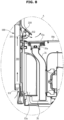
- FIG. 6 is a view illustrating a first damper 220 according to an embodiment of the disclosure.
- FIG. 6 is a view illustrating a part B of FIG. 3 in detail.
- the first damper 220 is provided to regulate the connection between the connection duct and the second circulation flow path 70.
- the first damper 220 is configured to open and close a connection flow path hole 81 of the top cover 80.
- the first damper 220 may include a second flow path opening and closing member configured to open and close the connection flow path hole 81, and a second motor configured to rotate the second flow path opening and closing member.
- the air flowing from the second damper 210 may be discharged to the outside through the first damper 220.
- the drying cycle may start.
- the first damper and the second damper may be allowed to opened or closed based the temperature and humidity of the inside and the outside of the chamber, and thus it is possible to efficiently dry objects to be dried as described below. A description thereof will be described in detail.
- FIG. 7 illustrates a control block diagram of the clothes care apparatus 1 according to an embodiment of the disclosure.
- the clothes care apparatus 1 includes a blower fan 90, the first damper 220, the second damper 210, the heat exchanger 30, the sensor portion 240, and a controller 200.
- the blower fan is provided as a configuration configured to generate an air flow.
- the blower fan 90 may include the first blower fan 72 corresponding to the first damper 220 and configured to generate the air flow from the chamber to the outside, and the second blower fan 32 corresponding to the second damper 210 and configured to generate the air flow from the outside to the heat exchanger 30.
- the first damper 220 may be provided as an upper damper provided in the upper portion of the clothes care apparatus, and the second damper 210 may be provided as a lower damper provided in the lower portion of the clothes care apparatus.
- the first damper 220 may correspond to the first blower fan 72. Particularly, as for controlling the flow of the outside air, the first damper 220 may be opened so as to induce the flow of the outside air by driving the first blower fan 72.
- the second damper 210 may correspond to the second blower fan 32.
- the second damper 210 may be opened to introduce the outside air, and when the second blower fan 32 is driven as described below, the second damper 210 may induce the outside air to the heat exchanger 30 and heat the outside air.
- the heat exchanger 30 is configured heat the air and supply the heated air to the chamber 11.
- the sensor portion 240 obtains a temperature and humidity of the inside of the clothes care apparatus 1.
- the sensor portion 240 is provided on the outside of the clothes care apparatus 1 to obtain a temperature and humidity of the outside of the clothes care apparatus 1.
- the controller 200 determines an external absolute humidity and an internal absolute humidity of the clothes care apparatus 1 based on the temperature and humidity obtained by the sensor portion 240.
- the controller 200 may perform the drying cycle using the inside air through the heat exchanger. Further, the controller 200 may use the outside air for drying objects to be dried by opening the damper when a temperature and humidity of the inside of the chamber meet predetermined conditions.
- the controller 200 may open at least one of the first damper 220 and the second damper 210 based on the external absolute humidity and the internal absolute humidity.
- the first blower fan 72 may be driven according to the opening of the first damper 220.
- the controller 200 may control the operation of the heat exchanger 30 based on the external absolute humidity and internal absolute humidity. Particularly, when the external absolute humidity is lower than the internal absolute humidity, the controller 200 directly dries the clothes placed in the clothes care apparatus by using the outside air. At this time, the controller 200 stops driving of the compressor 35.
- Absolute humidity may refer to the mass of water vapor contained per unit volume.
- the controller 200 may start the drying cycle by closing the first damper 220 and the second damper 210 and driving the second blower fan 32 and the heat exchanger 30.
- controller 200 may determine the drying efficiency to the power according to the performance of the drying cycle.
- the controller may determine the drying efficiency based on the humidity and temperature of the chamber. Particularly, the controller may determine that the drying efficiency is inappropriate when the temperature of the chamber exceeds 40°C and the humidity is less than 40%.
- the controller may determine that the chamber meets a predetermined condition.
- the predetermined condition may represent a condition that allows the clothes care apparatus to use the outside air to dry objects to be dried.
- the controller 200 opens at least one of the first damper 220 and the second damper and drives at least one of blower fans 72 and 32 based on the external absolute humidity and the internal absolute humidity, thereby introducing the outside air.
- the controller 200 stops driving of the compressor 35. Accordingly, it is possible to achieve the efficient power management.
- the controller 200 may start to control of opening the damper based on the humidity and temperature of the chamber.
- the controller 200 opens the first damper 220 and the second damper 210 and drives at least one of the first blower fan 72 and the second blower fan 32. Accordingly, air may flow from the second damper 210 to the first damper 220 through the chamber 11.
- the controller 200 may open the second damper 210 to introduce the outside air into the clothes care apparatus 1. In this case, the controller 200 may stop driving of the compressor 35 for the efficiency of power.
- the controller 200 may drive the first blower fan 72 to directly introduce the outside air into the chamber 11 without passing through the heat exchanger 30.
- the controller 200 may close the first damper 220 and drive the second blower fan 32 and the compressor 35
- the controller 200 may introduce the outside air and heat the air by the heat exchanger 30 and then supply the heated air to the chamber.
- the controller may generate the air flow in which air sequentially flows in the second damper 210, the heat exchanger 30, the chamber 11 and the first damper 220.
- the controller 200 may allow the heat exchanger 30 to consume predetermined power consumption.
- the controller 200 may drive the compressor 35 included in the heat exchanger 30 at a predetermined frequency (such as a minimum frequency).
- the minimum frequency may represent a frequency that is applied to consume the power less than the power that is consumed by the compressor in the drying cycle before opening the damper.
- the minimum frequency may represent a frequency that is applied when driving the compressor 35 included in the heat exchanger 30 with minimum power.
- the minimum frequency may represent a low frequency capable of generating hot or cold air by driving the compressor.
- the minimum frequency may represent the smallest frequency among the range of frequencies for driving the compressor 35.
- the controller 200 may close the first damper 220 and the second damper 210, and drive the blower fans 32 and 72 and the heat exchanger 30, thereby drying objects to be dried in the chamber.
- the predetermined value of the external humidity described above may be set to be 85%.
- the sensor portion 240 may be provided inside the clothes care apparatus 1.
- the controller 200 may determine an external absolute humidity.
- the absolute humidity of the inside of the clothes care apparatus 1 may be the same as the absolute humidity of the outside of the clothes care apparatus 1.
- the controller 200 may determine the absolute humidity of the inside of the clothes care apparatus 1 based on the information obtained by the sensor portion 240 provided therein. For the above-described operation, the controller may open the first damper and the second damper before starting the drying cycle.
- the controller 200 may determine the absolute humidity of the inside of the clothes care apparatus 1 at the start timing of the drying cycle as the absolute humidity of the outside of the clothes care apparatus 1.
- the sensor portion 240 may be provided on the outside of the clothes care apparatus 1 in the form of an external sensor as well as being provided inside the clothes care apparatus 1.
- the controller 200 may determine the internal absolute humidity based on the temperature and humidity obtained by an internal sensor, and determine the external absolute humidity based on the temperature and humidity obtained by an external sensor.
- the controller 200 may include a memory (not shown) configured to store an algorithm for controlling an operation of components in the clothes care apparatus 1 or configured to store data about a program implementing the algorithm, and a processor (not shown) performing the above mentioned operation using the data stored in the memory.
- the memory and the processor may be implemented in separate chips, or a single chip.
- At least one component may be added or deleted in accordance with the performance of the components of the clothes care apparatus 1 shown in FIG. 7 .
- the location of components may be changed in accordance with the performance or structure of the system.
- FIG. 8 is a view illustrating a flow of outside air according to an embodiment of the disclosure.
- the controller 200 of the clothes care apparatus 1 may drive the first blower fan so as to directly introduce the outside air into the chamber.
- the controller performs the following operation.
- the air introduced as mentioned above is directly introduced into the chamber 11 without passing through the heat exchanger 30.
- at least one of the blower fans 72 and 32 is operated and the first damper 220 is opened.
- the first damper 220 and the second damper 210 may be opened to allow the outside air to flow in.
- the outside air may be directly discharged to the outside through the chamber 11 without passing through the heat exchanger 30.
- the controller 200 uses the outside air for drying an object to be dried as it is.
- FIGS. 9 to 11 are views illustrating an operation of the damper, the fan and the heat exchanger according to an embodiment of the disclosure.
- FIGS. 9A and 9B are schematic views illustrating an operation of the clothing care apparatus when the external absolute humidity is higher than the internal absolute humidity.
- FIG. 9A is a view illustrating the clothes care apparatus provided with the first blower fan 72 and the second blower fan 32.
- the controller may supply the outside air to the chamber through the heat exchanger.
- the controller may control the second damper 210, the second blower fan 32 and the heat exchanger 30 based on the humidity of the inside of the chamber 11.
- the controller 200 may open the second damper 210 and drive the second blower fan 32 to introduce the outside air. Meanwhile, the controller 200 may allow the first blower fan 72 to be driven or not. When the first blower fan is driven, the air may be discharged more quickly from the chamber to the outside.
- the controller 200 may introduce the outside air and heat the outside air in the heat exchanger 30.
- the heat exchanger 30 may heat the outside air and discharge air having a low humidity into the chamber 11.
- the controller 200 may drive the second blower fan 32 to generate an air flow in which air flows from the second damper 210 to the chamber 11 through the heat exchanger 30.
- the controller 200 may drive the compressor 35 at the minimum frequency.
- the controller 200 may drive the compressor 35 of the heat exchanger 30 by fixing the driving frequency to the minimum frequency.
- the above operation may be implemented by using a single blower fan.
- the controller may open the first damper 220 and the second damper 210 and drive the second blower fan 32.
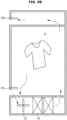
- FIGS. 10A and 10B are schematic views illustrating an operation of the clothing care apparatus when the external absolute humidity is less than the internal absolute humidity.
- FIG. 10A is a view illustrating the clothes care apparatus provided with the first blower fan and the second blower fan.
- the clothes care apparatus 1 directly uses outside air to dry an object to be dried in the chamber 11.
- the controller 200 opens the first damper 220 and the second damper 210 and may start to drive the first blower fan 72. In addition, the controller 200 stops driving of the compressor 35.
- the controller 200 opens the first damper 220 and may start to drive the first blower fan 72 so as to introduce outside air. Unlike FIG. 9 , the outside air is not introduced into the heat exchanger but is directly introduced into the chamber 11. Based on the above mentioned operation, the controller 200 generates an air flow, in which air flows from the second damper 210 to the first damper 220 through the chamber 11.
- the controller directly uses the outside air for drying objects to be dried.
- the controller 200 stops driving of the compressor 35. Because it is possible to efficiently dry objects to be dried only with the outside air itself, the controller 200 stops driving of the compressor 35 to prevent power loss.
- the above operation may be implemented by using a single blower fan.
- the controller may open the first damper 220 and the second damper 210 and drive the second blower fan 32. In this case, outside air may be introduced into the heat exchanger 30 through the second damper.
- the controller stops the operation of the compressor 35 when the external absolute humidity is less than the internal absolute humidity.
- the outside air may be introduced into the heat exchanger 30 but be discharged into the chamber 11 without being heated.
- the controller may introduce the outside air to the inside of the clothes care apparatus and discharge the air to the outside of the clothes care apparatus.
- FIG. 11 is a view illustrating an operation when the external humidity is higher than or equal to a predetermined value.
- the controller When the outside air is introduced in a state in which the external humidity is higher than or equal to the predetermined value, efficiency may be lowered. Therefore, the controller may be operated as described below without opening the damper.
- the controller 200 may drive the second blower fan 32 to supply the inside air to the chamber 11 through the heat exchanger 30 when the external humidity is higher than or equal to the predetermined value.
- the predetermined value may be set to be 85%.
- the controller may maintain a closed state of the first damper 220 and the second damper 210.
- the controller may raise the temperature of the inside air through the heat exchanger 30 and then provide the heated air to the chamber.
- the controller may introduce the inside air to the heat exchanger 30 by using the second blower fan 32 and heat the inside air and then discharge the heated air to the chamber 11.
- FIGS. 9 to 11 illustrate that the operation of the clothes care apparatus when the temperature and humidity of the chamber meet predetermined conditions after the drying cycle starts.
- the above operations illustrate an operation that is performed when the temperature and humidity of the chamber of the clothes care apparatus meet the predetermined condition during the drying cycle that is performed by using the inside air by using the heat exchanger.
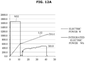
- FIGS. 12A and 12B are views illustrating an operation for determining a predetermined reference according to an embodiment of the disclosure; and FIGS. 12A and 12B are graphs illustrating changes in consumption input and an internal humidity and temperature in each operation during the drying cycle of the clothes care apparatus.
- FIGS. 12A and 12B it is shown that a slope of the change in humidity of the clothes care apparatus is rapidly lowered in an operation in which a consumption input of the heat exchanger 30 is the highest of 501W.
- this section corresponds to an inefficiency section in the drying cycle with respect to the consumption input.
- the temperature of the chamber of the clothes care apparatus may exceed the reference temperature, and the humidity of the chamber may drop below the reference humidity.
- the reference temperature may be determined to be 40°C and the reference humidity may be determined to be 40%.
- the controller 200 may dry an object to be dried using the outside air instead of driving the heat exchanger 30.
- the controller 200 may stop driving of the compressor 35 and start to drive the first damper 220 and the second damper 210 and drive the first blower fan 72 when the predetermined condition is satisfied.
- the controller 200 may determine the predetermined reference based on the change in the internal humidity of the clothes care apparatus N12 and the power consumption of the clothes care apparatus M12, and L12.
- the controller 200 may determine a reference timing based on a ratio of the change in the internal humidity and power consumption.
- the controller may determine whether the condition of the clothes care apparatus meet the predetermined condition or not based on the reference temperature and the reference humidity.
- the controller 200 may determine that the condition of the chamber of the clothes care apparatus meets the predetermined condition at 40 minutes.
- the reference timing may be determined in real time by the controller 200 or may be determined in advance.
- the controller 200 may determine whether to use the outside air for drying based on the external absolute humidity and the internal absolute humidity at the reference timing
- the controller 200 may open the second damper 210, and drive the second blower fan 32 and the heat exchanger 30.
- the controller 200 may start to open the first damper 220 and drive the first blower fan 72 based on the external absolute humidity and the internal absolute humidity at the reference timing determined based on the above-described method.
- the controller 200 may start to open the first damper 220 and the second damper 210, and drive the first blower fan 72, and stop driving the compressor 35. In addition, in this case, the controller 200 may stop driving of the second blower fan 32 and the compressor 35.
- the outside air may be directly introduced into the chamber without passing through the heat exchanger 30 and used for drying an object to be dried.
- the controller 200 may drive the second blower fan to introduce the outside air into the heat exchanger 30.
- the controller 200 may dry the object to be dried in the chamber by opening the second damper 210, and driving the second blower fan 32 and the heat exchanger 30.
- the controller 200 may allow the heat exchanger 30 to consume the minimum power, and allow the compressor 35 to operate at the minimum frequency.
- FIGS. 12A and 12B are only an embodiment for describing the operation of the disclosure, and the operation of determining the reference timing is not limited thereto.
- FIGS. 13 and 14 illustrates flowcharts according to an embodiment of the disclosure.
- FIG. 13 illustrates a view illustrating the operation of the clothes care apparatus when an external sensor and an internal sensor are provided.
- the clothes care apparatus starts the drying cycle (step 1001), and the controller determines whether the predetermined condition is satisfied or not (step 1002), which is whether or not the temperature of the chamber is higher than or equal to the reference temperature and the humidity of the chamber is less than the reference humidity.
- step 1003 the controller uses the outside air for drying the object to be dried, by opening the damper.
- the controller opens the first and second dampers (step 1004).
- the controller stops driving of the compressor (step 1007) and dries the object to be dried by using the outside air (step 1005).
- the controller may dry the object to be dried by driving the compressor at the minimum frequency (step 1006).
- FIG. 14 is a view illustrating the operation of the clothes care apparatus when the internal sensor is provided.
- the clothes care apparatus may open the damper (step 1011) before the drying cycle and determine the external absolute humidity based on the sensor provided therein (step 1012).
- the clothes care apparatus may close the damper (step 1013) and start the drying cycle (step 1014).
- the clothes care apparatus may start the drying cycle (step 1014), and the controller may determine whether the predetermined condition is satisfied or not (step 1015), which is whether or not the temperature of the chamber is higher than or equal to the reference temperature and the humidity of the chamber is less than the reference humidity.
- the controller uses the outside air for drying the object to be dried, by opening the damper.
- the controller opens the first and second dampers (step 1017).
- the controller stops driving of the compressor (step 1020) and dries the object to be dried by using the outside air (step 1018).
- the controller may dry the object to be dried by driving the compressor at the minimum frequency (step 1019).
- the blower fan included in the clothes care apparatus may be operated.
- the blower fan may include at least one of the first blower fan configured to generate the air flow, in which the air flows from the chamber to the outside, and the second blower fan configured to generate the air flow, in which the air flows from the outside to the heat exchanger. That is, the clothes care apparatus may be implemented with a single blower fan or a plurality of blower fans.
- the blower fan is operated to introduce the outside air into the chamber when the external humidity is less than the internal humidity. Subsequently, the blower fan may be operated to discharge the air of the chamber to the outside. Meanwhile, even in this case, the outside air may be introduced into the chamber through the heat exchanger based on the operation of the blower fan.
- the blower fan may be operated to introduce the outside air into the heat exchanger when the external humidity is greater than the internal humidity.
- the blower fan may be operated to discharge air from the chamber to the outside.
- the blower fan may be operated to circulate the inside air without introducing the outside air.
- the clothes care apparatus and the control method thereof may efficiently manage power by drying an object to be dried using the outside air and controlling a heat exchanger.
- the disclosed embodiments may be embodied in the form of a recording medium storing instructions executable by a computer.
- the instructions may be stored in the form of program code and, when executed by a processor, may generate a program module to perform the operations of the disclosed embodiments.
- the recording medium may be embodied as a computer-readable recording medium.
- the computer-readable recording medium includes all kinds of recording media in which instructions which can be decoded by a computer are stored.
- ROM Read Only Memory
- RAM Random Access Memory
- magnetic tape a magnetic tape
- magnetic disk a magnetic disk
- flash memory a flash memory
- optical data storage device an optical data storage device
Landscapes
- Engineering & Computer Science (AREA)
- Textile Engineering (AREA)
- Control Of Washing Machine And Dryer (AREA)
- Detail Structures Of Washing Machines And Dryers (AREA)
Description
- The invention relates to a clothes care apparatus capable of performing a drying cycle of clothes, removing wrinkles from the clothes and capable of removing dust attached to clothes or smell of the clothes.
- A clothes care apparatus is a type of device performing clothes care such as drying wet clothes, removing dust attached to the clothes or eliminating remaining odors in the clothes and removing wrinkles from the clothes.
- In addition, the clothes care apparatus has a vapor compression heat pump system and is capable of drying object through the air circulation.
- Meanwhile, in the drying cycle of the conventional clothes care apparatus, the operation of the heat pump is performed until the end of drying is identified. This method may be effective when an object to be dried has a large amount of moisture. However, at a time in which the amount of moisture is reduced due to the proceeding of the drying cycle, this method may have the poor drying efficiency with respect to the power consumption.
- Therefore, there is a need for a technique for performing a smooth drying cycle with efficient power consumption.
- A drying apparatus and method for improving drying efficiency is described in
KR2019-0000146A - Therefore, it is an aspect of the disclosure to provide a clothes care apparatus capable of efficiently managing power by drying an object to be dried using the outside air and controlling a heat exchanger, and a control method thereof.
- Additional aspects of the disclosure will be set forth in part in the description which follows and, in part, will be obvious from the description, or may be learned by practice of the disclosure.
- In accordance with an aspect of the disclosure, there is provided a clothes care apparatus according to
claim 1. - When the drying cycle starts, the controller may close the first damper and the second damper, and perform driving of the blower fan and the heat exchanger, and when the internal humidity of the chamber is less than a reference humidity and the internal temperature of the chamber is higher than or equal to a reference temperature, the controller may determine that the predetermined condition is satisfied.
- The blower fan may include a first blower fan configured to generate the air flow from the chamber to the outside, and the controller may directly introduce the outside air to the chamber by driving the first blower fan.
- When the external humidity exceeds the internal humidity, the controller may drive the compressor, open the first damper and the second damper, and drive the blower fan so as to generate the air flow in which air flows from the second damper to the chamber through the heat exchanger.
- The blower fan may include a second blower fan configured to generate the air flow from the outside to the heat exchanger.
- The controller may allow the compressor to drive at a predetermined frequency, such as a minimum frequency.
- The minimum frequency may correspond to a frequency that is applied to consume power less than power that is consumed by the compressor before the predetermined condition is satisfied.
- When the external humidity exceeds a predetermined value, the controller may close the first damper and the second damper and drive the blower fan and the compressor.
- The sensor portion may be provided inside the chamber, and the controller may open the first damper and the second damper at a start timing of the drying cycle and determine the external absolute humidity based on a temperature and humidity of the inside of the clothe care apparatus.
- The sensor portion may include an internal sensor provided in the inside of the clothes care apparatus and an external sensor provided on the outside of the clothes care apparatus, and the controller may determine the internal absolute humidity based on a temperature and humidity obtained by the internal sensor, and the controller may determine the external absolute humidity based on a temperature and humidity obtained by the external sensor.
- The internal humidity may correspond to the absolute humidity of the inside of the chamber, and the external humidity may correspond to the absolute humidity of the outside of the clothes care apparatus.
- In accordance with another aspect of the disclosure, there is provided a control method of a clothes care apparatus according to claim 12.
- Performing a drying cycle by using inside air through a heat exchanger may include closing the first damper and the second damper, and performing driving of the blower fan and the heat exchanger, and when the internal humidity of the chamber is less than a reference humidity and the internal temperature of the chamber is higher than or equal to a reference temperature, determining that the predetermined condition is satisfied.
- The blower fan may include a first blower fan configured to generate the air flow from the chamber to the outside, and controlling at least one blower fan may include directly introducing the outside air to the chamber by driving the first blower fan.
- Allowing a first damper and a second damper to be opened or closed and controlling driving of the heat exchanger and at least one blower fan by comparing the internal humidity with the external humidity may include, when the external humidity exceeds the internal humidity, driving the compressor, opening the first damper and the second damper, and driving the blower fan, thereby generating an air flow in which air flows from the second damper to the chamber through the heat exchanger.
- The blower fan may include a second blower fan configured to generate the air flow from the outside to the heat exchanger.
- Controlling the compressor may include allowing the compressor to drive at a predetermined frequency such as a minimum frequency.
- The minimum frequency may correspond to a frequency that is applied to consume the power less than the power that is consumed by the compressor before the predetermined condition is satisfied.
- Allowing a first damper and a second damper to be opened or closed and controlling driving of the heat exchanger and at least one blower fan by comparing the internal humidity with the external humidity may include, when the external humidity exceeds a predetermined value, closing the first damper and the second damper and driving the blower fan and the compressor.
- Obtaining a temperature and humidity of the inside and the outside of a chamber may include opening the first damper and the second damper at a start timing of the drying cycle, and determining the external absolute humidity based on a temperature and humidity of the inside of the clothe care apparatus.
- Obtaining a temperature and humidity of the inside and the outside of a chamber may include determining the internal absolute humidity based on a temperature and humidity obtained by an internal sensor, and determining the external absolute humidity based on a temperature and humidity obtained by an external sensor.
- The internal humidity may correspond to the absolute humidity of the inside of the chamber, and the external humidity may correspond to the absolute humidity of the outside of the clothes care apparatus.
- Embodiments of the invention are set out in the dependent claims. In the following, embodiments that do not fall within the scope of the claims relate to exemplary embodiments of the disclosure that are not covered by the claimed invention.
- Before undertaking the DETAILED DESCRIPTION below, it may be advantageous to set forth definitions of certain words and phrases used throughout this patent document: the terms "include" and "comprise," as well as derivatives thereof, mean inclusion without limitation; the term "or," is inclusive, meaning and/or; the phrases "associated with" and "associated therewith," as well as derivatives thereof, may mean to include, be included within, interconnect with, contain, be contained within, connect to or with, couple to or with, be communicable with, cooperate with, interleave, juxtapose, be proximate to, be bound to or with, have, have a property of, or the like; and the term "controller" means any device, system or part thereof that controls at least one operation, such a device may be implemented in hardware, firmware or software, or some combination of at least two of the same. It should be noted that the functionality associated with any particular controller may be centralized or distributed, whether locally or remotely.
- Moreover, various functions described below can be implemented or supported by one or more computer programs, each of which is formed from computer readable program code and embodied in a computer readable medium. The terms "application" and "program" refer to one or more computer programs, software components, sets of instructions, procedures, functions, objects, classes, instances, related data, or a portion thereof adapted for implementation in a suitable computer readable program code. The phrase "computer readable program code" includes any type of computer code, including source code, object code, and executable code. The phrase "computer readable medium" includes any type of medium capable of being accessed by a computer, such as read only memory (ROM), random access memory (RAM), a hard disk drive, a compact disc (CD), a digital video disc (DVD), or any other type of memory. A "non-transitory" computer readable medium excludes wired, wireless, optical, or other communication links that transport transitory electrical or other signals. A non-transitory computer readable medium includes media where data can be permanently stored and media where data can be stored and later overwritten, such as a rewritable optical disc or an erasable memory device.
- Definitions for certain words and phrases are provided throughout this patent document, those of ordinary skill in the art should understand that in many, if not most instances, such definitions apply to prior, as well as future uses of such defined words and phrases.
- These and/or other aspects of the disclosure will become apparent and more readily appreciated from the following description of embodiments, taken in conjunction with the accompanying drawings of which:
-
FIG. 1 illustrates a view of a clothes care apparatus according to an embodiment of the disclosure; -
FIG. 2 is a view illustrating a state in which a door of the clothes care apparatus according to an embodiment of the disclosure is opened; -
FIG. 3 illustrates a side cross-sectional view of the clothes care apparatus according to an embodiment of the disclosure; -
FIG. 4 is an exploded view illustrating the clothes care apparatus according to an embodiment of the disclosure; -
FIG. 5 is a view illustrating a lower damper according to an embodiment of the disclosure; -
FIG. 6 is a view illustrating an upper damper according to an embodiment of the disclosure; -
FIG. 7 illustrates a control block diagram of the clothes care apparatus according to an embodiment of the disclosure; -
FIG. 8 is a view illustrating a flow of outside air according to an embodiment of the disclosure; -
FIG. 9 is a view illustrating an operation of a damper, a fan and a heat exchanger according to an embodiment of the disclosure; -
FIG. 10 is a view illustrating an operation of the damper, the fan and the heat exchanger according to an embodiment of the disclosure; -
FIG. 11 is a view illustrating an operation of the damper, the fan and the heat exchanger according to an embodiment of the disclosure; -
FIG. 12A is a view illustrating an operation for determining a reference time according to an embodiment of the disclosure; -
FIG. 12B is a view illustrating the operation for determining the reference time according to an embodiment of the disclosure; -
FIG. 13 illustrates a flowchart according to an embodiment of the disclosure; and -
FIG. 14 illustrates a flowchart according to an embodiment of the disclosure. -
FIGS. 1 through 14 , discussed below, and the various embodiments used to describe the present disclosure are by way of illustration only and should not be construed in any way to limit the scope of the disclosure, which is defined by the claims. Those skilled in the art will understand that the principles of the present disclosure may be implemented in any suitably arranged system or device. - In the following description, like reference numerals refer to like elements throughout the specification. Well-known functions or constructions are not described in detail since they would obscure the one or more exemplar embodiments with unnecessary detail.
- Terms such as "unit", "portion", "block", "member" and "module" may be embodied as hardware or software. In addition, "unit", "portion", "block", "member" and "module" may indicate a unit for processing at least one function or operation. In addition, terms such as "unit", "portion", "block", "member" and "module" may refer to at least one process processed by at least one software or process stored in at least one hardware, circuit, and a memory. According to embodiments, "unit", "portion", "block", "member" and "module" may include at least one component.
- It will be understood that when an element is referred to as being "connected" another element, it can be directly or indirectly connected to the other element, wherein the indirect connection includes "connection via a wireless communication network". Also, when a part "includes" or "comprises" an element, unless there is a particular description contrary thereto, the part may further include other elements, not excluding the other elements.
- It will be understood that, although the terms first, second, third, etc., may be used herein to describe various elements, but is should not be limited by these terms. These terms are only used to distinguish one element from another element. As used herein, the singular forms "a," "an" and "the" are intended to include the plural forms as well, unless the context clearly indicates otherwise.
- An identification code is used for the convenience of the description but is not intended to illustrate the order of each step. Each step may be implemented in the order different from the illustrated order unless the context clearly indicates otherwise.
- The disclosure will be described more fully hereinafter with reference to the accompanying drawings.
-
FIG. 1 illustrates a view of a clothes care apparatus according to an embodiment of the disclosure,FIG. 2 is a view illustrating a state in which a door of the clothes care apparatus according to an embodiment of the disclosure is opened,FIG. 3 illustrates a side cross-sectional view of the clothes care apparatus according to an embodiment of the disclosure, andFIG. 4 is an exploded view illustrating the clothes care apparatus according to an embodiment of the disclosure. - As illustrated in
FIGS. 1 to 4 , aclothes care apparatus 1 includes abody 10 forming an external appearance, adoor 20 rotatably coupled tobody 10, achamber 11 provided inside thebody 10 to allow clothes to be placed and to be managed, aclothes support member 50 provided inside thechamber 11 to allow clothes to be hung thereon, and amachine room 13 provided with aheat exchanger 30 configured to dehumidify or heat air in thechamber 11. - The
body 10 has thechamber 11 formed therein, and may have a hexahedron shape having an open one surface. Anopening 10a may be formed on the front surface of thebody 10. Thedoor 20 is rotatably coupled to theopening 10a of thebody 10 to open and close thechamber 11. Although not shown, thedoor 20 may be installed through a connecting member such as a hinge and a link. - The
chamber 11 forms a space in which clothes are accommodated. Thechamber 11 may be formed by including anupper surface 10b, alower surface 10c, aleft side surface 10d, aright side surface 10e, and arear surface 10f provided inside thebody 10. The front surface of thechamber 11 is formed to be open. Therefore, the opening of thechamber 11 may also be opened and closed by thedoor 20 configured to open and close theopening 10a of thebody 10. - A
discharge bracket 16 installed in a position corresponding to adischarge flow path 120 of thedoor 20 described later may be provided on an upper end of theopening 10a of thebody 10. Thedischarge bracket 16 may include a plurality ofslits 16a arranged in accordance with thedischarge flow path 120 of thedoor 20. - The clothes support
member 50 configured to allow clothes to be hung and to be supported, is provided in thechamber 11. The clothes supportmember 50 may be installed on theupper surface 10b of thechamber 11. The clothes supportmember 50 may be removably installed in thechamber 11. One or more clothes supportmember 50 may be provided. The clothes supportmember 50 may be formed in a clothes hanger shape to allow clothes to be hung. - The clothes support
member 50 is configured to allow air to flow therein. Dust or foreign substances on the clothes may be removed by the air supplied into the clothes supportmember 50. The clothes supportmember 50 may be provided with anair hole 51 for supplying air to the clothes. According to an embodiment, it is assumed that the air hole is arranged on an upper end of the clothes supportmember 50, and the air discharged through the air hole is supplied to the inside and the outside of the clothes, but is not limited thereto. For example, the air hole may be formed in various sizes at various positions to inject air into the clothes in various directions. - The
chamber 11 may include afirst airflow inlet 11a, a second airflow inlet, afirst airflow outlet 11b, asecond airflow outlet 12b and a steam outlet. Thefirst airflow inlet 11a and thefirst airflow outlet 11b may be formed on thelower surface 10c of thechamber 11. Thefirst airflow inlet 11a may be arranged in a front portion of thelower surface 10c of thechamber 11. Thefirst airflow outlet 11b may be arranged in a rear portion of thelower surface 10c of thechamber 11. - The
first airflow inlet 11a and thefirst airflow outlet 11b may be arranged adjacent to each other. - The steam outlet may be arranged in a lower portion of the
rear surface 10f of thechamber 11. The steam outlet may be arranged in an upper side of thefirst airflow outlet 11b. - The second airflow inlet may be formed at an upper portion of the
rear surface 10f of thechamber 11. Thesecond airflow outlet 12b may be formed at a substantially central portion of theupper surface 10b of thechamber 11. The second airflow inlet and thesecond airflow outlet 12b may be arranged adjacent to each other. - The
second airflow outlet 12b of thechamber 11 may be connected to the clothes supportmember 50. Air discharged through thesecond airflow outlet 12b may be delivered to the clothes supportmember 50 through theair hole 51 and then delivered to the clothes hung on the clothes supportmember 50. - In the lower portion of the
body 10, awater drain tank 15a and awater supply tank 15b removably installed to thebody 10 may be provided. Thewater drain tank 15a and thewater supply tank 15b may be arranged under thechamber 11. Thewater drain tank 15a may be configured to easily treat condensed water. Thewater supply tank 15b may store water needed for asteam generation device 40 to generate steam described later. That is, water of thewater supply tank 15b is supplied to thesteam generation device 40 and then used to generate steam. Thewater supply tank 15b may be removably mounted to thebody 10 so as to easily supplement water. - The
water drain tank 15a and thewater supply tank 15b may be provided in front of themachine room 13. Themachine room 13 is provided in the lower portion of thebody 10. Themachine room 13 is provided under thechamber 11. Themachine room 13 may include theheat exchanger 30 configured to dehumidify and heat air in thechamber 11 as needed. - A
second blower fan 32, theheat exchanger 30, and thesteam generation device 40 may be arranged inside themachine room 13. - The
heat exchanger 30 is installed to supply hot air into thechamber 11. Theheat exchanger 30 includes anevaporator 33, acompressor 35 and acondenser 34 through which a refrigerant circulates, and theheat exchanger 30 is configured to dehumidify and heat the air. - As the refrigerant evaporates in the
evaporator 33 of theheat exchanger 30, the refrigerant absorbs latent heat of the ambient air so as to condense and remove moisture in the air. In addition, when the refrigerant is passed through thecompressor 35 and then condensed in thecondenser 34, the latent heat is released toward the ambient air to heat the ambient air. - That is, the
evaporator 33 and thecondenser 34 function as heat exchangers, and the air, which flows into themachine room 13 by thesecond blower fan 32, is dehumidified and heated while passing through theevaporator 33 and thecondenser 34 sequentially. - The
heat exchanger 30 installed in themachine room 13 may include afirst duct 31 configured to connect theevaporator 33, thecondenser 34 and thesecond blower fan 32, and thefirst duct 31 may be connected to thechamber 11, thereby forming a firstcirculation flow path 39 circulating between thechamber 11 and thefirst duct 31. - The
first duct 31 may be connected to thefirst airflow inlet 11a and thefirst airflow outlet 11b of thechamber 11. One end of thefirst duct 31 may be connected to thefirst airflow inlet 11a of thechamber 11, and the other end of thefirst duct 31 may be connected to thefirst airflow outlet 11b of thechamber 11. Afirst duct inlet 31a of thefirst duct 31 may be connected to thefirst airflow inlet 11a and afirst duct outlet 31b may be connected to thefirst airflow outlet 11b. - Air in the
chamber 11 may flow into thefirst duct 31 through thefirst airflow inlet 11a. The flowing air may be dehumidified and then discharged to thechamber 11 again, through thefirst airflow outlet 11b. According to an embodiment, it is assumed that the first airflow inlet is arranged in the front portion of the chamber and the first airflow outlet is arranged in the rear portion of the chamber, but is not limited thereto. Therefore, a location of the airflow inlet and airflow outlet may vary, as needed. - The
first duct 31 is configured to dehumidify the air flowing through thefirst airflow inlet 11a, and to discharge the dehumidified air to thefirst airflow outlet 11b. Thesecond blower fan 32 is installed on thefirst duct 31 to suck the air of thechamber 11 into thefirst duct 31. - The
machine room 13 may further include thesteam generation device 40 configured to generate steam by receiving water from thewater supply tank 15b. Thesteam generation device 40 may be arranged in themachine room 13. Thesteam generation device 40 may include asteam generator 41 connected to thewater supply tank 15b to receive the water so as to generate steam, and a steam supply pipe configured to guide the generated steam to asteam injector 42. Thesteam injector 42 may be arranged in a lower portion of the rear surface of thechamber 11. - A heater (not shown) may be installed inside the
steam generator 41 to heat water. - The
chamber 11 may include afirst blower fan 72 configured to move the air in thechamber 11. - The
chamber 11 may include asecond duct 71, and thefirst blower fan 72 may be installed in thesecond duct 71. Thesecond duct 71 may communicates with thechamber 11, and accordingly, a secondcirculation flow path 70 configure to allow air to circulate between thechamber 11 and thesecond duct 71 may be formed. Thefirst blower fan 72 may be arranged on the secondcirculation flow path 70. - The
second duct 71 may be formed behind the second airflow inlet of thechamber 11. Thesecond duct 71 may be provided at the upper rear of thechamber 11, and may include afilter member 60 therein. Thesecond duct 71 may be coupled to atop cover 80 arranged above thechamber 11. Thesecond duct 71 may be coupled to thetop cover 80 and thefirst blower fan 72 may be installed therein. Thefirst blower fan 72 may be arranged at the upper rear of thechamber 11. Thefirst blower fan 72 may include ablower motor 72a configured to generate a rotational force, and at least onefan 72b configured to rotate by the blower motor. Thefan 72b may be accommodated by afan case 72c. Thefan case 72c may be coupled to aduct bracket 74 provided on theupper surface 10b of thechamber 11. At least oneduct hole 74a is formed in theduct bracket 74, and thefirst blower fan 72 is coupled to the at least oneduct hole 74a to supply air of thesecond duct 71 to thesecond airflow outlet 12b of thesecond duct 71. - The
second duct 71 may be connected to the second airflow inlet and thesecond airflow outlet 12b of thechamber 11. One end of thesecond duct 71 may be connected to the second airflow inlet of thechamber 11, and the other end of thesecond duct 71 may be connected to thesecond airflow outlet 12b. A second duct inlet of thesecond duct 71 may be connected to the second airflow inlet and asecond duct outlet 71b may be connected to thesecond airflow outlet 12b. - The
second airflow outlet 12b of thechamber 11 may be formed on a position corresponding to thesecond duct outlet 71b of thesecond duct 71. - The
second duct outlet 71b of thesecond duct 71 may be connected to thesecond airflow outlet 12b of thechamber 11, and thesecond airflow outlet 12b of thechamber 11 may be connected to the clothes supportmember 50. Therefore, the air of thesecond duct 71 may be delivered to the clothes supportmember 50. - The
first blower fan 72 arranged in thesecond duct 71 sucks air in thechamber 11 through the second airflow inlet and discharges the air to thesecond duct outlet 71b and thesecond airflow outlet 12b. - The
filter member 60 is installed in the second airflow inlet of thechamber 11. The second airflow inlet is formed on therear surface 10f of thechamber 11. A filter member mounting portion in which thefilter member 60 installed is formed on therear surface 10f of thechamber 11. The second airflow inlet may be formed at a position corresponding to the filter member mounting portion. - When air of the
chamber 11 flows into thesecond duct 71, the air may be filtered by thefilter member 60 of the second airflow inlet. Dust and odor in the air flowing into thesecond duct 71 may be filtered out by thefilter member 60. The air filtered by thefilter member 60 may be discharged to thesecond duct outlet 71b and the clothes supportmember 50 by thefirst blower fan 72. - The
filter member 60 may include a dust collecting filter (not shown) for removing dust or a means for deodorization. - The
chamber 11 starts the clothes care when the clothes are hung on the clothes supportmember 50 and thedoor 20 is closed. In this case, in thechamber 11, air may be circulated along the firstcirculation flow path 39 and the secondcirculation flow path 70. - The clothes care
apparatus 1 includes adehumidification flow path 100 provided in thedoor 20 so as to connect thechamber 11 to the outside upon the dehumidification of the indoor. Thedehumidification flow path 100 may be provided on thedoor 20. Thedehumidification flow path 100 may be provided in plural. - Further, sensor portions 240-1 and 240-2 may be provided inside or outside the clothes care apparatus. The sensor portions 240-1 and 240-2 may be provided as sensors configured to measure a temperature and humidity. The sensor portions 240-1 and 240-2 may be provided inside the clothes care apparatus, and alternatively, may be provided inside and outside of the clothes care apparatus according to embodiments.
-
FIG. 5 is a view illustrating asecond damper 210 according to an embodiment of the disclosure. -
FIG. 5 is a view illustrating a part A ofFIG. 3 in detail. - The
dehumidification flow path 100 may be provided in a first door frame. Aninlet flow path 110 may be provided in the first door frame. - In the
inlet flow path 110, air flowing through afirst inlet 111 flows and is discharged to thechamber 11 through afirst outlet 112. - The
inlet flow path 110 may include an inletflow path duct 130 configured to guide air flowing through thefirst inlet 111 to flow. Thefirst outlet 112 may be formed in the inletflow path duct 130. - The
inlet flow path 110 may include thesecond damper 210 configured to open and close thefirst outlet 112. Thesecond damper 210 may be provided inside the inletflow path duct 130. Thesecond damper 210 may include a first flow path opening and closingmember 211 configured to open and close thefirst outlet 112, and a first motor 212 configured to rotate the first flow path opening and closingmember 211. - The outside air may flow into the clothes care apparatus from the
second damper 210. The outside air may be heated in thesecond damper 210 by the heat exchanger. In addition, the outside air may flow directly into the chamber from thesecond damper 210. -
FIG. 6 is a view illustrating afirst damper 220 according to an embodiment of the disclosure. -
FIG. 6 is a view illustrating a part B ofFIG. 3 in detail. - Referring to
FIG. 6 , in aconnection duct 91, thefirst damper 220 is provided to regulate the connection between the connection duct and the secondcirculation flow path 70. Thefirst damper 220 is configured to open and close a connection flow path hole 81 of thetop cover 80. Thefirst damper 220 may include a second flow path opening and closing member configured to open and close the connectionflow path hole 81, and a second motor configured to rotate the second flow path opening and closing member. - The air flowing from the
second damper 210 may be discharged to the outside through thefirst damper 220. - Meanwhile, referring to
FIGS. 5 and6 , in a state in which the first damper and the second damper are closed, the drying cycle may start. The first damper and the second damper may be allowed to opened or closed based the temperature and humidity of the inside and the outside of the chamber, and thus it is possible to efficiently dry objects to be dried as described below. A description thereof will be described in detail. -
FIG. 7 illustrates a control block diagram of the clothes careapparatus 1 according to an embodiment of the disclosure. - Referring to
FIG. 7 , the clothes careapparatus 1 includes ablower fan 90, thefirst damper 220, thesecond damper 210, theheat exchanger 30, thesensor portion 240, and acontroller 200. - The blower fan is provided as a configuration configured to generate an air flow. The
blower fan 90 may include thefirst blower fan 72 corresponding to thefirst damper 220 and configured to generate the air flow from the chamber to the outside, and thesecond blower fan 32 corresponding to thesecond damper 210 and configured to generate the air flow from the outside to theheat exchanger 30. - The
first damper 220 may be provided as an upper damper provided in the upper portion of the clothes care apparatus, and thesecond damper 210 may be provided as a lower damper provided in the lower portion of the clothes care apparatus. - The
first damper 220 may correspond to thefirst blower fan 72. Particularly, as for controlling the flow of the outside air, thefirst damper 220 may be opened so as to induce the flow of the outside air by driving thefirst blower fan 72. - The
second damper 210 may correspond to thesecond blower fan 32. Thesecond damper 210 may be opened to introduce the outside air, and when thesecond blower fan 32 is driven as described below, thesecond damper 210 may induce the outside air to theheat exchanger 30 and heat the outside air. - The
heat exchanger 30 is configured heat the air and supply the heated air to thechamber 11. - The
sensor portion 240 obtains a temperature and humidity of the inside of the clothes careapparatus 1. In addition, thesensor portion 240 is provided on the outside of the clothes careapparatus 1 to obtain a temperature and humidity of the outside of the clothes careapparatus 1. - The
controller 200 determines an external absolute humidity and an internal absolute humidity of the clothes careapparatus 1 based on the temperature and humidity obtained by thesensor portion 240. - The
controller 200 may perform the drying cycle using the inside air through the heat exchanger. Further, thecontroller 200 may use the outside air for drying objects to be dried by opening the damper when a temperature and humidity of the inside of the chamber meet predetermined conditions. - The
controller 200 may open at least one of thefirst damper 220 and thesecond damper 210 based on the external absolute humidity and the internal absolute humidity. In addition, thefirst blower fan 72 may be driven according to the opening of thefirst damper 220. In addition, thecontroller 200 may control the operation of theheat exchanger 30 based on the external absolute humidity and internal absolute humidity. Particularly, when the external absolute humidity is lower than the internal absolute humidity, thecontroller 200 directly dries the clothes placed in the clothes care apparatus by using the outside air. At this time, thecontroller 200 stops driving of thecompressor 35. - Absolute humidity may refer to the mass of water vapor contained per unit volume.
- The
controller 200 may start the drying cycle by closing thefirst damper 220 and thesecond damper 210 and driving thesecond blower fan 32 and theheat exchanger 30. - However, the
controller 200 may determine the drying efficiency to the power according to the performance of the drying cycle. - At this time, the controller may determine the drying efficiency based on the humidity and temperature of the chamber. Particularly, the controller may determine that the drying efficiency is inappropriate when the temperature of the chamber exceeds 40°C and the humidity is less than 40%.
- When the chamber is in the above-mentioned condition, the controller may determine that the chamber meets a predetermined condition.
- The predetermined condition may represent a condition that allows the clothes care apparatus to use the outside air to dry objects to be dried.
- When the condition of the chamber meets the predetermined condition, the
controller 200 opens at least one of thefirst damper 220 and the second damper and drives at least one ofblower fans - When the external absolute humidity is less than the internal absolute humidity, the
controller 200 stops driving of thecompressor 35. Accordingly, it is possible to achieve the efficient power management. - The
controller 200 may start to control of opening the damper based on the humidity and temperature of the chamber. - When the external absolute humidity is less than the internal absolute humidity, the
controller 200 opens thefirst damper 220 and thesecond damper 210 and drives at least one of thefirst blower fan 72 and thesecond blower fan 32. Accordingly, air may flow from thesecond damper 210 to thefirst damper 220 through thechamber 11. - However, when only the
second blower fan 32 is driven, air may be discharged into the chamber without being heated by the heat exchanger. - The
controller 200 may open thesecond damper 210 to introduce the outside air into the clothes careapparatus 1. In this case, thecontroller 200 may stop driving of thecompressor 35 for the efficiency of power. - In addition, in this case, upon introducing the outside air, the
controller 200 may drive thefirst blower fan 72 to directly introduce the outside air into thechamber 11 without passing through theheat exchanger 30. - When the external absolute humidity exceeds the internal absolute humidity, the
controller 200 may close thefirst damper 220 and drive thesecond blower fan 32 and thecompressor 35 - In this case, because it is difficult to perform the appropriate drying cycle using the outside air as it is, the
controller 200 may introduce the outside air and heat the air by theheat exchanger 30 and then supply the heated air to the chamber. - Based on this operation, the controller may generate the air flow in which air sequentially flows in the
second damper 210, theheat exchanger 30, thechamber 11 and thefirst damper 220. - When the outside air is supplied to the
chamber 11 through theheat exchanger 30, thecontroller 200 may allow theheat exchanger 30 to consume predetermined power consumption. - According to an embodiment, the
controller 200 may drive thecompressor 35 included in theheat exchanger 30 at a predetermined frequency (such as a minimum frequency). - The minimum frequency may represent a frequency that is applied to consume the power less than the power that is consumed by the compressor in the drying cycle before opening the damper.
- Particularly, the minimum frequency may represent a frequency that is applied when driving the
compressor 35 included in theheat exchanger 30 with minimum power. - That is, the minimum frequency may represent a low frequency capable of generating hot or cold air by driving the compressor.
- In addition, the minimum frequency may represent the smallest frequency among the range of frequencies for driving the
compressor 35. - When the external humidity is greater than or equal to a predetermined value, the
controller 200 may close thefirst damper 220 and thesecond damper 210, and drive theblower fans heat exchanger 30, thereby drying objects to be dried in the chamber. According to an embodiment, the predetermined value of the external humidity described above may be set to be 85%. - The
sensor portion 240 may be provided inside the clothes careapparatus 1. - Based on the temperature and humidity of the inside of the clothes care
apparatus 1 at a start timing of the drying cycle, thecontroller 200 may determine an external absolute humidity. - At the start timing of the drying cycle, the absolute humidity of the inside of the clothes care
apparatus 1 may be the same as the absolute humidity of the outside of the clothes careapparatus 1. - Accordingly, the
controller 200 may determine the absolute humidity of the inside of the clothes careapparatus 1 based on the information obtained by thesensor portion 240 provided therein. For the above-described operation, the controller may open the first damper and the second damper before starting the drying cycle. - Based on this operation, the
controller 200 may determine the absolute humidity of the inside of the clothes careapparatus 1 at the start timing of the drying cycle as the absolute humidity of the outside of the clothes careapparatus 1. - According to another embodiment, the
sensor portion 240 may be provided on the outside of the clothes careapparatus 1 in the form of an external sensor as well as being provided inside the clothes careapparatus 1. - In this case, the
controller 200 may determine the internal absolute humidity based on the temperature and humidity obtained by an internal sensor, and determine the external absolute humidity based on the temperature and humidity obtained by an external sensor. - The
controller 200 may include a memory (not shown) configured to store an algorithm for controlling an operation of components in the clothes careapparatus 1 or configured to store data about a program implementing the algorithm, and a processor (not shown) performing the above mentioned operation using the data stored in the memory. The memory and the processor may be implemented in separate chips, or a single chip. - At least one component may be added or deleted in accordance with the performance of the components of the clothes care
apparatus 1 shown inFIG. 7 . In addition, it will be readily understood by those skilled in the art that the location of components may be changed in accordance with the performance or structure of the system. -
FIG. 8 is a view illustrating a flow of outside air according to an embodiment of the disclosure. - The
controller 200 of the clothes careapparatus 1 may drive the first blower fan so as to directly introduce the outside air into the chamber. When the external absolute humidity is lower than the internal absolute humidity, the controller performs the following operation. - Particularly, air, which is introduced into the
inlet flow path 110 through thefirst inlet 111 of the clothes care apparatus, is discharged to thechamber 11 through thefirst outlet 112. At this time, thesecond damper 210 is opened. - However, the air introduced as mentioned above is directly introduced into the
chamber 11 without passing through theheat exchanger 30. In addition, in this case, at least one of theblower fans first damper 220 is opened. - When the
first blower fan 72 is driven, thefirst damper 220 and thesecond damper 210 may be opened to allow the outside air to flow in. The outside air may be directly discharged to the outside through thechamber 11 without passing through theheat exchanger 30. - That is, when the external absolute humidity is lower than the internal absolute humidity of the clothes care apparatus, the
controller 200 uses the outside air for drying an object to be dried as it is. -
FIGS. 9 to 11 are views illustrating an operation of the damper, the fan and the heat exchanger according to an embodiment of the disclosure. -
FIGS. 9A and9B are schematic views illustrating an operation of the clothing care apparatus when the external absolute humidity is higher than the internal absolute humidity. -
FIG. 9A is a view illustrating the clothes care apparatus provided with thefirst blower fan 72 and thesecond blower fan 32. - In this case, the controller may supply the outside air to the chamber through the heat exchanger. The controller may control the
second damper 210, thesecond blower fan 32 and theheat exchanger 30 based on the humidity of the inside of thechamber 11. - Particularly, the
controller 200 may open thesecond damper 210 and drive thesecond blower fan 32 to introduce the outside air. Meanwhile, thecontroller 200 may allow thefirst blower fan 72 to be driven or not. When the first blower fan is driven, the air may be discharged more quickly from the chamber to the outside. - The
controller 200 may introduce the outside air and heat the outside air in theheat exchanger 30. Theheat exchanger 30 may heat the outside air and discharge air having a low humidity into thechamber 11. Thecontroller 200 may drive thesecond blower fan 32 to generate an air flow in which air flows from thesecond damper 210 to thechamber 11 through theheat exchanger 30. - However, in this case, the
controller 200 may drive thecompressor 35 at the minimum frequency. According to an embodiment, thecontroller 200 may drive thecompressor 35 of theheat exchanger 30 by fixing the driving frequency to the minimum frequency. - On the other hand, referring to
FIG. 9B , the above operation may be implemented by using a single blower fan. When the clothes care apparatus is implemented with a single blower fan (such as the second blower fan 32), the controller may open thefirst damper 220 and thesecond damper 210 and drive thesecond blower fan 32. - By driving the
second blower fan 32, the controller may introduce outside air to the inside of the clothes care apparatus and discharge air to the outside of the clothes care apparatus.FIGS. 10A and10B are schematic views illustrating an operation of the clothing care apparatus when the external absolute humidity is less than the internal absolute humidity. -
FIG. 10A is a view illustrating the clothes care apparatus provided with the first blower fan and the second blower fan. In this case, the clothes careapparatus 1 directly uses outside air to dry an object to be dried in thechamber 11. - The
controller 200 opens thefirst damper 220 and thesecond damper 210 and may start to drive thefirst blower fan 72. In addition, thecontroller 200 stops driving of thecompressor 35. - The
controller 200 opens thefirst damper 220 and may start to drive thefirst blower fan 72 so as to introduce outside air. UnlikeFIG. 9 , the outside air is not introduced into the heat exchanger but is directly introduced into thechamber 11. Based on the above mentioned operation, thecontroller 200 generates an air flow, in which air flows from thesecond damper 210 to thefirst damper 220 through thechamber 11. - In
FIG. 10 , because the absolute humidity of the outside air is lower than the humidity of the inside of the clothes care apparatus, the controller directly uses the outside air for drying objects to be dried. - In addition, for efficient power management, the
controller 200 stops driving of thecompressor 35. Because it is possible to efficiently dry objects to be dried only with the outside air itself, thecontroller 200 stops driving of thecompressor 35 to prevent power loss. - On the other hand, referring to
FIG. 10B , the above operation may be implemented by using a single blower fan. When the clothes care apparatus is implemented with a single blower fan (such as the second blower fan 32), the controller may open thefirst damper 220 and thesecond damper 210 and drive thesecond blower fan 32. In this case, outside air may be introduced into theheat exchanger 30 through the second damper. - Meanwhile, as in
FIG. 10A , the controller stops the operation of thecompressor 35 when the external absolute humidity is less than the internal absolute humidity. - Therefore, the outside air may be introduced into the
heat exchanger 30 but be discharged into thechamber 11 without being heated. - By driving the second blower fan, the controller may introduce the outside air to the inside of the clothes care apparatus and discharge the air to the outside of the clothes care apparatus.
-
FIG. 11 is a view illustrating an operation when the external humidity is higher than or equal to a predetermined value. - When the outside air is introduced in a state in which the external humidity is higher than or equal to the predetermined value, efficiency may be lowered. Therefore, the controller may be operated as described below without opening the damper.
- Even when the internal humidity and temperature of the clothes care apparatus meet predetermined conditions, the
controller 200 may drive thesecond blower fan 32 to supply the inside air to thechamber 11 through theheat exchanger 30 when the external humidity is higher than or equal to the predetermined value. According to an embodiment, the predetermined value may be set to be 85%. - In this case, the controller may maintain a closed state of the
first damper 220 and thesecond damper 210. - When the external humidity itself is high, it is difficult to use the outside air to dry an object to be dried, and thus the controller may raise the temperature of the inside air through the
heat exchanger 30 and then provide the heated air to the chamber. - Accordingly, while closing the
first damper 220 and thesecond damper 210, the controller may introduce the inside air to theheat exchanger 30 by using thesecond blower fan 32 and heat the inside air and then discharge the heated air to thechamber 11. -
FIGS. 9 to 11 illustrate that the operation of the clothes care apparatus when the temperature and humidity of the chamber meet predetermined conditions after the drying cycle starts. - Particularly, the above operations illustrate an operation that is performed when the temperature and humidity of the chamber of the clothes care apparatus meet the predetermined condition during the drying cycle that is performed by using the inside air by using the heat exchanger.
- However, the operation described with reference to
FIGS. 9 to 11 is only one embodiment of the disclosure, and thus the operation of thefirst damper 220, thesecond damper 210, thefirst blower fan 72, and thesecond blower fan 32 and theheat exchanger 30 for the efficient dying is not limited thereto. -
FIGS. 12A and12B are views illustrating an operation for determining a predetermined reference according to an embodiment of the disclosure; and
FIGS. 12A and12B are graphs illustrating changes in consumption input and an internal humidity and temperature in each operation during the drying cycle of the clothes care apparatus. - Referring to
FIGS. 12A and12B , it is shown that a slope of the change in humidity of the clothes care apparatus is rapidly lowered in an operation in which a consumption input of theheat exchanger 30 is the highest of 501W. - Therefore, this section corresponds to an inefficiency section in the drying cycle with respect to the consumption input.
- Meanwhile, upon entering this section, the temperature of the chamber of the clothes care apparatus may exceed the reference temperature, and the humidity of the chamber may drop below the reference humidity. According to an embodiment, the reference temperature may be determined to be 40°C and the reference humidity may be determined to be 40%.
- In this section, the
controller 200 may dry an object to be dried using the outside air instead of driving theheat exchanger 30. - The
controller 200 may stop driving of thecompressor 35 and start to drive thefirst damper 220 and thesecond damper 210 and drive thefirst blower fan 72 when the predetermined condition is satisfied. - As illustrated in
FIGS. 12A and12B , thecontroller 200 may determine the predetermined reference based on the change in the internal humidity of the clothes care apparatus N12 and the power consumption of the clothes care apparatus M12, and L12. - Particularly, the
controller 200 may determine a reference timing based on a ratio of the change in the internal humidity and power consumption. - Further, as described above, the controller may determine whether the condition of the clothes care apparatus meet the predetermined condition or not based on the reference temperature and the reference humidity.
- Meanwhile, in
FIGS. 12A and12B , at a timing corresponding to 40 minutes, the power of 501W is consumed but the humidity change is small. Therefore, thecontroller 200 may determine that the condition of the chamber of the clothes care apparatus meets the predetermined condition at 40 minutes. The reference timing may be determined in real time by thecontroller 200 or may be determined in advance. - As described later, the
controller 200 may determine whether to use the outside air for drying based on the external absolute humidity and the internal absolute humidity at the reference timing - Particularly, when the predetermined condition is satisfied, the
controller 200 may open thesecond damper 210, and drive thesecond blower fan 32 and theheat exchanger 30. - The
controller 200 may start to open thefirst damper 220 and drive thefirst blower fan 72 based on the external absolute humidity and the internal absolute humidity at the reference timing determined based on the above-described method. - Particularly, when the external absolute humidity is less than the internal absolute humidity at the reference timing, the
controller 200 may start to open thefirst damper 220 and thesecond damper 210, and drive thefirst blower fan 72, and stop driving thecompressor 35. In addition, in this case, thecontroller 200 may stop driving of thesecond blower fan 32 and thecompressor 35. - In this case, the outside air may be directly introduced into the chamber without passing through the
heat exchanger 30 and used for drying an object to be dried. - However, even in this case, when the external humidity is high, the
controller 200 may drive the second blower fan to introduce the outside air into theheat exchanger 30. - On the other hand, when the external absolute humidity is greater than the internal absolute humidity, the
controller 200 may dry the object to be dried in the chamber by opening thesecond damper 210, and driving thesecond blower fan 32 and theheat exchanger 30. - In this case, as described above, the
controller 200 may allow theheat exchanger 30 to consume the minimum power, and allow thecompressor 35 to operate at the minimum frequency. - The operations described with reference to
FIGS. 12A and12B are only an embodiment for describing the operation of the disclosure, and the operation of determining the reference timing is not limited thereto. -
FIGS. 13 and14 illustrates flowcharts according to an embodiment of the disclosure. -
FIG. 13 illustrates a view illustrating the operation of the clothes care apparatus when an external sensor and an internal sensor are provided. - The clothes care apparatus starts the drying cycle (step 1001), and the controller determines whether the predetermined condition is satisfied or not (step 1002), which is whether or not the temperature of the chamber is higher than or equal to the reference temperature and the humidity of the chamber is less than the reference humidity.
- However, when the external humidity is too high as described above, it is difficult to use the outside air for drying. Therefore, when the external humidity is less than a predetermined value (step 1003), the controller uses the outside air for drying the object to be dried, by opening the damper.
- When the predetermined condition is satisfied, the controller opens the first and second dampers (step 1004). In addition, when the external humidity is less than the predetermined value, the controller stops driving of the compressor (step 1007) and dries the object to be dried by using the outside air (step 1005).
- However, when the external humidity is higher than the predetermined value, the controller may dry the object to be dried by driving the compressor at the minimum frequency (step 1006).
-
FIG. 14 is a view illustrating the operation of the clothes care apparatus when the internal sensor is provided. - The clothes care apparatus may open the damper (step 1011) before the drying cycle and determine the external absolute humidity based on the sensor provided therein (step 1012). The clothes care apparatus may close the damper (step 1013) and start the drying cycle (step 1014).
- The clothes care apparatus may start the drying cycle (step 1014), and the controller may determine whether the predetermined condition is satisfied or not (step 1015), which is whether or not the temperature of the chamber is higher than or equal to the reference temperature and the humidity of the chamber is less than the reference humidity.
- However, as described above, when the external humidity is too high, it is difficult to use the outside air for drying. When the external humidity is less than the predetermined value (step 1016), the controller uses the outside air for drying the object to be dried, by opening the damper.
- When the predetermined condition is satisfied, the controller opens the first and second dampers (step 1017). In addition, when the external humidity is less than the predetermined value, the controller stops driving of the compressor (step 1020) and dries the object to be dried by using the outside air (step 1018).
- However, when the external humidity is higher than the predetermined value, the controller may dry the object to be dried by driving the compressor at the minimum frequency (step 1019).
- In addition, in performing the above-described operation, the blower fan included in the clothes care apparatus may be operated. The blower fan may include at least one of the first blower fan configured to generate the air flow, in which the air flows from the chamber to the outside, and the second blower fan configured to generate the air flow, in which the air flows from the outside to the heat exchanger. That is, the clothes care apparatus may be implemented with a single blower fan or a plurality of blower fans.
- The blower fan is operated to introduce the outside air into the chamber when the external humidity is less than the internal humidity. Subsequently, the blower fan may be operated to discharge the air of the chamber to the outside. Meanwhile, even in this case, the outside air may be introduced into the chamber through the heat exchanger based on the operation of the blower fan.
- The blower fan may be operated to introduce the outside air into the heat exchanger when the external humidity is greater than the internal humidity. In addition, the blower fan may be operated to discharge air from the chamber to the outside.
- Meanwhile, when the external humidity exceeds the predetermined value, the blower fan may be operated to circulate the inside air without introducing the outside air.
- As is apparent from the above description, the clothes care apparatus and the control method thereof may efficiently manage power by drying an object to be dried using the outside air and controlling a heat exchanger.
- Meanwhile, the disclosed embodiments may be embodied in the form of a recording medium storing instructions executable by a computer. The instructions may be stored in the form of program code and, when executed by a processor, may generate a program module to perform the operations of the disclosed embodiments. The recording medium may be embodied as a computer-readable recording medium.
- The computer-readable recording medium includes all kinds of recording media in which instructions which can be decoded by a computer are stored. For example, there may be a Read Only Memory (ROM), a Random Access Memory (RAM), a magnetic tape, a magnetic disk, a flash memory, and an optical data storage device.
- Although the present disclosure has been described with various embodiments, various changes and modifications may be suggested to one skilled in the art that fall within the scope of the appended claims.
Claims (15)
- A clothes care apparatus comprising:a chamber (11);a first damper (220) configured to control an airflow from inside the chamber (11) to outside the chamber (11);a second damper (210) configured to control the airflow into the chamber (11) from the outside of the chamber (11);a heat exchanger (30) provided with a compressor (35) and configured to exchange heat with air in the chamber (11);at least one blower fan (90) configured to generate the airflow;a sensor portion (240) configured to obtain an internal temperature of the chamber (11), an internal humidity of the chamber (11), an external temperature of the chamber (11), and an external humidity of the chamber (11); anda controller (200) configured to:start a drying cycle by using the heat exchanger (30) to exchange heat with the air that is within the chamber (11),control the first damper (220) and the second damper (210) to be opened or closed, andcontrol the heat exchanger (30) and the at least one blower fan (90) by comparing the internal humidity with the external humidity when the internal temperature and the internal humidity satisfy a predetermined condition,characterized in that when an external absolute humidity is less than an internal absolute humidity, the controller (200) is configured to:stop driving of the compressor (35),open the first damper (220) and the second damper (210), anddrive the at least one blower fan (90) to generate the airflow,wherein the airflow moves directly from the second damper (210) through the chamber (11) to the first damper (220) without passing through the heat exchanger (30).
- The clothes care apparatus of claim 1, wherein the controller (200) is configured to:when the drying cycle starts, close the first damper (220) and the second damper (210), and perform driving of the at least one blower fan (90) and the heat exchanger (30), andwhen the internal humidity of the chamber (11) is less than a reference humidity and the internal temperature of the chamber (11) is higher than or equal to a reference temperature, determine that the predetermined condition is satisfied.
- The clothes care apparatus of claim 1, wherein the at least one blower fan (90) comprises a first blower fan (72) that is configured to generate the air flow from the chamber (11) to the outside, and
the controller (200) is configured to drive the first blower fan (72) to introduce the air into the chamber (11) from the outside. - The clothes care apparatus of claim 1, wherein when the external humidity exceeds the internal humidity, the controller (200) is configured to:drive the compressor (35),open the first damper (220) and the second damper (210), anddrive the at least one blower fan (90) to generate the airflow,wherein the airflow moves from the second damper (210) through the heat exchanger (30) to the chamber (11).
- The clothes care apparatus of any one of the preceding claims, wherein the at least one blower fan (90) comprises a second blower fan (32) configured to generate the airflow from the outside to the heat exchanger (30).
- The clothes care apparatus of claim 4, wherein the controller (200) is further configured to drive the compressor (35) at a predefined frequency.
- The clothes care apparatus of claim 6, wherein the predefined frequency corresponds to a frequency that when applied to the compressor (35), the compressor (35) consumes less power than the compressor (35) consumed before the predetermined condition is satisfied.
- The clothes care apparatus of claim 1, wherein when the external humidity exceeds a predetermined value, the controller (200) is configured to:close the first damper (220) and the second damper (210), anddrive the at least one blower fan (90) and the compressor (35).
- The clothes care apparatus of claim 1, wherein the sensor portion (240-2) is provided inside the chamber (11), and
the controller (200) is configured to:open the first damper (220) and the second damper (210) at a start timing of the drying cycle, anddetermine an external absolute humidity based on the internal temperature and the internal humidity of the inside of the clothes care apparatus. - The clothes care apparatus of claim 1, wherein the sensor portion (240) comprises:an internal sensor (240-2) provided inside the clothes care apparatus; andan external sensor (240-1) provided outside of the clothes care apparatus, andwherein the controller (200) is configured to:determine an internal absolute humidity based on a temperature and humidity obtained by the internal sensor (240-2), anddetermine an external absolute humidity based on a temperature and humidity obtained by the external sensor (240-1).
- The clothes care apparatus of claim 1, wherein the internal humidity corresponds to an absolute humidity inside of the chamber (11), and
the external humidity corresponds to an absolute humidity outside of the clothes care apparatus. - A control method of a clothes care apparatus comprising:obtaining an internal temperature of a chamber (11) of the clothes care apparatus, an internal humidity of the chamber (11), an external temperature of the chamber (11), and an external humidity of the chamber (11);performing a drying cycle by exchanging heat with air by a heat exchanger (30) provided with a compressor (35); andcontrolling a first damper (220) and a second damper (210) to be opened or closed, andcontrolling the heat exchanger (30) and at least one blower fan (90) by comparing the internal humidity with the external humidity when the internal temperature and the internal humidity satisfy a predetermined condition,wherein when an external absolute humidity is less than an internal absolute humidity, controlling the first damper (220) and the second damper (210), the heat exchanger (30), and the at least one blower fan (90) comprises:stopping driving of the compressor (35);opening the first damper (220) and the second damper (210); anddriving the at least one blower fan (90) to generate an airflow directly from the second damper (210) through the chamber (11) to the first damper (220) without passing through the heat exchanger (30).
- The control method of claim 12, wherein performing the drying cycle comprises:closing the first damper (220) and the second damper (210), andperforming driving of the at least one blower fan (90) and the heat exchanger (30); andwhen the internal humidity of the chamber (11) is less than a reference humidity and the internal temperature of the chamber (11) is higher than or equal to a reference temperature, determining that the predetermined condition is satisfied.
- The control method of claim 12, wherein when the external absolute humidity exceeds the internal absolute humidity, controlling the first damper (220) and the second damper (210), the heat exchanger (30), and the at least one blower fan (90) comprises:driving of the compressor (35);opening the first damper (220) and the second damper (210); anddriving the at least one blower fan (90) to generate an air flow from the second damper (210) through the heat exchanger (30) to the chamber (11).
- The control method of claim 14, wherein controlling the compressor (35) comprises driving the compressor (35) at a predefined frequency.
Applications Claiming Priority (2)
| Application Number | Priority Date | Filing Date | Title |
|---|---|---|---|
| KR1020190086561A KR102891197B1 (en) | 2019-07-17 | 2019-07-17 | Clothes care apparatus and control method thereof |
| PCT/KR2020/009161 WO2021010695A1 (en) | 2019-07-17 | 2020-07-13 | Clothing management apparatus and control method therefor |
Publications (3)
| Publication Number | Publication Date |
|---|---|
| EP3964640A1 EP3964640A1 (en) | 2022-03-09 |
| EP3964640A4 EP3964640A4 (en) | 2022-07-06 |
| EP3964640B1 true EP3964640B1 (en) | 2024-06-12 |
Family
ID=74210869
Family Applications (1)
| Application Number | Title | Priority Date | Filing Date |
|---|---|---|---|
| EP20839871.9A Active EP3964640B1 (en) | 2019-07-17 | 2020-07-13 | Clothing management apparatus and control method therefor |
Country Status (4)
| Country | Link |
|---|---|
| US (1) | US11492750B2 (en) |
| EP (1) | EP3964640B1 (en) |
| KR (1) | KR102891197B1 (en) |
| WO (1) | WO2021010695A1 (en) |
Families Citing this family (11)
| Publication number | Priority date | Publication date | Assignee | Title |
|---|---|---|---|---|
| KR20220163193A (en) | 2021-06-02 | 2022-12-09 | 삼성전자주식회사 | Shoe care apparatus and method for controlling thereof |
| CN115928401A (en) * | 2021-08-05 | 2023-04-07 | 青岛海尔洗衣机有限公司 | Method for controlling clothes dryer and clothes dryer |
| KR20230032179A (en) * | 2021-08-30 | 2023-03-07 | 삼성전자주식회사 | Dryer and controlling method thereof |
| CN113802352B (en) * | 2021-10-19 | 2022-10-28 | 珠海格力电器股份有限公司 | Control method and device for drying clothes by clothes washing and protecting equipment |
| KR20230085556A (en) * | 2021-12-07 | 2023-06-14 | 삼성전자주식회사 | Electronic device for caring shoes or with clothes and a control method therefor |
| KR20230106244A (en) | 2022-01-06 | 2023-07-13 | 삼성전자주식회사 | Clothes care apparatus and processing method of the same |
| CN114606746A (en) * | 2022-03-30 | 2022-06-10 | 馨屋(深圳)科技有限公司 | Clothes drying cabinet |
| CN115029905A (en) * | 2022-05-20 | 2022-09-09 | 馨屋(深圳)科技有限公司 | a dry wardrobe |
| KR20240024689A (en) * | 2022-08-17 | 2024-02-26 | 삼성전자주식회사 | Clothes care apparatus |
| US12378718B2 (en) | 2022-09-13 | 2025-08-05 | Samsung Electronics Co., Ltd. | Clothes care apparatus |
| CN116465188B (en) * | 2023-03-21 | 2024-10-15 | 青岛海尔空调电子有限公司 | Compressor control method, device, equipment of heat pump dryer and heat pump dryer |
Family Cites Families (12)
| Publication number | Priority date | Publication date | Assignee | Title |
|---|---|---|---|---|
| KR100542075B1 (en) * | 2003-11-25 | 2006-01-11 | 주식회사 대우일렉트로닉스 | Drying method for drum washing machine |
| KR101108044B1 (en) * | 2004-07-28 | 2012-01-25 | 엘지전자 주식회사 | DEVICE FOR DRYING CONTROL OF A DRYING MACHINE FOR DRYING AND METHOD |
| JP4783125B2 (en) * | 2005-11-17 | 2011-09-28 | 株式会社東芝 | Clothes dryer |
| JP2008104625A (en) * | 2006-10-25 | 2008-05-08 | Matsushita Electric Ind Co Ltd | Clothes dryer |
| KR100782377B1 (en) * | 2007-01-23 | 2007-12-07 | 삼성전자주식회사 | Apparatus for drying and storing clothing |
| US9027258B2 (en) * | 2010-10-21 | 2015-05-12 | Whirlpool Corporation | Laundry treating appliance with controlled cycle time |
| KR20120077194A (en) * | 2010-12-30 | 2012-07-10 | 주식회사 파세코 | Drying machine |
| EP2733252A1 (en) * | 2012-11-16 | 2014-05-21 | Electrolux Home Products Corporation N.V. | Method of operating a heat pump laundry dryer and heat pump laundry dryer or heat pump washing machine having drying function |
| CN105350272B (en) * | 2014-08-19 | 2019-11-05 | 青岛海尔洗衣机有限公司 | A kind of dryer and its drying control method using Far-infrared Heating |
| KR101613965B1 (en) | 2014-12-08 | 2016-04-20 | 엘지전자 주식회사 | Control method for exhaust-type dryer |
| KR102351369B1 (en) * | 2017-06-22 | 2022-01-14 | 주식회사 경동나비엔 | Dryer and the method thereof |
| KR102647362B1 (en) * | 2017-12-29 | 2024-03-13 | 코웨이 주식회사 | Multi-function storage system performing preheating mode by measuring condenser temperature and method of perfoming preheating mode using thereof |
-
2019
- 2019-07-17 KR KR1020190086561A patent/KR102891197B1/en active Active
-
2020
- 2020-07-13 WO PCT/KR2020/009161 patent/WO2021010695A1/en not_active Ceased
- 2020-07-13 EP EP20839871.9A patent/EP3964640B1/en active Active
- 2020-07-17 US US16/947,114 patent/US11492750B2/en active Active
Also Published As
| Publication number | Publication date |
|---|---|
| US20210017699A1 (en) | 2021-01-21 |
| EP3964640A1 (en) | 2022-03-09 |
| KR102891197B1 (en) | 2025-11-26 |
| WO2021010695A1 (en) | 2021-01-21 |
| US11492750B2 (en) | 2022-11-08 |
| KR20210009694A (en) | 2021-01-27 |
| EP3964640A4 (en) | 2022-07-06 |
Similar Documents
| Publication | Publication Date | Title |
|---|---|---|
| US11492750B2 (en) | Clothes care apparatus and control method thereof | |
| KR101351042B1 (en) | Controll method of the laundry treating machine | |
| CN112639200B (en) | Clothes care equipment and control method thereof | |
| US20190127905A1 (en) | Clothes dryer and method for performing sterilization course thereof | |
| CN101302708B (en) | clothes dryer | |
| US7093374B2 (en) | Clothes dryer and method of controlling the same | |
| KR100764344B1 (en) | Clothes dryer | |
| KR100645677B1 (en) | Clothes drier | |
| EP2765235B1 (en) | Laundry dryer | |
| US20220034023A1 (en) | Clothes care apparatus and control method thereof | |
| KR20090102401A (en) | Cloth treating apparatus | |
| KR102364673B1 (en) | Laundry Machine and Control Method of the Laundry Machine | |
| KR101122094B1 (en) | Controlling method of laundry treatment apparutus | |
| US12018427B2 (en) | Clothes dryer | |
| JP6889521B2 (en) | Clothes dryer | |
| JP6752568B2 (en) | Clothes dryer | |
| US8991068B2 (en) | Energy efficient cycle for clothes dryer | |
| US20230414062A1 (en) | Shoe care apparatus and control method therefor | |
| CN117119936A (en) | Shoe protection device and control method thereof | |
| CN117802757A (en) | Drying temperature control method and clothing processing equipment | |
| KR100977926B1 (en) | Clothes dryer | |
| JP4384203B2 (en) | Clothes dryer | |
| JP7319028B2 (en) | clothes dryer | |
| KR101314625B1 (en) | Clothes Treating Apparatus | |
| US20240122442A1 (en) | Shoe care device and control method thereof |
Legal Events
| Date | Code | Title | Description |
|---|---|---|---|
| STAA | Information on the status of an ep patent application or granted ep patent |
Free format text: STATUS: THE INTERNATIONAL PUBLICATION HAS BEEN MADE |
|
| PUAI | Public reference made under article 153(3) epc to a published international application that has entered the european phase |
Free format text: ORIGINAL CODE: 0009012 |
|
| STAA | Information on the status of an ep patent application or granted ep patent |
Free format text: STATUS: REQUEST FOR EXAMINATION WAS MADE |
|
| 17P | Request for examination filed |
Effective date: 20211129 |
|
| AK | Designated contracting states |
Kind code of ref document: A1 Designated state(s): AL AT BE BG CH CY CZ DE DK EE ES FI FR GB GR HR HU IE IS IT LI LT LU LV MC MK MT NL NO PL PT RO RS SE SI SK SM TR |
|
| A4 | Supplementary search report drawn up and despatched |
Effective date: 20220603 |
|
| RIC1 | Information provided on ipc code assigned before grant |
Ipc: D06F 58/26 20060101ALI20220530BHEP Ipc: D06F 58/24 20060101ALI20220530BHEP Ipc: D06F 58/20 20060101ALI20220530BHEP Ipc: D06F 58/44 20200101ALI20220530BHEP Ipc: D06F 58/40 20200101ALI20220530BHEP Ipc: D06F 58/48 20200101AFI20220530BHEP Ipc: D06F 58/38 20200101ALI20220530BHEP Ipc: D06F 73/02 20060101ALI20220530BHEP Ipc: D06F 34/10 20200101ALI20220530BHEP Ipc: D06F 34/26 20200101ALI20220530BHEP |
|
| DAV | Request for validation of the european patent (deleted) | ||
| DAX | Request for extension of the european patent (deleted) | ||
| GRAP | Despatch of communication of intention to grant a patent |
Free format text: ORIGINAL CODE: EPIDOSNIGR1 |
|
| STAA | Information on the status of an ep patent application or granted ep patent |
Free format text: STATUS: GRANT OF PATENT IS INTENDED |
|
| RIC1 | Information provided on ipc code assigned before grant |
Ipc: D06F 58/38 20200101ALI20231205BHEP Ipc: D06F 73/02 20060101ALI20231205BHEP Ipc: D06F 34/10 20200101ALI20231205BHEP Ipc: D06F 34/26 20200101ALI20231205BHEP Ipc: D06F 58/26 20060101ALI20231205BHEP Ipc: D06F 58/24 20060101ALI20231205BHEP Ipc: D06F 58/20 20060101ALI20231205BHEP Ipc: D06F 58/44 20200101ALI20231205BHEP Ipc: D06F 58/40 20200101ALI20231205BHEP Ipc: D06F 58/48 20200101AFI20231205BHEP |
|
| INTG | Intention to grant announced |
Effective date: 20240105 |
|
| GRAS | Grant fee paid |
Free format text: ORIGINAL CODE: EPIDOSNIGR3 |
|
| GRAA | (expected) grant |
Free format text: ORIGINAL CODE: 0009210 |
|
| STAA | Information on the status of an ep patent application or granted ep patent |
Free format text: STATUS: THE PATENT HAS BEEN GRANTED |
|
| AK | Designated contracting states |
Kind code of ref document: B1 Designated state(s): AL AT BE BG CH CY CZ DE DK EE ES FI FR GB GR HR HU IE IS IT LI LT LU LV MC MK MT NL NO PL PT RO RS SE SI SK SM TR |
|
| REG | Reference to a national code |
Ref country code: GB Ref legal event code: FG4D |
|
| REG | Reference to a national code |
Ref country code: CH Ref legal event code: EP |
|
| REG | Reference to a national code |
Ref country code: IE Ref legal event code: FG4D |
|
| REG | Reference to a national code |
Ref country code: DE Ref legal event code: R096 Ref document number: 602020032434 Country of ref document: DE |
|
| PG25 | Lapsed in a contracting state [announced via postgrant information from national office to epo] |
Ref country code: BG Free format text: LAPSE BECAUSE OF FAILURE TO SUBMIT A TRANSLATION OF THE DESCRIPTION OR TO PAY THE FEE WITHIN THE PRESCRIBED TIME-LIMIT Effective date: 20240612 |
|
| PG25 | Lapsed in a contracting state [announced via postgrant information from national office to epo] |
Ref country code: FI Free format text: LAPSE BECAUSE OF FAILURE TO SUBMIT A TRANSLATION OF THE DESCRIPTION OR TO PAY THE FEE WITHIN THE PRESCRIBED TIME-LIMIT Effective date: 20240612 Ref country code: HR Free format text: LAPSE BECAUSE OF FAILURE TO SUBMIT A TRANSLATION OF THE DESCRIPTION OR TO PAY THE FEE WITHIN THE PRESCRIBED TIME-LIMIT Effective date: 20240612 |
|
| REG | Reference to a national code |
Ref country code: LT Ref legal event code: MG9D |
|
| PG25 | Lapsed in a contracting state [announced via postgrant information from national office to epo] |
Ref country code: GR Free format text: LAPSE BECAUSE OF FAILURE TO SUBMIT A TRANSLATION OF THE DESCRIPTION OR TO PAY THE FEE WITHIN THE PRESCRIBED TIME-LIMIT Effective date: 20240913 |
|
| REG | Reference to a national code |
Ref country code: NL Ref legal event code: MP Effective date: 20240612 |
|
| PG25 | Lapsed in a contracting state [announced via postgrant information from national office to epo] |
Ref country code: ES Free format text: LAPSE BECAUSE OF FAILURE TO SUBMIT A TRANSLATION OF THE DESCRIPTION OR TO PAY THE FEE WITHIN THE PRESCRIBED TIME-LIMIT Effective date: 20240612 |
|
| PG25 | Lapsed in a contracting state [announced via postgrant information from national office to epo] |
Ref country code: LV Free format text: LAPSE BECAUSE OF FAILURE TO SUBMIT A TRANSLATION OF THE DESCRIPTION OR TO PAY THE FEE WITHIN THE PRESCRIBED TIME-LIMIT Effective date: 20240612 |
|
| PG25 | Lapsed in a contracting state [announced via postgrant information from national office to epo] |
Ref country code: NO Free format text: LAPSE BECAUSE OF FAILURE TO SUBMIT A TRANSLATION OF THE DESCRIPTION OR TO PAY THE FEE WITHIN THE PRESCRIBED TIME-LIMIT Effective date: 20240912 Ref country code: LV Free format text: LAPSE BECAUSE OF FAILURE TO SUBMIT A TRANSLATION OF THE DESCRIPTION OR TO PAY THE FEE WITHIN THE PRESCRIBED TIME-LIMIT Effective date: 20240612 Ref country code: HR Free format text: LAPSE BECAUSE OF FAILURE TO SUBMIT A TRANSLATION OF THE DESCRIPTION OR TO PAY THE FEE WITHIN THE PRESCRIBED TIME-LIMIT Effective date: 20240612 Ref country code: GR Free format text: LAPSE BECAUSE OF FAILURE TO SUBMIT A TRANSLATION OF THE DESCRIPTION OR TO PAY THE FEE WITHIN THE PRESCRIBED TIME-LIMIT Effective date: 20240913 Ref country code: FI Free format text: LAPSE BECAUSE OF FAILURE TO SUBMIT A TRANSLATION OF THE DESCRIPTION OR TO PAY THE FEE WITHIN THE PRESCRIBED TIME-LIMIT Effective date: 20240612 Ref country code: ES Free format text: LAPSE BECAUSE OF FAILURE TO SUBMIT A TRANSLATION OF THE DESCRIPTION OR TO PAY THE FEE WITHIN THE PRESCRIBED TIME-LIMIT Effective date: 20240612 Ref country code: BG Free format text: LAPSE BECAUSE OF FAILURE TO SUBMIT A TRANSLATION OF THE DESCRIPTION OR TO PAY THE FEE WITHIN THE PRESCRIBED TIME-LIMIT Effective date: 20240612 Ref country code: RS Free format text: LAPSE BECAUSE OF FAILURE TO SUBMIT A TRANSLATION OF THE DESCRIPTION OR TO PAY THE FEE WITHIN THE PRESCRIBED TIME-LIMIT Effective date: 20240912 |
|
| PG25 | Lapsed in a contracting state [announced via postgrant information from national office to epo] |
Ref country code: NL Free format text: LAPSE BECAUSE OF FAILURE TO SUBMIT A TRANSLATION OF THE DESCRIPTION OR TO PAY THE FEE WITHIN THE PRESCRIBED TIME-LIMIT Effective date: 20240612 |
|
| REG | Reference to a national code |
Ref country code: AT Ref legal event code: MK05 Ref document number: 1694325 Country of ref document: AT Kind code of ref document: T Effective date: 20240612 |
|
| PG25 | Lapsed in a contracting state [announced via postgrant information from national office to epo] |
Ref country code: NL Free format text: LAPSE BECAUSE OF FAILURE TO SUBMIT A TRANSLATION OF THE DESCRIPTION OR TO PAY THE FEE WITHIN THE PRESCRIBED TIME-LIMIT Effective date: 20240612 |
|
| PG25 | Lapsed in a contracting state [announced via postgrant information from national office to epo] |
Ref country code: PT Free format text: LAPSE BECAUSE OF FAILURE TO SUBMIT A TRANSLATION OF THE DESCRIPTION OR TO PAY THE FEE WITHIN THE PRESCRIBED TIME-LIMIT Effective date: 20241014 |
|
| PG25 | Lapsed in a contracting state [announced via postgrant information from national office to epo] |
Ref country code: PT Free format text: LAPSE BECAUSE OF FAILURE TO SUBMIT A TRANSLATION OF THE DESCRIPTION OR TO PAY THE FEE WITHIN THE PRESCRIBED TIME-LIMIT Effective date: 20241014 |
|
| PG25 | Lapsed in a contracting state [announced via postgrant information from national office to epo] |
Ref country code: PL Free format text: LAPSE BECAUSE OF FAILURE TO SUBMIT A TRANSLATION OF THE DESCRIPTION OR TO PAY THE FEE WITHIN THE PRESCRIBED TIME-LIMIT Effective date: 20240612 |
|
| PG25 | Lapsed in a contracting state [announced via postgrant information from national office to epo] |
Ref country code: EE Free format text: LAPSE BECAUSE OF FAILURE TO SUBMIT A TRANSLATION OF THE DESCRIPTION OR TO PAY THE FEE WITHIN THE PRESCRIBED TIME-LIMIT Effective date: 20240612 |
|
| PG25 | Lapsed in a contracting state [announced via postgrant information from national office to epo] |
Ref country code: AT Free format text: LAPSE BECAUSE OF FAILURE TO SUBMIT A TRANSLATION OF THE DESCRIPTION OR TO PAY THE FEE WITHIN THE PRESCRIBED TIME-LIMIT Effective date: 20240612 Ref country code: IS Free format text: LAPSE BECAUSE OF FAILURE TO SUBMIT A TRANSLATION OF THE DESCRIPTION OR TO PAY THE FEE WITHIN THE PRESCRIBED TIME-LIMIT Effective date: 20241012 |
|
| PG25 | Lapsed in a contracting state [announced via postgrant information from national office to epo] |
Ref country code: CZ Free format text: LAPSE BECAUSE OF FAILURE TO SUBMIT A TRANSLATION OF THE DESCRIPTION OR TO PAY THE FEE WITHIN THE PRESCRIBED TIME-LIMIT Effective date: 20240612 |
|
| PG25 | Lapsed in a contracting state [announced via postgrant information from national office to epo] |
Ref country code: RO Free format text: LAPSE BECAUSE OF FAILURE TO SUBMIT A TRANSLATION OF THE DESCRIPTION OR TO PAY THE FEE WITHIN THE PRESCRIBED TIME-LIMIT Effective date: 20240612 Ref country code: SK Free format text: LAPSE BECAUSE OF FAILURE TO SUBMIT A TRANSLATION OF THE DESCRIPTION OR TO PAY THE FEE WITHIN THE PRESCRIBED TIME-LIMIT Effective date: 20240612 |
|
| PG25 | Lapsed in a contracting state [announced via postgrant information from national office to epo] |
Ref country code: SM Free format text: LAPSE BECAUSE OF FAILURE TO SUBMIT A TRANSLATION OF THE DESCRIPTION OR TO PAY THE FEE WITHIN THE PRESCRIBED TIME-LIMIT Effective date: 20240612 |
|
| PG25 | Lapsed in a contracting state [announced via postgrant information from national office to epo] |
Ref country code: SM Free format text: LAPSE BECAUSE OF FAILURE TO SUBMIT A TRANSLATION OF THE DESCRIPTION OR TO PAY THE FEE WITHIN THE PRESCRIBED TIME-LIMIT Effective date: 20240612 Ref country code: SK Free format text: LAPSE BECAUSE OF FAILURE TO SUBMIT A TRANSLATION OF THE DESCRIPTION OR TO PAY THE FEE WITHIN THE PRESCRIBED TIME-LIMIT Effective date: 20240612 Ref country code: RO Free format text: LAPSE BECAUSE OF FAILURE TO SUBMIT A TRANSLATION OF THE DESCRIPTION OR TO PAY THE FEE WITHIN THE PRESCRIBED TIME-LIMIT Effective date: 20240612 Ref country code: PL Free format text: LAPSE BECAUSE OF FAILURE TO SUBMIT A TRANSLATION OF THE DESCRIPTION OR TO PAY THE FEE WITHIN THE PRESCRIBED TIME-LIMIT Effective date: 20240612 Ref country code: IS Free format text: LAPSE BECAUSE OF FAILURE TO SUBMIT A TRANSLATION OF THE DESCRIPTION OR TO PAY THE FEE WITHIN THE PRESCRIBED TIME-LIMIT Effective date: 20241012 Ref country code: EE Free format text: LAPSE BECAUSE OF FAILURE TO SUBMIT A TRANSLATION OF THE DESCRIPTION OR TO PAY THE FEE WITHIN THE PRESCRIBED TIME-LIMIT Effective date: 20240612 Ref country code: CZ Free format text: LAPSE BECAUSE OF FAILURE TO SUBMIT A TRANSLATION OF THE DESCRIPTION OR TO PAY THE FEE WITHIN THE PRESCRIBED TIME-LIMIT Effective date: 20240612 Ref country code: AT Free format text: LAPSE BECAUSE OF FAILURE TO SUBMIT A TRANSLATION OF THE DESCRIPTION OR TO PAY THE FEE WITHIN THE PRESCRIBED TIME-LIMIT Effective date: 20240612 |
|
| PG25 | Lapsed in a contracting state [announced via postgrant information from national office to epo] |
Ref country code: IT Free format text: LAPSE BECAUSE OF FAILURE TO SUBMIT A TRANSLATION OF THE DESCRIPTION OR TO PAY THE FEE WITHIN THE PRESCRIBED TIME-LIMIT Effective date: 20240612 |
|
| REG | Reference to a national code |
Ref country code: CH Ref legal event code: PL |
|
| REG | Reference to a national code |
Ref country code: DE Ref legal event code: R097 Ref document number: 602020032434 Country of ref document: DE |
|
| PG25 | Lapsed in a contracting state [announced via postgrant information from national office to epo] |
Ref country code: LU Free format text: LAPSE BECAUSE OF NON-PAYMENT OF DUE FEES Effective date: 20240713 |
|
| PG25 | Lapsed in a contracting state [announced via postgrant information from national office to epo] |
Ref country code: MC Free format text: LAPSE BECAUSE OF FAILURE TO SUBMIT A TRANSLATION OF THE DESCRIPTION OR TO PAY THE FEE WITHIN THE PRESCRIBED TIME-LIMIT Effective date: 20240612 |
|
| PG25 | Lapsed in a contracting state [announced via postgrant information from national office to epo] |
Ref country code: MC Free format text: LAPSE BECAUSE OF FAILURE TO SUBMIT A TRANSLATION OF THE DESCRIPTION OR TO PAY THE FEE WITHIN THE PRESCRIBED TIME-LIMIT Effective date: 20240612 Ref country code: LU Free format text: LAPSE BECAUSE OF NON-PAYMENT OF DUE FEES Effective date: 20240713 |
|
| PG25 | Lapsed in a contracting state [announced via postgrant information from national office to epo] |
Ref country code: DK Free format text: LAPSE BECAUSE OF FAILURE TO SUBMIT A TRANSLATION OF THE DESCRIPTION OR TO PAY THE FEE WITHIN THE PRESCRIBED TIME-LIMIT Effective date: 20240612 |
|
| PLBE | No opposition filed within time limit |
Free format text: ORIGINAL CODE: 0009261 |
|
| STAA | Information on the status of an ep patent application or granted ep patent |
Free format text: STATUS: NO OPPOSITION FILED WITHIN TIME LIMIT |
|
| PG25 | Lapsed in a contracting state [announced via postgrant information from national office to epo] |
Ref country code: CH Free format text: LAPSE BECAUSE OF NON-PAYMENT OF DUE FEES Effective date: 20240731 Ref country code: BE Free format text: LAPSE BECAUSE OF NON-PAYMENT OF DUE FEES Effective date: 20240731 |
|
| 26N | No opposition filed |
Effective date: 20250313 |
|
| GBPC | Gb: european patent ceased through non-payment of renewal fee |
Effective date: 20240912 |
|
| REG | Reference to a national code |
Ref country code: BE Ref legal event code: MM Effective date: 20240731 |
|
| PG25 | Lapsed in a contracting state [announced via postgrant information from national office to epo] |
Ref country code: GB Free format text: LAPSE BECAUSE OF NON-PAYMENT OF DUE FEES Effective date: 20240912 |
|
| PG25 | Lapsed in a contracting state [announced via postgrant information from national office to epo] |
Ref country code: FR Free format text: LAPSE BECAUSE OF NON-PAYMENT OF DUE FEES Effective date: 20240812 |
|
| PG25 | Lapsed in a contracting state [announced via postgrant information from national office to epo] |
Ref country code: IE Free format text: LAPSE BECAUSE OF NON-PAYMENT OF DUE FEES Effective date: 20240713 |
|
| PG25 | Lapsed in a contracting state [announced via postgrant information from national office to epo] |
Ref country code: SE Free format text: LAPSE BECAUSE OF FAILURE TO SUBMIT A TRANSLATION OF THE DESCRIPTION OR TO PAY THE FEE WITHIN THE PRESCRIBED TIME-LIMIT Effective date: 20240612 |
|
| PGFP | Annual fee paid to national office [announced via postgrant information from national office to epo] |
Ref country code: DE Payment date: 20250624 Year of fee payment: 6 |
|
| PG25 | Lapsed in a contracting state [announced via postgrant information from national office to epo] |
Ref country code: CY Free format text: LAPSE BECAUSE OF FAILURE TO SUBMIT A TRANSLATION OF THE DESCRIPTION OR TO PAY THE FEE WITHIN THE PRESCRIBED TIME-LIMIT; INVALID AB INITIO Effective date: 20200713 |
|
| PG25 | Lapsed in a contracting state [announced via postgrant information from national office to epo] |
Ref country code: HU Free format text: LAPSE BECAUSE OF FAILURE TO SUBMIT A TRANSLATION OF THE DESCRIPTION OR TO PAY THE FEE WITHIN THE PRESCRIBED TIME-LIMIT; INVALID AB INITIO Effective date: 20200713 |