EP3964460A1 - Device and method for aligning piece goods - Google Patents
Device and method for aligning piece goods Download PDFInfo
- Publication number
- EP3964460A1 EP3964460A1 EP20195086.2A EP20195086A EP3964460A1 EP 3964460 A1 EP3964460 A1 EP 3964460A1 EP 20195086 A EP20195086 A EP 20195086A EP 3964460 A1 EP3964460 A1 EP 3964460A1
- Authority
- EP
- European Patent Office
- Prior art keywords
- piece goods
- conveyor
- alignment
- conveying
- devices
- Prior art date
- Legal status (The legal status is an assumption and is not a legal conclusion. Google has not performed a legal analysis and makes no representation as to the accuracy of the status listed.)
- Withdrawn
Links
Images
Classifications
-
- B—PERFORMING OPERATIONS; TRANSPORTING
- B65—CONVEYING; PACKING; STORING; HANDLING THIN OR FILAMENTARY MATERIAL
- B65G—TRANSPORT OR STORAGE DEVICES, e.g. CONVEYORS FOR LOADING OR TIPPING, SHOP CONVEYOR SYSTEMS OR PNEUMATIC TUBE CONVEYORS
- B65G47/00—Article or material-handling devices associated with conveyors; Methods employing such devices
- B65G47/22—Devices influencing the relative position or the attitude of articles during transit by conveyors
- B65G47/24—Devices influencing the relative position or the attitude of articles during transit by conveyors orientating the articles
- B65G47/244—Devices influencing the relative position or the attitude of articles during transit by conveyors orientating the articles by turning them about an axis substantially perpendicular to the conveying plane
- B65G47/2445—Devices influencing the relative position or the attitude of articles during transit by conveyors orientating the articles by turning them about an axis substantially perpendicular to the conveying plane by means of at least two co-operating endless conveying elements
-
- B—PERFORMING OPERATIONS; TRANSPORTING
- B65—CONVEYING; PACKING; STORING; HANDLING THIN OR FILAMENTARY MATERIAL
- B65G—TRANSPORT OR STORAGE DEVICES, e.g. CONVEYORS FOR LOADING OR TIPPING, SHOP CONVEYOR SYSTEMS OR PNEUMATIC TUBE CONVEYORS
- B65G43/00—Control devices, e.g. for safety, warning or fault-correcting
- B65G43/08—Control devices operated by article or material being fed, conveyed or discharged
-
- B—PERFORMING OPERATIONS; TRANSPORTING
- B65—CONVEYING; PACKING; STORING; HANDLING THIN OR FILAMENTARY MATERIAL
- B65G—TRANSPORT OR STORAGE DEVICES, e.g. CONVEYORS FOR LOADING OR TIPPING, SHOP CONVEYOR SYSTEMS OR PNEUMATIC TUBE CONVEYORS
- B65G2203/00—Indexing code relating to control or detection of the articles or the load carriers during conveying
- B65G2203/02—Control or detection
- B65G2203/0208—Control or detection relating to the transported articles
- B65G2203/0225—Orientation of the article
-
- B—PERFORMING OPERATIONS; TRANSPORTING
- B65—CONVEYING; PACKING; STORING; HANDLING THIN OR FILAMENTARY MATERIAL
- B65G—TRANSPORT OR STORAGE DEVICES, e.g. CONVEYORS FOR LOADING OR TIPPING, SHOP CONVEYOR SYSTEMS OR PNEUMATIC TUBE CONVEYORS
- B65G2203/00—Indexing code relating to control or detection of the articles or the load carriers during conveying
- B65G2203/04—Detection means
- B65G2203/042—Sensors
Definitions
- the present invention relates to a device and a method for aligning piece goods, in particular bags filled with bulk goods.
- flap turning devices piece goods are clamped and rotated by flaps that hold the piece goods on opposite sides.
- the flaps exert a mechanical load on the piece goods, which can lead to sack deformation, particularly in the case of sacks filled with plastic granules.
- a local height variance of the individual piece goods leads to undesired stack tilting and instability in palletized stacks.
- the flaps of the flap turning device are highly stressed and therefore cost-intensive components, which also require strongly accelerating drives and the maintenance effort associated therewith.
- a significant energy consumption, vibrations and noise emissions of the flap rotation device are to be mentioned as further technical disadvantages.
- turning devices with two conveyor belts arranged parallel to one another, which carry the piece goods together, are used.
- the speed of one of the two conveyor belts is increased or reduced in comparison to the other conveyor belt, so that the two parallel conveyor belts have a speed difference.
- This results in a rotation of the piece goods since due to the static friction, one side of the piece goods is advanced faster than the other side.
- the conveyor belts are moved again at the same speed.
- a turning device is out DE 20 2011 110 089 U1 famous.
- a light curtain is stretched over the conveyor belts of this device, which extends parallel to the conveying plane and is composed of several light beams running transversely to the conveying direction.
- the light curtain makes it possible to monitor a projected length of the piece goods in the conveying direction during the rotation. Based on the known dimensions of the piece goods, a rotational position or a rotational angle can therefore be inferred.
- a control device of the device is adapted to stop the rotation of the item, ie to eliminate the difference in speed between the two conveyor belts, as soon as the item has reached the desired rotational position.
- the conveyor belts are generally designed to be relatively long, so that continuous monitoring of the rotational position of the piece goods during rotation is possible by means of a light curtain stretched over the conveyor belts. This has an impact on the conveying capacity, since only one unit load is ever transported on the parallel conveyor belts and with the length of the conveyor belt, the dwell time of the piece goods on the same increases. On the other hand, a shortening of the parallel conveyor belts in the above prior art is accompanied by a reduced precision of the rotational position.
- One object of the present invention is to specify a device and a method for aligning piece goods, in particular bags filled with bulk material, which enable piece goods to be rotated precisely with a high conveying capacity.
- the present invention takes into account in particular the alignment of sacks that are filled with free-flowing bulk material, so that subsequent correction of the position within the position of a stack is usually not possible or involves a great deal of effort.
- the present invention proposes a method with the features of claim 1 in order to solve the procedural aspect of this task.
- As generic for such a method is the EP 1 180 484 A2 viewed.
- an item is rotated by a preliminary rotation on two conveyor devices which are arranged parallel to one another and jointly carry the item by switching on a temporary speed difference between the two conveyor devices.
- the preliminary rotation corresponds to a rough alignment of the piece goods by a rotation angle of approx. 0°, ⁇ 90° or 180°.
- the rough alignment is usually done by a parameterized control of the parallel conveyors. Usually, the rotation position is not monitored during the pre-rotation. This enables the rough alignment to be carried out over a short distance in the conveying direction.
- the orientation of the pre-rotated article is measured without rotating the article.
- the measurement is made while the parallel conveyors are driven at the same speed; i.e. without rotation of the piece goods.
- the speed can also be zero (the conveying devices stand still) or negative (the conveying devices move in the opposite direction to the conveying direction).
- the alignment is then finely adjusted on the basis of the measured data by switching on a temporary speed difference again between two conveyor devices which are arranged parallel next to one another and jointly carry the piece goods.
- the angular position of a longitudinal axis of the finely adjusted piece goods is 0°, ⁇ 90° or 180° to the conveying direction.
- the fine adjustment is carried out in a zone which is arranged in the conveying direction behind a zone in which the measurement of the alignment of the piece goods takes place.
- the method steps measuring and fine adjustment are divided into two different areas in the conveying direction. This allows faster clocking, since the respective stations in which an item is rotated or measured can be passed through more quickly and released more quickly for a subsequent item, as well as precise position determination by measuring non-rotating items.
- the measurement of the alignment of the piece goods is carried out in a zone which is arranged in the conveying direction behind the zone in which the piece goods are pre-rotated.
- a separate conveyor can be provided for the coarse rotation, which transfers the previously rotated piece goods to another conveyor, as is fundamentally the case EP 1 180 484 A2 is known.
- a single conveying means with two conveying devices arranged parallel next to one another can also be provided, which is subdivided into several areas in the conveying direction.
- the conveying means is or are preferably designed and controlled in such a way that the alignment of the piece goods is not measured in the same area in which it is previously rotated or the alignment is finely adjusted; ie there is preferably no area or no conveying means provided in which both the piece goods are rotated and the alignment of the piece goods is measured.
- the fine adjustment of the piece goods and the pre-rotation of the piece goods are carried out on different conveyor devices, which can, however, be configured identically.
- a separate conveyor is preferably arranged in each zone.
- the fine adjustment of the piece goods and the preliminary turning of the piece goods can be carried out on the same conveyor devices.
- a single conveying means is generally provided with two conveying devices arranged parallel next to one another, which are subdivided in the conveying direction into an area for rough alignment, an area for measuring the alignment and an area for fine adjustment of the alignment.
- the measured orientation of the item after its pre-rotation is used to control the temporary speed difference during the pre-rotation of a subsequently conveyed item.
- This increases the precision of the rough alignment, since the packaging and transport processes upstream of the device are subject to fluctuations, for example with regard to the degree of sack filling or the sack position on the upstream conveyor lines. These fluctuations can be compensated for with this preferred development.
- the present invention specifies a device for aligning piece goods with the features of claim 7 .
- the device according to this aspect of the invention has a first conveying means with at least two conveying devices arranged parallel next to one another, which can be controlled for the pre-rotation of an item to be conveyed with the conveying devices in such a way that they temporarily have a speed difference.
- a belt, roller or ball track conveyor is to be regarded as a conveyor device within the meaning of the present invention.
- the device also has a second conveying means with at least one conveying device adapted to translate the piece goods, which takes the piece goods from the first conveying means and transfers them to a third conveying means, which in turn has at least two conveying devices arranged parallel next to one another.
- the second conveyor is associated with a sensor for determining an orientation of the piece goods, which is finely adjusted on the third conveyor.
- the conveying devices of the third conveying means can be controlled on the basis of measurement data from the sensor in such a way that they temporarily have a speed difference.
- the rough alignment of the piece goods takes place in a parameterized manner and without monitoring an angular position during the rotation, so that the first conveying means can be designed with a short conveying distance.
- the general cargo is only measured on the second conveyor.
- the first funding is therefore compared to DE 20 2011 110 089 U1 after a short time free again for a following general cargo. In this way, a high cycle rate or high conveying capacity can be achieved.
- the alignment of the piece goods is usually not measured during or after the fine adjustment on the third conveyor.
- the device has a single conveying means with at least two conveying devices arranged parallel to one another and jointly carrying a piece good, which can be controlled in such a way that they temporarily have a speed difference in order to rotate the piece good, a sensor for determining an orientation of the previously rotated piece goods, and a control device controlling the speed difference of the conveyor devices.
- the control device is adapted to control the two conveyors in a rough alignment mode so that they temporarily have a speed difference in order to rotate the piece goods by a pre-rotation, to measure an alignment of the previously rotated piece goods at the same speed of the two conveyors by the sensor, and to finely adjust the alignment in a fine alignment mode based on measurement data from the sensor by switching on a temporary speed difference between the two conveyor devices again.
- the alignment of the piece goods is usually not measured during or after the fine adjustment.
- more than two conveyor devices can be provided, which are arranged parallel to one another and of which at least one can be driven at a controllable speed.
- the parallel conveying devices can be driven at a speed that increases or decreases from conveying device to adjacent conveying device, expediently in such a way that the speeds increase or decrease proportionally to the mutual distances between the conveying devices.
- the sensor for measuring the alignment of the piece goods is usually an optical sensor. He can look like that for example DE 20 2011 110 089 U1 well-known light curtain that measures a projected length of the piece goods in the conveying direction, or something like that EP 1 180 484 A2 known image processing system, which captures at least one portion of the piece goods projected onto the conveying plane.
- the device according to the present invention is intended for use in the field of packaging technology for the layered arrangement of, in particular, rectangular piece goods on pallets.
- sacks filled with bulk material are preferably arranged in a combination of several layers on a pallet.
- the bags are placed in a first orientation or in a second orientation in which the object is rotated 90° with respect to the first orientation, or optionally in a third orientation, in which the object is rotated 180° with respect to the first orientation, arranged next to one another in one plane.
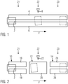
- the figure 1 shows a device for aligning piece goods 2, which are filled with flowable plastic granules and are essentially rectangular in plan view.
- the device comprises two conveyor devices 4, 6 arranged parallel next to one another, which carry the piece goods 2 together and convey them in a conveying direction F.
- the conveyors 4, 6 are presently designed as belt conveyors.
- a control unit is connected in terms of control to the conveyor devices 4, 6 and adapted in such a way that the conveyor devices 4, 6 can be driven at different speeds at times.
- a first zone Z1 in the conveying direction F the static friction between the piece goods 2 and the conveying devices 4, 6 is utilized in order to rotate it by a pre-rotation using different conveying speeds of the conveying devices 4, 6.
- a second zone Z2 which is downstream of the first zone Z1 in the conveying direction F, an optical sensor 8 for detecting the orientation of the piece goods 2, in particular the angular position of a longitudinal axis of the piece goods 2 relative to the conveying direction F, is arranged.
- the alignment of the piece goods 2 is finely adjusted in a third zone Z3 using measurement data from the sensor 8, in that the control unit drives the conveyor devices 4, 6 again at different conveying speeds.
- the third zone Z3 is in turn downstream of the second zone Z2 in the conveying direction.
- the angular position of the longitudinal axis of the piece goods 2 relative to the conveying direction F is generally 0°, ⁇ 90° or 180° after the fine adjustment.
- the figure 2 showed a device for aligning piece goods 2, which are configured as indicated above.
- the device has a first conveyor 10, a second Funding means 12 and a third funding means 14, which are arranged in the conveying direction F one behind the other.
- the first conveyor 10 has two conveyors 16, 18 arranged parallel to one another, which in the present case are designed as belt conveyors and can be driven at different speeds by a control unit, not shown, in order to rotate the piece goods 2 by a pre-rotation.
- the first conveying means 10 arranged in a first zone Z1 in the conveying direction then transfers the previously turned piece goods 2 to the second conveying means 12 which is provided in a second zone Z2 in the conveying direction.
- the second conveying means 12 is adapted to transfer the previously turned piece goods 2 without turning them to the third conveying means 14 arranged in a third zone Z3 in the conveying direction. It has a single belt conveyor 20 for this purpose. According to the second zone Z2, the third zone Z3 is located downstream in the conveying direction.
- An optical sensor 22 for detecting the alignment of the piece goods 2 previously rotated is assigned to the second conveyor 12 .
- conveyor devices 24, 26 of the third conveyor 14 arranged in parallel next to one another and designed as belt conveyors are driven by a control unit at different speeds at times in order to finely adjust the alignment of the piece goods 2.
- the essence of the two exemplary embodiments lies in the fact that the piece goods are rotated and not measured in the first and third zones, and that the piece goods are measured and not rotated in the second zone. In principle, there are no restrictions on the number of funds provided for this purpose.
Abstract
Verfahren zur Ausrichtung von Stückgütern (2), wobei ein Stückgut (2) auf zwei parallel nebeneinander angeordneten und das Stückgut (2) gemeinsam tragenden Fördereinrichtungen (4, 6; 16, 18) durch Einschalten einer zeitweisen Geschwindigkeitsdifferenz zwischen den zwei Fördereinrichtungen (4, 6; 16, 18) um eine Vorabdrehung gedreht, nach der Vorabdrehung eine Ausrichtung des Stückguts (2) ohne eine Drehung des Stückguts (2) gemessen wird und die Ausrichtung anhand der Messdaten und durch erneutes Einschalten einer zeitweisen Geschwindigkeitsdifferenz zwischen zwei parallel nebeneinander angeordneten und das Stückgut gemeinsam tragenden Fördereinrichtungen (4, 6; 24, 26) feinjustiert wird wobei um eine möglichst präzise Drehung von Stückgütern bei hoher Förderleistung zu erzielen wird die Feinjustierung in einer Zone (Z3) durchgeführt, die in Förderrichtung hinter einer Zone (Z2) angeordnet ist, in der die Messung der Ausrichtung des Stückguts (2) erfolgtMethod for aligning piece goods (2), whereby a piece good (2) is arranged on two conveyor devices (4, 6; 16, 18) which are arranged parallel next to one another and jointly carry the piece good (2) by switching on a temporary speed difference between the two conveyor devices (4, 6; 16, 18) rotated by a pre-rotation, after the pre-rotation an orientation of the piece goods (2) is measured without rotating the piece goods (2) and the orientation based on the measurement data and by switching on a temporary speed difference again between two parallel next to each other and the conveying devices (4, 6; 24, 26) that jointly carry the piece goods is finely adjusted, with the fine adjustment being carried out in a zone (Z3) which is arranged behind a zone (Z2) in the conveying direction in order to achieve the most precise possible rotation of piece goods at a high conveying capacity is, in which the measurement of the orientation of the piece goods (2) takes place
Description
Die vorliegende Erfindung betrifft eine Vorrichtung und ein Verfahren zur Ausrichtung von Stückgütern, insbesondere von mit Schüttgut befüllten Säcken.The present invention relates to a device and a method for aligning piece goods, in particular bags filled with bulk goods.
In Klappendrehvorrichtungen werden Stückgüter von Klappen, die das Stückgut an gegenüberliegenden Seiten fasst, geklemmt und gedreht. Dabei üben die Klappen eine mechanische Last am Stückgut aus, welche insbesondere bei mit Kunststoffgranulat gefüllten Säcken zu Sackdeformationen führen kann. Eine lokale Höhenvarianz der einzelnen Stückgüter führt in palettierten Stapeln zu unerwünschten Stapelschiefstellungen und Instabilität. Des Weiteren stellen die Klappen der Klappendrehvorrichtung hoch belastete und daher kostenintensive Bauteile dar, die darüber hinaus stark beschleunigende Antriebe und einen damit verbundenen Wartungsaufwand erfordern. Ein signifikanter Energieverbrauch, Vibrationen und Geräuschemissionen der Klappendrehvorrichtung sind als weitere technische Nachteile zu nennen.In flap turning devices, piece goods are clamped and rotated by flaps that hold the piece goods on opposite sides. The flaps exert a mechanical load on the piece goods, which can lead to sack deformation, particularly in the case of sacks filled with plastic granules. A local height variance of the individual piece goods leads to undesired stack tilting and instability in palletized stacks. Furthermore, the flaps of the flap turning device are highly stressed and therefore cost-intensive components, which also require strongly accelerating drives and the maintenance effort associated therewith. A significant energy consumption, vibrations and noise emissions of the flap rotation device are to be mentioned as further technical disadvantages.
Als Alternative zur Klappendrehvorrichtung finden Drehvorrichtungen mit zwei parallel nebeneinander angeordneten Förderbändern, die das Stückgut gemeinsam tragen, Anwendung. Dabei wird während der Beförderung des Stückguts die Geschwindigkeit eines der beiden Förderbänder im Vergleich zu dem anderen Förderband erhöht oder reduziert, sodass die beiden parallelen Förderbänder eine Geschwindigkeitsdifferenz aufweisen. Dies hat eine Drehung des Stückguts zur Folge, da aufgrund der Haftreibung die eine Seite des Stückguts schneller vorangetrieben wird als die andere Seite. Ist die gewünschte Drehposition erreicht, werden die Förderbänder wieder mit der gleichen Geschwindigkeit bewegt. Eine solche Drehvorrichtung ist aus
Die Förderbänder sind in der Regel verhältnismäßig lang ausgebildet, damit eine kontinuierliche Überwachung der Drehposition des Stückguts während der Drehung mittels eines über die Förderbänder gespannten Lichtvorhangs möglich ist. Dies hat Auswirkungen auf die Förderleistung, da stets nur ein Stückgut auf den parallelen Förderbändern transportiert wird und sich mit der Länge des Förderbands auch die Verweildauer des Stückguts auf demselben erhöht. Eine Verkürzung der parallelen Förderbänder in obigem Stand der Technik geht andererseits mit einer verringerten Präzision der Drehposition einher.The conveyor belts are generally designed to be relatively long, so that continuous monitoring of the rotational position of the piece goods during rotation is possible by means of a light curtain stretched over the conveyor belts. This has an impact on the conveying capacity, since only one unit load is ever transported on the parallel conveyor belts and with the length of the conveyor belt, the dwell time of the piece goods on the same increases. On the other hand, a shortening of the parallel conveyor belts in the above prior art is accompanied by a reduced precision of the rotational position.
Eine Aufgabe der vorliegenden Erfindung ist es eine Vorrichtung und ein Verfahren zur Ausrichtung von Stückgütern, insbesondere von mit Schüttgut befüllten Säcken anzugeben, die eine präzise Drehung von Stückgütern bei hoher Förderleistung ermöglichen. Die vorliegende Erfindung nimmt insbesondere die Ausrichtung von Säcken in den Blick, die mit fließfähigem Schüttgut befüllt sind, sodass eine nachträgliche Lagekorrektur innerhalb der Lage eines Stapels üblicherweise nicht möglich oder mit hohem Aufwand verbunden ist.One object of the present invention is to specify a device and a method for aligning piece goods, in particular bags filled with bulk material, which enable piece goods to be rotated precisely with a high conveying capacity. The present invention takes into account in particular the alignment of sacks that are filled with free-flowing bulk material, so that subsequent correction of the position within the position of a stack is usually not possible or involves a great deal of effort.
Zur Lösung des verfahrensmäßigen Aspekts dieser Aufgabe schlägt die vorliegende Erfindung ein Verfahren mit den Merkmalen von Anspruch 1 vor. Als gattungsgemäß für ein solches Verfahren wird die
Bei dem erfindungsgemäßen Verfahren wird ein Stückgut auf zwei parallel nebeneinander angeordneten und das Stückgut gemeinsam tragenden Fördereinrichtungen durch Einschalten einer zeitweisen Geschwindigkeitsdifferenz zwischen den zwei Fördereinrichtungen um eine Vorabdrehung gedreht. Die Vorabdrehung entspricht einer Grobausrichtung des Stückguts um einen Drehwinkel von ca. 0°, ±90° oder 180°. Die Grobausrichtung erfolgt in der Regel durch eine parametrisierte Steuerung der parallelen Fördereinrichtungen. Für gewöhnlich wird dabei die Drehposition während der Vorabdrehung nicht überwacht. Dies ermöglicht die Grobausrichtung auf einer kurzen Strecke in Förderrichtung durchzuführen.In the method according to the invention, an item is rotated by a preliminary rotation on two conveyor devices which are arranged parallel to one another and jointly carry the item by switching on a temporary speed difference between the two conveyor devices. The preliminary rotation corresponds to a rough alignment of the piece goods by a rotation angle of approx. 0°, ±90° or 180°. The rough alignment is usually done by a parameterized control of the parallel conveyors. Usually, the rotation position is not monitored during the pre-rotation. This enables the rough alignment to be carried out over a short distance in the conveying direction.
Nach der Vorabdrehung wird die Ausrichtung des vorab gedrehten Stückguts ohne Drehung des Stückguts gemessen. Die Messung erfolgt während die parallelen Fördereinrichtungen mit gleicher Geschwindigkeit angetrieben werden; d.h. ohne Drehung des Stückguts. Die Geschwindigkeit kann insbesondere auch Null (die Fördereinrichtungen stehen still) oder negativ (die Fördereinrichtungen bewegen sich entgegen der Förderrichtung) sein. Anschließend wird die Ausrichtung anhand der gemessenen Daten durch erneutes Einschalten einer zeitweisen Geschwindigkeitsdifferenz zwischen zwei parallel nebeneinander angeordneten und das Stückgut gemeinsam tragenden Fördereinrichtungen feinjustiert. Typischerweise beträgt die Winkelposition einer Längsachse des feinjustierten Stückguts 0°, ±90° oder 180° zur Förderrichtung.After the pre-rotation, the orientation of the pre-rotated article is measured without rotating the article. The measurement is made while the parallel conveyors are driven at the same speed; i.e. without rotation of the piece goods. In particular, the speed can also be zero (the conveying devices stand still) or negative (the conveying devices move in the opposite direction to the conveying direction). The alignment is then finely adjusted on the basis of the measured data by switching on a temporary speed difference again between two conveyor devices which are arranged parallel next to one another and jointly carry the piece goods. Typically, the angular position of a longitudinal axis of the finely adjusted piece goods is 0°, ±90° or 180° to the conveying direction.
Die Feinjustierung wird dabei in einer Zone durchgeführt, die in Förderrichtung hinter einer Zone angeordnet ist, in der die Messung der Ausrichtung des Stückguts erfolgt. Im Gegensatz zu dem aus
Nach einer bevorzugten Weiterbildung der vorliegenden Erfindung wird die Messung der Ausrichtung des Stückguts in einer Zone durchgeführt, die in Förderrichtung hinter der Zone angeordnet ist, in der die Vorabdrehung des Stückguts erfolgt. Hierfür kann ein separates Fördermittel für die Grobdrehung vorgesehen sein, welches das vorab gedrehte Stückgut an ein weiteres Fördermittel übergibt, so wie es grundsätzlich aus
Nach einer bevorzugten Weiterbildung der vorliegenden Erfindung wird die Feinjustierung des Stückguts und die Vorabdrehung des Stückguts auf unterschiedlichen Fördereinrichtungen durchgeführt, die für sich jedoch identisch ausgebildet sein können. Bevorzugt ist in jeder Zone ein separates Fördermittel angeordnet.According to a preferred development of the present invention, the fine adjustment of the piece goods and the pre-rotation of the piece goods are carried out on different conveyor devices, which can, however, be configured identically. A separate conveyor is preferably arranged in each zone.
Alternativ kann die Feinjustierung des Stückguts und die Vorabdrehung des Stückguts auf denselben Fördereinrichtungen durchgeführt werden. Hierfür ist in der Regel ein einzelnes Fördermittel mit zwei parallel nebeneinander angeordneten Fördereinrichtungen vorgesehen, die in Förderrichtung in einen Bereich für die Grobausrichtung, einen Bereich für das Messen der Ausrichtung und einen Bereich für die Feinjustierung der Ausrichtung unterteilt sind.Alternatively, the fine adjustment of the piece goods and the preliminary turning of the piece goods can be carried out on the same conveyor devices. For this purpose, a single conveying means is generally provided with two conveying devices arranged parallel next to one another, which are subdivided in the conveying direction into an area for rough alignment, an area for measuring the alignment and an area for fine adjustment of the alignment.
Nach einer bevorzugten Weiterbildung der vorliegenden Erfindung wird die gemessene Ausrichtung des Stückguts nach seiner Vorabdrehung zur Steuerung der zeitweisen Geschwindigkeitsdifferenz bei der Vorabdrehung eines nachfolgend beförderten Stückguts herangezogen. Dies erhöht die Präzision der Grobausrichtung, da die der Vorrichtung vorgelagerten Verpackungs- und Transportprozesse Schwankungen unterliegen, beispielsweise hinsichtlich des Sackfüllgrades oder der Sackposition auf den vorgelagerten Förderstrecken. Diese Schwankungen können mit dieser bevorzugten Weiterbildung ausgeglichen werden.According to a preferred development of the present invention, the measured orientation of the item after its pre-rotation is used to control the temporary speed difference during the pre-rotation of a subsequently conveyed item. This increases the precision of the rough alignment, since the packaging and transport processes upstream of the device are subject to fluctuations, for example with regard to the degree of sack filling or the sack position on the upstream conveyor lines. These fluctuations can be compensated for with this preferred development.
Zur Lösung des vorrichtungsmäßigen Aspekts der obigen Aufgabe gibt die vorliegende Erfindung eine Vorrichtung zur Ausrichtung von Stückgütern mit den Merkmalen von Anspruch 7 an.In order to solve the device-related aspect of the above object, the present invention specifies a device for aligning piece goods with the features of claim 7 .
Die Vorrichtung nach diesem Aspekt der Erfindung weist ein erstes Fördermittel mit mindestens zwei parallel nebeneinander angeordneten Fördereinrichtungen auf, die zur Vorabdrehung eines mit den Fördereinrichtungen zu befördernden Stückguts derart ansteuerbar sind, dass sie zeitweise eine Geschwindigkeitsdifferenz aufweisen. Als Fördereinrichtung im Sinne der vorliegenden Erfindung ist insbesondere ein Gurt-, Rollen- oder Kugelbahnförderer anzusehen.The device according to this aspect of the invention has a first conveying means with at least two conveying devices arranged parallel next to one another, which can be controlled for the pre-rotation of an item to be conveyed with the conveying devices in such a way that they temporarily have a speed difference. In particular, a belt, roller or ball track conveyor is to be regarded as a conveyor device within the meaning of the present invention.
Die Vorrichtung weist des Weiteren ein zweites Fördermittel mit zumindest einer zur Translation des Stückguts angepasst eingerichteten Fördereinrichtung auf, die das Stückgut von dem ersten Fördermittel übernimmt und an ein drittes Fördermittel übergibt, das wiederum mindestens zwei parallel nebeneinander angeordnete Fördereinrichtungen aufweist. Dem zweiten Fördermittel ist ein Sensor zur Bestimmung einer Ausrichtung des Stückguts zugeordnet, die auf dem dritten Fördermittel feinjustiert wird. Hierfür sind die Fördereinrichtungen des dritten Fördermittels anhand von Messdaten des Sensors derart ansteuerbar, dass sie zeitweise eine Geschwindigkeitsdifferenz aufweisen.The device also has a second conveying means with at least one conveying device adapted to translate the piece goods, which takes the piece goods from the first conveying means and transfers them to a third conveying means, which in turn has at least two conveying devices arranged parallel next to one another. The second conveyor is associated with a sensor for determining an orientation of the piece goods, which is finely adjusted on the third conveyor. For this purpose, the conveying devices of the third conveying means can be controlled on the basis of measurement data from the sensor in such a way that they temporarily have a speed difference.
Die Grobausrichtung des Stückguts erfolgt parametrisiert und ohne Überwachung einer Winkelposition während der Drehung, sodass das erste Fördermittel mit kurzer Förderstrecke ausgebildet sein kann. Das Stückgut wird erst auf dem zweiten Fördermittel vermessen. Das erste Fördermittel wird daher im Vergleich zu
Als Alternative und zur Lösung des vorrichtungsmäßigen Aspekts der obigen Aufgabe wird mit der vorliegenden Erfindung eine Vorrichtung mit den Merkmalen von Anspruch 9 vorgeschlagen.As an alternative and to solve the device-related aspect of the above object, a device having the features of claim 9 is proposed with the present invention.
Die Vorrichtung nach diesem Aspekt der Erfindung weist ein einzelnes Fördermittel mit mindestens zwei parallel nebeneinander angeordneten und gemeinsam ein Stückgut tragenden Fördereinrichtungen, die derart ansteuerbar sind, dass sie zeitweise eine Geschwindigkeitsdifferenz aufweisen, um das Stückgut zu drehen, einen Sensor zur Bestimmung einer Ausrichtung des vorab gedrehten Stückguts, und eine die Geschwindigkeitsdifferenz der Fördereinrichtungen steuernde Steuerungseinrichtung auf. Die Steuerungseinrichtung ist dazu angepasst eingerichtet, die zwei Fördereinrichtungen in einem Grobausrichtungsmodus so anzusteuern, dass sie zeitweise eine Geschwindigkeitsdifferenz aufweisen, um das Stückgut um eine Vorabdrehung zu drehen, eine Ausrichtung des vorab gedrehten Stückguts bei gleicher Geschwindigkeit der zwei Fördereinrichtungen durch den Sensor zu messen und die Ausrichtung in einem Feinausrichtungsmodus anhand von Messdaten des Sensors durch erneutes Einschalten einer zeitweisen Geschwindigkeitsdifferenz zwischen den zwei Fördereinrichtungen feinzujustieren. Dabei wird die Ausrichtung des Stückguts während oder nach der Feinjustierung üblicherweise nicht gemessen.The device according to this aspect of the invention has a single conveying means with at least two conveying devices arranged parallel to one another and jointly carrying a piece good, which can be controlled in such a way that they temporarily have a speed difference in order to rotate the piece good, a sensor for determining an orientation of the previously rotated piece goods, and a control device controlling the speed difference of the conveyor devices. The control device is adapted to control the two conveyors in a rough alignment mode so that they temporarily have a speed difference in order to rotate the piece goods by a pre-rotation, to measure an alignment of the previously rotated piece goods at the same speed of the two conveyors by the sensor, and to finely adjust the alignment in a fine alignment mode based on measurement data from the sensor by switching on a temporary speed difference between the two conveyor devices again. The alignment of the piece goods is usually not measured during or after the fine adjustment.
Es können grundsätzlich mehr als zwei Fördereinrichtungen vorgesehen sein, die parallel zueinander angeordnet sind und von denen mindestens eine mit einer steuerbaren Geschwindigkeit antreibbar ist. Wie grundsätzlich aus
Der Sensor zur Messung der Ausrichtung des Stückguts ist in der Regel ein optischer Sensor. Er kann beispielsweise wie der aus
Die Vorrichtung nach der vorliegenden Erfindung ist zur Anwendung im Bereich der Verpackungstechnik zur lagenweisen Anordnung von insbesondere rechteckigen Stückgütern auf Paletten vorgesehen. Insbesondere mit Schüttgut befüllte Säcke werden bevorzugt in einem Verband aus mehreren Lagen auf einer Palette angeordnet. Zur Bildung der einzelnen Lagen werden die Säcke in einer ersten Orientierung oder in einer zweiten Orientierung, in der der Gegenstand gegenüber der ersten Orientierung um 90° gedreht ist, oder gegebenenfalls in einer dritten Orientierung, in der der Gegenstand gegenüber der ersten Orientierung um 180° gedreht ist, nebeneinander in einer Ebene angeordnet.The device according to the present invention is intended for use in the field of packaging technology for the layered arrangement of, in particular, rectangular piece goods on pallets. In particular, sacks filled with bulk material are preferably arranged in a combination of several layers on a pallet. To form the individual layers, the bags are placed in a first orientation or in a second orientation in which the object is rotated 90° with respect to the first orientation, or optionally in a third orientation, in which the object is rotated 180° with respect to the first orientation, arranged next to one another in one plane.
Weitere Einzelheiten und Vorteile der vorliegenden Erfindung ergeben sich aus der nachfolgenden Beschreibung von Ausführungsbeispielen in Verbindung mit der Zeichnung. In dieser zeigen:
Figur 1- eine schematische Darstellung eines Ausführungsbeispiels in der Draufsicht, und
Figur 2- eine schematische Darstellung eines anderen Ausführungsbeispiels in der Draufsicht.
- figure 1
- a schematic representation of an embodiment in plan view, and
- figure 2
- a schematic representation of another embodiment in plan view.
Die
Eine nicht dargestellte Steuerungseinheit ist steuerungsmäßig mit den Fördereinrichtungen 4, 6 steuerungsmäßig verbunden und derart angepasst eingerichtet, dass die Fördereinrichtungen 4, 6 zeitweise unterschiedlich schnell angetrieben werden können. In einer ersten Zone Z1 in Förderrichtung F wird die Haftreibung zwischen dem Stückgut 2 und den Fördereinrichtungen 4, 6 ausgenutzt, um es durch unterschiedliche Fördergeschwindigkeiten der Fördereinrichtungen 4, 6 um eine Vorabdrehung zu drehen. In einer zweiten Zone Z2, die der ersten Zone Z1 in Förderrichtung F nachgelagert ist, ist ein optischer Sensor 8 zur Erfassung der Ausrichtung des Stückguts 2, insbesondere der Winkelposition einer Längsachse des Stückguts 2 relativ zur Förderrichtung F, angeordnet. Die Ausrichtung des Stückguts 2 wird in einer dritten Zone Z3 anhand von Messdaten des Sensors 8 feinjustiert, indem die Steuerungseinheit die Fördereinrichtungen 4, 6 erneut zeitweise mit unterschiedlicher Fördergeschwindigkeit antreibt. Die dritte Zone Z3 ist wiederum der zweiten Zone Z2 in Förderrichtung nachgelagert.A control unit, not shown, is connected in terms of control to the
Die Winkelpositionen der Längsachse des Stückguts 2 relativ zur Förderrichtung F beträgt nach der Feinjustierung in der Regel 0°, ±90° oder 180°. Vorliegend ist in
Die
Das zweite Fördermittel 12 ist dazu angepasst eingerichtet, das vorab gedrehte Stückgut 2 ohne Drehung an das in einer dritten Zone Z3 in Förderrichtung angeordnete dritte Fördermittel 14 zu übergeben. Es weist hierfür einen einzelnen Gurtförderer 20 auf. Die dritte Zone Z3 ist entsprechend der zweiten Zone Z2 in Förderrichtung nachgelagert. Ein optischer Sensor 22 zur Erfassung der Ausrichtung des vorab gedrehten Stückguts 2 ist dem zweiten Fördermittel 12 zugeordnet. Auf Basis der von dem Sensor 22 gemessenen Daten werden parallel nebeneinander angeordnete und als Gurtförderer ausgebildete Fördereinrichtungen 24, 26 des dritten Fördermittels 14 von einer Steuerungseinheit zeitweise unterschiedlich schnell angetrieben, um die Ausrichtung des Stückguts 2 feinzujustieren.The second conveying
Das Wesen der beiden Ausführungsbeispiele liegt darin, dass das Stückgut in der ersten und der dritten Zone gedreht und nicht gemessen wird und dass das Stückgut in der zweiten Zone gemessen und nicht gedreht wird. Die Anzahl der hierfür vorgesehenen Fördermittel unterliegt grundsätzlich keiner Einschränkung.The essence of the two exemplary embodiments lies in the fact that the piece goods are rotated and not measured in the first and third zones, and that the piece goods are measured and not rotated in the second zone. In principle, there are no restrictions on the number of funds provided for this purpose.
- 22
- Stückgutgeneral cargo
- 4,64.6
- Fördereinrichtungconveyor
- 88th
- optischer Sensoroptical sensor
- 1010
- erstes Fördermittelfirst grant
- 1212
- zweites Fördermittelsecond grant
- 1414
- drittes Fördermittelthird grant
- 16, 1816, 18
- Fördereinrichtungconveyor
- 2020
- Gurtfördererbelt conveyor
- 2222
- optischer Sensoroptical sensor
- 24, 2624, 26
- Fördereinrichtungconveyor
- Ff
- Förderrichtungconveying direction
- Z1Z1
- erste Zonefirst zone
- Z2Z2
- zweite Zonesecond zone
- Z3Z3
- dritte Zonethird zone
Claims (9)
ein erstes Fördermittel (10) mit zumindest zwei parallel nebeneinander angeordneten Fördereinrichtungen (16, 18), die zum Vorabdrehen eines mit den Fördereinrichtungen (16, 18) zu befördernden Stückguts (2) derart ansteuerbar sind, dass sie zeitweise eine Geschwindigkeitsdifferenz aufweisen,
gekennzeichnet durch
ein zweites, dem ersten Fördermittel (10) in Förderrichtung nachgelagertes Fördermittel (12) mit zumindest einer Fördereinrichtung (20), die zur Translation des vorab gedrehten Stückguts (2) zu einem dritten Fördermittel (14) angepasst ausgebildet ist,
einen dem zweiten Fördermittel (12) zugeordneten Sensor (22) zur Messung einer Ausrichtung des vorab gedrehten Stückguts (2), und
das dritte Fördermittel (14), das dem zweiten Fördermittel (12) in Förderrichtung nachgelagert ist und zumindest zwei parallel nebeneinander angeordnete und das vorab gedrehte Stückgut gemeinsam tragende Fördereinrichtungen (24, 26) aufweist, die zur Feinjustierung der Ausrichtung anhand von Messdaten des Sensors (22) derart ansteuerbar sind, dass sie zeitweise eine Geschwindigkeitsdifferenz aufweisen.Having a device for aligning piece goods (2), in particular sacks filled with bulk goods
a first conveying means (10) with at least two conveying devices (16, 18) arranged parallel next to one another, which can be controlled for the pre-rotation of an item (2) to be conveyed with the conveying devices (16, 18) in such a way that they temporarily have a speed difference,
marked by
a second conveyor (12), downstream of the first conveyor (10) in the conveying direction, with at least one conveyor device (20), which is adapted to translate the previously rotated piece goods (2) to a third conveyor (14),
a sensor (22) assigned to the second conveying means (12) for measuring an alignment of the previously rotated piece goods (2), and
the third conveying means (14), which is downstream of the second conveying means (12) in the conveying direction and has at least two conveying devices (24, 26) which are arranged parallel next to one another and jointly carry the previously rotated piece goods, which are used for fine adjustment of the alignment using measurement data from the sensor ( 22) can be controlled in such a way that they temporarily have a speed difference.
zumindest zwei parallel nebeneinander angeordnete Fördereinrichtungen (4, 6), die zeitweise mit unterschiedlicher Geschwindigkeit antreibbar sind, um ein auf den Fördereinrichtungen (4, 6) zu beförderndes Stückgut (2) zu drehen,
einen Sensor (8) zur Messung einer Ausrichtung des gedrehten Stückguts (2), und
eine die Antriebsgeschwindigkeit der Fördereinrichtungen (4, 6) steuernde Steuerungseinrichtung,
dadurch gekennzeichnet, dass die Steuerungseinrichtung dazu angepasst eingerichtet ist,
die Fördereinrichtungen (4, 6) in einem Grobausrichtungsmodus so anzusteuern, dass sie zeitweise eine Geschwindigkeitsdifferenz aufweisen, um das Stückgut (2) um eine Vorabdrehung zu drehen, eine Ausrichtung des vorab gedrehten Stückguts (2) bei gleicher Geschwindigkeit der Fördereinrichtungen mit dem Sensor (8) zu messen und die Ausrichtung in einem Feinausrichtungsmodus anhand von Messdaten des Sensors (8) durch erneutes Einschalten einer zeitweisen Geschwindigkeitsdifferenz zwischen den Fördereinrichtungen (4, 6) feinzujustieren.Having a device for aligning piece goods (2), in particular sacks filled with bulk goods
at least two conveyor devices (4, 6) arranged parallel next to one another, which can be driven at different speeds at times in order to rotate an item (2) to be conveyed on the conveyor devices (4, 6),
a sensor (8) for measuring an alignment of the rotated piece goods (2), and
a control device that controls the drive speed of the conveyor devices (4, 6),
characterized in that the control device is adapted to
to control the conveyor devices (4, 6) in a rough alignment mode in such a way that they temporarily have a speed difference in order to rotate the item (2) by a pre-rotation, an alignment of the previously rotated item (2) at the same speed of the conveyor devices with the sensor ( 8) to measure and to finely adjust the alignment in a fine alignment mode using measurement data from the sensor (8) by switching on a temporary speed difference between the conveyor devices (4, 6) again.
Priority Applications (1)
| Application Number | Priority Date | Filing Date | Title |
|---|---|---|---|
| EP20195086.2A EP3964460A1 (en) | 2020-09-08 | 2020-09-08 | Device and method for aligning piece goods |
Applications Claiming Priority (1)
| Application Number | Priority Date | Filing Date | Title |
|---|---|---|---|
| EP20195086.2A EP3964460A1 (en) | 2020-09-08 | 2020-09-08 | Device and method for aligning piece goods |
Publications (1)
| Publication Number | Publication Date |
|---|---|
| EP3964460A1 true EP3964460A1 (en) | 2022-03-09 |
Family
ID=72432743
Family Applications (1)
| Application Number | Title | Priority Date | Filing Date |
|---|---|---|---|
| EP20195086.2A Withdrawn EP3964460A1 (en) | 2020-09-08 | 2020-09-08 | Device and method for aligning piece goods |
Country Status (1)
| Country | Link |
|---|---|
| EP (1) | EP3964460A1 (en) |
Cited By (1)
| Publication number | Priority date | Publication date | Assignee | Title |
|---|---|---|---|---|
| EP4299485A1 (en) * | 2022-07-01 | 2024-01-03 | Deutsche Post AG | Device for aligning or aligning. rotating objects |
Citations (4)
| Publication number | Priority date | Publication date | Assignee | Title |
|---|---|---|---|---|
| EP1180484A2 (en) | 2000-08-16 | 2002-02-20 | NWU-Benelux B.V. | Fine alignment station and method for its operation |
| DE202011110089U1 (en) | 2011-10-20 | 2012-11-28 | Beumer Gmbh & Co. Kg | Device for aligning a non-circular or polygonal object |
| JP6170969B2 (en) * | 2015-07-08 | 2017-07-26 | 冨士島工機株式会社 | Food direction change device |
| DE102017120730A1 (en) * | 2017-09-08 | 2019-03-14 | Khs Gmbh | Device and method for aligning containers |
-
2020
- 2020-09-08 EP EP20195086.2A patent/EP3964460A1/en not_active Withdrawn
Patent Citations (4)
| Publication number | Priority date | Publication date | Assignee | Title |
|---|---|---|---|---|
| EP1180484A2 (en) | 2000-08-16 | 2002-02-20 | NWU-Benelux B.V. | Fine alignment station and method for its operation |
| DE202011110089U1 (en) | 2011-10-20 | 2012-11-28 | Beumer Gmbh & Co. Kg | Device for aligning a non-circular or polygonal object |
| JP6170969B2 (en) * | 2015-07-08 | 2017-07-26 | 冨士島工機株式会社 | Food direction change device |
| DE102017120730A1 (en) * | 2017-09-08 | 2019-03-14 | Khs Gmbh | Device and method for aligning containers |
Cited By (1)
| Publication number | Priority date | Publication date | Assignee | Title |
|---|---|---|---|---|
| EP4299485A1 (en) * | 2022-07-01 | 2024-01-03 | Deutsche Post AG | Device for aligning or aligning. rotating objects |
Similar Documents
| Publication | Publication Date | Title |
|---|---|---|
| DE69506499T3 (en) | Sorting system with cross band | |
| EP2106376B1 (en) | Intelligent accumulating conveyor | |
| EP1456101B1 (en) | Method and device for forming rows of packed goods | |
| DE102007036020A1 (en) | Aligning food products | |
| EP3115322A1 (en) | Method and device for depalletizing tires | |
| DE202011110089U1 (en) | Device for aligning a non-circular or polygonal object | |
| EP3287396A1 (en) | Conveyor system with segments | |
| EP3357839A1 (en) | Method and conveyor system for manipulating an original flow of goods | |
| EP3516349A1 (en) | Weighing apparatus and method for weighing a product | |
| EP3395728A1 (en) | Configuration of the distance between goods to be conveyed | |
| EP0527542B1 (en) | Conveyor system with multiple feed lines | |
| EP3786089A1 (en) | Device and method for conveying and sorting piece goods | |
| EP3964460A1 (en) | Device and method for aligning piece goods | |
| DE102017206995A1 (en) | Handling device and method for handling in at least one row of moving piece goods | |
| EP3678964A1 (en) | Device and method for orienting packages | |
| EP3947215B1 (en) | Method and conveying apparatus for the improved determination of the position of an object transported on the conveying apparatus | |
| EP1940711B1 (en) | Device and method for arranging stacks of flat objects on pallets | |
| EP3196154A1 (en) | Conveying system for goods comprising an alignment device | |
| DE102018009134B4 (en) | Telescopic conveyor with integrated timing and measuring conveyor | |
| DE4315053A1 (en) | Device for reversing the direction of flat mail items | |
| DE102006023988B3 (en) | Arrangement for accelerating or decelerating unit load items transported in conveyor system, which are motor driven in which transport unit load items currently located between belts, are accelerated | |
| WO2017198354A1 (en) | Conveying portion for conveying material to be sorted in different directions | |
| CH719300A1 (en) | Process and device for phase-accurate transfer of piece goods. | |
| DE102004047018B4 (en) | Device for the positionally accurate transfer of objects from a conveyor belt to a mobile transport member | |
| EP4302884A1 (en) | Device for aligning objects |
Legal Events
| Date | Code | Title | Description |
|---|---|---|---|
| PUAI | Public reference made under article 153(3) epc to a published international application that has entered the european phase |
Free format text: ORIGINAL CODE: 0009012 |
|
| STAA | Information on the status of an ep patent application or granted ep patent |
Free format text: STATUS: THE APPLICATION HAS BEEN PUBLISHED |
|
| AK | Designated contracting states |
Kind code of ref document: A1 Designated state(s): AL AT BE BG CH CY CZ DE DK EE ES FI FR GB GR HR HU IE IS IT LI LT LU LV MC MK MT NL NO PL PT RO RS SE SI SK SM TR |
|
| STAA | Information on the status of an ep patent application or granted ep patent |
Free format text: STATUS: THE APPLICATION IS DEEMED TO BE WITHDRAWN |
|
| 18D | Application deemed to be withdrawn |
Effective date: 20220910 |