EP3964436A1 - Straddled vehicle - Google Patents
Straddled vehicle Download PDFInfo
- Publication number
- EP3964436A1 EP3964436A1 EP21194523.3A EP21194523A EP3964436A1 EP 3964436 A1 EP3964436 A1 EP 3964436A1 EP 21194523 A EP21194523 A EP 21194523A EP 3964436 A1 EP3964436 A1 EP 3964436A1
- Authority
- EP
- European Patent Office
- Prior art keywords
- vehicle
- regard
- upper cover
- lower cover
- cover
- Prior art date
- Legal status (The legal status is an assumption and is not a legal conclusion. Google has not performed a legal analysis and makes no representation as to the accuracy of the status listed.)
- Granted
Links
Images




Classifications
-
- B—PERFORMING OPERATIONS; TRANSPORTING
- B62—LAND VEHICLES FOR TRAVELLING OTHERWISE THAN ON RAILS
- B62K—CYCLES; CYCLE FRAMES; CYCLE STEERING DEVICES; RIDER-OPERATED TERMINAL CONTROLS SPECIALLY ADAPTED FOR CYCLES; CYCLE AXLE SUSPENSIONS; CYCLE SIDECARS, FORECARS, OR THE LIKE
- B62K21/00—Steering devices
- B62K21/02—Front wheel forks or equivalent, e.g. single tine
-
- B—PERFORMING OPERATIONS; TRANSPORTING
- B62—LAND VEHICLES FOR TRAVELLING OTHERWISE THAN ON RAILS
- B62J—CYCLE SADDLES OR SEATS; AUXILIARY DEVICES OR ACCESSORIES SPECIALLY ADAPTED TO CYCLES AND NOT OTHERWISE PROVIDED FOR, e.g. ARTICLE CARRIERS OR CYCLE PROTECTORS
- B62J17/00—Weather guards for riders; Fairings or stream-lining parts not otherwise provided for
- B62J17/10—Ventilation or air guiding devices forming part of fairings
-
- B—PERFORMING OPERATIONS; TRANSPORTING
- B62—LAND VEHICLES FOR TRAVELLING OTHERWISE THAN ON RAILS
- B62J—CYCLE SADDLES OR SEATS; AUXILIARY DEVICES OR ACCESSORIES SPECIALLY ADAPTED TO CYCLES AND NOT OTHERWISE PROVIDED FOR, e.g. ARTICLE CARRIERS OR CYCLE PROTECTORS
- B62J23/00—Other protectors specially adapted for cycles
-
- B—PERFORMING OPERATIONS; TRANSPORTING
- B62—LAND VEHICLES FOR TRAVELLING OTHERWISE THAN ON RAILS
- B62K—CYCLES; CYCLE FRAMES; CYCLE STEERING DEVICES; RIDER-OPERATED TERMINAL CONTROLS SPECIALLY ADAPTED FOR CYCLES; CYCLE AXLE SUSPENSIONS; CYCLE SIDECARS, FORECARS, OR THE LIKE
- B62K25/00—Axle suspensions
- B62K25/04—Axle suspensions for mounting axles resiliently on cycle frame or fork
- B62K25/06—Axle suspensions for mounting axles resiliently on cycle frame or fork with telescopic fork, e.g. including auxiliary rocking arms
- B62K25/08—Axle suspensions for mounting axles resiliently on cycle frame or fork with telescopic fork, e.g. including auxiliary rocking arms for front wheel
Definitions
- the present invention relates to a straddled vehicle having a front fork.
- a cover (hereinafter referred to as a "front fork cover”) has been installed on a front fork in order to prevent, for example, mud from adhering to the front fork and pebbles from hitting the front fork.
- a front fork cover is known in the art that is formed so that a part of its cross section is formed in a streamlined shape.
- the front fork cover is integrated with the number plate and extends downward from the number plate.
- the front fork cover has a front half portion and a rear half portion, and the cross-sectional shape of the rear half portion is formed in a streamlined shape.
- the cross-sectional shape of the front half portion is formed in a semicircular shape
- the cross-sectional shape of the rear half portion is formed in a rearwardly-elongated shape.
- the wind generated while the straddled vehicle is running flows smoothly around the front fork cover. This allows the wind to be desirably supplied to the radiator, etc., arranged rearward of the front fork.
- the front fork includes a pair of telescopic suspensions, each having an inner tube and an outer tube, on the left and on the right. Since the suspension is an elongated component, the dimension of the suspension in the vehicle up-down direction is large. While the front fork cover disclosed in JP 08-332982A covers an upper portion of the suspension but does not cover a lower portion thereof. Since the front fork cover is integrated with the number plate, it is difficult to extend the front fork cover downward so as to cover the substantial portion of the suspension. Therefore, with the front fork cover described above, it is not possible to cover the substantial portion of the suspension.
- the cross-sectional shape of the rear half portion is a streamlined shape, but the cross-sectional shape of the front half portion is a circular shape and not a streamlined shape. Therefore, in order to further improve the airflow straightening function, one may consider forming the cross-sectional shape of the front half portion in a streamlined shape. That is, one may consider forming both the front half portion and the rear half portion so that the dimension of the cross-sectional shape in the vehicle front-rear direction is larger than a half of the dimension thereof in the vehicle left-right direction.
- the dimension of the front fork cover in the vehicle front-rear direction becomes large, and the front fork cover receives more wind pressure from a diagonal direction.
- the front fork cover rotates, together with the front fork, about the steering shaft. Then, the wind hits the front fork cover from an inclined direction.
- the wind pressure received by the front fork cover varies depending on the rotation angle of the front fork. Therefore, if the dimension of the front fork cover in the vehicle front-rear direction is excessive, the wind pressure to be received while steering may become substantially not constant, thereby deteriorating the handling comfort.
- An object of the present invention is to provide a straddled vehicle, with which it is possible to better prevent mud, pebbles, etc., from hitting the front fork than before, to desirably send wind to vehicle components that are rearward of the front fork, and to maintain the handling comfort.
- said object is solved by a straddled vehicle having the features of independent claim 1. Preferred embodiments are laid down in the dependent claims.
- a straddled vehicle disclosed herein includes: a front wheel; a front fork including a left and a right telescopic suspension each having a lower tube supported on the front wheel and an upper tube slidable on the lower tube; a vehicle component arranged rearward of the front fork; a lower cover covering at least a part of the lower tube; and an upper cover separate from the lower cover and covering at least a part of the upper tube.
- An upper end of the lower cover is located upward relative to a lower end of the upper cover.
- a cross section of the upper cover perpendicular to an axial line of the suspension includes an upper cover front portion located forward relative to the axial line of the suspension and an upper cover rear portion located rearward relative to the axial line of the suspension.
- a cross section of the lower cover perpendicular to the axial line of the suspension includes a lower cover front portion located forward relative to the axial line of the suspension and a lower cover rear portion located rearward relative to the axial line of the suspension.
- the upper cover front portion includes a first front edge, a first left edge extending rearward and leftward from the first front edge, and a first right edge extending rearward and rightward from the first front edge.
- a dimension of the upper cover front portion in a vehicle front-rear direction is larger than a half of a dimension of the upper cover front portion in a vehicle left-right direction.
- the upper cover rear portion has a shape of which a rear side is open.
- a dimension of the upper cover rear portion in the vehicle front-rear direction is smaller than the dimension of the upper cover front portion in the vehicle front-rear direction.
- the lower cover front portion includes a third front edge, a third left edge extending rearward and leftward from the third front edge, and a third right edge extending rearward and rightward from the third front edge.
- a dimension of the lower cover front portion in the vehicle front-rear direction is larger than a half of a dimension of the lower cover front portion in the vehicle left-right direction.
- the lower cover rear portion has a shape of which a rear side is open.
- a dimension of the lower cover rear portion in the vehicle front-rear direction is smaller than the dimension of the lower cover front portion in the vehicle front-rear direction.
- the straddled vehicle includes an upper cover and a lower cover covering the suspension of the front fork, and the upper cover and the lower cover are separate parts.
- the cross sections of the upper cover and the lower cover perpendicular to the axial line of the suspension are not circular, but are each formed in a shape that is obtained by cutting off a portion of a streamlined shape at a position rearward relative to the axial line of the suspension.
- the upper cover and the lower cover each have a shape that conforms to a streamlined shape and extend to a position rearward relative to the axial line of the suspension.
- the upper cover and the lower cover can sufficiently straighten the airflow from the front side.
- a sufficiently straightened air is supplied to vehicle components that are rearward of the front fork.
- the cross section of each of the upper cover and the lower cover is formed in a shape that is obtained by cutting off a rear portion of a streamlined shape, the dimension thereof in the vehicle front-rear direction is smaller than that when the entirety thereof is formed in a streamlined shape. Therefore, as compared with a case where the entirety of the cross section of each of the upper cover and the lower cover is formed in a streamlined shape, the wind pressure to be received by the upper cover and the lower cover from the side is small.
- the upper cover rear portion may include a second left edge extending rearward and rightward, and a second right edge located rightward of the second left edge and extending rearward and leftward.
- the lower cover rear portion may include an edge extending rearward and inward in the vehicle width direction from a position that is outward in a vehicle width direction relative to the lower tube.
- the lower cover rear portion may include another edge extending rearward and outward in the vehicle width direction from a position that is inward in the vehicle width direction relative to the lower tube.
- the straddled vehicle includes a front fender including a horizontal portion arranged upward of the front wheel, and a vertical portion that extends downward from the horizontal portion and is arranged sideward of the front wheel.
- the lower cover is arranged rearward of the vertical portion of the front fender.
- a cross section of the vertical portion of the front fender perpendicular to the axial line of the suspension includes a fourth front edge, a fourth left edge extending rearward and leftward from the fourth front edge and a fourth right edge extending rearward and rightward from the fourth front edge, wherein a dimension of the vertical portion in the vehicle front-rear direction is larger than a half of a dimension thereof in the vehicle left-right direction.
- the front fender With the front fender, it is possible to prevent mud from being rolled up from the front wheel, and it is possible to improve the air guide function for components that are rearward of the front fork.
- the straddled vehicle includes a front fender that is arranged upward of the front wheel and integrated with a left lower cover and a right lower cover.
- the lower cover serve also as the vertical portion of the front fender, it is possible to reduce the number of components.
- an upper end of the lower cover is located upward relative to an upper end of the lower tube.
- a lower end of the lower cover is located downward relative to a middle position of the lower tube in a vehicle up-down direction.
- the lower cover covers a half or more of the lower tube. Therefore, for a large portion of the lower tube, it is possible to prevent mud, pebbles, etc., from hitting the lower tube.
- the front wheel includes a rim and a tire attached to the rim.
- the upper end of the lower cover is located upward relative to the rim as the vehicle is viewed from the side.
- the lower cover extends to a relatively high position. Therefore, it is possible to effectively prevent mud, pebbles, etc., from hitting the suspension.
- an upper end of the tire is located downward relative to an upper end of the vehicle component and upward relative to a lower end of the vehicle component.
- a portion of the upper cover, a portion of the lower cover and a portion of the tire overlap with each other as the vehicle is viewed from the side.
- the suspension may be an inverted suspension. That is, the upper tube may be a cylindrical outer tube; and the lower tube may be an inner tube slidably inserted into the outer tube.
- a lower end portion of the upper cover is arranged on an inner side of an upper end portion of the lower cover.
- the muddy water when muddy water is rolled up from the road surface to adhere to the lower cover, the muddy water is likely to move along the surface of the lower cover and reach the upper end portion of the lower cover to be then scattered rearward by the wind. Therefore, it is possible to suppress adhesion of muddy water to the suspension.
- the straddled vehicle includes: an under bracket secured to the upper tube of the left suspension and the upper tube of the right suspension; and an inner fender secured to the under bracket.
- the upper cover is supported on the inner fender; and the lower cover is supported on the lower tube.
- the upper cover and the lower cover are desirably supported.
- the inner fender includes a horizontal plate-shaped air guide portion arranged downward of the under bracket.
- the upper cover extends downward from the air guide portion.
- the air guide portion of the inner fender and the left and right upper covers together form a gate-shaped air guide path for guiding airflow rearward.
- the air guide path it is possible to more desirably send wind to components that are rearward of the front fork.
- the straddled vehicle includes a cowling at least a part of which is arranged outward in a vehicle width direction relative to the upper cover. A portion of the upper cover and a portion of the cowling overlap with each other as the vehicle is viewed from the side.
- a front end of the upper cover is located forward relative to a front end of the cowling.
- the airflow is guided into between the upper cover and the cowling after being straightened by at least a part of the upper cover. It is possible to more desirably send wind to vehicle components that are rearward of the front fork.
- a front end of the upper cover may be located forward relative to a front end of the cowling, and a rear end of the upper cover may be located rearward relative to the front end of the cowling.
- the dimension of the upper cover front portion in the vehicle front-rear direction may be equal to or greater than the dimension of the upper cover front portion in the vehicle left-right direction.
- the dimension of the lower cover front portion in the vehicle front-rear direction may be equal to or greater than the dimension of the lower cover front portion in the vehicle left-right direction.
- the dimension of the upper cover rear portion in the vehicle front-rear direction may be 1/4 to 3/4 times a dimension of the upper cover rear portion in the vehicle left-right direction.
- the dimension of the lower cover rear portion in the vehicle front-rear direction may be 1/4 to 3/4 times a dimension of the lower cover rear portion in the vehicle left-right direction.
- a radiator or an oil cooler is an example of the vehicle component. Other components can be taken into consideration.
- the present invention it is possible to provide a straddled vehicle, with which it is possible to better prevent mud, pebbles, etc., from hitting the front fork than before, to desirably send wind to vehicle components that are rearward of the front fork, and to maintain the handling comfort.
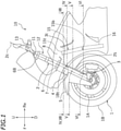
- FIG. 1 is a left side view showing a front portion of a motorcycle 10 according to the present embodiment.
- F, Re, L, R, U and D refer to front, rear, left, right, up and down, respectively.
- the motorcycle 10 includes a front wheel 1, a front fork 12 supported on the front wheel 1, a steering shaft 11 supported on the front fork 12, and a handle 13 secured to the steering shaft 11.
- a cowling 8 is arranged forward and sideward of the front fork 12.
- a radiator 15 and an oil cooler 16 are arranged rearward of the front fork 12.
- the radiator 15 and the oil cooler 16 are examples of vehicle components arranged rearward of the front fork 12.
- the oil cooler 16 is arranged downward of the radiator 15.
- the motorcycle 10 includes a head pipe, a body frame extending rearward from the head pipe, an internal combustion engine supported on the body frame, a seat supported on the body frame, a rear arm pivotally supported on the body frame, and a rear wheel supported on the rear arm.
- the steering shaft 11 is inserted through the head pipe.
- the steering shaft 11 is rotatably supported on the head pipe.
- the seat is arranged rearward of the head pipe.
- the head pipe is arranged upward of the internal combustion engine.
- the front fork 12 includes a left and a right telescopic suspension 2.
- FIG. 2 is a perspective view showing the front wheel 1, etc., as viewed from a left and forward diagonal direction.
- FIG. 3 is a perspective view showing the front wheel 1, etc., as viewed from a left and rearward diagonal direction.
- an under bracket 6 and an upper bracket 6B arranged upward relative to the under bracket 6 are secured to the left suspension 2 and to the right suspension 2.
- the under bracket 6 and the upper bracket 6B bridge between the left and right suspensions 2.
- reference sign 25 denotes a stroke sensor for detecting the amount of extension/contraction of the suspension 2. Note that in FIG. 3 , the stroke sensor 25 is not shown.
- a front fender 5 is arranged forward of the front fork 12.
- the front fender 5 includes a horizontal portion 51 arranged upward of the front wheel 1, a vertical portion 52 that extends downward from the left end of the horizontal portion 51 and is arranged on the left side of the front wheel 1, and a vertical portion 52 that extends downward from the right end of the horizontal portion 51 and is arranged on the right side of the front wheel 1.
- each suspension 2 includes an outer tube 2B, and an inner tube 2A slidably inserted into the outer tube 2B.
- the front fork 12 is a so-called inverted front fork, with the inner tube 2A arranged downward and the outer tube 2B arranged upward.
- the inner tube 2A and the outer tube 2B are an example of the “lower tube” and an example of the "upper tube”, respectively.
- the motorcycle 10 includes left and right lower covers 3 covering at least a part of the left and right inner tubes 2A, and left and right upper covers 4 covering at least a part of the left and right outer tubes 2B.
- the left upper cover 4 is separate from the left lower cover 3.
- the right upper cover 4 is separate from the right lower cover 3.
- the left upper cover 4 and the left lower cover 3 have a left-right symmetrical configuration with the right upper cover 4 and the right lower cover 3, respectively.
- the configuration of the left upper cover 4 and the configuration of the left lower cover 3 will be described, while omitting the description of the configuration of the right upper cover 4 and the configuration of the right lower cover 3.
- FIG. 4 is a cross-sectional view taken along line IV-IV of FIG. 1 , showing the suspension 2 and the upper cover 4.
- the cross section of the suspension 2 and the upper cover 4 shown in FIG. 4 is a cross section perpendicular to the axial line 2c of the suspension 2.
- the axial line 2c of the suspension 2 refers to the axial line of the inner tube 2A and the outer tube 2B.
- the cross section of the upper cover 4 perpendicular to the axial line 2c of the suspension 2 includes an upper cover front portion 41 located forward relative to the axial line 2c of the suspension 2, and an upper cover rear portion 42 located rearward relative to the axial line 2c of the suspension 2.
- the upper cover front portion 41 is formed in a streamlined shape with its dimension in the vehicle left-right direction gradually decreasing toward the front side.
- the upper cover front portion 41 is formed with the front side closed.
- the upper cover front portion 41 includes a first front edge 41F, a first left edge 41L extending rearward and leftward from the first front edge 41F, and a first right edge 41R extending rearward and rightward from the first front edge 41F.
- the upper cover front portion 41 is formed in a streamlined shape, and it is more elongated in the forward direction than a semicircular shape.
- the dimension L41 of the upper cover front portion 41 in the vehicle front-rear direction is larger than a half of the dimension W41 of the upper cover front portion 41 in the vehicle left-right direction. L41>0.5 ⁇ W41.
- the dimension L41 of the upper cover front portion 41 in the vehicle front-rear direction is larger than the dimension W41 of the upper cover front portion 41 in the vehicle left-right direction. L41>W41.
- the upper cover rear portion 42 is formed so that its dimension in the vehicle left-right direction gradually decreases toward the rear side.
- the upper cover rear portion 42 is shaped with an opening toward the rear side.
- the upper cover rear portion 42 is formed in a shape that is obtained by cutting off a rear portion of the streamlined shape denoted by the virtual line 42x.
- the upper cover rear portion 42 has a shape that conforms to the streamlined shape.
- the upper cover rear portion 42 includes a second left edge 42L and a second right edge 42R.
- the second left edge 42L extends rearward and rightward from the first left edge 41L.
- the second right edge 42R extends rearward and leftward from the first right edge 41R.
- the second left edge 42L extends rearward and inward in the vehicle width direction from a position that is outward in the vehicle width direction relative to the outer tube 2B.
- the second right edge 42R extends rearward and outward in the vehicle width direction from a position that is inward in the vehicle width direction relative to the outer tube 2B.
- the dimension L42 of the upper cover rear portion 42 in the vehicle front-rear direction is smaller than the dimension L41 of the upper cover front portion 41 in the vehicle front-rear direction.
- the dimension of the second left edge 42L in the vehicle front-rear direction and the dimension of the second right edge 42R in the vehicle front-rear direction may be equal to or different from each other.
- the dimension of the second right edge 42R in the vehicle front-rear direction is larger than the dimension of the second left edge 42L in the vehicle front-rear direction.
- the dimension L42 of the upper cover rear portion 42 in the vehicle front-rear direction is 1/4 to 3/4 times the dimension W42 of the upper cover rear portion 42 in the vehicle left-right direction.
- FIG. 5 is a cross-sectional view taken along line V-V of FIG. 1 , showing the suspension 2, the upper cover 4 and the lower cover 3.
- the cross section of the suspension 2, the upper cover 4 and the lower cover 3 shown in FIG. 5 is a cross section perpendicular to the axial line 2c of the suspension 2.
- the lower cover 3 has a shape similar to the upper cover 4. Note however that in the cross section, the lower cover 3 is slightly larger than the upper cover 4.
- the upper cover 4 is arranged on the inner side of the lower cover 3.
- the cross section of the lower cover 3 perpendicular to the axial line 2c of the suspension 2 includes a lower cover front portion 31 that is located forward relative to the axial line 2c of the suspension 2, and a lower cover rear portion 32 that is located rearward relative to the axial line 2c of the suspension 2.
- the lower cover front portion 31 is formed in a streamlined shape with its dimension in the vehicle left-right direction gradually decreasing toward the front side.
- the lower cover front portion 31 is formed with the front side closed.
- the lower cover front portion 31 includes a third front edge 31F, a third left edge 31L extending rearward and leftward from the third front edge 31F, and a third right edge 31R extending rearward and rightward from the third front edge 31F.
- the lower cover front portion 31 is formed in a streamlined shape, and it is more elongated in the forward direction than a semicircular shape.
- the dimension L31 of the lower cover front portion 31 in the vehicle front-rear direction is larger than a half of the dimension W31 of the lower cover front portion 31 in the vehicle left-right direction. L31>0.5 ⁇ W31.
- the dimension L31 of the lower cover front portion 31 in the vehicle front-rear direction is larger than the dimension W31 of the lower cover front portion 31 in the vehicle left-right direction. L31>W31.
- the lower cover rear portion 32 is formed so that its dimension in the vehicle left-right direction gradually decreases toward the rear side.
- the lower cover rear portion 32 is shaped with an opening toward the rear side.
- the lower cover rear portion 32 is formed in a shape that is obtained by cutting off a rear portion of the streamlined shape.
- the lower cover rear portion 32 has a shape that conforms to the streamlined shape.
- the lower cover rear portion 32 includes a left edge 32L and a right edge 32R.
- the left edge 32L extends rearward and rightward from the third left edge 31L.
- the right edge 32R extends rearward and leftward from the third right edge 31R.
- the left edge 32L extends rearward and inward in the vehicle width direction from a position that is outward in the vehicle width direction relative to the outer tube 2B.
- the right edge 32R extends rearward and outward in the vehicle width direction from a position that is inward in the vehicle width direction relative to the outer tube 2B.
- the dimension L32 of the lower cover rear portion 32 in the vehicle front-rear direction is smaller than the dimension L31 of the lower cover front portion 31 in the vehicle front-rear direction.
- the dimension of the left edge 32L in the vehicle front-rear direction and the dimension of the right edge 32R in the vehicle front-rear direction may be equal to or different from each other.
- the dimension of the right edge 32R in the vehicle front-rear direction is larger than the dimension of the left edge 32L in the vehicle front-rear direction.
- the dimension L32 of the lower cover rear portion 32 in the vehicle front-rear direction is 1/4 to 3/4 times the dimension W32 of the lower cover rear portion 32 in the vehicle left-right direction.
- FIG. 6 is a cross-sectional view taken along line VI-VI of FIG. 1 , showing the suspension 2, the lower cover 3, the front fender 5, etc.
- the cross section of the suspension 2, the lower cover 3 and the front fender 5 shown in FIG. 6 is a cross section perpendicular to the axial line 2c of the suspension 2.
- the lower cover 3 is arranged rearward of the vertical portion 52 of the front fender 5.
- the cross-sectional shape of the lower cover 3 shown in FIG. 6 is different from the cross-sectional shape of the lower cover 3 shown in FIG. 5 .
- the rear end of the third right edge 31R of the lower cover front portion 31 is located forward relative to the axial line 2c of the suspension 2.
- the lower cover rear portion 32 does not have the right edge 32R.
- Reference sign 55 denotes a brake disc.
- the right edge 32R of the lower cover rear portion 32 is omitted so that the brake disc 55 does not interfere with the lower cover 3.
- the lower cover rear portion 32 may have the right edge 32R as long as it does not interfere with the brake disc 55.
- the cross section of the vertical portion 52 of the front fender 5 perpendicular to the axial line 2c of the suspension 2 is formed so that its dimension in the vehicle left-right direction gradually decreases toward the front side, and is formed in a shape that is obtained by cutting off a rear portion of a streamlined shape.
- the cross section of the vertical portion 52 of the front fender 5 perpendicular to the axial line 2c of the suspension 2 includes a fourth front edge 52F, a fourth left edge 52L extending rearward and leftward from the fourth front edge 52F, and a fourth right edge 52R extending rearward and rightward from the fourth front edge 52F.
- the dimension L52 of the vertical portion 52 in the vehicle front-rear direction is larger than a half of the dimension W52 of the vertical portion 52 in the vehicle left-right direction. L52>0.5 ⁇ W52.
- the right vertical portion 52 of the front fender 5 is formed in a shape that is in left-right symmetry with the left vertical portion 52 described above.
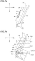
- FIG. 7a is a side view showing the suspension 2 and the lower cover 3.
- FIG. 7b is a side view showing the suspension 2 and the upper cover 4.
- FIG. 7c is a side view showing the suspension 2, the front fender 5 and the upper cover 4.
- Reference sign 3tH denotes a horizontal line that passes through an upper end 3t of the lower cover 3.
- Reference sign 4bH denotes a horizontal line that passes through a lower end 4b of the upper cover 4.
- the upper end 3t of the lower cover 3 is located upward relative to a lower end 4b of the upper cover 4.
- the upper end portion of the lower cover 3 and the lower end portion of the upper cover 4 overlap with each other as viewed from the side.
- the lower end portion of the upper cover 4 is inserted on the inner side of the upper end portion of the lower cover 3.
- Reference sign 2AtH denotes a horizontal line that passes through an upper end 2At of the inner tube 2A.
- the upper end 2At of the inner tube 2A refers to the upper end of a portion of the inner tube 2A that protrudes from the outer tube 2B when the motorcycle 10 is stationary standing upright on a horizontal surface with no rider and no load thereon. Since the upper end portion of the inner tube 2A is inserted into the outer tube 2B, the inner tube 2A includes a portion that is located upward relative to the upper end 2At. However, the upper end 2At described above is herein defined as the upper end of the inner tube 2A. As shown in FIG. 7b , the upper end 3t of the lower cover 3 is located upward relative to the upper end 2At of the inner tube 2A.
- Reference sign 2AmH denotes a horizontal line that passes through a middle position 2Am of the inner tube 2A in the vehicle up-down direction.
- the middle position 2Am of the inner tube 2A in the vehicle up-down direction refers to the middle position in the vehicle up-down direction along a portion of the inner tube 2A that protrudes from the outer tube 2B when the motorcycle 10 is stationary standing upright on a horizontal surface with no rider and no load thereon.
- Reference sign 3bH denotes a horizontal line that passes through a lower end 3b of the lower cover 3. As shown in FIG. 7b , the lower end 3b of the lower cover 3 is located downward relative to the middle position 2Am of the inner tube 2A in the vehicle up-down direction.
- the front wheel 1 includes a rim 1A and a tire 1B attached to the rim 1A.
- An upper end 1Bt of the tire 1B is located downward relative to an upper end 15t of the radiator 15 and upward relative to a lower end 15b of the radiator 15.
- the upper end 3t of the lower cover 3 is located upward relative to the rim 1A.
- a portion of the upper cover 4, a portion of the lower cover 3 and a portion of the tire 1B overlap with each other.
- an inner fender 7 is secured to the under bracket 6.
- the inner fender 7 includes a horizontal plate-shaped air guide portion 7A, and an air guide portion 7B extending rearward and upward from the rear end of the air guide portion 7A.
- a front end 7Af of the air guide portion 7A is located forward relative to a front end 6f of the under bracket 6.
- the upper cover 4 is supported on the inner fender 7.
- the upper cover 4 is supported on the outer tube 2B of the suspension 2 via the inner fender 7 and the under bracket 6.
- the lower cover 3 is supported on the inner tube 2A of the suspension 2 via a bracket 35 (see FIG. 7a and FIG. 7b ).
- the upper cover 4 is supported on the outer tube 2B and is not supported on the inner tube 2A.
- the lower cover 3 is supported on the inner tube 2A and is not supported on the outer tube 2B. Therefore, when the inner tube 2A slides against the outer tube 2B, no external force is applied to the upper cover 4 and the lower cover 3.
- the upper cover 4 extends downward from the air guide portion 7A.
- the left and right upper covers 4 and the air guide portion 7A together define a gate-shaped air guide path 17.
- FIG. 8 is a cross-sectional view taken along line VIII-VIII of FIG. 1 , for the upper cover 4, the cowling 8, etc.
- FIG. 8 shows a horizontal cross section that passes through the middle position of the upper cover 4 in the vehicle up-down direction.
- a front end 4f of the upper cover 4 is located forward relative to a front end 8f of the cowling 8.
- a rear end 4r of the upper cover 4 is located rearward relative to a front end 8f of the cowling 8.
- the radiator 15 is arranged rearward of the front fender 5, the upper cover 4 and the lower cover 3.
- the oil cooler 16 is arranged rearward of the front fender 5, the upper cover 4 and the lower cover 3.
- the wind flows from the front side against the motorcycle 10.
- the radiator 15 and the oil cooler 16 are cooled by the wind from the front side.
- the radiator 15 and the oil cooler 16 are arranged rearward of the front fork 12. If the wind is disturbed while flowing around the front fork 12, it will deteriorate the function of cooling the radiator 15 and the oil cooler 16.
- the cross-sectional contours of the outer tube 2B and the inner tube 2A of the front fork 12 are circular.
- many vortices are formed rearward of the outer tube 2B.
- a disturbed airflow is supplied to the radiator 15, thereby deteriorating the cooling function of the radiator 15.
- the upper cover 4 having a shape that is obtained by cutting off a rear portion of a streamlined shape is provided as shown in FIG. 9b .
- a relatively straightened airflow is supplied to the radiator 15. This suppresses the deterioration of the cooling function of the radiator 15.
- the entirety of the upper cover 4 has a streamlined shape as shown in FIG. 9c , there is little disturbance of the airflow. In such a case, a significantly straightened airflow is supplied to the radiator 15. In order to enhance the cooling function of the radiator 15, it is preferred that the entirety of the upper cover 4 has a streamlined shape. However, when the entirety of the upper cover 4 has a streamlined shape, the dimension of the upper cover 4 in the vehicle front-rear direction is large. Therefore, the upper cover 4 receives more wind pressure from a diagonal direction. When the rider steers the handle 13 (see FIG. 1 ), the front fork 12 and the upper cover 4 rotate leftward or rightward. As shown in FIG.
- the upper cover 4 is formed in a shape that is obtained by cutting off a rear portion of a streamlined shape. Therefore, the dimension of the upper cover 4 in the vehicle front-rear direction is smaller than that when the entirety of the upper cover 4 is formed in a streamlined shape. In the present embodiment, the upper cover 4 receives less wind pressure from a diagonal direction. Therefore, as shown in FIG. 11a and FIG. 11b , the difference in the wind pressure received by the upper cover 4 is relatively small between when the motorcycle 10 is running straight and when the upper cover 4 rotates rightward. This suppresses the change in the wind pressure received by the upper cover 4 while the rider rotates the handle 13. Therefore, the upper cover 4 according to the present embodiment suppresses the deterioration of the cooling function of the radiator 15 while ensuring the handling comfort.
- the motorcycle 10 according to one embodiment has been described above. Next, various effects realized by the motorcycle 10 of the present embodiment will be described.
- the motorcycle 10 includes the upper cover 4 and the lower cover 3 covering the suspension 2 of the front fork 12.
- the upper cover 4 is a separate part from the lower cover 3, and is separate from the lower cover 3.
- two covers i.e., the upper cover 4 and the lower cover 3 that are separated from each other in the vehicle up-down direction, it is possible to cover a large portion of the suspension 2. Therefore, it is possible to better prevent mud, pebbles, etc., from hitting the suspension 2 than before.
- the cross sections of the upper cover 4 and the lower cover 3 are not circular, but are each formed in a shape that is obtained by cutting off a portion of a streamlined shape at a position rearward relative to the axial line 2c of the suspension 2.
- the upper cover 4 and the lower cover 3 each have a shape that conforms to a streamlined shape and extend to a position rearward relative to the axial line 2c of the suspension 2, and it is therefore possible to sufficiently straighten the airflow from the front side.
- a sufficiently straightened air is supplied to the radiator 15 and the oil cooler 16. Therefore, it is possible to suppress the deterioration of the cooling function of the radiator 15 and the oil cooler 16.
- the dimensions of the upper cover 4 and the lower cover 3 in the vehicle front-rear direction are each smaller as compared with a case where the entirety thereof is formed in a streamlined shape. Therefore, the wind pressure received by the upper cover 4 and the lower cover 3 from a diagonal direction is smaller as compared with a case where the cross sections of the upper cover 4 and the lower cover 3 are each entirely formed in a streamlined shape. It is possible to suppress the change in the wind pressure received by the upper cover 4 and the lower cover 3 while the rider rotates the handle 13. Therefore, the handling comfort is ensured.
- the motorcycle 10 it is possible to better prevent mud, pebbles, etc., from hitting the front fork 12 than before, it is possible to desirably supply air to the radiator 15 and the oil cooler 16 arranged rearward of the front fork 12, and it is possible to maintain the handling comfort.
- the lower cover rear portion 32 may include only one of the left edge 32L and the right edge 32R (see FIG. 6 ) or may include both of them (see FIG. 5 ). If the lower cover rear portion 32 includes both of the left edge 32L and the right edge 32R, it is possible to further improve the air guide function of the lower cover 3.
- the motorcycle 10 includes the front fender 5, and the cross section of the front fender 5 perpendicular to the axial line 2c of the suspension 2 has a shape that conforms to a streamlined shape. That is, as shown in FIG. 5 and FIG. 6 , the cross section of the front fender 5 includes the fourth left edge 52L extending rearward and leftward from the fourth front edge 52F and the fourth right edge 52R extending rearward and rightward from the fourth front edge 52F, with the dimension L52 in the vehicle front-rear direction being larger than a half of the dimension W52 thereof in the vehicle left-right direction. With the front fender 5, it is possible to prevent mud from being rolled up from the front wheel 1, and it is possible to improve the air guide function for the radiator 15 and the oil cooler 16.
- the upper end 3t of the lower cover 3 is located upward relative to the upper end 2At of the inner tube 2A, and the lower end 3b is located downward relative to the middle position 2Am of the inner tube 2A in the vehicle up-down direction.
- the lower cover 3 covers a half or more of the inner tube 2A. Therefore, for a large portion of the inner tube 2A, it is possible to prevent mud, pebbles, etc., from hitting the inner tube 2A.
- the upper end 3t of the lower cover 3 is located upward relative to the rim 1A of the front wheel 1.
- the lower cover 3 extends to a relatively high position. Therefore, it is possible to effectively prevent mud, pebbles, etc., from hitting the suspension 2.
- the lower end portion of the upper cover 4 is arranged inward of the upper end portion of the lower cover 3 (see FIG. 7b ).
- the muddy water is likely to move along the surface of the lower cover 3 and reach the upper end portion of the lower cover 3 to be then scattered rearward by the wind. Therefore, it is possible to prevent muddy water from entering inside the lower cover 3 and the upper cover 4. Thus, it is possible to suppress adhesion of muddy water to the suspension 2.
- the upper cover 4 is supported on the inner fender 7, and the lower cover 3 is supported on the inner tube 2A. Therefore, it is possible to desirably support the upper cover 4 and the lower cover 3.
- the inner fender 7 includes the horizontal plate-shaped air guide portion 7A, and the upper cover 4 extends downward from the air guide portion 7A.
- the air guide portion 7A and the left and right upper covers 4 together form a gate-shaped air guide path 17 for guiding airflow rearward.
- FIG. 1 As shown in FIG. 1 , as the vehicle is viewed from the side, a portion of the upper cover 4 and a portion of the cowling 8 overlap with each other. With the upper cover 4 and the cowling 8, it is possible to desirably straighten the airflow from the front side (see reference sign A1 in FIG. 9b ). Therefore, it is possible to more desirably supply air to the radiator 15.
- the front end 4f of the upper cover 4 is located forward relative to the front end 8f of the cowling 8.
- the upper cover 4 and the cowling 8 it is possible to desirably straighten the airflow from the front side. It is possible to more desirably supply air to the radiator 15.
- the front fender 5 includes the left vertical portion 52 arranged leftward of the front wheel 1, the right vertical portion 52 arranged rightward of the front wheel 1, and the horizontal portion 51 arranged upward of the front wheel 1.
- the vertical portion 52 of the front fender 5 and the lower cover 3 are formed as separate parts. Note however that the lower cover 3 does not need to be separate from the front fender 5.
- the front fender 5 may be integrated with the left lower cover 3 and the right lower cover 3.
- the lower cover 3 may serve also as a part of the front fender 5.
- the lower cover 3 may form the vertical portion of the front fender 5.
- the front fender 5 may include the left lower cover 3 arranged leftward of the front wheel 1, the right lower cover 3 arranged rightward of the front wheel 1, and the horizontal portion 51 arranged upward of the front wheel 1.
- the lower cover 3 may be an integral part with the horizontal portion 51. As the front fender 5 is integrated with the lower cover 3, it is possible to reduce the number of components.
- the second left edge 42L of the upper cover rear portion 42 extends rearward and rightward from the rear end of the first left edge 41L of the upper cover front portion 41.
- the second right edge 42R of the upper cover rear portion 42 extends rearward and leftward from the rear end of the first right edge 41R of the upper cover front portion 41.
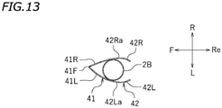
- the upper cover rear portion 42 may include another left edge 42La extending rearward and leftward from the rear end of the first left edge 41L of the upper cover front portion 41, and the second left edge 42L may extend rearward and rightward from the rear end of the other left edge 42La.
- the upper cover rear portion 42 may include another right edge 42Ra extending rearward and rightward from the rear end of the first right edge 41R of the upper cover front portion 41, and the second right edge 42R may extend rearward and leftward from the rear end of the other right edge 42Ra.
- the left edge 32L of the lower cover rear portion 32 extends rearward and rightward from the rear end of the third left edge 31L of the lower cover front portion 31.
- the third right edge 32R of the lower cover rear portion 32 extends rearward and leftward from the rear end of the third right edge 31R of the lower cover front portion 31.
- the lower cover rear portion 32 may include another left edge extending rearward and leftward from the rear end of the third left edge 31L of the lower cover front portion 31, and the left edge 32L may extend rearward and rightward from the rear end of the other left edge.
- the lower cover rear portion 32 may include another right edge extending rearward and rightward from the rear end of the third right edge 31R of the lower cover front portion 31, and the right edge 32R may extend rearward and leftward from the rear end of the other right edge.
- the front fork 12 is an inverted front fork, and the inner tube 2A is arranged downward of the outer tube 2B.
- the front fork 12 may be a non-inverted front fork. That is, the inner tube 2A may be arranged upward of the outer tube 2B. In such a case, the inner tube 2A is the "upper tube”, and the outer tube 2B is the "lower tube”.
- the vertical portion 52 of the front fender 5 includes the left edge 52L and the right edge 52R in the embodiment described above, the vertical portion 52 arranged leftward of the front wheel 1 does not need to include the right edge 52R. That is, the vertical portion 52 may only have an edge that is located outward in the vehicle width direction.
- the front fender 5 may only include the horizontal portion 51 and not include the vertical portion 52.
- the upper end 3t of the lower cover 3 may be located downward relative to the upper end of the lower tube (the upper end 2At of the inner tube 2A in the embodiment described above).
- the lower end 3b of the lower cover 3 may be located upward relative to the middle position of the lower tube in the vehicle up-down direction (the middle position 2Am of the inner tube 2A in the vehicle up-down direction in the embodiment described above).
- the upper end 3t of the lower cover 3 may be located downward relative to the upper end of the rim 1A of the front wheel 1.
- a portion of the upper cover 4, a portion of the lower cover 3 and a portion of the tire 1B does not need to overlap with each other.
- the upper end portion of the lower cover 3 may be arranged inward of the lower end portion of the upper cover 4.
- the member for supporting the upper cover 4 may be supported on a component other than the inner fender 7.
- the lower cover 3 may be supported on a component other than the inner tube 2A.
- the inner fender 7 may be optional.
- the inner fender 7 may be absent.
- the upper cover 4 and the cowling 8 do not need to overlap with each other.
- the front end 4f of the upper cover 4 in a horizontal cross section that passes through the middle position of the upper cover 4 in the vehicle up-down direction, is located forward relative to the front end 8f of the cowling 8.
- the front end 4f of the upper cover 4 may be located forward relative to the front end 8f of the cowling 8.
- the front end 4f of the upper cover 4 does not need to be located forward relative to the front end 8f of the cowling 8.
- the front end 4f of the upper cover 4 may be located rearward relative to the front end 8f of the cowling 8.
- the rear end 4r of the upper cover 4 may be located forward relative to the front end 8f of the cowling 8. With the motorcycle 10, there may be no need for the cowling 8.
- radiator 15 and the oil cooler 16 may be absent. Instead of or together with the radiator 15 and the oil cooler 16, other components to be cooled by the airflow may be arranged.
- the straddled vehicle is not limited to the motorcycle 10.
- the straddled vehicle may be an auto tricycle, an ATV (All Terrain Vehicle), or a snowmobile, for example.
- ATV All Terrain Vehicle
Landscapes
- Engineering & Computer Science (AREA)
- Mechanical Engineering (AREA)
- Axle Suspensions And Sidecars For Cycles (AREA)
- Automatic Cycles, And Cycles In General (AREA)
Abstract
Description
- The present invention relates to a straddled vehicle having a front fork.
- A cover (hereinafter referred to as a "front fork cover") has been installed on a front fork in order to prevent, for example, mud from adhering to the front fork and pebbles from hitting the front fork.
- As disclosed in
JP 08-332982A - The front fork includes a pair of telescopic suspensions, each having an inner tube and an outer tube, on the left and on the right. Since the suspension is an elongated component, the dimension of the suspension in the vehicle up-down direction is large. While the front fork cover disclosed in
JP 08-332982A - With the front fork cover described above, the cross-sectional shape of the rear half portion is a streamlined shape, but the cross-sectional shape of the front half portion is a circular shape and not a streamlined shape. Therefore, in order to further improve the airflow straightening function, one may consider forming the cross-sectional shape of the front half portion in a streamlined shape. That is, one may consider forming both the front half portion and the rear half portion so that the dimension of the cross-sectional shape in the vehicle front-rear direction is larger than a half of the dimension thereof in the vehicle left-right direction.
- In such a case, however, the dimension of the front fork cover in the vehicle front-rear direction becomes large, and the front fork cover receives more wind pressure from a diagonal direction. With a straddled vehicle, when the rider steers the handle, the front fork cover rotates, together with the front fork, about the steering shaft. Then, the wind hits the front fork cover from an inclined direction. The wind pressure received by the front fork cover varies depending on the rotation angle of the front fork. Therefore, if the dimension of the front fork cover in the vehicle front-rear direction is excessive, the wind pressure to be received while steering may become substantially not constant, thereby deteriorating the handling comfort.
- An object of the present invention is to provide a straddled vehicle, with which it is possible to better prevent mud, pebbles, etc., from hitting the front fork than before, to desirably send wind to vehicle components that are rearward of the front fork, and to maintain the handling comfort. According to the present invention said object is solved by a straddled vehicle having the features of
independent claim 1. Preferred embodiments are laid down in the dependent claims. - A straddled vehicle disclosed herein includes: a front wheel; a front fork including a left and a right telescopic suspension each having a lower tube supported on the front wheel and an upper tube slidable on the lower tube; a vehicle component arranged rearward of the front fork; a lower cover covering at least a part of the lower tube; and an upper cover separate from the lower cover and covering at least a part of the upper tube. An upper end of the lower cover is located upward relative to a lower end of the upper cover. A cross section of the upper cover perpendicular to an axial line of the suspension includes an upper cover front portion located forward relative to the axial line of the suspension and an upper cover rear portion located rearward relative to the axial line of the suspension. A cross section of the lower cover perpendicular to the axial line of the suspension includes a lower cover front portion located forward relative to the axial line of the suspension and a lower cover rear portion located rearward relative to the axial line of the suspension. The upper cover front portion includes a first front edge, a first left edge extending rearward and leftward from the first front edge, and a first right edge extending rearward and rightward from the first front edge. A dimension of the upper cover front portion in a vehicle front-rear direction is larger than a half of a dimension of the upper cover front portion in a vehicle left-right direction. The upper cover rear portion has a shape of which a rear side is open. A dimension of the upper cover rear portion in the vehicle front-rear direction is smaller than the dimension of the upper cover front portion in the vehicle front-rear direction. The lower cover front portion includes a third front edge, a third left edge extending rearward and leftward from the third front edge, and a third right edge extending rearward and rightward from the third front edge. A dimension of the lower cover front portion in the vehicle front-rear direction is larger than a half of a dimension of the lower cover front portion in the vehicle left-right direction. The lower cover rear portion has a shape of which a rear side is open. A dimension of the lower cover rear portion in the vehicle front-rear direction is smaller than the dimension of the lower cover front portion in the vehicle front-rear direction.
- The straddled vehicle includes an upper cover and a lower cover covering the suspension of the front fork, and the upper cover and the lower cover are separate parts. With the upper cover and the lower cover, it is possible to cover a large portion of the suspension. Therefore, it is possible to better prevent mud, pebbles, etc., from hitting the suspension than before. The cross sections of the upper cover and the lower cover perpendicular to the axial line of the suspension are not circular, but are each formed in a shape that is obtained by cutting off a portion of a streamlined shape at a position rearward relative to the axial line of the suspension. The upper cover and the lower cover each have a shape that conforms to a streamlined shape and extend to a position rearward relative to the axial line of the suspension. Therefore, the upper cover and the lower cover can sufficiently straighten the airflow from the front side. Thus, a sufficiently straightened air is supplied to vehicle components that are rearward of the front fork. It is possible to desirably send wind to vehicle components that are rearward of the front fork. Since the cross section of each of the upper cover and the lower cover is formed in a shape that is obtained by cutting off a rear portion of a streamlined shape, the dimension thereof in the vehicle front-rear direction is smaller than that when the entirety thereof is formed in a streamlined shape. Therefore, as compared with a case where the entirety of the cross section of each of the upper cover and the lower cover is formed in a streamlined shape, the wind pressure to be received by the upper cover and the lower cover from the side is small. This suppresses the change in the wind pressure received by the upper cover and the lower cover while the front fork rotates leftward or rightward. Thus, the handling comfort is ensured. Therefore, with the straddled vehicle set forth above, it is possible to better prevent mud, pebbles, etc., from hitting the front fork than before, to desirably send wind to vehicle components that are rearward of the front fork, and to maintain the handling comfort.
- The upper cover rear portion may include a second left edge extending rearward and rightward, and a second right edge located rightward of the second left edge and extending rearward and leftward.
- The lower cover rear portion may include an edge extending rearward and inward in the vehicle width direction from a position that is outward in a vehicle width direction relative to the lower tube.
- The lower cover rear portion may include another edge extending rearward and outward in the vehicle width direction from a position that is inward in the vehicle width direction relative to the lower tube.
- According to a preferred embodiment, the straddled vehicle includes a front fender including a horizontal portion arranged upward of the front wheel, and a vertical portion that extends downward from the horizontal portion and is arranged sideward of the front wheel. The lower cover is arranged rearward of the vertical portion of the front fender. A cross section of the vertical portion of the front fender perpendicular to the axial line of the suspension includes a fourth front edge, a fourth left edge extending rearward and leftward from the fourth front edge and a fourth right edge extending rearward and rightward from the fourth front edge, wherein a dimension of the vertical portion in the vehicle front-rear direction is larger than a half of a dimension thereof in the vehicle left-right direction.
- According to the embodiment set forth above, with the front fender, it is possible to prevent mud from being rolled up from the front wheel, and it is possible to improve the air guide function for components that are rearward of the front fork.
- According to a preferred embodiment, the straddled vehicle includes a front fender that is arranged upward of the front wheel and integrated with a left lower cover and a right lower cover.
- According to the embodiment set forth above, since the lower cover serve also as the vertical portion of the front fender, it is possible to reduce the number of components.
- According to a preferred embodiment, an upper end of the lower cover is located upward relative to an upper end of the lower tube. A lower end of the lower cover is located downward relative to a middle position of the lower tube in a vehicle up-down direction.
- According to the embodiment set forth above, the lower cover covers a half or more of the lower tube. Therefore, for a large portion of the lower tube, it is possible to prevent mud, pebbles, etc., from hitting the lower tube.
- According to a preferred embodiment, the front wheel includes a rim and a tire attached to the rim. The upper end of the lower cover is located upward relative to the rim as the vehicle is viewed from the side.
- According to the embodiment set forth above, the lower cover extends to a relatively high position. Therefore, it is possible to effectively prevent mud, pebbles, etc., from hitting the suspension.
- According to a preferred embodiment, an upper end of the tire is located downward relative to an upper end of the vehicle component and upward relative to a lower end of the vehicle component. A portion of the upper cover, a portion of the lower cover and a portion of the tire overlap with each other as the vehicle is viewed from the side.
- According to the embodiment set forth above, it is possible to desirably send wind to vehicle components even if the suspension extends/contracts while the straddled vehicle is running.
- The suspension may be an inverted suspension. That is, the upper tube may be a cylindrical outer tube; and the lower tube may be an inner tube slidably inserted into the outer tube.
- According to a preferred embodiment, a lower end portion of the upper cover is arranged on an inner side of an upper end portion of the lower cover.
- According to the embodiment set forth above, when muddy water is rolled up from the road surface to adhere to the lower cover, the muddy water is likely to move along the surface of the lower cover and reach the upper end portion of the lower cover to be then scattered rearward by the wind. Therefore, it is possible to suppress adhesion of muddy water to the suspension.
- According to a preferred embodiment, the straddled vehicle includes: an under bracket secured to the upper tube of the left suspension and the upper tube of the right suspension; and an inner fender secured to the under bracket. The upper cover is supported on the inner fender; and the lower cover is supported on the lower tube.
- According to the embodiment set forth above, the upper cover and the lower cover are desirably supported.
- According to a preferred embodiment, the inner fender includes a horizontal plate-shaped air guide portion arranged downward of the under bracket. The upper cover extends downward from the air guide portion.
- According to the embodiment set forth above, the air guide portion of the inner fender and the left and right upper covers together form a gate-shaped air guide path for guiding airflow rearward. With the air guide path, it is possible to more desirably send wind to components that are rearward of the front fork.
- According to a preferred embodiment, the straddled vehicle includes a cowling at least a part of which is arranged outward in a vehicle width direction relative to the upper cover. A portion of the upper cover and a portion of the cowling overlap with each other as the vehicle is viewed from the side.
- According to the embodiment set forth above, with the upper cover and the cowling, it is possible to desirably straighten the airflow from the front side. It is possible to more desirably send wind to vehicle components that are rearward of the front fork.
- According to a preferred embodiment, in a predetermined horizontal cross section that passes through the upper cover, a front end of the upper cover is located forward relative to a front end of the cowling.
- According to the embodiment set forth above, the airflow is guided into between the upper cover and the cowling after being straightened by at least a part of the upper cover. It is possible to more desirably send wind to vehicle components that are rearward of the front fork.
- In a predetermined horizontal cross section that passes through the upper cover, a front end of the upper cover may be located forward relative to a front end of the cowling, and a rear end of the upper cover may be located rearward relative to the front end of the cowling.
- The dimension of the upper cover front portion in the vehicle front-rear direction may be equal to or greater than the dimension of the upper cover front portion in the vehicle left-right direction. The dimension of the lower cover front portion in the vehicle front-rear direction may be equal to or greater than the dimension of the lower cover front portion in the vehicle left-right direction.
- The dimension of the upper cover rear portion in the vehicle front-rear direction may be 1/4 to 3/4 times a dimension of the upper cover rear portion in the vehicle left-right direction. The dimension of the lower cover rear portion in the vehicle front-rear direction may be 1/4 to 3/4 times a dimension of the lower cover rear portion in the vehicle left-right direction.
- A radiator or an oil cooler is an example of the vehicle component. Other components can be taken into consideration.
- According to the present invention, it is possible to provide a straddled vehicle, with which it is possible to better prevent mud, pebbles, etc., from hitting the front fork than before, to desirably send wind to vehicle components that are rearward of the front fork, and to maintain the handling comfort.
-
-
FIG. 1 is a side view showing a front portion of a motorcycle according to an embodiment. -
FIG. 2 is a perspective view showing a front wheel, etc., of the motorcycle as viewed from a left and forward diagonal direction. -
FIG. 3 is a perspective view showing the front wheel, etc., of the motorcycle as viewed from a left diagonal direction. -
FIG. 4 is a cross-sectional view taken along line IV-IV ofFIG. 1 , showing a left suspension, an upper cover, etc. -
FIG. 5 is a cross-sectional view taken along line V-V ofFIG. 1 , showing the left suspension, the upper cover, a lower cover, etc. -
FIG. 6 is a cross-sectional view taken along line V-V ofFIG. 1 , showing the left suspension, the lower cover, a front fender, etc. -
FIG. 7a is a side view showing the suspension and the lower cover.FIG. 7b is a side view showing the suspension and the upper cover.FIG. 7c is a side view showing the suspension, the front fender and the upper cover. -
FIG. 8 is a cross-sectional view taken along line VIII-VIII ofFIG. 1 , showing the upper cover, a cowling, etc. -
FIG. 9a is a view schematically showing the air flow forward of a radiator in the absence of an upper cover.FIG. 9b is a view schematically showing the air flow forward of the radiator in the presence of an upper cover according to an embodiment.FIG. 9c is a view schematically showing the air flow forward of the radiator in the presence of an upper cover of a streamlined shape. -
FIG. 10a is a view schematically showing the air flow when the front fork is facing forward in the presence of an upper cover of a streamlined shape.FIG. 10b is a view schematically showing the air flow when the front fork rotates rightward in the presence of an upper cover of a streamlined shape. -
FIG. 11a is a view schematically showing the air flow when the front fork is facing forward in the presence of an upper cover according to an embodiment.FIG. 11b is a view schematically showing the air flow when the front fork rotates rightward in the presence of an upper cover according to an embodiment. -
FIG. 12 is a view corresponding toFIG. 5 according to another embodiment. -
FIG. 13 is a view corresponding toFIG. 4 showing a left suspension and an upper cover according to another embodiment. - An embodiment of the present teaching will now be described with reference to the drawings. A motorcycle will now be described as an example of a straddled vehicle. Note that a straddled vehicle refers to a vehicle that is straddled by the rider.
FIG. 1 is a left side view showing a front portion of amotorcycle 10 according to the present embodiment. - The designations F, Re, L, R, U and D, as used in the figures, refer to front, rear, left, right, up and down, respectively. The terms front, rear, left, right, up and down, as used in the description below, refer to these directions as seen from the rider seated in the seat (not shown) while the
motorcycle 10 is stationary standing upright on a horizontal surface with no rider and no load thereon, unless specified otherwise. - The
motorcycle 10 includes afront wheel 1, afront fork 12 supported on thefront wheel 1, a steeringshaft 11 supported on thefront fork 12, and ahandle 13 secured to the steeringshaft 11. Acowling 8 is arranged forward and sideward of thefront fork 12. Aradiator 15 and anoil cooler 16 are arranged rearward of thefront fork 12. Theradiator 15 and theoil cooler 16 are examples of vehicle components arranged rearward of thefront fork 12. Theoil cooler 16 is arranged downward of theradiator 15. - Although not shown in the figures, the
motorcycle 10 includes a head pipe, a body frame extending rearward from the head pipe, an internal combustion engine supported on the body frame, a seat supported on the body frame, a rear arm pivotally supported on the body frame, and a rear wheel supported on the rear arm. The steeringshaft 11 is inserted through the head pipe. The steeringshaft 11 is rotatably supported on the head pipe. The seat is arranged rearward of the head pipe. The head pipe is arranged upward of the internal combustion engine. - The
front fork 12 includes a left and a righttelescopic suspension 2.FIG. 2 is a perspective view showing thefront wheel 1, etc., as viewed from a left and forward diagonal direction.FIG. 3 is a perspective view showing thefront wheel 1, etc., as viewed from a left and rearward diagonal direction. As shown inFIG. 3 , an underbracket 6 and anupper bracket 6B arranged upward relative to the underbracket 6 are secured to theleft suspension 2 and to theright suspension 2. The underbracket 6 and theupper bracket 6B bridge between the left andright suspensions 2. InFIG. 2 ,reference sign 25 denotes a stroke sensor for detecting the amount of extension/contraction of thesuspension 2. Note that inFIG. 3 , thestroke sensor 25 is not shown. - As shown in
FIG. 2 , afront fender 5 is arranged forward of thefront fork 12. Thefront fender 5 includes ahorizontal portion 51 arranged upward of thefront wheel 1, avertical portion 52 that extends downward from the left end of thehorizontal portion 51 and is arranged on the left side of thefront wheel 1, and avertical portion 52 that extends downward from the right end of thehorizontal portion 51 and is arranged on the right side of thefront wheel 1. - As shown in
FIG. 3 , eachsuspension 2 includes anouter tube 2B, and aninner tube 2A slidably inserted into theouter tube 2B. In the present embodiment, thefront fork 12 is a so-called inverted front fork, with theinner tube 2A arranged downward and theouter tube 2B arranged upward. Theinner tube 2A and theouter tube 2B are an example of the "lower tube" and an example of the "upper tube", respectively. - As shown in
FIG. 2 , themotorcycle 10 includes left and rightlower covers 3 covering at least a part of the left and rightinner tubes 2A, and left and right upper covers 4 covering at least a part of the left and rightouter tubes 2B. Note that inFIG. 3 , the left and right lower covers 3 are not shown. The leftupper cover 4 is separate from the leftlower cover 3. The rightupper cover 4 is separate from the rightlower cover 3. The leftupper cover 4 and the leftlower cover 3 have a left-right symmetrical configuration with the rightupper cover 4 and the rightlower cover 3, respectively. In the description below, the configuration of the leftupper cover 4 and the configuration of the leftlower cover 3 will be described, while omitting the description of the configuration of the rightupper cover 4 and the configuration of the rightlower cover 3. - The
upper cover 4 is formed in a streamlined shape of which the front side is closed and the rear side is open facing rearward.FIG. 4 is a cross-sectional view taken along line IV-IV ofFIG. 1 , showing thesuspension 2 and theupper cover 4. The cross section of thesuspension 2 and theupper cover 4 shown inFIG. 4 is a cross section perpendicular to theaxial line 2c of thesuspension 2. Note that theaxial line 2c of thesuspension 2 refers to the axial line of theinner tube 2A and theouter tube 2B. As shown inFIG. 4 , the cross section of theupper cover 4 perpendicular to theaxial line 2c of thesuspension 2 includes an uppercover front portion 41 located forward relative to theaxial line 2c of thesuspension 2, and an upper coverrear portion 42 located rearward relative to theaxial line 2c of thesuspension 2. - The upper
cover front portion 41 is formed in a streamlined shape with its dimension in the vehicle left-right direction gradually decreasing toward the front side. The uppercover front portion 41 is formed with the front side closed. Specifically, the uppercover front portion 41 includes a firstfront edge 41F, a firstleft edge 41L extending rearward and leftward from the firstfront edge 41F, and a firstright edge 41R extending rearward and rightward from the firstfront edge 41F. - The upper
cover front portion 41 is formed in a streamlined shape, and it is more elongated in the forward direction than a semicircular shape. The dimension L41 of the uppercover front portion 41 in the vehicle front-rear direction is larger than a half of the dimension W41 of the uppercover front portion 41 in the vehicle left-right direction. L41>0.5×W41. The dimension L41 of the uppercover front portion 41 in the vehicle front-rear direction is larger than the dimension W41 of the uppercover front portion 41 in the vehicle left-right direction. L41>W41. - The upper cover
rear portion 42 is formed so that its dimension in the vehicle left-right direction gradually decreases toward the rear side. The upper coverrear portion 42 is shaped with an opening toward the rear side. The upper coverrear portion 42 is formed in a shape that is obtained by cutting off a rear portion of the streamlined shape denoted by thevirtual line 42x. The upper coverrear portion 42 has a shape that conforms to the streamlined shape. Specifically, the upper coverrear portion 42 includes a secondleft edge 42L and a secondright edge 42R. The secondleft edge 42L extends rearward and rightward from the firstleft edge 41L. The secondright edge 42R extends rearward and leftward from the firstright edge 41R. Where the direction away from the center line 1CL of thefront wheel 1 is defined as "outward in the vehicle width direction" and the direction toward the center line 1CL of thefront wheel 1 is defined as "inward in the vehicle width direction", the secondleft edge 42L extends rearward and inward in the vehicle width direction from a position that is outward in the vehicle width direction relative to theouter tube 2B. The secondright edge 42R extends rearward and outward in the vehicle width direction from a position that is inward in the vehicle width direction relative to theouter tube 2B. - The dimension L42 of the upper cover
rear portion 42 in the vehicle front-rear direction is smaller than the dimension L41 of the uppercover front portion 41 in the vehicle front-rear direction. L41>L42. Note that the dimension of the secondleft edge 42L in the vehicle front-rear direction and the dimension of the secondright edge 42R in the vehicle front-rear direction may be equal to or different from each other. Here, the dimension of the secondright edge 42R in the vehicle front-rear direction is larger than the dimension of the secondleft edge 42L in the vehicle front-rear direction. The dimension L42 of the upper coverrear portion 42 in the vehicle front-rear direction is 1/4 to 3/4 times the dimension W42 of the upper coverrear portion 42 in the vehicle left-right direction. Note however that the relationship between L42 and W42 is merely an example, and there is no limitation thereto. Note that since the rear end of the uppercover front portion 41 and the front end of the upper coverrear portion 42 are continuous with each other, the dimension W41 of the uppercover front portion 41 in the vehicle left-right direction and the dimension W42 of the upper coverrear portion 42 in the vehicle left-right direction are equal to each other. W41=W42. - As is the
upper cover 4, thelower cover 3 is formed in a streamlined shape of which the front side is closed and the rear side is open facing rearward.FIG. 5 is a cross-sectional view taken along line V-V ofFIG. 1 , showing thesuspension 2, theupper cover 4 and thelower cover 3. The cross section of thesuspension 2, theupper cover 4 and thelower cover 3 shown inFIG. 5 is a cross section perpendicular to theaxial line 2c of thesuspension 2. In the cross section shown inFIG. 5 , thelower cover 3 has a shape similar to theupper cover 4. Note however that in the cross section, thelower cover 3 is slightly larger than theupper cover 4. In the cross section, theupper cover 4 is arranged on the inner side of thelower cover 3. The cross section of thelower cover 3 perpendicular to theaxial line 2c of thesuspension 2 includes a lowercover front portion 31 that is located forward relative to theaxial line 2c of thesuspension 2, and a lower coverrear portion 32 that is located rearward relative to theaxial line 2c of thesuspension 2. - The lower
cover front portion 31 is formed in a streamlined shape with its dimension in the vehicle left-right direction gradually decreasing toward the front side. The lowercover front portion 31 is formed with the front side closed. Specifically, the lowercover front portion 31 includes a thirdfront edge 31F, a thirdleft edge 31L extending rearward and leftward from the thirdfront edge 31F, and a thirdright edge 31R extending rearward and rightward from the thirdfront edge 31F. - The lower
cover front portion 31 is formed in a streamlined shape, and it is more elongated in the forward direction than a semicircular shape. The dimension L31 of the lowercover front portion 31 in the vehicle front-rear direction is larger than a half of the dimension W31 of the lowercover front portion 31 in the vehicle left-right direction. L31>0.5×W31. Here, the dimension L31 of the lowercover front portion 31 in the vehicle front-rear direction is larger than the dimension W31 of the lowercover front portion 31 in the vehicle left-right direction. L31>W31. - The lower cover
rear portion 32 is formed so that its dimension in the vehicle left-right direction gradually decreases toward the rear side. The lower coverrear portion 32 is shaped with an opening toward the rear side. The lower coverrear portion 32 is formed in a shape that is obtained by cutting off a rear portion of the streamlined shape. The lower coverrear portion 32 has a shape that conforms to the streamlined shape. Specifically, the lower coverrear portion 32 includes aleft edge 32L and aright edge 32R. Theleft edge 32L extends rearward and rightward from the thirdleft edge 31L. Theright edge 32R extends rearward and leftward from the thirdright edge 31R. Theleft edge 32L extends rearward and inward in the vehicle width direction from a position that is outward in the vehicle width direction relative to theouter tube 2B. Theright edge 32R extends rearward and outward in the vehicle width direction from a position that is inward in the vehicle width direction relative to theouter tube 2B. - The dimension L32 of the lower cover
rear portion 32 in the vehicle front-rear direction is smaller than the dimension L31 of the lowercover front portion 31 in the vehicle front-rear direction. L31>L32. The dimension of theleft edge 32L in the vehicle front-rear direction and the dimension of theright edge 32R in the vehicle front-rear direction may be equal to or different from each other. In the cross section shown inFIG. 5 , the dimension of theright edge 32R in the vehicle front-rear direction is larger than the dimension of theleft edge 32L in the vehicle front-rear direction. The dimension L32 of the lower coverrear portion 32 in the vehicle front-rear direction is 1/4 to 3/4 times the dimension W32 of the lower coverrear portion 32 in the vehicle left-right direction. Note however that the relationship between L32 and W32 is merely an example, and there is no limitation thereto. Note that since the rear end of the lowercover front portion 31 and the front end of the lower coverrear portion 32 are continuous with each other, the dimension W31 of the lowercover front portion 31 in the vehicle left-right direction and the dimension W32 of the lower coverrear portion 32 in the vehicle left-right direction are equal to each other. W31=W32. -
FIG. 6 is a cross-sectional view taken along line VI-VI ofFIG. 1 , showing thesuspension 2, thelower cover 3, thefront fender 5, etc. The cross section of thesuspension 2, thelower cover 3 and thefront fender 5 shown inFIG. 6 is a cross section perpendicular to theaxial line 2c of thesuspension 2. Thelower cover 3 is arranged rearward of thevertical portion 52 of thefront fender 5. - The cross-sectional shape of the
lower cover 3 shown inFIG. 6 is different from the cross-sectional shape of thelower cover 3 shown inFIG. 5 . In the cross section of thelower cover 3 shown inFIG. 6 , the rear end of the thirdright edge 31R of the lowercover front portion 31 is located forward relative to theaxial line 2c of thesuspension 2. The lower coverrear portion 32 does not have theright edge 32R.Reference sign 55 denotes a brake disc. In the cross section shown inFIG. 6 , theright edge 32R of the lower coverrear portion 32 is omitted so that thebrake disc 55 does not interfere with thelower cover 3. Note however that the lower coverrear portion 32 may have theright edge 32R as long as it does not interfere with thebrake disc 55. - The cross section of the
vertical portion 52 of thefront fender 5 perpendicular to theaxial line 2c of thesuspension 2 is formed so that its dimension in the vehicle left-right direction gradually decreases toward the front side, and is formed in a shape that is obtained by cutting off a rear portion of a streamlined shape. The cross section of thevertical portion 52 of thefront fender 5 perpendicular to theaxial line 2c of thesuspension 2 includes a fourthfront edge 52F, a fourthleft edge 52L extending rearward and leftward from the fourthfront edge 52F, and a fourthright edge 52R extending rearward and rightward from the fourthfront edge 52F. The dimension L52 of thevertical portion 52 in the vehicle front-rear direction is larger than a half of the dimension W52 of thevertical portion 52 in the vehicle left-right direction. L52>0.5×W52. - Although not shown in the figures, the right
vertical portion 52 of thefront fender 5 is formed in a shape that is in left-right symmetry with the leftvertical portion 52 described above. -
FIG. 7a is a side view showing thesuspension 2 and thelower cover 3.FIG. 7b is a side view showing thesuspension 2 and theupper cover 4.FIG. 7c is a side view showing thesuspension 2, thefront fender 5 and theupper cover 4. - Reference sign 3tH denotes a horizontal line that passes through an
upper end 3t of thelower cover 3. Reference sign 4bH denotes a horizontal line that passes through alower end 4b of theupper cover 4. As shown inFIG. 7b , theupper end 3t of thelower cover 3 is located upward relative to alower end 4b of theupper cover 4. The upper end portion of thelower cover 3 and the lower end portion of theupper cover 4 overlap with each other as viewed from the side. The lower end portion of theupper cover 4 is inserted on the inner side of the upper end portion of thelower cover 3. - Reference sign 2AtH denotes a horizontal line that passes through an upper end 2At of the
inner tube 2A. Note that the upper end 2At of theinner tube 2A refers to the upper end of a portion of theinner tube 2A that protrudes from theouter tube 2B when themotorcycle 10 is stationary standing upright on a horizontal surface with no rider and no load thereon. Since the upper end portion of theinner tube 2A is inserted into theouter tube 2B, theinner tube 2A includes a portion that is located upward relative to the upper end 2At. However, the upper end 2At described above is herein defined as the upper end of theinner tube 2A. As shown inFIG. 7b , theupper end 3t of thelower cover 3 is located upward relative to the upper end 2At of theinner tube 2A. - Reference sign 2AmH denotes a horizontal line that passes through a middle position 2Am of the
inner tube 2A in the vehicle up-down direction. Note that the middle position 2Am of theinner tube 2A in the vehicle up-down direction refers to the middle position in the vehicle up-down direction along a portion of theinner tube 2A that protrudes from theouter tube 2B when themotorcycle 10 is stationary standing upright on a horizontal surface with no rider and no load thereon. Reference sign 3bH denotes a horizontal line that passes through alower end 3b of thelower cover 3. As shown inFIG. 7b , thelower end 3b of thelower cover 3 is located downward relative to the middle position 2Am of theinner tube 2A in the vehicle up-down direction. - As shown in
FIG. 1 , thefront wheel 1 includes arim 1A and atire 1B attached to therim 1A. An upper end 1Bt of thetire 1B is located downward relative to anupper end 15t of theradiator 15 and upward relative to alower end 15b of theradiator 15. As the vehicle is viewed from the side, theupper end 3t of thelower cover 3 is located upward relative to therim 1A. As the vehicle is viewed from the side, a portion of theupper cover 4, a portion of thelower cover 3 and a portion of thetire 1B overlap with each other. - As shown in
FIG. 2 andFIG. 3 , aninner fender 7 is secured to the underbracket 6. Theinner fender 7 includes a horizontal plate-shapedair guide portion 7A, and anair guide portion 7B extending rearward and upward from the rear end of theair guide portion 7A. A front end 7Af of theair guide portion 7A is located forward relative to afront end 6f of theunder bracket 6. - The
upper cover 4 is supported on theinner fender 7. Theupper cover 4 is supported on theouter tube 2B of thesuspension 2 via theinner fender 7 and the underbracket 6. Thelower cover 3 is supported on theinner tube 2A of thesuspension 2 via a bracket 35 (seeFIG. 7a and FIG. 7b ). Theupper cover 4 is supported on theouter tube 2B and is not supported on theinner tube 2A. Thelower cover 3 is supported on theinner tube 2A and is not supported on theouter tube 2B. Therefore, when theinner tube 2A slides against theouter tube 2B, no external force is applied to theupper cover 4 and thelower cover 3. - As shown in
FIG. 2 , theupper cover 4 extends downward from theair guide portion 7A. The left and right upper covers 4 and theair guide portion 7A together define a gate-shapedair guide path 17. - As shown in
FIG. 1 , at least a part of thecowling 8 is arranged outward in the vehicle width direction relative to theupper cover 4. A left portion of thecowling 8 is arranged leftward relative to theupper cover 4. As the vehicle is viewed from the side, a portion of theupper cover 4 and a portion of thecowling 8 overlap with each other.FIG. 8 is a cross-sectional view taken along line VIII-VIII ofFIG. 1 , for theupper cover 4, thecowling 8, etc.FIG. 8 shows a horizontal cross section that passes through the middle position of theupper cover 4 in the vehicle up-down direction. In the horizontal cross section, afront end 4f of theupper cover 4 is located forward relative to afront end 8f of thecowling 8. In the horizontal cross section, arear end 4r of theupper cover 4 is located rearward relative to afront end 8f of thecowling 8. - As shown in
FIG. 1 , theradiator 15 is arranged rearward of thefront fender 5, theupper cover 4 and thelower cover 3. Theoil cooler 16 is arranged rearward of thefront fender 5, theupper cover 4 and thelower cover 3. - As the
motorcycle 10 runs, the wind flows from the front side against themotorcycle 10. Theradiator 15 and theoil cooler 16 are cooled by the wind from the front side. In order to desirably cool theradiator 15 and theoil cooler 16, it is preferred to supply a wind that is straightened as much as possible to theradiator 15 and theoil cooler 16. However, as shown inFIG. 1 , theradiator 15 and theoil cooler 16 are arranged rearward of thefront fork 12. If the wind is disturbed while flowing around thefront fork 12, it will deteriorate the function of cooling theradiator 15 and theoil cooler 16. - Now, the cross-sectional contours of the
outer tube 2B and theinner tube 2A of thefront fork 12 are circular. For example, as shown inFIG. 9a , in the absence of theupper cover 4, many vortices are formed rearward of theouter tube 2B. Thus, a disturbed airflow is supplied to theradiator 15, thereby deteriorating the cooling function of theradiator 15. - On the other hand, in the present embodiment, the
upper cover 4 having a shape that is obtained by cutting off a rear portion of a streamlined shape is provided as shown inFIG. 9b . This suppresses the disturbance of the airflow. A relatively straightened airflow is supplied to theradiator 15. This suppresses the deterioration of the cooling function of theradiator 15. - Note that when the entirety of the
upper cover 4 has a streamlined shape as shown inFIG. 9c , there is little disturbance of the airflow. In such a case, a significantly straightened airflow is supplied to theradiator 15. In order to enhance the cooling function of theradiator 15, it is preferred that the entirety of theupper cover 4 has a streamlined shape. However, when the entirety of theupper cover 4 has a streamlined shape, the dimension of theupper cover 4 in the vehicle front-rear direction is large. Therefore, theupper cover 4 receives more wind pressure from a diagonal direction. When the rider steers the handle 13 (seeFIG. 1 ), thefront fork 12 and theupper cover 4 rotate leftward or rightward. As shown inFIG. 10a , when themotorcycle 10 is running straight, the wind pressure received by theupper cover 4 is small. However, when the dimension of theupper cover 4 in the vehicle front-rear direction is large, the wind pressure received by theupper cover 4 temporarily increases when theupper cover 4 rotates rightward as shown inFIG. 10b , for example. Therefore, before and after the rider rotates thehandle 13, the wind pressure received by theupper cover 4 changes relatively significantly. This deteriorates the handling comfort. - In the present embodiment, however, the
upper cover 4 is formed in a shape that is obtained by cutting off a rear portion of a streamlined shape. Therefore, the dimension of theupper cover 4 in the vehicle front-rear direction is smaller than that when the entirety of theupper cover 4 is formed in a streamlined shape. In the present embodiment, theupper cover 4 receives less wind pressure from a diagonal direction. Therefore, as shown inFIG. 11a and FIG. 11b , the difference in the wind pressure received by theupper cover 4 is relatively small between when themotorcycle 10 is running straight and when theupper cover 4 rotates rightward. This suppresses the change in the wind pressure received by theupper cover 4 while the rider rotates thehandle 13. Therefore, theupper cover 4 according to the present embodiment suppresses the deterioration of the cooling function of theradiator 15 while ensuring the handling comfort. - This similarly applies also to the
lower cover 3, for which the description will be omitted. - The
motorcycle 10 according to one embodiment has been described above. Next, various effects realized by themotorcycle 10 of the present embodiment will be described. - The
motorcycle 10 according to the present embodiment includes theupper cover 4 and thelower cover 3 covering thesuspension 2 of thefront fork 12. Theupper cover 4 is a separate part from thelower cover 3, and is separate from thelower cover 3. According to the present embodiment, with the provision of two covers (i.e., theupper cover 4 and the lower cover 3) that are separated from each other in the vehicle up-down direction, it is possible to cover a large portion of thesuspension 2. Therefore, it is possible to better prevent mud, pebbles, etc., from hitting thesuspension 2 than before. - The cross sections of the
upper cover 4 and thelower cover 3 are not circular, but are each formed in a shape that is obtained by cutting off a portion of a streamlined shape at a position rearward relative to theaxial line 2c of thesuspension 2. Theupper cover 4 and thelower cover 3 each have a shape that conforms to a streamlined shape and extend to a position rearward relative to theaxial line 2c of thesuspension 2, and it is therefore possible to sufficiently straighten the airflow from the front side. A sufficiently straightened air is supplied to theradiator 15 and theoil cooler 16. Therefore, it is possible to suppress the deterioration of the cooling function of theradiator 15 and theoil cooler 16. - Since the cross sections of the
upper cover 4 and thelower cover 3 are each formed in a shape that is obtained by cutting off a rear portion of a streamlined shape, the dimensions of theupper cover 4 and thelower cover 3 in the vehicle front-rear direction are each smaller as compared with a case where the entirety thereof is formed in a streamlined shape. Therefore, the wind pressure received by theupper cover 4 and thelower cover 3 from a diagonal direction is smaller as compared with a case where the cross sections of theupper cover 4 and thelower cover 3 are each entirely formed in a streamlined shape. It is possible to suppress the change in the wind pressure received by theupper cover 4 and thelower cover 3 while the rider rotates thehandle 13. Therefore, the handling comfort is ensured. - Therefore, with the
motorcycle 10 according to the present embodiment, it is possible to better prevent mud, pebbles, etc., from hitting thefront fork 12 than before, it is possible to desirably supply air to theradiator 15 and theoil cooler 16 arranged rearward of thefront fork 12, and it is possible to maintain the handling comfort. - Note that the lower cover
rear portion 32 may include only one of theleft edge 32L and theright edge 32R (seeFIG. 6 ) or may include both of them (seeFIG. 5 ). If the lower coverrear portion 32 includes both of theleft edge 32L and theright edge 32R, it is possible to further improve the air guide function of thelower cover 3. - The
motorcycle 10 includes thefront fender 5, and the cross section of thefront fender 5 perpendicular to theaxial line 2c of thesuspension 2 has a shape that conforms to a streamlined shape. That is, as shown inFIG. 5 andFIG. 6 , the cross section of thefront fender 5 includes the fourthleft edge 52L extending rearward and leftward from the fourthfront edge 52F and the fourthright edge 52R extending rearward and rightward from the fourthfront edge 52F, with the dimension L52 in the vehicle front-rear direction being larger than a half of the dimension W52 thereof in the vehicle left-right direction. With thefront fender 5, it is possible to prevent mud from being rolled up from thefront wheel 1, and it is possible to improve the air guide function for theradiator 15 and theoil cooler 16. - As shown in
FIG. 7a and FIG. 7b , theupper end 3t of thelower cover 3 is located upward relative to the upper end 2At of theinner tube 2A, and thelower end 3b is located downward relative to the middle position 2Am of theinner tube 2A in the vehicle up-down direction. Thelower cover 3 covers a half or more of theinner tube 2A. Therefore, for a large portion of theinner tube 2A, it is possible to prevent mud, pebbles, etc., from hitting theinner tube 2A. - As shown in
FIG. 1 , as the vehicle is viewed from the side, theupper end 3t of thelower cover 3 is located upward relative to therim 1A of thefront wheel 1. Thelower cover 3 extends to a relatively high position. Therefore, it is possible to effectively prevent mud, pebbles, etc., from hitting thesuspension 2. - As shown in
FIG. 1 , as the vehicle is viewed from the side, a portion of theupper cover 4, a portion of thelower cover 3 and a portion of thetire 1B overlap with each other. According to the present embodiment, it is possible to desirably supply air to theradiator 15 even if thesuspension 2 extends/contracts while themotorcycle 10 is running. - In the present embodiment, the lower end portion of the
upper cover 4 is arranged inward of the upper end portion of the lower cover 3 (seeFIG. 7b ). When muddy water is rolled up from the road surface to adhere to thelower cover 3, the muddy water is likely to move along the surface of thelower cover 3 and reach the upper end portion of thelower cover 3 to be then scattered rearward by the wind. Therefore, it is possible to prevent muddy water from entering inside thelower cover 3 and theupper cover 4. Thus, it is possible to suppress adhesion of muddy water to thesuspension 2. - According to the present embodiment, as shown in
FIG. 2 , theupper cover 4 is supported on theinner fender 7, and thelower cover 3 is supported on theinner tube 2A. Therefore, it is possible to desirably support theupper cover 4 and thelower cover 3. - The
inner fender 7 includes the horizontal plate-shapedair guide portion 7A, and theupper cover 4 extends downward from theair guide portion 7A. Theair guide portion 7A and the left and right upper covers 4 together form a gate-shapedair guide path 17 for guiding airflow rearward. Thus, it is possible to more desirably supply air to theradiator 15. - As shown in
FIG. 1 , as the vehicle is viewed from the side, a portion of theupper cover 4 and a portion of thecowling 8 overlap with each other. With theupper cover 4 and thecowling 8, it is possible to desirably straighten the airflow from the front side (see reference sign A1 inFIG. 9b ). Therefore, it is possible to more desirably supply air to theradiator 15. - As shown in
FIG. 8 , in a horizontal cross section that passes through the middle position of theupper cover 4 in the vehicle up-down direction, thefront end 4f of theupper cover 4 is located forward relative to thefront end 8f of thecowling 8. With theupper cover 4 and thecowling 8, it is possible to desirably straighten the airflow from the front side. It is possible to more desirably supply air to theradiator 15. - While one embodiment of the present teaching has been described above, the embodiment is merely an example. Various other embodiments are possible. Next, other example embodiments will be described briefly.
- In the embodiment described above, the
front fender 5 includes the leftvertical portion 52 arranged leftward of thefront wheel 1, the rightvertical portion 52 arranged rightward of thefront wheel 1, and thehorizontal portion 51 arranged upward of thefront wheel 1. Thevertical portion 52 of thefront fender 5 and thelower cover 3 are formed as separate parts. Note however that thelower cover 3 does not need to be separate from thefront fender 5. Thefront fender 5 may be integrated with the leftlower cover 3 and the rightlower cover 3. Thelower cover 3 may serve also as a part of thefront fender 5. For example, as shown inFIG. 12 , thelower cover 3 may form the vertical portion of thefront fender 5. Thefront fender 5 may include the leftlower cover 3 arranged leftward of thefront wheel 1, the rightlower cover 3 arranged rightward of thefront wheel 1, and thehorizontal portion 51 arranged upward of thefront wheel 1. Thelower cover 3 may be an integral part with thehorizontal portion 51. As thefront fender 5 is integrated with thelower cover 3, it is possible to reduce the number of components. - In the embodiment described above, as shown in
FIG. 4 , the secondleft edge 42L of the upper coverrear portion 42 extends rearward and rightward from the rear end of the firstleft edge 41L of the uppercover front portion 41. The secondright edge 42R of the upper coverrear portion 42 extends rearward and leftward from the rear end of the firstright edge 41R of the uppercover front portion 41. Note however that there is no limitation thereto. For example, as shown inFIG. 13 , the upper coverrear portion 42 may include another left edge 42La extending rearward and leftward from the rear end of the firstleft edge 41L of the uppercover front portion 41, and the secondleft edge 42L may extend rearward and rightward from the rear end of the other left edge 42La. The upper coverrear portion 42 may include another right edge 42Ra extending rearward and rightward from the rear end of the firstright edge 41R of the uppercover front portion 41, and the secondright edge 42R may extend rearward and leftward from the rear end of the other right edge 42Ra. - This similarly applies also to the
lower cover 3. In the embodiment described above, as shown inFIG. 5 , theleft edge 32L of the lower coverrear portion 32 extends rearward and rightward from the rear end of the thirdleft edge 31L of the lowercover front portion 31. The thirdright edge 32R of the lower coverrear portion 32 extends rearward and leftward from the rear end of the thirdright edge 31R of the lowercover front portion 31. Note however that there is no limitation thereto. For example, the lower coverrear portion 32 may include another left edge extending rearward and leftward from the rear end of the thirdleft edge 31L of the lowercover front portion 31, and theleft edge 32L may extend rearward and rightward from the rear end of the other left edge. The lower coverrear portion 32 may include another right edge extending rearward and rightward from the rear end of the thirdright edge 31R of the lowercover front portion 31, and theright edge 32R may extend rearward and leftward from the rear end of the other right edge. - In the embodiment described above, the
front fork 12 is an inverted front fork, and theinner tube 2A is arranged downward of theouter tube 2B. However, thefront fork 12 may be a non-inverted front fork. That is, theinner tube 2A may be arranged upward of theouter tube 2B. In such a case, theinner tube 2A is the "upper tube", and theouter tube 2B is the "lower tube". - While the
vertical portion 52 of thefront fender 5 includes theleft edge 52L and theright edge 52R in the embodiment described above, thevertical portion 52 arranged leftward of thefront wheel 1 does not need to include theright edge 52R. That is, thevertical portion 52 may only have an edge that is located outward in the vehicle width direction. Thefront fender 5 may only include thehorizontal portion 51 and not include thevertical portion 52. - The
upper end 3t of thelower cover 3 may be located downward relative to the upper end of the lower tube (the upper end 2At of theinner tube 2A in the embodiment described above). Thelower end 3b of thelower cover 3 may be located upward relative to the middle position of the lower tube in the vehicle up-down direction (the middle position 2Am of theinner tube 2A in the vehicle up-down direction in the embodiment described above). - As the vehicle is viewed from the side, the
upper end 3t of thelower cover 3 may be located downward relative to the upper end of therim 1A of thefront wheel 1. As the vehicle is viewed from the side, a portion of theupper cover 4, a portion of thelower cover 3 and a portion of thetire 1B does not need to overlap with each other. - The upper end portion of the
lower cover 3 may be arranged inward of the lower end portion of theupper cover 4. - There is no particular limitation on the member for supporting the
upper cover 4 and the member for supporting thelower cover 3. Theupper cover 4 may be supported on a component other than theinner fender 7. Thelower cover 3 may be supported on a component other than theinner tube 2A. - The
inner fender 7 may be optional. Theinner fender 7 may be absent. - As the vehicle is viewed from the side, the
upper cover 4 and thecowling 8 do not need to overlap with each other. - In the embodiment described above, in a horizontal cross section that passes through the middle position of the
upper cover 4 in the vehicle up-down direction, thefront end 4f of theupper cover 4 is located forward relative to thefront end 8f of thecowling 8. However, in another horizontal cross section, thefront end 4f of theupper cover 4 may be located forward relative to thefront end 8f of thecowling 8. In a horizontal cross section that passes through the middle position of theupper cover 4 in the vehicle up-down direction, thefront end 4f of theupper cover 4 does not need to be located forward relative to thefront end 8f of thecowling 8. In the horizontal cross section, thefront end 4f of theupper cover 4 may be located rearward relative to thefront end 8f of thecowling 8. In the horizontal cross section, therear end 4r of theupper cover 4 may be located forward relative to thefront end 8f of thecowling 8. With themotorcycle 10, there may be no need for thecowling 8. - One or both of the
radiator 15 and theoil cooler 16 may be absent. Instead of or together with theradiator 15 and theoil cooler 16, other components to be cooled by the airflow may be arranged. - The straddled vehicle is not limited to the
motorcycle 10. The straddled vehicle may be an auto tricycle, an ATV (All Terrain Vehicle), or a snowmobile, for example. - 1: Front wheel, 1A: Rim, 1B: Tire, 2: Suspension, 2A: Inner tube (lower tube), 2B: Outer tube (upper tube), 3: Lower cover, 4: Upper cover, 5: Front fender, 6: Under bracket, 7: Inner fender, 7A: Air guide portion, 8: Cowling, 10: Motorcycle (straddled vehicle), 12: Front fork, 15: Radiator (vehicle components), 16: Oil cooler (vehicle components), 31: Lower cover front portion, 31F: Third front edge, 31L: Third left edge, 31R: Third right edge, 32: Lower cover rear portion, 32L: Edge (left edge), 32R: Another edge (right edge), 41: Upper cover front portion, 41F: First front edge, 41L: First left edge, 41R: First right edge, 42: Upper cover rear portion, 42L: Second left edge, 42R: Second right edge, 51: Horizontal portion, 52: Vertical portion, 52F: Fourth front edge, 52L: Fourth left edge, 52R: Fourth right edge
Claims (15)
- A straddled vehicle (10) comprising:a front wheel (1);a front fork (12) including a left and a right telescopic suspension (2) each having a lower tube (2A) supported on the front wheel (1) and an upper tube (2B) slidable on the lower tube (2A);a vehicle component (15, 16) arranged rearward of the front fork (12) with regard to a vehicle front-rear direction;a lower cover (3) covering at least a part of the lower tube (2A); andan upper cover (4) separate from the lower cover (3) and covering at least a part of the upper tube (2B), wherein:an upper end (3t) of the lower cover (3) is located upward relative to a lower end (4b) of the upper cover (4) with regard to a vehicle up-down direction;a cross section of the upper cover (4) perpendicular to an axial line (2c) of the suspension (2) includes an upper cover front portion (41) located forward relative to the axial line (2c) of the suspension (2) and an upper cover rear portion (42) located rearward relative to the axial line (2c) of the suspension (2) with regard to the vehicle front-rear direction;a cross section of the lower cover (3) perpendicular to the axial line (2c) of the suspension (2) includes a lower cover front portion (31) located forward relative to the axial line (2c) of the suspension (2) and a lower cover rear portion (32) located rearward relative to the axial line (2c) of the suspension (2) with regard to the vehicle front-rear direction;the upper cover front portion (41) includes a first front edge (41F), a first left edge (41L) extending rearward with regard to the vehicle front-rear direction and leftward with regard to a vehicle left-right direction from the first front edge (41F), and a first right edge (41R) extending rearward with regard to the vehicle front-rear direction and rightward with regard to the vehicle left-right direction from the first front edge (41F);a dimension (L41) of the upper cover front portion (41) in the vehicle front-rear direction is larger than a half of a dimension (W41) of the upper cover front portion (41) in the vehicle left-right direction;the upper cover rear portion (42) has a shape of which a rear side with regard to the vehicle front-rear direction is open;a dimension (L42) of the upper cover rear portion (42) in the vehicle front-rear direction is smaller than the dimension (L41) of the upper cover front portion (41) in the vehicle front-rear direction;the lower cover front portion (31) includes a third front edge (31F), a third left edge (31L) extending rearward with regard to the vehicle front-rear direction and leftward with regard to the vehicle left-right direction from the third front edge (31F), and a third right edge (31R) extending rearward with regard to the vehicle front-rear direction and rightward with regard to the vehicle left-right direction from the third front edge (31F);a dimension (L31) of the lower cover front portion (31) in the vehicle front-rear direction is larger than a half of a dimension (W31) of the lower cover front portion (31) in the vehicle left-right direction;the lower cover rear portion (32) has a shape of which a rear side with regard to the vehicle front-rear direction is open; anda dimension (L32) of the lower cover rear portion (32) in the vehicle front-rear direction is smaller than the dimension (L31) of the lower cover front portion (31) in the vehicle front-rear direction.
- The straddled vehicle (10) according to claim 1, wherein the upper cover rear portion (42) includes a second left edge (42L) extending rearward with regard to the vehicle front-rear direction and rightward with regard to the vehicle left-right direction, and a second right edge (42R) located rightward with regard to the vehicle left-right direction of the second left edge (42L) and extending rearward with regard to the vehicle front-rear direction and leftward with regard to the vehicle left-right direction.
- The straddled vehicle (10) according to claim 1 or 2, wherein the lower cover rear portion (32) includes an edge (32L) extending rearward with regard to the vehicle front-rear direction and inward in the vehicle width direction from a position that is outward in a vehicle width direction relative to the lower tube (2A).
- The straddled vehicle (10) according to claim 3, wherein the lower cover rear portion (32) includes another edge (32R) extending rearward with regard to the vehicle front-rear direction and outward in the vehicle width direction from a position that is inward in the vehicle width direction relative to the lower tube (2A).
- The straddled vehicle (10) according to any one of claims 1 to 4, comprising a front fender (5) including a horizontal portion (51) arranged upward of the front wheel (1) with regard to the vehicle up-down direction, and a vertical portion (52) that extends downward from the horizontal portion (51) with regard to the vehicle up-down direction and is arranged sideward of the front wheel (1) with regard to the vehicle left-right direction, wherein:the lower cover (3) is arranged rearward of the vertical portion (52) of the front fender (5) with regard to the vehicle front-rear direction; anda cross section of the vertical portion (52) of the front fender (5) perpendicular to the axial line (2c) of the suspension (2) includes a fourth front edge (52F), a fourth left edge (52L) extending rearward with regard to the vehicle front-rear direction and leftward with regard to the vehicle left-right direction from the fourth front edge (52F) and a fourth right edge (52R) extending rearward with regard to the vehicle front-rear direction and rightward with regard to the vehicle left-right direction from the fourth front edge (52F), wherein a dimension (L52) of the vertical portion (52) in the vehicle front-rear direction is larger than a half of a dimension (W52) thereof in the vehicle left-right direction.
- The straddled vehicle (10) according to any one of claims 1 to 4, comprising a front fender that is arranged upward of the front wheel (1) with regard to the vehicle up-down direction and integrated with a left lower cover (3) and a right lower cover (3).
- The straddled vehicle (10) according to any one of claims 1 to 6, wherein:an upper end (3t) of the lower cover (3) is located upward relative to an upper end (2At) of the lower tube (2A) with regard to the vehicle up-down direction; anda lower end (3b) of the lower cover (3) is located downward relative to a middle position (2Am) of the lower tube (2A) with regard to the vehicle up-down direction.
- The straddled vehicle (10) according to any one of claims 1 to 7, wherein:the front wheel (1) includes a rim (1A) and a tire (1B) attached to the rim (1A); andthe upper end (3t) of the lower cover (3) is located upward relative to the rim (1A) with regard to the vehicle up-down direction as the vehicle is viewed from the side.
- The straddled vehicle (10) according to claim 8, wherein:an upper end of the tire (1B) is located downward relative to an upper end of the vehicle component (15) and upward relative to a lower end of the vehicle component (15) with regard to the vehicle up-down direction; anda portion of the upper cover (4), a portion of the lower cover (3) and a portion of the tire (1B) overlap with each other as the vehicle is viewed from the side.
- The straddled vehicle (10) according to any one of claims 1 to 9, wherein:the upper tube (2B) is a cylindrical outer tube and the lower tube (2A) is an inner tube slidably inserted into the outer tube (2B); and/ora lower end portion of the upper cover (4) is arranged on an inner side of an upper end portion of the lower cover (3).
- The straddled vehicle (10) according to any one of claims 1 to 10, comprising:an under bracket (6) secured to the upper tube (2B) of the left suspension (2) and the upper tube (2B) of the right suspension (2); andan inner fender (7) secured to the under bracket (6), wherein:the upper cover (4) is supported on the inner fender (7); andthe lower cover (3) is supported on the lower tube (2A).
- The straddled vehicle (10) according to any one of claim 11, wherein:the inner fender (7) includes a horizontal plate-shaped air guide portion (7A) arranged downward of the under bracket (6) with regard to the vehicle up-down direction; andthe upper cover (4) extends downward from the air guide portion (7A) with regard to the vehicle up-down direction.
- The straddled vehicle (10) according to any one of claims 1 to 12, comprising a cowling (8) at least a part of which is arranged outward in a vehicle width direction relative to the upper cover (4),
wherein a portion of the upper cover (4) and a portion of the cowling (8) overlap with each other as the vehicle is viewed from the side. - The straddled vehicle (10) according to claim 13, whereinin a predetermined horizontal cross section that passes through the upper cover (4), a front end (4f) of the upper cover (4) is located forward relative to a front end of the cowling (8) with regard to the vehicle front-rear direction; and/orin a predetermined horizontal cross section that passes through the upper cover (4), a front end (4f) of the upper cover (4) is located forward relative to a front end (8f) of the cowling (8) with regard to the vehicle front-rear direction, and a rear end (4r) of the upper cover (4) is located rearward relative to the front end (8f) of the cowling (8) with regard to the vehicle front-rear direction.
- The straddled vehicle (10) according to any one of claims 1 to 14, wherein:the dimension (L41) of the upper cover front portion (41) in the vehicle front-rear direction is equal to or greater than the dimension (W41) of the upper cover front portion (41) in the vehicle left-right direction; and/orthe dimension (L31) of the lower cover front portion (31) in the vehicle front-rear direction is equal to or greater than the dimension (W31) of the lower cover front portion (31) in the vehicle left-right direction; and/orthe dimension (L42) of the upper cover rear portion (42) in the vehicle front-rear direction is 1/4 to 3/4 times a dimension (W42) of the upper cover rear portion (42) in the vehicle left-right direction; and/orthe dimension (L32) of the lower cover rear portion (32) in the vehicle front-rear direction is 1/4 to 3/4 times a dimension (W32) of the lower cover rear portion (32) in the vehicle left-right direction; and/orthe vehicle component is a radiator (15) or an oil cooler (16).
Applications Claiming Priority (1)
| Application Number | Priority Date | Filing Date | Title |
|---|---|---|---|
| JP2020148056A JP2022042604A (en) | 2020-09-03 | 2020-09-03 | Saddle-riding type vehicle |
Publications (2)
| Publication Number | Publication Date |
|---|---|
| EP3964436A1 true EP3964436A1 (en) | 2022-03-09 |
| EP3964436B1 EP3964436B1 (en) | 2023-04-26 |
Family
ID=77626995
Family Applications (1)
| Application Number | Title | Priority Date | Filing Date |
|---|---|---|---|
| EP21194523.3A Active EP3964436B1 (en) | 2020-09-03 | 2021-09-02 | Straddled vehicle |
Country Status (2)
| Country | Link |
|---|---|
| EP (1) | EP3964436B1 (en) |
| JP (1) | JP2022042604A (en) |
Cited By (1)
| Publication number | Priority date | Publication date | Assignee | Title |
|---|---|---|---|---|
| TWI794079B (en) * | 2022-04-15 | 2023-02-21 | 巧連科技股份有限公司 | Stem centering apparatus |
Families Citing this family (1)
| Publication number | Priority date | Publication date | Assignee | Title |
|---|---|---|---|---|
| WO2023176967A1 (en) | 2022-03-17 | 2023-09-21 | Tdk株式会社 | Solid electrolyte layer and all-solid-state secondary battery |
Citations (7)
| Publication number | Priority date | Publication date | Assignee | Title |
|---|---|---|---|---|
| JPH0365483A (en) * | 1989-07-31 | 1991-03-20 | Honda Motor Co Ltd | motorcycle windscreen |
| JPH08332982A (en) | 1995-06-09 | 1996-12-17 | Suzuki Motor Corp | Motorcycle front fork protector |
| US20080150314A1 (en) * | 2005-04-18 | 2008-06-26 | Van Der Westhuizen Pieter Dani | Accessory for a Motorcycle |
| US20090051140A1 (en) * | 2007-08-20 | 2009-02-26 | Yamaha Hatsudoki Kabushiki Kaisha | Fork Protector and Straddle-Type Vehicle Equipped with Fork Protector |
| JP2011047436A (en) * | 2009-08-26 | 2011-03-10 | Kyb Co Ltd | Cover structure |
| JP2014198529A (en) * | 2013-03-29 | 2014-10-23 | 本田技研工業株式会社 | Structure of front cover |
| US20150014079A1 (en) * | 2013-07-10 | 2015-01-15 | Honda Motor Co., Ltd. | Motorcycle |
-
2020
- 2020-09-03 JP JP2020148056A patent/JP2022042604A/en active Pending
-
2021
- 2021-09-02 EP EP21194523.3A patent/EP3964436B1/en active Active
Patent Citations (7)
| Publication number | Priority date | Publication date | Assignee | Title |
|---|---|---|---|---|
| JPH0365483A (en) * | 1989-07-31 | 1991-03-20 | Honda Motor Co Ltd | motorcycle windscreen |
| JPH08332982A (en) | 1995-06-09 | 1996-12-17 | Suzuki Motor Corp | Motorcycle front fork protector |
| US20080150314A1 (en) * | 2005-04-18 | 2008-06-26 | Van Der Westhuizen Pieter Dani | Accessory for a Motorcycle |
| US20090051140A1 (en) * | 2007-08-20 | 2009-02-26 | Yamaha Hatsudoki Kabushiki Kaisha | Fork Protector and Straddle-Type Vehicle Equipped with Fork Protector |
| JP2011047436A (en) * | 2009-08-26 | 2011-03-10 | Kyb Co Ltd | Cover structure |
| JP2014198529A (en) * | 2013-03-29 | 2014-10-23 | 本田技研工業株式会社 | Structure of front cover |
| US20150014079A1 (en) * | 2013-07-10 | 2015-01-15 | Honda Motor Co., Ltd. | Motorcycle |
Cited By (1)
| Publication number | Priority date | Publication date | Assignee | Title |
|---|---|---|---|---|
| TWI794079B (en) * | 2022-04-15 | 2023-02-21 | 巧連科技股份有限公司 | Stem centering apparatus |
Also Published As
| Publication number | Publication date |
|---|---|
| EP3964436B1 (en) | 2023-04-26 |
| JP2022042604A (en) | 2022-03-15 |
Similar Documents
| Publication | Publication Date | Title |
|---|---|---|
| JP6679535B2 (en) | Saddle type vehicle | |
| US9284005B2 (en) | Front structure of saddle-ride type vehicle | |
| EP2447141B1 (en) | Front structure for saddle-type vehicle | |
| JP6800197B2 (en) | Saddle-type vehicle | |
| EP2835308B1 (en) | Front cowl stay attachment structure for saddle-ride type vehicle | |
| EP3964436B1 (en) | Straddled vehicle | |
| US10202160B2 (en) | Front fender of saddle-type vehicle | |
| JP2019177835A (en) | Saddle-riding type vehicle | |
| JP7530506B2 (en) | Camera mounting structure | |
| US9045188B2 (en) | Lower part structure for vehicle | |
| EP3141464B1 (en) | Rear fender for motorcycle | |
| EP3059149B1 (en) | Front structure of straddle-type vehicle | |
| JP2009046016A (en) | Saddle-type vehicle equipped with a fork protector and a fork protector | |
| JP6534743B2 (en) | Front fork of straddle type vehicle | |
| CN102285402B (en) | Saddle-ride type vehicle | |
| JP7819484B2 (en) | Saddle-type vehicle | |
| WO2018225199A1 (en) | Saddled vehicle | |
| WO2019065485A1 (en) | Outer cover component structure for saddled vehicles | |
| JP6103987B2 (en) | Front structure of saddle-ride type vehicle | |
| CN110015369B (en) | Saddle type riding vehicle | |
| US12528553B2 (en) | Straddled vehicle | |
| JP2017165387A (en) | Radiator shroud for vehicle | |
| EP4361010B1 (en) | Straddled vehicle | |
| JP7730879B2 (en) | Saddle-type vehicle | |
| JP6951477B2 (en) | Saddle-type vehicle |
Legal Events
| Date | Code | Title | Description |
|---|---|---|---|
| PUAI | Public reference made under article 153(3) epc to a published international application that has entered the european phase |
Free format text: ORIGINAL CODE: 0009012 |
|
| STAA | Information on the status of an ep patent application or granted ep patent |
Free format text: STATUS: REQUEST FOR EXAMINATION WAS MADE |
|
| 17P | Request for examination filed |
Effective date: 20210902 |
|
| AK | Designated contracting states |
Kind code of ref document: A1 Designated state(s): AL AT BE BG CH CY CZ DE DK EE ES FI FR GB GR HR HU IE IS IT LI LT LU LV MC MK MT NL NO PL PT RO RS SE SI SK SM TR |
|
| RBV | Designated contracting states (corrected) |
Designated state(s): AL AT BE BG CH CY CZ DE DK EE ES FI FR GB GR HR HU IE IS IT LI LT LU LV MC MK MT NL NO PL PT RO RS SE SI SK SM TR |
|
| RIC1 | Information provided on ipc code assigned before grant |
Ipc: B62J 23/00 20060101ALN20220912BHEP Ipc: B62K 25/08 20060101ALN20220912BHEP Ipc: B62K 21/02 20060101ALI20220912BHEP Ipc: B62J 17/10 20200101AFI20220912BHEP |
|
| GRAP | Despatch of communication of intention to grant a patent |
Free format text: ORIGINAL CODE: EPIDOSNIGR1 |
|
| STAA | Information on the status of an ep patent application or granted ep patent |
Free format text: STATUS: GRANT OF PATENT IS INTENDED |
|
| RIC1 | Information provided on ipc code assigned before grant |
Ipc: B62J 23/00 20060101ALN20221020BHEP Ipc: B62K 25/08 20060101ALN20221020BHEP Ipc: B62K 21/02 20060101ALI20221020BHEP Ipc: B62J 17/10 20200101AFI20221020BHEP |
|
| INTG | Intention to grant announced |
Effective date: 20221117 |
|
| GRAS | Grant fee paid |
Free format text: ORIGINAL CODE: EPIDOSNIGR3 |
|
| GRAA | (expected) grant |
Free format text: ORIGINAL CODE: 0009210 |
|
| STAA | Information on the status of an ep patent application or granted ep patent |
Free format text: STATUS: THE PATENT HAS BEEN GRANTED |
|
| AK | Designated contracting states |
Kind code of ref document: B1 Designated state(s): AL AT BE BG CH CY CZ DE DK EE ES FI FR GB GR HR HU IE IS IT LI LT LU LV MC MK MT NL NO PL PT RO RS SE SI SK SM TR |
|
| REG | Reference to a national code |
Ref country code: GB Ref legal event code: FG4D |
|
| REG | Reference to a national code |
Ref country code: CH Ref legal event code: EP |
|
| REG | Reference to a national code |
Ref country code: DE Ref legal event code: R096 Ref document number: 602021002059 Country of ref document: DE |
|
| REG | Reference to a national code |
Ref country code: AT Ref legal event code: REF Ref document number: 1562646 Country of ref document: AT Kind code of ref document: T Effective date: 20230515 |
|
| REG | Reference to a national code |
Ref country code: IE Ref legal event code: FG4D |
|
| P01 | Opt-out of the competence of the unified patent court (upc) registered |
Effective date: 20230527 |
|
| REG | Reference to a national code |
Ref country code: LT Ref legal event code: MG9D |
|
| REG | Reference to a national code |
Ref country code: NL Ref legal event code: MP Effective date: 20230426 |
|
| REG | Reference to a national code |
Ref country code: AT Ref legal event code: MK05 Ref document number: 1562646 Country of ref document: AT Kind code of ref document: T Effective date: 20230426 |
|
| PG25 | Lapsed in a contracting state [announced via postgrant information from national office to epo] |
Ref country code: NL Free format text: LAPSE BECAUSE OF FAILURE TO SUBMIT A TRANSLATION OF THE DESCRIPTION OR TO PAY THE FEE WITHIN THE PRESCRIBED TIME-LIMIT Effective date: 20230426 |
|
| PG25 | Lapsed in a contracting state [announced via postgrant information from national office to epo] |
Ref country code: SE Free format text: LAPSE BECAUSE OF FAILURE TO SUBMIT A TRANSLATION OF THE DESCRIPTION OR TO PAY THE FEE WITHIN THE PRESCRIBED TIME-LIMIT Effective date: 20230426 Ref country code: PT Free format text: LAPSE BECAUSE OF FAILURE TO SUBMIT A TRANSLATION OF THE DESCRIPTION OR TO PAY THE FEE WITHIN THE PRESCRIBED TIME-LIMIT Effective date: 20230828 Ref country code: NO Free format text: LAPSE BECAUSE OF FAILURE TO SUBMIT A TRANSLATION OF THE DESCRIPTION OR TO PAY THE FEE WITHIN THE PRESCRIBED TIME-LIMIT Effective date: 20230726 Ref country code: ES Free format text: LAPSE BECAUSE OF FAILURE TO SUBMIT A TRANSLATION OF THE DESCRIPTION OR TO PAY THE FEE WITHIN THE PRESCRIBED TIME-LIMIT Effective date: 20230426 Ref country code: AT Free format text: LAPSE BECAUSE OF FAILURE TO SUBMIT A TRANSLATION OF THE DESCRIPTION OR TO PAY THE FEE WITHIN THE PRESCRIBED TIME-LIMIT Effective date: 20230426 |
|
| PG25 | Lapsed in a contracting state [announced via postgrant information from national office to epo] |
Ref country code: RS Free format text: LAPSE BECAUSE OF FAILURE TO SUBMIT A TRANSLATION OF THE DESCRIPTION OR TO PAY THE FEE WITHIN THE PRESCRIBED TIME-LIMIT Effective date: 20230426 Ref country code: PL Free format text: LAPSE BECAUSE OF FAILURE TO SUBMIT A TRANSLATION OF THE DESCRIPTION OR TO PAY THE FEE WITHIN THE PRESCRIBED TIME-LIMIT Effective date: 20230426 Ref country code: LV Free format text: LAPSE BECAUSE OF FAILURE TO SUBMIT A TRANSLATION OF THE DESCRIPTION OR TO PAY THE FEE WITHIN THE PRESCRIBED TIME-LIMIT Effective date: 20230426 Ref country code: LT Free format text: LAPSE BECAUSE OF FAILURE TO SUBMIT A TRANSLATION OF THE DESCRIPTION OR TO PAY THE FEE WITHIN THE PRESCRIBED TIME-LIMIT Effective date: 20230426 Ref country code: IS Free format text: LAPSE BECAUSE OF FAILURE TO SUBMIT A TRANSLATION OF THE DESCRIPTION OR TO PAY THE FEE WITHIN THE PRESCRIBED TIME-LIMIT Effective date: 20230826 Ref country code: HR Free format text: LAPSE BECAUSE OF FAILURE TO SUBMIT A TRANSLATION OF THE DESCRIPTION OR TO PAY THE FEE WITHIN THE PRESCRIBED TIME-LIMIT Effective date: 20230426 Ref country code: GR Free format text: LAPSE BECAUSE OF FAILURE TO SUBMIT A TRANSLATION OF THE DESCRIPTION OR TO PAY THE FEE WITHIN THE PRESCRIBED TIME-LIMIT Effective date: 20230727 |
|
| PG25 | Lapsed in a contracting state [announced via postgrant information from national office to epo] |
Ref country code: FI Free format text: LAPSE BECAUSE OF FAILURE TO SUBMIT A TRANSLATION OF THE DESCRIPTION OR TO PAY THE FEE WITHIN THE PRESCRIBED TIME-LIMIT Effective date: 20230426 |
|
| PG25 | Lapsed in a contracting state [announced via postgrant information from national office to epo] |
Ref country code: SK Free format text: LAPSE BECAUSE OF FAILURE TO SUBMIT A TRANSLATION OF THE DESCRIPTION OR TO PAY THE FEE WITHIN THE PRESCRIBED TIME-LIMIT Effective date: 20230426 |
|
| REG | Reference to a national code |
Ref country code: DE Ref legal event code: R097 Ref document number: 602021002059 Country of ref document: DE |
|
| PG25 | Lapsed in a contracting state [announced via postgrant information from national office to epo] |
Ref country code: SM Free format text: LAPSE BECAUSE OF FAILURE TO SUBMIT A TRANSLATION OF THE DESCRIPTION OR TO PAY THE FEE WITHIN THE PRESCRIBED TIME-LIMIT Effective date: 20230426 Ref country code: SK Free format text: LAPSE BECAUSE OF FAILURE TO SUBMIT A TRANSLATION OF THE DESCRIPTION OR TO PAY THE FEE WITHIN THE PRESCRIBED TIME-LIMIT Effective date: 20230426 Ref country code: RO Free format text: LAPSE BECAUSE OF FAILURE TO SUBMIT A TRANSLATION OF THE DESCRIPTION OR TO PAY THE FEE WITHIN THE PRESCRIBED TIME-LIMIT Effective date: 20230426 Ref country code: EE Free format text: LAPSE BECAUSE OF FAILURE TO SUBMIT A TRANSLATION OF THE DESCRIPTION OR TO PAY THE FEE WITHIN THE PRESCRIBED TIME-LIMIT Effective date: 20230426 Ref country code: DK Free format text: LAPSE BECAUSE OF FAILURE TO SUBMIT A TRANSLATION OF THE DESCRIPTION OR TO PAY THE FEE WITHIN THE PRESCRIBED TIME-LIMIT Effective date: 20230426 Ref country code: CZ Free format text: LAPSE BECAUSE OF FAILURE TO SUBMIT A TRANSLATION OF THE DESCRIPTION OR TO PAY THE FEE WITHIN THE PRESCRIBED TIME-LIMIT Effective date: 20230426 |
|
| PLBE | No opposition filed within time limit |
Free format text: ORIGINAL CODE: 0009261 |
|
| STAA | Information on the status of an ep patent application or granted ep patent |
Free format text: STATUS: NO OPPOSITION FILED WITHIN TIME LIMIT |
|
| 26N | No opposition filed |
Effective date: 20240129 |
|
| PG25 | Lapsed in a contracting state [announced via postgrant information from national office to epo] |
Ref country code: SI Free format text: LAPSE BECAUSE OF FAILURE TO SUBMIT A TRANSLATION OF THE DESCRIPTION OR TO PAY THE FEE WITHIN THE PRESCRIBED TIME-LIMIT Effective date: 20230426 |
|
| PG25 | Lapsed in a contracting state [announced via postgrant information from national office to epo] |
Ref country code: LU Free format text: LAPSE BECAUSE OF NON-PAYMENT OF DUE FEES Effective date: 20230902 |
|
| REG | Reference to a national code |
Ref country code: BE Ref legal event code: MM Effective date: 20230930 |
|
| PG25 | Lapsed in a contracting state [announced via postgrant information from national office to epo] |
Ref country code: SI Free format text: LAPSE BECAUSE OF FAILURE TO SUBMIT A TRANSLATION OF THE DESCRIPTION OR TO PAY THE FEE WITHIN THE PRESCRIBED TIME-LIMIT Effective date: 20230426 Ref country code: LU Free format text: LAPSE BECAUSE OF NON-PAYMENT OF DUE FEES Effective date: 20230902 Ref country code: MC Free format text: LAPSE BECAUSE OF FAILURE TO SUBMIT A TRANSLATION OF THE DESCRIPTION OR TO PAY THE FEE WITHIN THE PRESCRIBED TIME-LIMIT Effective date: 20230426 |
|
| REG | Reference to a national code |
Ref country code: IE Ref legal event code: MM4A |
|
| PG25 | Lapsed in a contracting state [announced via postgrant information from national office to epo] |
Ref country code: IE Free format text: LAPSE BECAUSE OF NON-PAYMENT OF DUE FEES Effective date: 20230902 |
|
| PG25 | Lapsed in a contracting state [announced via postgrant information from national office to epo] |
Ref country code: IE Free format text: LAPSE BECAUSE OF NON-PAYMENT OF DUE FEES Effective date: 20230902 |
|
| PG25 | Lapsed in a contracting state [announced via postgrant information from national office to epo] |
Ref country code: BE Free format text: LAPSE BECAUSE OF NON-PAYMENT OF DUE FEES Effective date: 20230930 |
|
| PG25 | Lapsed in a contracting state [announced via postgrant information from national office to epo] |
Ref country code: BG Free format text: LAPSE BECAUSE OF FAILURE TO SUBMIT A TRANSLATION OF THE DESCRIPTION OR TO PAY THE FEE WITHIN THE PRESCRIBED TIME-LIMIT Effective date: 20230426 |
|
| PG25 | Lapsed in a contracting state [announced via postgrant information from national office to epo] |
Ref country code: BG Free format text: LAPSE BECAUSE OF FAILURE TO SUBMIT A TRANSLATION OF THE DESCRIPTION OR TO PAY THE FEE WITHIN THE PRESCRIBED TIME-LIMIT Effective date: 20230426 |
|
| REG | Reference to a national code |
Ref country code: CH Ref legal event code: PL |
|
| PG25 | Lapsed in a contracting state [announced via postgrant information from national office to epo] |
Ref country code: CH Free format text: LAPSE BECAUSE OF NON-PAYMENT OF DUE FEES Effective date: 20240930 |
|
| PG25 | Lapsed in a contracting state [announced via postgrant information from national office to epo] |
Ref country code: CY Free format text: LAPSE BECAUSE OF FAILURE TO SUBMIT A TRANSLATION OF THE DESCRIPTION OR TO PAY THE FEE WITHIN THE PRESCRIBED TIME-LIMIT; INVALID AB INITIO Effective date: 20210902 |
|
| PG25 | Lapsed in a contracting state [announced via postgrant information from national office to epo] |
Ref country code: HU Free format text: LAPSE BECAUSE OF FAILURE TO SUBMIT A TRANSLATION OF THE DESCRIPTION OR TO PAY THE FEE WITHIN THE PRESCRIBED TIME-LIMIT; INVALID AB INITIO Effective date: 20210902 |
|
| PGFP | Annual fee paid to national office [announced via postgrant information from national office to epo] |
Ref country code: DE Payment date: 20250919 Year of fee payment: 5 |
|
| PGFP | Annual fee paid to national office [announced via postgrant information from national office to epo] |
Ref country code: IT Payment date: 20250923 Year of fee payment: 5 |
|
| PGFP | Annual fee paid to national office [announced via postgrant information from national office to epo] |
Ref country code: FR Payment date: 20250922 Year of fee payment: 5 |
|
| PG25 | Lapsed in a contracting state [announced via postgrant information from national office to epo] |
Ref country code: TR Free format text: LAPSE BECAUSE OF FAILURE TO SUBMIT A TRANSLATION OF THE DESCRIPTION OR TO PAY THE FEE WITHIN THE PRESCRIBED TIME-LIMIT Effective date: 20230426 |