EP3964434A1 - Side cowl - Google Patents
Side cowl Download PDFInfo
- Publication number
- EP3964434A1 EP3964434A1 EP21193965.7A EP21193965A EP3964434A1 EP 3964434 A1 EP3964434 A1 EP 3964434A1 EP 21193965 A EP21193965 A EP 21193965A EP 3964434 A1 EP3964434 A1 EP 3964434A1
- Authority
- EP
- European Patent Office
- Prior art keywords
- cowl
- vehicle
- convex portion
- traveling wind
- edge cover
- Prior art date
- Legal status (The legal status is an assumption and is not a legal conclusion. Google has not performed a legal analysis and makes no representation as to the accuracy of the status listed.)
- Granted
Links
Images



Classifications
-
- B—PERFORMING OPERATIONS; TRANSPORTING
- B62—LAND VEHICLES FOR TRAVELLING OTHERWISE THAN ON RAILS
- B62J—CYCLE SADDLES OR SEATS; AUXILIARY DEVICES OR ACCESSORIES SPECIALLY ADAPTED TO CYCLES AND NOT OTHERWISE PROVIDED FOR, e.g. ARTICLE CARRIERS OR CYCLE PROTECTORS
- B62J17/00—Weather guards for riders; Fairings or stream-lining parts not otherwise provided for
- B62J17/02—Weather guards for riders; Fairings or stream-lining parts not otherwise provided for shielding only the rider's front
-
- B—PERFORMING OPERATIONS; TRANSPORTING
- B62—LAND VEHICLES FOR TRAVELLING OTHERWISE THAN ON RAILS
- B62J—CYCLE SADDLES OR SEATS; AUXILIARY DEVICES OR ACCESSORIES SPECIALLY ADAPTED TO CYCLES AND NOT OTHERWISE PROVIDED FOR, e.g. ARTICLE CARRIERS OR CYCLE PROTECTORS
- B62J17/00—Weather guards for riders; Fairings or stream-lining parts not otherwise provided for
-
- B—PERFORMING OPERATIONS; TRANSPORTING
- B62—LAND VEHICLES FOR TRAVELLING OTHERWISE THAN ON RAILS
- B62J—CYCLE SADDLES OR SEATS; AUXILIARY DEVICES OR ACCESSORIES SPECIALLY ADAPTED TO CYCLES AND NOT OTHERWISE PROVIDED FOR, e.g. ARTICLE CARRIERS OR CYCLE PROTECTORS
- B62J17/00—Weather guards for riders; Fairings or stream-lining parts not otherwise provided for
- B62J17/10—Ventilation or air guiding devices forming part of fairings
Definitions
- the present invention relates to a side cowl.
- a vehicle As a saddle-ridden vehicle such as a motorcycle, a vehicle is known in which a vehicle front portion is covered by a front cowl and a vehicle side portion is covered by a side cowl (for example, see Patent Literature 1).
- a streamline-shaped front cowl and streamline-shaped side cowls are integrally attached to a saddle-ridden vehicle described in Patent Literature 1, and traveling wind flows from a front side of the vehicle to a rear side of the vehicle along outer surfaces of the front cowl and the side cowls. Because of a windbreak effect of the front cowl and the side cowls, an air resistance received by the vehicle from the traveling wind is reduced so that stable traveling is enabled, and hitting of the traveling wind on an occupant is reduced so that comfortable driving of the saddle-ridden vehicle is implemented.
- Patent Literature 1 JP-A-2005-178621
- Patent Literature 1 Although the front cowl and the side cowls described in Patent Literature 1 weaken the hitting of the traveling wind on the occupant, further comfort is required when driving the saddle-ridden vehicle. Particularly, there is a problem that the traveling wind strongly hits a portion of the occupant that protrudes from the side cowl, and comfort when driving the saddle-ridden vehicle is reduced.
- the present invention has been made in view of the above circumstances, and an object thereof is to provide a side cowl that can improve comfort during driving while reducing an air resistance due to traveling wind.
- a side cowl configured to cover a vehicle side portion of a saddle-ridden vehicle, including: a convex portion, elongating in an upper-lower direction, protruding outward in a vehicle width direction with respect to a cowl outer surface, and formed on the cowl outer surface at a downstream side of traveling wind that flows on the cowl outer surface.
- a flow of traveling wind along a cowl outer surface is separated by a convex portion. Since the traveling wind is diffused outward in a vehicle width direction at a rear aide of the convex portion, hitting of the traveling wind on a portion of an occupant that protrudes from the side cowl is softened. An air resistance is reduced by the side cowl, traveling is stabilized, a strong local wind pressure on the occupant is prevented, and comfort during driving is not impaired.
- a side cowl covers a vehicle side portion of a saddle-ridden vehicle, and traveling wind flows along a cowl outer surface.
- a convex portion that elongates in an upper-lower direction and protrudes outward in a vehicle width direction with respect to the cowl outer surface is formed on a downstream side of the traveling wind on the cowl outer surface, and a flow of the traveling wind along the cowl outer surface is separated by the convex portion. Since the traveling wind is diffused outward in the vehicle width direction at the rear side of the convex portion, hitting of the traveling wind on a portion of an occupant that protrudes from the side cowl is softened. An air resistance is reduced by the side cowl, traveling is stabilized, a strong local wind pressure on the occupant is prevented, and comfort during driving is not impaired.
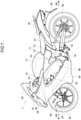
- Fig. 1 is a left side view of the saddle-ridden vehicle according to the present embodiment.
- an arrow FR indicates a vehicle front side
- an arrow RE indicates a vehicle rear side
- an arrow L indicates a vehicle left side
- an arrow R indicates a vehicle right side.
- a saddle-ridden vehicle 1 is configured by mounting various components such as an engine 16 and an electric system on a twin-spar vehicle body frame 10 formed by aluminum casting.
- the vehicle body frame 10 includes a pair of main frames 11 that branch from a head pipe (not shown) to left and right sides and extend to a rear side of the vehicle, and a pair of down frames (not shown) that branch from the head pipe to the left and right sides and extend downward.
- a rear portion of the engine 16 is supported by the pair of main frames 11, and a front portion of the engine 16 is supported by the pair of down frames.
- the engine 16 is supported by the vehicle body frame 10, so that rigidity of the entire vehicle is secured.
- Front portions of the main frames 11 serve as tank rails 12 located above the engine 16, and a fuel tank 17 is supported by the tank rails 12.
- Rear portions of the main frames 11 serve as body frames 13 located behind the engine 16, and swing arms 18 are swingably supported at substantially intermediate positions of the body frames 13 in an upper-lower direction.
- a seat rail (not shown) and a back stay (not shown) extend rearward from upper portions of the body frames 13.
- On the seat rail a rider seat 21 and a pillion seat 22 are supported behind the fuel tank 17.
- a pair of front forks 23 are steerably supported on the head pipe via a steering shaft (not shown).
- a front wheel 25 is rotatably supported by lower portions of the front forks 23, and an upper portion of the front wheel 25 is covered by a front fender 26.
- the swing arms 18 extend from the body frames 13 toward a rear side of the vehicle.
- a rear wheel 28 is rotatably supported by rear ends of the swing arms 18, and an upper side of the rear wheel 28 is covered by a rear fender 29.
- the engine 16 is coupled to the rear wheel 28 via a chain-drive transmission mechanism, and power is transmitted from the engine 16 to the rear wheel 28 via the transmission mechanism.
- Various cover members are attached to the vehicle body frame 10 of the saddle-ridden vehicle 1 as a vehicle body exterior.
- a front surface side of the vehicle front portion is covered by a front cowl 31, and a screen 33 is provided on an upper portion of the front cowl 31.
- a side surface side of the vehicle front portion is covered by a pair of side cowls 32.
- the front cowl 31, the screen 33, and the pair of side cowls 32 form a streamlined shape that reduces an air resistance received from the traveling wind on the vehicle front portion. Since these cover members cover a front side of the occupant and serve as a wind shield, hitting of the traveling wind on the occupant during traveling of the vehicle is fairly reduced.
- the front cowl 31, the screen 33, and the pair of side cowls 32 do not completely protect the occupant from the traveling wind.
- the traveling wind hits portions such as elbows, knees, thighs, and shins of the occupant that protrude from the pair of side cowls 32.
- an upper edge cover 42 and a rear edge cover 43 are provided on the side cowl 32, and the flow of the traveling wind along the outer surface of the side cowl 32 is diffused toward the outer side in the vehicle width direction to soften the hitting of the traveling wind on the occupant.
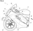
- Fig. 2 is a side view of the vehicle front portion according to the present embodiment.
- Fig. 3 is a top view of the vehicle front portion according to the present embodiment.
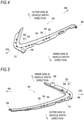
- Fig. 4 is a perspective view of the rear edge cover of the present embodiment when viewed from a front surface side.
- Fig. 5 is a perspective view of the rear edge cover of the present embodiment when viewed from a back surface side.
- Fig. 6 is a perspective view of a vicinity of a rear end of the side cowl according to the present embodiment.
- Fig. 7 is a cross-sectional view of a vicinity of a rear end of the rear edge cover according to the present embodiment.
- the screen 33 is provided on the upper portion of the front cowl 31, and the pair of side cowls 32 that cover sides of the front forks 23 are provided on a left edge and a right edge of the front cowl 31.
- the front cowl 31 is formed to cover a base end side of the screen 33 and a periphery of a central headlamp 34.
- Turn signal lamps 35 are provided between the front cowl 31 and the pair of side cowls 32.
- a streamlined shape is formed by drawing an upward-gradient curve from a front end of the headlamp 34 toward a rear end of the screen 33 and drawing a curve that widens a vehicle width from the front end of the headlamp 34 toward rear ends of the side cowls 32.
- a cowl main body 41 of the side cowl 32 extends from the front cowl 31 to a rear side of the vehicle.
- An upper edge of the cowl main body 41 is located in front of handlebars 19, and is inclined so as to draw a downward gradient toward the rear side of the vehicle when viewed in a vehicle side view.
- the upper edge cover 42 is provided on the upper edge of the cowl main body 41 along the upper edge.
- the upper edge cover 42 protrudes from an outer surface (a cowl outer surface) of the cowl main body 41, and directs the flow of the traveling wind along the outer surface of the cowl main body 41 toward the outer side in the vehicle width direction.
- the traveling wind is diffused in front of the handlebars 19 to soften the hitting of the traveling wind on the occupant.
- a side cover 36 is provided on a rear side of the vehicle of the side cowl 32.
- a rear edge of the cowl main body 41 is cut out so as to draw an arc when viewed in the vehicle side view, and an air discharge port is formed between the side cowl 32 and the side cover 36.
- the rear edge of the cowl main body 41 defines an opening edge of the air discharge port, and the rear edge cover 43 is provided along the rear edge.
- the rear edge cover 43 protrudes from the outer surface of the cowl main body 41, and directs the flow of the traveling wind along the outer surface of the cowl main body 41 toward the outer side in the vehicle width direction. The traveling wind is diffused in front of the air discharge port to soften the hitting of the traveling wind on the occupant.
- the upper edge cover 42 is provided at an upper edge of an upper portion of the cowl main body 41, the upper edge having a maximum vehicle width in a vehicle front-rear direction
- the rear edge cover 43 is provided at a rear edge of a lower portion of the cowl main body 41, the rear edge having the maximum vehicle width in the vehicle front-rear direction. Since the upper edge cover 42 and the rear edge cover 43 are provided at the portions where the vehicle width is maximized, the traveling wind is effectively diffused, and the hitting of the traveling wind on the occupant is further softened.
- the upper edge of the cowl main body 41 is reinforced by the upper edge cover 42, and the rear edge of the cowl main body 41 is reinforced by the rear edge cover 43.
- the air discharge port is provided with a louver member 37 that rectifies the traveling wind that has passed through an inner side of the side cowl 32. Since the side cowl 32 is coupled to the side cover 36 via the louver member 37, the rigidity of the side cowl 32 is increased.
- the rear edge cover 43 is curved so as to draw an arc when viewed in the vehicle side view.
- the rear edge cover 43 includes a flat-plate-shaped attachment portion 51 attached to the rear edge of the cowl main body 41 (see Fig. 6 ), and an elongated convex portion 52 that bulges outward in the vehicle width direction.
- a shallow groove 53 recessed inward in the vehicle width direction is formed at a boundary portion between the attachment portion 51 and the convex portion 52.
- a plurality of locking holes 54 and a plurality of positioning holes 55 are formed in the rear edge cover 43 along the shallow groove 53. Further, a plurality of fixing holes 56 are formed near both end positions and a bent position of the rear edge cover 43.
- a cross section of the convex portion 52 is formed in a V shape by a front side portion 57 that faces the front side of the vehicle and a rear side portion 58 that faces the rear side of the vehicle.
- the front side portion 57 of the convex portion 52 is inclined so as to widen the vehicle width toward the rear side of the vehicle, and the rear side portion 58 of the convex portion 52 extends inward in the vehicle width direction from a rear end of the front side portion 57 (see Fig. 7 ).
- the front side portion 57 is widened from both end positions of the rear edge cover 43 in a longitudinal direction toward the bent position, and the rear side portion 58 is widened from both ends of the rear edge cover 43 in the longitudinal direction toward the bent position. That is, the V-shaped cross section of the rear edge cover 43 at the bent position is the largest, and rigidity of the bent position is increased.
- the attachment portion 51 of the rear edge cover 43 is attached to an inner side of the rear edge of the cowl main body 41, and the convex portion 52 of the rear edge cover 43 is exposed along the rear edge of the cowl main body 41. Since the convex portion 52 of the rear edge cover 43 is curved when viewed in the vehicle side view, the rigidity of the side cowl 32 is increased and deformation is prevented. Further, a width of the front side portion 57 of the convex portion 52 in an inclination direction is formed to be larger than a width of the rear side portion 58 of the convex portion 52 in the vehicle width direction (particularly, see Fig. 7 ). Accordingly, a width of the convex portion 52 in a front-rear direction is increased when viewed in the vehicle side view, and particularly, rigidity of the side cowl 32 against bending in the front-rear direction is increased.
- the inner side in the vehicle width direction with respect to the outer surface of the cowl main body 41 indicates an inner side in the vehicle width direction with respect to an extension line L1 (see Fig. 7 ) obtained by extending the outer surface of the cowl main body 41.
- the outer side in the vehicle width direction with respect to the outer surface of the cowl main body 41 indicates an outer side in the vehicle width direction with respect to the extension line L1 obtained by extending the outer surface of the cowl main body 41.
- the concave portion 59 and the convex portion 52 are formed in a non-streamlined shape for the flow of the traveling wind along the outer surface of the cowl main body 41, and the traveling wind is easily separated from the outer surface of the cowl main body 41 at the concave portion 59 and the convex portion 52.
- a width of the inclined front side portion 57 of the convex portion 52 is large, the traveling wind hits the front side portion 57 and is repelled outward in the vehicle width direction to be easily separated.
- the rear side portion 58 is bent at an acute angle with respect to the front side portion 57 of the convex portion 52, the traveling wind is easily separated at the bent portion. When viewed in a vehicle top view, the traveling wind is separated so as to extend outward in the vehicle width direction toward the rear side of the vehicle, and the hitting of the traveling wind on the occupant is softened.
- the concave portion 59 is provided at the boundary between the cowl main body 41 and the convex portion 52, a height difference between the concave portion 59 and the convex portion 52 necessary for separating the traveling wind is secured.
- a protrusion amount of the convex portion 52 from the outer surface of the cowl main body 41 is reduced. Therefore, even when the rear edge cover 43 is provided on the cowl main body 41, an increase in a dimension of the saddle-ridden vehicle 1 (see Fig. 1 ) in the vehicle width direction is minimized. Since the protrusion amount of the convex portion 52 from the outer surface of the cowl main body 41 is small and the front side portion 57 of the convex portion 52 is inclined, an air resistance received by the convex portion 52 from the traveling wind is not fairly increased.
- the convex portion 52 When viewed in the vehicle side view, the convex portion 52 is curved so as to draw an arc in front of the vehicle, and an intermediate portion of the convex portion 52 in a longitudinal direction protrudes toward the front side of the vehicle.
- An upper half portion of the convex portion 52 is inclined at an upward gradient toward the rear side of the vehicle, and a lower half portion of the convex portion 52 is inclined at a downward gradient toward the rear side of the vehicle (see Fig. 2 ).
- the traveling wind easily flows along an extending direction of the convex portion 52, and the traveling wind is diffused in the upper-lower direction, so that the hitting of the traveling wind on the occupant is softened.
- the convex portion 52 When viewed in the vehicle side view, the convex portion 52 may be curved in a V shape with a top portion facing the front side of the vehicle.
- the upper edge cover 42 is formed in the same manner as the rear edge cover 43. That is, the rear edge cover 43 includes a flat-plate-shaped attachment portion and a V-shaped convex portion in a cross-sectional view.
- the upper edge cover 42 is attached to the rear edge of the cowl main body 41, and a step-shaped concave portion is formed at a boundary between the cowl main body 41 and a convex portion of the upper edge cover 42.
- the convex portion of the upper edge cover 42 is curved at a downward gradient toward the rear side of the vehicle. Accordingly, the upper edge cover 42 softens the hitting of the traveling wind on the occupant, and the air resistance of the upper edge cover 42 is prevented.
- the traveling wind is diffused in the vehicle width direction and the upper-lower direction by the rear edge cover 43 and the convex portion 52 of the upper edge cover 42.
- the cowl main body 41, the rear edge cover 43, and the upper edge cover 42 are separately formed, a degree of freedom in designing the shape and the protrusion amount of the convex portion 52 is improved, and the shape of the cowl main body 41 becomes simple and easy to form. Further, since colors of the cowl main body 41, the rear edge cover 43, and the upper edge cover 42 are changed, the side cowl 32 is accented and an appearance is improved.
- Figs. 8A to 8C are diagrams showing wind speed distributions of the traveling wind on outer surfaces of side cowls.
- Figs. 8A and 8B show a wind speed distribution of traveling wind on a side cowl of a comparative example
- Fig. 8C shows the wind speed distribution of the traveling wind on the side cowl of the present embodiment.
- a wind speed distribution of the traveling wind in the vicinity of the rear edge cover is shown, but a wind speed distribution of the traveling wind in the vicinity of the upper edge cover is also the same.
- a side cowl 61 of the comparative example is not provided with a rear edge cover.
- traveling wind F flows along an outer surface of the side cowl 61, and the flow of the traveling wind F is separated by a rear edge of the side cowl 61.
- the traveling wind F is separated from the rear edge of the side cowl 61, but a spreading width W1 of the traveling wind F does not increase.
- a wind speed rapidly increases, and there is a large difference between a wind speed in the vicinity of the outer surface of the side cowl 61 and a wind speed at a position far from the outer surface of the side cowl 61.
- the traveling wind F hits an elbow E of the occupant, a difference in a wind pressure received by an inner side and an outer side of the elbow E in the vehicle width direction becomes large, and the occupant is likely to feel uncomfortable.
- the traveling wind F separated from the side cowl 61 is not diffused, and the traveling wind F directly hits the elbow E of the occupant.
- the traveling wind F concentrates on the tip end of the elbow E, and the tip end of the elbow E receives a strong wind pressure. Therefore, since the elbow E locally receives the strong wind pressure, the traveling wind F hinders a handlebars operation by the occupant during high-speed traveling.
- the elbow E of the occupant receives the wind pressure is described, but other portions such as a knee, a thigh, and a shin that protrude from the side cowl 61 also strongly receive the wind pressure.
- the side cowl 32 of the present embodiment is provided with the rear edge cover 43 on the cowl main body 41.
- the traveling wind F flows along the outer surface of the cowl main body 41, and the flow of the traveling wind F is separated by the rear edge cover 43.
- the traveling wind F is diffused behind the rear edge cover 43, and a spreading width W2 of the traveling wind F increases. Since the wind speed gradually increases as the distance from the outer surface of the cowl main body 41 increases, there is no large difference between a wind speed in the vicinity of the outer surface of the cowl main body 41 and a wind speed at a position far from the outer surface of the cowl main body 41.
- the traveling wind F hits the elbow E of the occupant, the difference in the wind pressure received by the inner side and the outer side of the elbow E in the vehicle width direction becomes small, and the occupant is less likely to feel uncomfortable. That is, the occupant does not locally receive a strong wind pressure, and the traveling wind does not hinder the handlebars operation.
- the flow of the traveling wind F along the outer surface of the side cowl 32 is separated by the rear edge cover 43 and the upper edge cover 42. Since the traveling wind F is diffused outward in the vehicle width direction behind the rear edge cover 43 and the upper edge cover 42, the hitting of the traveling wind F on a portion of the occupant that protrudes from the side cowl 32 is softened. The air resistance is reduced by the side cowl 32, traveling is stabilized, the strong local wind pressure on the occupant is prevented, and comfort during driving is not impaired.
- the rear edge cover is provided at a portion of the cowl main body where the vehicle width is maximized in the vehicle front-rear direction, but the rear edge cover may be provided at another portion.
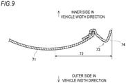
- a narrow region 72 where a vehicle width narrows toward a rear side of a vehicle may be formed on an outer surface of a cowl main body 71, and a rear edge cover 73 may be provided in the narrow region 72.
- the rear edge cover 73 may be provided at the rear side of the narrow region 72.
- an upper edge cover may be provided in the narrow region or at the rear side of the narrow region.
- the rear edge cover and the upper edge cover are provided on the cowl main body, and the convex portions are formed on the rear edge cover and the upper edge cover, but the convex portion may be formed on the cowl main body. Accordingly, the number of components can be reduced.
- both the rear edge cover and the upper edge cover are provided on the cowl main body, but any one of the rear edge cover and the upper edge cover may be provided on the cowl main body.
- the cross sections of the convex portions of the rear edge cover and the upper edge cover are formed in the V shape, but the cross-sectional shapes of the convex portions are not particularly limited.
- the convex portions may be formed so as to protrude outward in the vehicle width direction from the outer surface of the cowl main body.
- the convex portion is formed on the rear edge cover of the rear edge of the cowl main body, and the convex portion is formed on the upper edge cover of the upper edge of the cowl main body, but the convex portions may be provided on a downstream side of the traveling wind that flows on the outer surface of the side cowl.
- the convex portions of the rear edge cover and the upper edge cover are curved so as to draw an arc when viewed in the vehicle side view, but the convex portions may be formed linearly.
- the concave portion is formed at the boundary between the cowl main body and the rear edge cover, but the concave portion may not be formed at the boundary between the cowl main body and the rear edge cover. Similarly, the concave portion may not be formed at the boundary between the cowl main body and the upper edge cover. Even with such a configuration, it is possible to soften the hitting of the traveling wind on the portion of the occupant that protrudes from the side cowl.
- the side cowl of the saddle-ridden vehicle of the present embodiment is not limited to a motorcycle of a tourer type, and may be adopted in a motorcycle of another type. Further, the saddle-ridden vehicle is not limited to all vehicles where the occupant rides in a posture of straddling a seat, and also includes a vehicle of a scooter type where the occupant rides without straddling a seat.
- the side cowl (32) of the present embodiment is the side cowl that covers the vehicle side portion of the saddle-ridden vehicle (1), and the convex portion (52) that elongates in the upper-lower direction and protrudes outward in the vehicle width direction with respect to the cowl outer surface is formed on the downstream side of the traveling wind that flows on the cowl outer surface.
- the flow of the traveling wind along the cowl outer surface is separated by the convex portion. Since the traveling wind is diffused behind the convex portion, the hitting of the traveling wind on the portion of the occupant that protrudes from the side cowl is softened. The air resistance is reduced by the side cowl, traveling is stabilized, the strong local wind pressure on the occupant is prevented, and comfort during driving is not impaired.
- the convex portion is formed at a portion of the cowl outer surface where the vehicle width is maximized in the vehicle front-rear direction. According to this configuration, the flow of the traveling wind can be separated by the convex portion at the most easily separable portion of the cowl outer surface.
- the cowl outer surface includes the narrow region (72) where the vehicle width narrows toward the rear side of the vehicle, and the convex portion is formed in the narrow region or at the rear side of the narrow region. According to this configuration, the vehicle width can be suppressed even when the protrusion amount of the convex portion is increased, and the flow of the traveling wind along the cowl outer surface is more easily separated by the convex portion that fairly protrudes from the cowl outer surface.
- the concave portion (59) recessed inward in the vehicle width direction is formed at the boundary between the cowl outer surface and the convex portion. According to this configuration, the flow of the traveling wind along the cowl outer surface is more easily separated by the concave portion and the convex portion.
- the convex portion is curved when viewed in the vehicle side view. According to this configuration, the rigidity of the side cowl is increased by the curved convex portion, and deformation of the side cowl is prevented.
- the intermediate portion of the convex portion in the longitudinal direction is curved so as to protrude toward the front side of the vehicle. According to this configuration, the traveling wind is diffused in the upper-lower direction along the convex portion, and the hitting of the traveling wind on the occupant is softened.
- the rear edge of the cowl outer surface defines the opening edge of the air discharge port, and the convex portion is formed along the rear edge of the cowl outer surface. According to this configuration, the traveling wind is diffused in front of the air discharge port, and the hitting of the traveling wind on the occupant is softened. Since the convex portion is provided along the opening edge of the air discharge port that is relatively likely to vibrate, the rigidity of the side cowl is increased, and deflection is prevented.
- an upper edge of the cowl outer surface is located in front of the handlebars (19), and the convex portion is formed along the upper edge of the cowl outer surface. According to this configuration, the traveling wind is diffused in front of the handlebars, and the hitting of the running wind on the occupant is softened.
- the cross section of the convex portion is formed in the V shape by the front side portion (57) facing the front side of the vehicle and the rear side portion (58) facing the rear side of the vehicle. According to this configuration, the rigidity of the side cowl is increased by the V-shaped cross section of the convex portion, and deformation of the side cowl is prevented.
- the front side portion is inclined so as to widen the vehicle width toward the rear side of the vehicle, the rear side extends inward in the vehicle width direction from the rear end of the front side portion, and the width of the front side portion in the inclination direction is larger than the width of the rear side portion in the vehicle width direction.
- the width of the front side portion of the convex portion is formed to be wide, so that the width of the convex portion in a front-rear direction is increased when viewed in the vehicle side view, and particularly, the rigidity against deformation of the side cowl in the front-rear direction is increased.
Landscapes
- Engineering & Computer Science (AREA)
- Mechanical Engineering (AREA)
- Body Structure For Vehicles (AREA)
Abstract
Description
- The present invention relates to a side cowl.
- As a saddle-ridden vehicle such as a motorcycle, a vehicle is known in which a vehicle front portion is covered by a front cowl and a vehicle side portion is covered by a side cowl (for example, see Patent Literature 1). A streamline-shaped front cowl and streamline-shaped side cowls are integrally attached to a saddle-ridden vehicle described in
Patent Literature 1, and traveling wind flows from a front side of the vehicle to a rear side of the vehicle along outer surfaces of the front cowl and the side cowls. Because of a windbreak effect of the front cowl and the side cowls, an air resistance received by the vehicle from the traveling wind is reduced so that stable traveling is enabled, and hitting of the traveling wind on an occupant is reduced so that comfortable driving of the saddle-ridden vehicle is implemented. - Patent Literature 1:
JP-A-2005-178621 - Although the front cowl and the side cowls described in
Patent Literature 1 weaken the hitting of the traveling wind on the occupant, further comfort is required when driving the saddle-ridden vehicle. Particularly, there is a problem that the traveling wind strongly hits a portion of the occupant that protrudes from the side cowl, and comfort when driving the saddle-ridden vehicle is reduced. - The present invention has been made in view of the above circumstances, and an object thereof is to provide a side cowl that can improve comfort during driving while reducing an air resistance due to traveling wind.
- According to one advantageous aspect of the present invention, there is provided a side cowl configured to cover a vehicle side portion of a saddle-ridden vehicle, including:
a convex portion, elongating in an upper-lower direction, protruding outward in a vehicle width direction with respect to a cowl outer surface, and formed on the cowl outer surface at a downstream side of traveling wind that flows on the cowl outer surface. - According to a side cowl of one aspect of the present invention, a flow of traveling wind along a cowl outer surface is separated by a convex portion. Since the traveling wind is diffused outward in a vehicle width direction at a rear aide of the convex portion, hitting of the traveling wind on a portion of an occupant that protrudes from the side cowl is softened. An air resistance is reduced by the side cowl, traveling is stabilized, a strong local wind pressure on the occupant is prevented, and comfort during driving is not impaired.
-
-
Fig. 1 is a left side view of a saddle-ridden vehicle according to the present embodiment. -
Fig. 2 is a side view of a vehicle front portion according to the present embodiment. -
Fig. 3 is a top view of the vehicle front portion according to the present embodiment. -
Fig. 4 is a perspective view of a rear edge cover of the present embodiment when viewed from a front surface side. -
Fig. 5 is a perspective view of the rear edge cover of the present embodiment when viewed from a back surface side. -
Fig. 6 is a perspective view of a vicinity of a rear end of a side cowl according to the present embodiment. -
Fig. 7 is a cross-sectional view of a vicinity of a rear end of the rear edge cover according to the present embodiment. -
Figs. 8A to 8C are diagrams showing wind speed distributions of traveling wind on outer surfaces of side cowls. -
Fig. 9 is a cross-sectional view of a vicinity of a rear end of a rear edge cover according to a modification. - A side cowl according to one aspect of the present invention covers a vehicle side portion of a saddle-ridden vehicle, and traveling wind flows along a cowl outer surface. A convex portion that elongates in an upper-lower direction and protrudes outward in a vehicle width direction with respect to the cowl outer surface is formed on a downstream side of the traveling wind on the cowl outer surface, and a flow of the traveling wind along the cowl outer surface is separated by the convex portion. Since the traveling wind is diffused outward in the vehicle width direction at the rear side of the convex portion, hitting of the traveling wind on a portion of an occupant that protrudes from the side cowl is softened. An air resistance is reduced by the side cowl, traveling is stabilized, a strong local wind pressure on the occupant is prevented, and comfort during driving is not impaired.
- Hereinafter, the present embodiment will be described in detail with reference to the accompanying drawings.
Fig. 1 is a left side view of the saddle-ridden vehicle according to the present embodiment. Further, in the following drawings, an arrow FR indicates a vehicle front side, an arrow RE indicates a vehicle rear side, an arrow L indicates a vehicle left side, and an arrow R indicates a vehicle right side. - As shown in
Fig. 1 , a saddle-riddenvehicle 1 is configured by mounting various components such as anengine 16 and an electric system on a twin-sparvehicle body frame 10 formed by aluminum casting. Thevehicle body frame 10 includes a pair ofmain frames 11 that branch from a head pipe (not shown) to left and right sides and extend to a rear side of the vehicle, and a pair of down frames (not shown) that branch from the head pipe to the left and right sides and extend downward. A rear portion of theengine 16 is supported by the pair ofmain frames 11, and a front portion of theengine 16 is supported by the pair of down frames. Theengine 16 is supported by thevehicle body frame 10, so that rigidity of the entire vehicle is secured. - Front portions of the
main frames 11 serve astank rails 12 located above theengine 16, and afuel tank 17 is supported by thetank rails 12. Rear portions of themain frames 11 serve asbody frames 13 located behind theengine 16, andswing arms 18 are swingably supported at substantially intermediate positions of thebody frames 13 in an upper-lower direction. A seat rail (not shown) and a back stay (not shown) extend rearward from upper portions of thebody frames 13. On the seat rail, arider seat 21 and apillion seat 22 are supported behind thefuel tank 17. - A pair of
front forks 23 are steerably supported on the head pipe via a steering shaft (not shown). Afront wheel 25 is rotatably supported by lower portions of thefront forks 23, and an upper portion of thefront wheel 25 is covered by afront fender 26. Theswing arms 18 extend from thebody frames 13 toward a rear side of the vehicle. Arear wheel 28 is rotatably supported by rear ends of theswing arms 18, and an upper side of therear wheel 28 is covered by arear fender 29. Theengine 16 is coupled to therear wheel 28 via a chain-drive transmission mechanism, and power is transmitted from theengine 16 to therear wheel 28 via the transmission mechanism. - Various cover members are attached to the
vehicle body frame 10 of the saddle-riddenvehicle 1 as a vehicle body exterior. For example, a front surface side of the vehicle front portion is covered by afront cowl 31, and ascreen 33 is provided on an upper portion of thefront cowl 31. Further, a side surface side of the vehicle front portion is covered by a pair ofside cowls 32. Thefront cowl 31, thescreen 33, and the pair ofside cowls 32 form a streamlined shape that reduces an air resistance received from the traveling wind on the vehicle front portion. Since these cover members cover a front side of the occupant and serve as a wind shield, hitting of the traveling wind on the occupant during traveling of the vehicle is fairly reduced. - However, the
front cowl 31, thescreen 33, and the pair ofside cowls 32 do not completely protect the occupant from the traveling wind. For example, the traveling wind hits portions such as elbows, knees, thighs, and shins of the occupant that protrude from the pair ofside cowls 32. As a distance from vicinities of outer surfaces of theside cowls 32 increases, the traveling wind becomes strong, and the occupant is likely to feel uncomfortable due to a strong local wind pressure. Therefore, in the present embodiment, anupper edge cover 42 and arear edge cover 43 are provided on theside cowl 32, and the flow of the traveling wind along the outer surface of theside cowl 32 is diffused toward the outer side in the vehicle width direction to soften the hitting of the traveling wind on the occupant. - Hereinafter, the side cowls of the saddle-ridden vehicle will be described with reference to
Figs. 2 to 7 .Fig. 2 is a side view of the vehicle front portion according to the present embodiment.Fig. 3 is a top view of the vehicle front portion according to the present embodiment.Fig. 4 is a perspective view of the rear edge cover of the present embodiment when viewed from a front surface side.Fig. 5 is a perspective view of the rear edge cover of the present embodiment when viewed from a back surface side.Fig. 6 is a perspective view of a vicinity of a rear end of the side cowl according to the present embodiment.Fig. 7 is a cross-sectional view of a vicinity of a rear end of the rear edge cover according to the present embodiment. - As shown in
Figs. 2 and3 , thescreen 33 is provided on the upper portion of thefront cowl 31, and the pair ofside cowls 32 that cover sides of thefront forks 23 are provided on a left edge and a right edge of thefront cowl 31. Thefront cowl 31 is formed to cover a base end side of thescreen 33 and a periphery of acentral headlamp 34.Turn signal lamps 35 are provided between thefront cowl 31 and the pair of side cowls 32. A streamlined shape is formed by drawing an upward-gradient curve from a front end of theheadlamp 34 toward a rear end of thescreen 33 and drawing a curve that widens a vehicle width from the front end of theheadlamp 34 toward rear ends of the side cowls 32. - A cowl
main body 41 of theside cowl 32 extends from thefront cowl 31 to a rear side of the vehicle. An upper edge of the cowlmain body 41 is located in front ofhandlebars 19, and is inclined so as to draw a downward gradient toward the rear side of the vehicle when viewed in a vehicle side view. Theupper edge cover 42 is provided on the upper edge of the cowlmain body 41 along the upper edge. Theupper edge cover 42 protrudes from an outer surface (a cowl outer surface) of the cowlmain body 41, and directs the flow of the traveling wind along the outer surface of the cowlmain body 41 toward the outer side in the vehicle width direction. The traveling wind is diffused in front of thehandlebars 19 to soften the hitting of the traveling wind on the occupant. - A
side cover 36 is provided on a rear side of the vehicle of theside cowl 32. A rear edge of the cowlmain body 41 is cut out so as to draw an arc when viewed in the vehicle side view, and an air discharge port is formed between theside cowl 32 and theside cover 36. The rear edge of the cowlmain body 41 defines an opening edge of the air discharge port, and therear edge cover 43 is provided along the rear edge. Therear edge cover 43 protrudes from the outer surface of the cowlmain body 41, and directs the flow of the traveling wind along the outer surface of the cowlmain body 41 toward the outer side in the vehicle width direction. The traveling wind is diffused in front of the air discharge port to soften the hitting of the traveling wind on the occupant. - When the traveling wind flows from a front side to a rear side along the outer surface of the cowl
main body 41, the traveling wind is most likely to be separated at a portion where the vehicle width is maximized. Therefore, theupper edge cover 42 is provided at an upper edge of an upper portion of the cowlmain body 41, the upper edge having a maximum vehicle width in a vehicle front-rear direction, and therear edge cover 43 is provided at a rear edge of a lower portion of the cowlmain body 41, the rear edge having the maximum vehicle width in the vehicle front-rear direction. Since theupper edge cover 42 and therear edge cover 43 are provided at the portions where the vehicle width is maximized, the traveling wind is effectively diffused, and the hitting of the traveling wind on the occupant is further softened. - The upper edge of the cowl
main body 41 is reinforced by theupper edge cover 42, and the rear edge of the cowlmain body 41 is reinforced by therear edge cover 43. Particularly, since therear edge cover 43 is provided along the opening edge of the air discharge port, rigidity of which is likely to be reduced by exhaust air heat, rigidity of theside cowl 32 is increased, and vibration and deflection are effectively prevented. Further, the air discharge port is provided with alouver member 37 that rectifies the traveling wind that has passed through an inner side of theside cowl 32. Since theside cowl 32 is coupled to theside cover 36 via thelouver member 37, the rigidity of theside cowl 32 is increased. - As shown in
Figs. 4 and 5 , therear edge cover 43 is curved so as to draw an arc when viewed in the vehicle side view. Therear edge cover 43 includes a flat-plate-shapedattachment portion 51 attached to the rear edge of the cowl main body 41 (seeFig. 6 ), and an elongatedconvex portion 52 that bulges outward in the vehicle width direction. Ashallow groove 53 recessed inward in the vehicle width direction is formed at a boundary portion between theattachment portion 51 and theconvex portion 52. A plurality of lockingholes 54 and a plurality of positioning holes 55 are formed in therear edge cover 43 along theshallow groove 53. Further, a plurality of fixingholes 56 are formed near both end positions and a bent position of therear edge cover 43. - A cross section of the
convex portion 52 is formed in a V shape by afront side portion 57 that faces the front side of the vehicle and arear side portion 58 that faces the rear side of the vehicle. Thefront side portion 57 of theconvex portion 52 is inclined so as to widen the vehicle width toward the rear side of the vehicle, and therear side portion 58 of theconvex portion 52 extends inward in the vehicle width direction from a rear end of the front side portion 57 (seeFig. 7 ). Thefront side portion 57 is widened from both end positions of therear edge cover 43 in a longitudinal direction toward the bent position, and therear side portion 58 is widened from both ends of therear edge cover 43 in the longitudinal direction toward the bent position. That is, the V-shaped cross section of therear edge cover 43 at the bent position is the largest, and rigidity of the bent position is increased. - As shown in
Figs. 6 and7 , theattachment portion 51 of therear edge cover 43 is attached to an inner side of the rear edge of the cowlmain body 41, and theconvex portion 52 of therear edge cover 43 is exposed along the rear edge of the cowlmain body 41. Since theconvex portion 52 of therear edge cover 43 is curved when viewed in the vehicle side view, the rigidity of theside cowl 32 is increased and deformation is prevented. Further, a width of thefront side portion 57 of theconvex portion 52 in an inclination direction is formed to be larger than a width of therear side portion 58 of theconvex portion 52 in the vehicle width direction (particularly, seeFig. 7 ). Accordingly, a width of theconvex portion 52 in a front-rear direction is increased when viewed in the vehicle side view, and particularly, rigidity of theside cowl 32 against bending in the front-rear direction is increased. - A front edge of the
front side portion 57 of theconvex portion 52 enters an inner side in the vehicle width direction with respect to the outer surface of the cowlmain body 41, and a rear edge of thefront side portion 57 of theconvex portion 52 protrudes outward in the vehicle width direction with respect to the outer surface of the cowlmain body 41. Therefore, a step-shapedconcave portion 59 recessed inward in the vehicle width direction is formed at a boundary between theconvex portion 52 and the cowlmain body 41. The inner side in the vehicle width direction with respect to the outer surface of the cowlmain body 41 indicates an inner side in the vehicle width direction with respect to an extension line L1 (seeFig. 7 ) obtained by extending the outer surface of the cowlmain body 41. The outer side in the vehicle width direction with respect to the outer surface of the cowlmain body 41 indicates an outer side in the vehicle width direction with respect to the extension line L1 obtained by extending the outer surface of the cowlmain body 41. - The
concave portion 59 and theconvex portion 52 are formed in a non-streamlined shape for the flow of the traveling wind along the outer surface of the cowlmain body 41, and the traveling wind is easily separated from the outer surface of the cowlmain body 41 at theconcave portion 59 and theconvex portion 52. Particularly, since a width of the inclinedfront side portion 57 of theconvex portion 52 is large, the traveling wind hits thefront side portion 57 and is repelled outward in the vehicle width direction to be easily separated. Further, since therear side portion 58 is bent at an acute angle with respect to thefront side portion 57 of theconvex portion 52, the traveling wind is easily separated at the bent portion. When viewed in a vehicle top view, the traveling wind is separated so as to extend outward in the vehicle width direction toward the rear side of the vehicle, and the hitting of the traveling wind on the occupant is softened. - Since the
concave portion 59 is provided at the boundary between the cowlmain body 41 and theconvex portion 52, a height difference between theconcave portion 59 and theconvex portion 52 necessary for separating the traveling wind is secured. As compared with a configuration in which a height difference necessary for separating the traveling wind is secured only by theconvex portion 52 without providing theconcave portion 59, a protrusion amount of theconvex portion 52 from the outer surface of the cowlmain body 41 is reduced. Therefore, even when therear edge cover 43 is provided on the cowlmain body 41, an increase in a dimension of the saddle-ridden vehicle 1 (seeFig. 1 ) in the vehicle width direction is minimized. Since the protrusion amount of theconvex portion 52 from the outer surface of the cowlmain body 41 is small and thefront side portion 57 of theconvex portion 52 is inclined, an air resistance received by theconvex portion 52 from the traveling wind is not fairly increased. - When viewed in the vehicle side view, the
convex portion 52 is curved so as to draw an arc in front of the vehicle, and an intermediate portion of theconvex portion 52 in a longitudinal direction protrudes toward the front side of the vehicle. An upper half portion of theconvex portion 52 is inclined at an upward gradient toward the rear side of the vehicle, and a lower half portion of theconvex portion 52 is inclined at a downward gradient toward the rear side of the vehicle (seeFig. 2 ). The traveling wind easily flows along an extending direction of theconvex portion 52, and the traveling wind is diffused in the upper-lower direction, so that the hitting of the traveling wind on the occupant is softened. The traveling wind that hits theconvex portion 52 escapes obliquely upward and obliquely downward, so that the air resistance received by theconvex portion 52 from the traveling wind is reduced. When viewed in the vehicle side view, theconvex portion 52 may be curved in a V shape with a top portion facing the front side of the vehicle. - Although not shown, the
upper edge cover 42 is formed in the same manner as therear edge cover 43. That is, therear edge cover 43 includes a flat-plate-shaped attachment portion and a V-shaped convex portion in a cross-sectional view. Theupper edge cover 42 is attached to the rear edge of the cowlmain body 41, and a step-shaped concave portion is formed at a boundary between the cowlmain body 41 and a convex portion of theupper edge cover 42. The convex portion of theupper edge cover 42 is curved at a downward gradient toward the rear side of the vehicle. Accordingly, theupper edge cover 42 softens the hitting of the traveling wind on the occupant, and the air resistance of theupper edge cover 42 is prevented. - Since the
rear edge cover 43 and theupper edge cover 42 are attached to the cowlmain body 41 in this way, the traveling wind is diffused in the vehicle width direction and the upper-lower direction by therear edge cover 43 and theconvex portion 52 of theupper edge cover 42. Since the cowlmain body 41, therear edge cover 43, and theupper edge cover 42 are separately formed, a degree of freedom in designing the shape and the protrusion amount of theconvex portion 52 is improved, and the shape of the cowlmain body 41 becomes simple and easy to form. Further, since colors of the cowlmain body 41, therear edge cover 43, and theupper edge cover 42 are changed, theside cowl 32 is accented and an appearance is improved. - The flow of the traveling wind on the outer surface of the side cowl will be described with reference to
Figs. 8A to 8C. Figs. 8A to 8C are diagrams showing wind speed distributions of the traveling wind on outer surfaces of side cowls.Figs. 8A and 8B show a wind speed distribution of traveling wind on a side cowl of a comparative example, andFig. 8C shows the wind speed distribution of the traveling wind on the side cowl of the present embodiment. Here, a wind speed distribution of the traveling wind in the vicinity of the rear edge cover is shown, but a wind speed distribution of the traveling wind in the vicinity of the upper edge cover is also the same. - As shown in
Fig. 8A , aside cowl 61 of the comparative example is not provided with a rear edge cover. When the vehicle travels, traveling wind F flows along an outer surface of theside cowl 61, and the flow of the traveling wind F is separated by a rear edge of theside cowl 61. The traveling wind F is separated from the rear edge of theside cowl 61, but a spreading width W1 of the traveling wind F does not increase. As a distance from the outer surface of theside cowl 61 increases, a wind speed rapidly increases, and there is a large difference between a wind speed in the vicinity of the outer surface of theside cowl 61 and a wind speed at a position far from the outer surface of theside cowl 61. When the traveling wind F hits an elbow E of the occupant, a difference in a wind pressure received by an inner side and an outer side of the elbow E in the vehicle width direction becomes large, and the occupant is likely to feel uncomfortable. - in this way, the traveling wind F separated from the
side cowl 61 is not diffused, and the traveling wind F directly hits the elbow E of the occupant. Particularly, as shown inFig. 8B , when a boundary of the traveling wind F coincides with a tip end of the elbow E, the traveling wind F concentrates on the tip end of the elbow E, and the tip end of the elbow E receives a strong wind pressure. Therefore, since the elbow E locally receives the strong wind pressure, the traveling wind F hinders a handlebars operation by the occupant during high-speed traveling. Here, an example in which the elbow E of the occupant receives the wind pressure is described, but other portions such as a knee, a thigh, and a shin that protrude from theside cowl 61 also strongly receive the wind pressure. - On the contrary, as shown in
Fig. 8C , theside cowl 32 of the present embodiment is provided with therear edge cover 43 on the cowlmain body 41. When the vehicle travels, the traveling wind F flows along the outer surface of the cowlmain body 41, and the flow of the traveling wind F is separated by therear edge cover 43. The traveling wind F is diffused behind therear edge cover 43, and a spreading width W2 of the traveling wind F increases. Since the wind speed gradually increases as the distance from the outer surface of the cowlmain body 41 increases, there is no large difference between a wind speed in the vicinity of the outer surface of the cowlmain body 41 and a wind speed at a position far from the outer surface of the cowlmain body 41. When the traveling wind F hits the elbow E of the occupant, the difference in the wind pressure received by the inner side and the outer side of the elbow E in the vehicle width direction becomes small, and the occupant is less likely to feel uncomfortable. That is, the occupant does not locally receive a strong wind pressure, and the traveling wind does not hinder the handlebars operation. - As described above, according to the present embodiment, the flow of the traveling wind F along the outer surface of the
side cowl 32 is separated by therear edge cover 43 and theupper edge cover 42. Since the traveling wind F is diffused outward in the vehicle width direction behind therear edge cover 43 and theupper edge cover 42, the hitting of the traveling wind F on a portion of the occupant that protrudes from theside cowl 32 is softened. The air resistance is reduced by theside cowl 32, traveling is stabilized, the strong local wind pressure on the occupant is prevented, and comfort during driving is not impaired. - In the present embodiment, the rear edge cover is provided at a portion of the cowl main body where the vehicle width is maximized in the vehicle front-rear direction, but the rear edge cover may be provided at another portion. For example, as shown in
Fig. 9 , anarrow region 72 where a vehicle width narrows toward a rear side of a vehicle may be formed on an outer surface of a cowlmain body 71, and arear edge cover 73 may be provided in thenarrow region 72. Therear edge cover 73 may be provided at the rear side of thenarrow region 72. Accordingly, even when a protrusion amount of aconvex portion 74 of therear edge cover 73 is increased, the vehicle width can be suppressed, and the flow of the traveling wind is more easily separated by theconvex portion 74 that fairly protrudes from the outer surface of the cowlmain body 71. Similarly, an upper edge cover may be provided in the narrow region or at the rear side of the narrow region. - In the present embodiment, the rear edge cover and the upper edge cover are provided on the cowl main body, and the convex portions are formed on the rear edge cover and the upper edge cover, but the convex portion may be formed on the cowl main body. Accordingly, the number of components can be reduced.
- In the present embodiment, both the rear edge cover and the upper edge cover are provided on the cowl main body, but any one of the rear edge cover and the upper edge cover may be provided on the cowl main body.
- In the present embodiment, the cross sections of the convex portions of the rear edge cover and the upper edge cover are formed in the V shape, but the cross-sectional shapes of the convex portions are not particularly limited. The convex portions may be formed so as to protrude outward in the vehicle width direction from the outer surface of the cowl main body.
- In the present embodiment, the convex portion is formed on the rear edge cover of the rear edge of the cowl main body, and the convex portion is formed on the upper edge cover of the upper edge of the cowl main body, but the convex portions may be provided on a downstream side of the traveling wind that flows on the outer surface of the side cowl.
- In the present embodiment, the convex portions of the rear edge cover and the upper edge cover are curved so as to draw an arc when viewed in the vehicle side view, but the convex portions may be formed linearly.
- In the present embodiment, the concave portion is formed at the boundary between the cowl main body and the rear edge cover, but the concave portion may not be formed at the boundary between the cowl main body and the rear edge cover. Similarly, the concave portion may not be formed at the boundary between the cowl main body and the upper edge cover. Even with such a configuration, it is possible to soften the hitting of the traveling wind on the portion of the occupant that protrudes from the side cowl.
- The side cowl of the saddle-ridden vehicle of the present embodiment is not limited to a motorcycle of a tourer type, and may be adopted in a motorcycle of another type. Further, the saddle-ridden vehicle is not limited to all vehicles where the occupant rides in a posture of straddling a seat, and also includes a vehicle of a scooter type where the occupant rides without straddling a seat.
- As described above, the side cowl (32) of the present embodiment is the side cowl that covers the vehicle side portion of the saddle-ridden vehicle (1), and the convex portion (52) that elongates in the upper-lower direction and protrudes outward in the vehicle width direction with respect to the cowl outer surface is formed on the downstream side of the traveling wind that flows on the cowl outer surface. According to this configuration, the flow of the traveling wind along the cowl outer surface is separated by the convex portion. Since the traveling wind is diffused behind the convex portion, the hitting of the traveling wind on the portion of the occupant that protrudes from the side cowl is softened. The air resistance is reduced by the side cowl, traveling is stabilized, the strong local wind pressure on the occupant is prevented, and comfort during driving is not impaired.
- In the side cowl of the present embodiment, the convex portion is formed at a portion of the cowl outer surface where the vehicle width is maximized in the vehicle front-rear direction. According to this configuration, the flow of the traveling wind can be separated by the convex portion at the most easily separable portion of the cowl outer surface.
- In the side cowl of the present embodiment, the cowl outer surface includes the narrow region (72) where the vehicle width narrows toward the rear side of the vehicle, and the convex portion is formed in the narrow region or at the rear side of the narrow region. According to this configuration, the vehicle width can be suppressed even when the protrusion amount of the convex portion is increased, and the flow of the traveling wind along the cowl outer surface is more easily separated by the convex portion that fairly protrudes from the cowl outer surface.
- In the side cowl of the present embodiment, the concave portion (59) recessed inward in the vehicle width direction is formed at the boundary between the cowl outer surface and the convex portion. According to this configuration, the flow of the traveling wind along the cowl outer surface is more easily separated by the concave portion and the convex portion.
- In the side cowl of the present embodiment, the convex portion is curved when viewed in the vehicle side view. According to this configuration, the rigidity of the side cowl is increased by the curved convex portion, and deformation of the side cowl is prevented.
- In the side cowl of the present embodiment, when viewed in the vehicle side view, the intermediate portion of the convex portion in the longitudinal direction is curved so as to protrude toward the front side of the vehicle. According to this configuration, the traveling wind is diffused in the upper-lower direction along the convex portion, and the hitting of the traveling wind on the occupant is softened.
- In the side cowl of the present embodiment, the rear edge of the cowl outer surface defines the opening edge of the air discharge port, and the convex portion is formed along the rear edge of the cowl outer surface. According to this configuration, the traveling wind is diffused in front of the air discharge port, and the hitting of the traveling wind on the occupant is softened. Since the convex portion is provided along the opening edge of the air discharge port that is relatively likely to vibrate, the rigidity of the side cowl is increased, and deflection is prevented.
- In the side cowl of the present embodiment, an upper edge of the cowl outer surface is located in front of the handlebars (19), and the convex portion is formed along the upper edge of the cowl outer surface. According to this configuration, the traveling wind is diffused in front of the handlebars, and the hitting of the running wind on the occupant is softened.
- In the side cowl of the present embodiment, the cross section of the convex portion is formed in the V shape by the front side portion (57) facing the front side of the vehicle and the rear side portion (58) facing the rear side of the vehicle. According to this configuration, the rigidity of the side cowl is increased by the V-shaped cross section of the convex portion, and deformation of the side cowl is prevented.
- In the side cowl of the present embodiment, the front side portion is inclined so as to widen the vehicle width toward the rear side of the vehicle, the rear side extends inward in the vehicle width direction from the rear end of the front side portion, and the width of the front side portion in the inclination direction is larger than the width of the rear side portion in the vehicle width direction. According to this configuration, the width of the front side portion of the convex portion is formed to be wide, so that the width of the convex portion in a front-rear direction is increased when viewed in the vehicle side view, and particularly, the rigidity against deformation of the side cowl in the front-rear direction is increased.
- Although the present embodiment has been described, the above-described embodiment and modifications may be combined entirely or partially as another embodiment.
- The technique of the present invention is not limited to the above-described embodiment, and various changes, substitutions, and modifications may be made without departing from the spirit of the technical concept of the present invention. Further, the present invention may be implemented using other methods as long as the technical concept can be implemented by the methods through advance of the technology or other derivative technology. Therefore, the claims cover all embodiments that may be included within the scope of the technical concept.
Claims (10)
- A side cowl (32) configured to cover a vehicle side portion of a saddle-ridden vehicle, characterized by comprising:
a convex portion (52, 74), elongating in an upper-lower direction, protruding outward in a vehicle width direction with respect to a cowl outer surface, and formed on the cowl outer surface at a downstream side of traveling wind that flows on the cowl outer surface. - The side cowl (32) according to claim 1, wherein
the convex portion (52) is formed at a portion of the cowl outer surface where a vehicle width is maximized in a vehicle front-rear direction. - The side cowl (32) according to claim 1, whereinthe cowl outer surface includes a narrow region (72) where a vehicle width narrows toward a rear side of a vehicle, andthe convex portion (74) is formed in the narrow region (72) or at a rear side of the narrow region (72).
- The side cowl (32) according to any one of claims 1 to 3, wherein
a concave portion (59) recessed inward in a vehicle width direction is formed at a boundary between the cowl outer surface and the convex portion (52, 74). - The side cowl (32) according to any one of claims 1 to 4, wherein
the convex portion (52, 74) is curved when viewed in a vehicle side view. - The side cowl (32) according to claim 5, wherein
when viewed in a vehicle side view, an intermediate portion of the convex portion in a longitudinal direction is curved so as to protrude toward a front side of a vehicle. - The side cowl (32) according to any one of claims 1 to 6, whereina rear edge of the cowl outer surface defines as an opening edge of an air discharge port, andthe convex portion (52, 74) is formed along the rear edge of the cowl outer surface.
- The side cowl (32) according to any one of claims 1 to 7, whereinan upper edge of the cowl outer surface is located in front of handlebars (19), andthe convex portion (52, 74) is formed along the upper edge of the cowl outer surface.
- The side cowl (32) according to any one of claims 1 to 8, wherein
a cross section of the convex portion (52, 74) is formed in a V shape by a front side portion (57) facing a front side of a vehicle and a rear side portion (58) facing a rear side of the vehicle. - The side cowl (32) according to claim 9, whereinthe front side portion (57) is inclined so as to widen a vehicle width toward a rear side of a vehicle, and the rear side portion (58) extends inward in a vehicle width direction from a rear end of the front side portion (57), anda width of the front side portion (57) in an inclination direction is larger than a width of the rear side portion (58) in a vehicle width direction.
Applications Claiming Priority (1)
| Application Number | Priority Date | Filing Date | Title |
|---|---|---|---|
| JP2020149716A JP7552164B2 (en) | 2020-09-07 | 2020-09-07 | Side cowl |
Publications (2)
| Publication Number | Publication Date |
|---|---|
| EP3964434A1 true EP3964434A1 (en) | 2022-03-09 |
| EP3964434B1 EP3964434B1 (en) | 2025-07-09 |
Family
ID=77563960
Family Applications (1)
| Application Number | Title | Priority Date | Filing Date |
|---|---|---|---|
| EP21193965.7A Active EP3964434B1 (en) | 2020-09-07 | 2021-08-31 | Side cowl |
Country Status (3)
| Country | Link |
|---|---|
| US (1) | US11724763B2 (en) |
| EP (1) | EP3964434B1 (en) |
| JP (1) | JP7552164B2 (en) |
Families Citing this family (2)
| Publication number | Priority date | Publication date | Assignee | Title |
|---|---|---|---|---|
| DE202023103889U1 (en) * | 2023-07-12 | 2023-07-26 | Ktm Ag | Side fairing and motorcycle provided therewith |
| USD1075584S1 (en) * | 2023-08-11 | 2025-05-20 | Qianqian Wu | Pair of motorcycle water tank protective covers |
Citations (5)
| Publication number | Priority date | Publication date | Assignee | Title |
|---|---|---|---|---|
| JPS58167272A (en) * | 1982-03-27 | 1983-10-03 | 本田技研工業株式会社 | Fairing for motorcycles |
| JP2005178621A (en) | 2003-12-19 | 2005-07-07 | Suzuki Motor Corp | Motorcycle cowling mounting structure |
| JP2010234901A (en) * | 2009-03-30 | 2010-10-21 | Honda Motor Co Ltd | Saddle riding |
| US20110155493A1 (en) * | 2008-08-08 | 2011-06-30 | Honda Motor Co., Ltd. | Vehicle |
| EP2394893A2 (en) * | 2010-06-11 | 2011-12-14 | Yamaha Hatsudoki Kabushiki Kaisha | Saddle-ride type vehicle |
Family Cites Families (10)
| Publication number | Priority date | Publication date | Assignee | Title |
|---|---|---|---|---|
| JP2005088641A (en) * | 2003-09-12 | 2005-04-07 | Kawasaki Heavy Ind Ltd | Motorcycle rectification mechanism |
| CN2897780Y (en) | 2006-03-18 | 2007-05-09 | 江门市大长江集团有限公司 | Windguard of motorcycle |
| DE602008002877D1 (en) | 2007-09-28 | 2010-11-18 | Honda Motor Co Ltd | Motorcycle with a fairing structure |
| JP5485087B2 (en) | 2010-09-09 | 2014-05-07 | 本田技研工業株式会社 | Leg shield structure for saddle-ride type vehicles |
| JP5771100B2 (en) * | 2011-09-06 | 2015-08-26 | 川崎重工業株式会社 | Saddle riding vehicle |
| JP5700676B2 (en) | 2011-09-27 | 2015-04-15 | 本田技研工業株式会社 | Exterior parts for saddle riding type vehicles |
| JP5941810B2 (en) * | 2012-09-28 | 2016-06-29 | 本田技研工業株式会社 | Front cowl structure for saddle riding type vehicles |
| JP6000995B2 (en) * | 2014-02-24 | 2016-10-05 | 本田技研工業株式会社 | Radiator shroud structure |
| JP2018111414A (en) * | 2017-01-12 | 2018-07-19 | ヤマハ発動機株式会社 | Saddle riding vehicle |
| DE112018005491B4 (en) | 2017-09-27 | 2022-09-15 | Honda Motor Co., Ltd. | EXTERIOR COVER COMPONENT STRUCTURE FOR SEMI-TRAILED VEHICLES |
-
2020
- 2020-09-07 JP JP2020149716A patent/JP7552164B2/en active Active
-
2021
- 2021-08-31 US US17/462,277 patent/US11724763B2/en active Active
- 2021-08-31 EP EP21193965.7A patent/EP3964434B1/en active Active
Patent Citations (5)
| Publication number | Priority date | Publication date | Assignee | Title |
|---|---|---|---|---|
| JPS58167272A (en) * | 1982-03-27 | 1983-10-03 | 本田技研工業株式会社 | Fairing for motorcycles |
| JP2005178621A (en) | 2003-12-19 | 2005-07-07 | Suzuki Motor Corp | Motorcycle cowling mounting structure |
| US20110155493A1 (en) * | 2008-08-08 | 2011-06-30 | Honda Motor Co., Ltd. | Vehicle |
| JP2010234901A (en) * | 2009-03-30 | 2010-10-21 | Honda Motor Co Ltd | Saddle riding |
| EP2394893A2 (en) * | 2010-06-11 | 2011-12-14 | Yamaha Hatsudoki Kabushiki Kaisha | Saddle-ride type vehicle |
Also Published As
| Publication number | Publication date |
|---|---|
| US20220073163A1 (en) | 2022-03-10 |
| EP3964434B1 (en) | 2025-07-09 |
| JP2022044199A (en) | 2022-03-17 |
| US11724763B2 (en) | 2023-08-15 |
| JP7552164B2 (en) | 2024-09-18 |
Similar Documents
| Publication | Publication Date | Title |
|---|---|---|
| CN102975798B (en) | Saddle-riding type automotive vehicle | |
| US11724763B2 (en) | Side cowl | |
| CN105408194A (en) | Motorcycle body cover structure | |
| EP3964435B1 (en) | Louver member | |
| EP2889207B1 (en) | Motorcycle | |
| EP1759969B1 (en) | Windshield system for a small-sized vehicle | |
| EP2042415A1 (en) | Cowl structure for motorcycle | |
| JP7698679B2 (en) | Rideable saddle vehicle with wind protection for improved riding comfort | |
| EP2042414B1 (en) | Motorcycle comprising an air intake port structure | |
| JP2024155427A (en) | Under cowl | |
| JP2014076732A (en) | Front structure of saddle-riding type vehicle | |
| WO2018225199A1 (en) | Saddled vehicle | |
| EP4215430A1 (en) | Straddled vehicle | |
| EP3964432B1 (en) | Front cowl | |
| JP2022047384A (en) | Saddle-riding type vehicle | |
| JP7171661B2 (en) | saddle-riding vehicle | |
| JP7473598B2 (en) | Airflow guide structure for motorcycles | |
| CN110325434B (en) | Saddle-ride type vehicle | |
| CN223934868U (en) | Saddle-ride type vehicle | |
| JP7357026B2 (en) | saddle type vehicle | |
| JP7383127B2 (en) | Windshield structure for saddle-type vehicles | |
| JP3624861B2 (en) | Motorcycle cowling | |
| BR102021013757B1 (en) | VEHICLE EQUIPPED WITH SADDLE | |
| JP2006142911A (en) | Saddle riding vehicle |
Legal Events
| Date | Code | Title | Description |
|---|---|---|---|
| PUAI | Public reference made under article 153(3) epc to a published international application that has entered the european phase |
Free format text: ORIGINAL CODE: 0009012 |
|
| STAA | Information on the status of an ep patent application or granted ep patent |
Free format text: STATUS: REQUEST FOR EXAMINATION WAS MADE |
|
| 17P | Request for examination filed |
Effective date: 20210929 |
|
| AK | Designated contracting states |
Kind code of ref document: A1 Designated state(s): AL AT BE BG CH CY CZ DE DK EE ES FI FR GB GR HR HU IE IS IT LI LT LU LV MC MK MT NL NO PL PT RO RS SE SI SK SM TR |
|
| STAA | Information on the status of an ep patent application or granted ep patent |
Free format text: STATUS: EXAMINATION IS IN PROGRESS |
|
| 17Q | First examination report despatched |
Effective date: 20230317 |
|
| GRAP | Despatch of communication of intention to grant a patent |
Free format text: ORIGINAL CODE: EPIDOSNIGR1 |
|
| STAA | Information on the status of an ep patent application or granted ep patent |
Free format text: STATUS: GRANT OF PATENT IS INTENDED |
|
| INTG | Intention to grant announced |
Effective date: 20250207 |
|
| GRAS | Grant fee paid |
Free format text: ORIGINAL CODE: EPIDOSNIGR3 |
|
| GRAA | (expected) grant |
Free format text: ORIGINAL CODE: 0009210 |
|
| STAA | Information on the status of an ep patent application or granted ep patent |
Free format text: STATUS: THE PATENT HAS BEEN GRANTED |
|
| AK | Designated contracting states |
Kind code of ref document: B1 Designated state(s): AL AT BE BG CH CY CZ DE DK EE ES FI FR GB GR HR HU IE IS IT LI LT LU LV MC MK MT NL NO PL PT RO RS SE SI SK SM TR |
|
| REG | Reference to a national code |
Ref country code: GB Ref legal event code: FG4D |
|
| REG | Reference to a national code |
Ref country code: CH Ref legal event code: EP |
|
| REG | Reference to a national code |
Ref country code: IE Ref legal event code: FG4D |
|
| REG | Reference to a national code |
Ref country code: DE Ref legal event code: R096 Ref document number: 602021033670 Country of ref document: DE |
|
| PGFP | Annual fee paid to national office [announced via postgrant information from national office to epo] |
Ref country code: DE Payment date: 20250813 Year of fee payment: 5 |
|
| REG | Reference to a national code |
Ref country code: NL Ref legal event code: MP Effective date: 20250709 |
|
| PG25 | Lapsed in a contracting state [announced via postgrant information from national office to epo] |
Ref country code: PT Free format text: LAPSE BECAUSE OF FAILURE TO SUBMIT A TRANSLATION OF THE DESCRIPTION OR TO PAY THE FEE WITHIN THE PRESCRIBED TIME-LIMIT Effective date: 20251110 |
|
| PG25 | Lapsed in a contracting state [announced via postgrant information from national office to epo] |
Ref country code: NL Free format text: LAPSE BECAUSE OF FAILURE TO SUBMIT A TRANSLATION OF THE DESCRIPTION OR TO PAY THE FEE WITHIN THE PRESCRIBED TIME-LIMIT Effective date: 20250709 |
|
| REG | Reference to a national code |
Ref country code: AT Ref legal event code: MK05 Ref document number: 1811641 Country of ref document: AT Kind code of ref document: T Effective date: 20250709 |
|
| PG25 | Lapsed in a contracting state [announced via postgrant information from national office to epo] |
Ref country code: IS Free format text: LAPSE BECAUSE OF FAILURE TO SUBMIT A TRANSLATION OF THE DESCRIPTION OR TO PAY THE FEE WITHIN THE PRESCRIBED TIME-LIMIT Effective date: 20251109 |
|
| PG25 | Lapsed in a contracting state [announced via postgrant information from national office to epo] |
Ref country code: NO Free format text: LAPSE BECAUSE OF FAILURE TO SUBMIT A TRANSLATION OF THE DESCRIPTION OR TO PAY THE FEE WITHIN THE PRESCRIBED TIME-LIMIT Effective date: 20251009 |
|
| REG | Reference to a national code |
Ref country code: LT Ref legal event code: MG9D |
|
| PG25 | Lapsed in a contracting state [announced via postgrant information from national office to epo] |
Ref country code: AT Free format text: LAPSE BECAUSE OF FAILURE TO SUBMIT A TRANSLATION OF THE DESCRIPTION OR TO PAY THE FEE WITHIN THE PRESCRIBED TIME-LIMIT Effective date: 20250709 |
|
| PG25 | Lapsed in a contracting state [announced via postgrant information from national office to epo] |
Ref country code: FI Free format text: LAPSE BECAUSE OF FAILURE TO SUBMIT A TRANSLATION OF THE DESCRIPTION OR TO PAY THE FEE WITHIN THE PRESCRIBED TIME-LIMIT Effective date: 20250709 |
|
| PG25 | Lapsed in a contracting state [announced via postgrant information from national office to epo] |
Ref country code: HR Free format text: LAPSE BECAUSE OF FAILURE TO SUBMIT A TRANSLATION OF THE DESCRIPTION OR TO PAY THE FEE WITHIN THE PRESCRIBED TIME-LIMIT Effective date: 20250709 |
|
| PG25 | Lapsed in a contracting state [announced via postgrant information from national office to epo] |
Ref country code: GR Free format text: LAPSE BECAUSE OF FAILURE TO SUBMIT A TRANSLATION OF THE DESCRIPTION OR TO PAY THE FEE WITHIN THE PRESCRIBED TIME-LIMIT Effective date: 20251010 |
|
| PG25 | Lapsed in a contracting state [announced via postgrant information from national office to epo] |
Ref country code: SE Free format text: LAPSE BECAUSE OF FAILURE TO SUBMIT A TRANSLATION OF THE DESCRIPTION OR TO PAY THE FEE WITHIN THE PRESCRIBED TIME-LIMIT Effective date: 20250709 |
|
| PG25 | Lapsed in a contracting state [announced via postgrant information from national office to epo] |
Ref country code: LV Free format text: LAPSE BECAUSE OF FAILURE TO SUBMIT A TRANSLATION OF THE DESCRIPTION OR TO PAY THE FEE WITHIN THE PRESCRIBED TIME-LIMIT Effective date: 20250709 |
|
| PG25 | Lapsed in a contracting state [announced via postgrant information from national office to epo] |
Ref country code: PL Free format text: LAPSE BECAUSE OF FAILURE TO SUBMIT A TRANSLATION OF THE DESCRIPTION OR TO PAY THE FEE WITHIN THE PRESCRIBED TIME-LIMIT Effective date: 20250709 Ref country code: BG Free format text: LAPSE BECAUSE OF FAILURE TO SUBMIT A TRANSLATION OF THE DESCRIPTION OR TO PAY THE FEE WITHIN THE PRESCRIBED TIME-LIMIT Effective date: 20250709 |
|
| PG25 | Lapsed in a contracting state [announced via postgrant information from national office to epo] |
Ref country code: RS Free format text: LAPSE BECAUSE OF FAILURE TO SUBMIT A TRANSLATION OF THE DESCRIPTION OR TO PAY THE FEE WITHIN THE PRESCRIBED TIME-LIMIT Effective date: 20251009 |
|
| PG25 | Lapsed in a contracting state [announced via postgrant information from national office to epo] |
Ref country code: ES Free format text: LAPSE BECAUSE OF FAILURE TO SUBMIT A TRANSLATION OF THE DESCRIPTION OR TO PAY THE FEE WITHIN THE PRESCRIBED TIME-LIMIT Effective date: 20250709 |
|
| PG25 | Lapsed in a contracting state [announced via postgrant information from national office to epo] |
Ref country code: RO Free format text: LAPSE BECAUSE OF FAILURE TO SUBMIT A TRANSLATION OF THE DESCRIPTION OR TO PAY THE FEE WITHIN THE PRESCRIBED TIME-LIMIT Effective date: 20250709 |
|
| REG | Reference to a national code |
Ref country code: CH Ref legal event code: H13 Free format text: ST27 STATUS EVENT CODE: U-0-0-H10-H13 (AS PROVIDED BY THE NATIONAL OFFICE) Effective date: 20260324 |
|
| PG25 | Lapsed in a contracting state [announced via postgrant information from national office to epo] |
Ref country code: SM Free format text: LAPSE BECAUSE OF FAILURE TO SUBMIT A TRANSLATION OF THE DESCRIPTION OR TO PAY THE FEE WITHIN THE PRESCRIBED TIME-LIMIT Effective date: 20250709 |
|
| PG25 | Lapsed in a contracting state [announced via postgrant information from national office to epo] |
Ref country code: DK Free format text: LAPSE BECAUSE OF FAILURE TO SUBMIT A TRANSLATION OF THE DESCRIPTION OR TO PAY THE FEE WITHIN THE PRESCRIBED TIME-LIMIT Effective date: 20250709 |
|
| PG25 | Lapsed in a contracting state [announced via postgrant information from national office to epo] |
Ref country code: LU Free format text: LAPSE BECAUSE OF NON-PAYMENT OF DUE FEES Effective date: 20250831 |
|
| PG25 | Lapsed in a contracting state [announced via postgrant information from national office to epo] |
Ref country code: CH Free format text: LAPSE BECAUSE OF NON-PAYMENT OF DUE FEES Effective date: 20250831 Ref country code: CZ Free format text: LAPSE BECAUSE OF FAILURE TO SUBMIT A TRANSLATION OF THE DESCRIPTION OR TO PAY THE FEE WITHIN THE PRESCRIBED TIME-LIMIT Effective date: 20250709 |
|
| PG25 | Lapsed in a contracting state [announced via postgrant information from national office to epo] |
Ref country code: SK Free format text: LAPSE BECAUSE OF FAILURE TO SUBMIT A TRANSLATION OF THE DESCRIPTION OR TO PAY THE FEE WITHIN THE PRESCRIBED TIME-LIMIT Effective date: 20250709 Ref country code: EE Free format text: LAPSE BECAUSE OF FAILURE TO SUBMIT A TRANSLATION OF THE DESCRIPTION OR TO PAY THE FEE WITHIN THE PRESCRIBED TIME-LIMIT Effective date: 20250709 |
|
| PLBE | No opposition filed within time limit |
Free format text: ORIGINAL CODE: 0009261 |
|
| STAA | Information on the status of an ep patent application or granted ep patent |
Free format text: STATUS: NO OPPOSITION FILED WITHIN TIME LIMIT |