EP3964433A1 - Fixing structure of a windbreak screen of a saddle-ridden vehicle - Google Patents
Fixing structure of a windbreak screen of a saddle-ridden vehicle Download PDFInfo
- Publication number
- EP3964433A1 EP3964433A1 EP21194055.6A EP21194055A EP3964433A1 EP 3964433 A1 EP3964433 A1 EP 3964433A1 EP 21194055 A EP21194055 A EP 21194055A EP 3964433 A1 EP3964433 A1 EP 3964433A1
- Authority
- EP
- European Patent Office
- Prior art keywords
- screen
- cowl
- attachment piece
- meter panel
- fixing
- Prior art date
- Legal status (The legal status is an assumption and is not a legal conclusion. Google has not performed a legal analysis and makes no representation as to the accuracy of the status listed.)
- Granted
Links
Images



Classifications
-
- B—PERFORMING OPERATIONS; TRANSPORTING
- B62—LAND VEHICLES FOR TRAVELLING OTHERWISE THAN ON RAILS
- B62J—CYCLE SADDLES OR SEATS; AUXILIARY DEVICES OR ACCESSORIES SPECIALLY ADAPTED TO CYCLES AND NOT OTHERWISE PROVIDED FOR, e.g. ARTICLE CARRIERS OR CYCLE PROTECTORS
- B62J17/00—Weather guards for riders; Fairings or stream-lining parts not otherwise provided for
- B62J17/02—Weather guards for riders; Fairings or stream-lining parts not otherwise provided for shielding only the rider's front
- B62J17/04—Windscreens
-
- B—PERFORMING OPERATIONS; TRANSPORTING
- B62—LAND VEHICLES FOR TRAVELLING OTHERWISE THAN ON RAILS
- B62J—CYCLE SADDLES OR SEATS; AUXILIARY DEVICES OR ACCESSORIES SPECIALLY ADAPTED TO CYCLES AND NOT OTHERWISE PROVIDED FOR, e.g. ARTICLE CARRIERS OR CYCLE PROTECTORS
- B62J11/00—Supporting arrangements specially adapted for fastening specific devices to cycles, e.g. supports for attaching maps
Definitions
- the present invention relates to a fixing structure of a screen.
- a screen is provided on an upper portion of a front cowl in order to protect an occupant from traveling wind (for example, see Patent Literature 1).
- a fixing structure of a screen described in Patent Literature 1 a front edge of the screen enters a back side of a front cowl, and the front edge of the screen is fixed by a fixing member such as a screw from a front side of the front cowl.
- rigidity of the screen is increased by, for example, increasing thickness of the screen or the number of fixed portions of the screen so that the screen does not vibrate due to the traveling wind.
- Patent Literature 1 JP-A-H10-273082
- the present invention has been made in view of the above circumstances, and an object thereof is to provide a fixing structure of a screen that can easily replace the screen while securing rigidity of the screen.
- a fixing structure of a screen including
- an attachment piece of the screen is sandwiched between a support portion of a meter panel and a pressing portion of a front cowl.
- a combination of sandwiching the attachment piece of the screen and fixing using fixing members can minimize the number of fixing members, and improve workability of replacement work of the screen while securing rigidity of the screen.
- a screen is installed between a front cowl that covers a vehicle front portion and a meter panel behind the front cowl.
- An attachment piece is formed along a front edge of the screen.
- the attachment piece is supported from a back side by a support portion of the meter panel, and the attachment piece is pressed from a front side by a pressing portion of the front cowl, so that the attachment piece of the screen is sandwiched between the meter panel and the front cowl.
- a combination of the sandwiching of the attachment piece of the screen and fixing using fixing members minimizes the number of the fixing members, secures rigidity of the screen, and improves workability of replacement work of the screen.
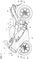
- Fig. 1 is a left side view of the straddle-type vehicle according to the present embodiment.
- an arrow FR indicates a vehicle front side
- an arrow RE indicates a vehicle rear side
- an arrow L indicates a vehicle left side
- an arrow R indicates a vehicle right side.
- a straddle-type vehicle 1 is configured by mounting various components such as an engine 16 and an electrical system on a twin spar-type vehicle body frame 10 formed by aluminum casting.
- the vehicle body frame 10 includes a pair of main frames 11 branching from a head pipe (not illustrated) to left and right and extending rearward, and a pair of down frames (not illustrated) branching from the head pipe to the left and right and extending downward.
- a rear portion of the engine 16 is supported by the pair of main frames 11, and a front portion of the engine 16 is supported by the pair of down frames.
- Front portions of the pair of main frames 11 serve as tank rails 12 located above the engine 16, and a fuel tank 17 is supported by the tank rails 12.
- Rear portions of the pair of main frames 11 serve as body frames 13 located behind the engine 16, and swing arms 18 are swingably supported in substantially intermediate positions in an upper-lower direction of the body frames 13.
- Seat rails (not illustrated) and a back stay (not illustrated) extend rearward from upper portions of the body frames 13.
- a rider seat 21 and a pillion seat 22 are supported on the seat rails behind the fuel tank 17.
- a pair of front forks 23 are supported on the head pipe via a steering shaft (not illustrated) so as to be steered.
- a front wheel 25 is rotatably supported by lower portions of the front forks 23, and an upper portion of the front wheel 25 is covered with a front fender 26.
- the swing arms 18 extend rearward from the body frames 13.
- a rear wheel 28 is rotatably supported at rear ends of the swing arms 18, and an upper side of the rear wheel 28 is covered with a rear fender 29.
- the engine 16 is coupled to the rear wheel 28 via a chain drive-type transmission mechanism, and power from the engine 16 is transmitted to the rear wheel 28 via the transmission mechanism.
- Some covers are attached to the vehicle body frame 10 of the straddle-type vehicle 1 as a vehicle body exterior.
- a front surface side of the vehicle front portion is covered with a front cowl 31, and side surface sides of the vehicle front portion are covered with a pair of side cowls 32.
- a screen 33 is provided on an upper portion of the front cowl 31, and a headlamp 34 and a pair of turn signal lamps 35 are exposed from a front surface of the front cowl 31.
- the front cowl 31, the screen 33, the headlamp 34, the pair of turn signal lamps 35, and the pair of side cowls 32 form a streamlined shape that reduces air resistance received from traveling wind.
- the screen 33 When the screen 33 is damaged, it is necessary to remove the screen 33 from the front cowl 31 and replace the screen 33 with a new screen 33. It is desirable to reduce the number of fixing members such as screws in order to facilitate replacement of the screen 33, but if the number of fixing members is too small, rigidity of the screen 33 is reduced and the screen 33 is likely to vibrate. Therefore, in the present embodiment, the screen 33 is sandwiched between the front cowl 31 and the meter panel 47 (see Fig. 4 ). The sandwiching of the screen 33 and the fixing using the fixing members are combined to secure the rigidity of the screen 33 while minimizing the number of fixing members.
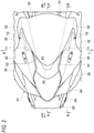
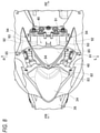
- Fig. 2 is a top view of a vehicle front portion according to the present embodiment.
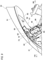
- Fig. 3 is a side view of the vehicle front portion according to the present embodiment.
- Fig. 4 is a cross-sectional view taken along a line A-A of Fig. 2 .
- Fig. 5 is a top view in which a front side cowl is removed from Fig. 2 .
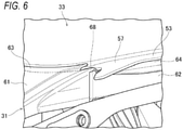
- Fig. 6 is a perspective view of a periphery of a hook according to the present embodiment.
- Fig. 7 is a top view in which a front center cowl is removed from Fig. 5 .
- Fig. 8 is a top view in which the screen is removed from Fig. 7 .
- Fig. 9 is a cross-sectional view taken along a line B-B of Fig. 2 . In Fig. 8 , for convenience of explanation, a meter and the like are omitted.
- the windbreak screen 33 is provided on an upper portion of the front cowl 31, and the pair of side cowls 32 are provided on a left edge and a right edge of the front cowl 31.
- the front cowl 31 is formed so as to cover a base end side of the screen 33 and a periphery of the central headlamp 34.
- the turn signal lamps 35 are provided between the front cowl 31 and the pair of side cowls 32.
- a streamlined shape is formed which draws a curve of an upward gradient from a front end of the headlamp 34 toward a rear end of the screen 33 and which draws a curve that widens a vehicle width from the front end of the headlamp 34 toward rear ends of the side cowls 32.
- the front cowl 31 is formed by a plurality of cowl members.
- the front surface of the front cowl 31 is formed by a front center cowl 41 that covers a front side of the screen 33, a pair of front side cowls 42 that cover both left and right sides of the screen 33, and a front under cowl 43 that covers a lower side of the headlamp 34.
- a lower surface of the front cowl 31 is formed by a part of the front under cowl 43 and a front bottom cowl (not shown) that covers the lower side of the headlamp 34.
- the screen 33 is pressed from a front side by the front center cowl 41 and the front side cowls 42.
- the meter panel 47 on which various meters 45 are installed is provided behind the front cowl 31.
- the meter panel 47 is formed by a front meter panel 48 that covers the meters 45 from a front side and a rear meter panel 49 that covers the meters 45 from a rear side.
- the screen 33 is supported from a back side by the front meter panel 48.
- the screen 33 is installed between the front cowl 31 and the meter panel 47, and a fixing structure of the screen 33 is formed by utilizing the sandwiching of the screen 33 by the front cowl 31 and the meter panel 47.
- the screen 33 includes a dome-shaped front surface portion 51 and a pair of side surface portions 52 connected to a rear side of the front surface portion 51. A tip end of each side surface portion 52 extends obliquely forward from the rear side of the front surface portion 51.
- An attachment piece 53 is formed along front edges of the front surface portion 51 and the side surface portions 52.
- the attachment piece 53 is one step lower than the front surface portion 51 and the side surface portions 52, a front surface of the attachment piece 53 is recessed more than those of the front surface portion 51 and the side surface portions 52, and a back surface of the attachment piece 53 protrudes more than those of the front surface portion 51 and the side surface portions 52. Therefore, a step 54 is formed at a boundary between the attachment piece 53 and the front surface portion 51 as well as the side surface portions 52.
- the step 54 of the screen 33 abuts against outer edges of the front center cowl 41 and the pair of front side cowls 42 (see Fig. 2 ), and the screen 33 is positioned with respect to the front center cowl 41 and the pair of front side cowls 42.
- a positioning protrusion 55 for positioning the screen 33 on the front meter panel 48 is formed at a front end of the attachment piece 53, and a pair of first fixing holes 56 for fixing the screen 33 to the front side cowls 42 are formed in both ends of the attachment piece 53.
- a pair of hooks 57 for hooking the screen 33 to the front center cowl 41 are formed at an intermediate position of the attachment piece 53.
- the front center cowl 41 includes an outer cowl 61 exposed between the pair of front side cowls 42 (see Fig. 2 ), and a pair of inner cowls 62 that enter back sides of the front side cowls 42 from both left and right sides of the outer cowl 61.
- the outer cowl 61 covers a front side of the attachment piece 53, and each inner cowl 62 enters a back side of the attachment piece 53.
- a peripheral edge of the outer cowl 61 on the front side of the attachment piece 53 serves as a pressing portion 63 that presses the attachment piece 53 from a front side
- a peripheral edge of each inner cowl 62 on the back side of the attachment piece 53 serves as a support portion 64 (a second support portion) that supports the attachment piece 53 from a back side.
- each inner cowl 62 a vicinity of the hook 57 of the attachment piece 53 is bent so as to be one step lower toward a front side of the vehicle, and a second fixing hole 65 for fixing the front side cowl 42 to the front center cowl 41 is formed in an upright surface of the bent portion.
- a rear end of each inner cowl 62 stands upright between the front surface portion 51 and the side surface portion 52 of the screen 33, and a third fixing hole 66 for fixing the front side cowl 42 to the front center cowl 41 is formed in the upright surface.
- a fourth fixing hole 67 for fixing the rear meter panel 49 (see Fig. 8 ) to the front center cowl 41 (the inner cowl 62) is formed in the vicinity of the third fixing hole 66 of each inner cowl 62.
- the pressing portion 63 of the outer cowl 61 is on the front side of the attachment piece 53 of the screen 33, and the attachment piece 53 is pressed from the front side by the pressing portion 63.
- the support portion 64 of the inner cowl 62 is on the back side of the attachment piece 53 of the screen 33, and the attachment piece 53 is supported from the back side by the support portion 64.
- a boundary portion between the pressing portion 63 and the support portion 64 is one step lower than the pressing portion 63 and one step higher than the support portion 64, and a hook portion 68 on which the hook 57 of the attachment piece 53 is hooked is formed at the boundary portion. Since the hooks 57 are hooked to hook portions 68, the screen 33 can be easily attached to the front cowl 31.
- the front side cowls 42 cover the front side of the attachment piece 53 supported by the inner cowls 62.
- a peripheral edge of each front side cowl 42 on the front side of the attachment piece 53 serves as a pressing portion 71 that presses the attachment piece 53 from a front side.
- a fifth fixing hole 72 for fixing the front side cowl 42 to the screen 33 is formed on a rear end side of each front side cowl 42.
- a pair of fifth fixing holes 72 of the front side cowls 42 are formed at positions corresponding to the pair of first fixing holes 56 (see Fig. 5 ) of the attachment piece 53, and the screen 33 is screwed to the front side cowls 42 at two left and right portions where the fixing holes 72 and 56 overlap each other.
- Fig. 5 the pair of fifth fixing holes 72 of the front side cowls 42
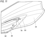
- a hook 79 that protrudes in the vicinity of the pressing portion 71 (see Fig. 2 ) is formed on the back side of each front side cowl 42.
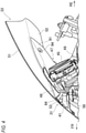
- the hook 79 is formed to be able to be hooked from a rear side, and when the attachment piece 53 of the screen 33 enters the hook 79, the screen 33 is firmly held by the front side cowl 42. Further, the hook 79 also functions as a rib that increases rigidity of the front side cowl 42. Since rigidity of the pressing portion 71 of the front side cowl 42 is increased by the hook 79, the attachment piece 53 is firmly held.
- the front meter panel 48 includes a front panel main body 81 that covers a front side of the meters 45 (see Fig. 4 ), and a support portion 82 (a first support portion) that bulges from a front surface of the front panel main body 81 and supports the attachment piece 53 from a back side.
- the support portion 82 is formed in a U shape in a top view, and faces the pressing portion 63 of the front center cowl 41 (see Fig. 5 ).
- a front surface of the support portion 82 is slightly recessed along an outer shape of the attachment piece 53, and a positioning recess 83 is formed by the recess of the support portion 82.
- the screen 33 is positioned with respect to the front meter panel 48 by the positioning protrusion 55 of the attachment piece 53 entering the positioning recess 83 of the support portion 82.
- a shallow groove 84 long in a left-right direction is formed in a front surface of the positioning recess 83, and a protrusion 58 (see Fig. 4 ) long in the left-right direction is formed on a back surface of the positioning protrusion 55 of the attachment piece 53.
- the shallow groove 84 of the positioning recess 83 and the protrusion 58 of the positioning protrusion 55 overlap each other. Therefore, it is recognized whether the positioning protrusion 55 has completely entered the positioning recess 83 according to a response when the protrusion 58 is fitted into the shallow groove 84.
- a pair of sixth fixing holes 85 for fixing the front side cowls 42 to the front meter panel 48 are formed in a pair of brackets at a rear end of the front panel main body 81.
- a fixing portion 73 extends from a back surface of the front side cowl 42 toward the inner cowl 62 of the front center cowl 41.
- a seventh fixing hole 74 for fixing the front side cowl 42 to the inner cowl 62 and the front meter panel 48 is formed in the fixing portion 73.
- the seventh fixing hole 74 of the front side cowl 42 is formed at a position corresponding to the second fixing hole 65 of the inner cowl 62 and the sixth fixing hole 85 of the front meter panel 48.
- the front side cowl 42 is screwed to the inner cowl 62 and the front meter panel 48 from an inner side of the vehicle at a portion where the fixing holes 74, 65, and 85 overlap each other.
- the rear meter panel 49 includes a rear panel main body 91 that covers a rear side of the meters 45 (see Fig. 4 ), and a pair of guide panels 92 located on an outer side of the rear panel main body 91 in a vehicle width direction.
- the pair of guide panels 92 are formed in a triangular shape in a top view, and face the front side cowls 42 (see Fig. 2 ).
- a peripheral edge of each guide panel 92 on the back side of the attachment piece 53 serves as a guide portion 93 when the screen 33 is assembled.
- An eighth fixing hole 94 for fixing the inner cowl 62 (see Fig. 5 ) of the front center cowl 41 to the rear meter panel 49 is formed on a rear end side of each guide panel 92.
- the eighth fixing hole 94 of each guide panel 92 is formed at a position corresponding to the fourth fixing hole 67 (see Fig. 5 ) of the inner cowl 62, and the inner cowl 62 (the front center cowl 41) is clipped to the rear meter panel 49 at a portion where the fixing holes 94 and 67 overlap each other.
- any fixing method of screwing, hooking, and clipping may be used for fixing exterior members such as various cowls and panels to each other.
- a front half portion of the attachment piece 53 is sandwiched between the pressing portion 63 (see Fig. 2 ) of the front center cowl 41 (the outer cowl 61) and the support portion 82 of the front meter panel 48.
- a rear half portion of the attachment piece 53 is sandwiched between the pair of pressing portions 71 of the front side cowl 42 and the pair of support portions 64 (see Fig. 5 ) of the front center cowl 41 (the inner cowls 62).
- a sandwiching structure of the attachment piece 53 is adopted, so that rigidity of the screen 33 is sufficiently secured even when there are two fixing portions of the screen 33 using a fixing member (a screw, a clip, or the like).
- tip end sides of the pair of side surface portions 52 (see Fig. 2 ) of the screen 33 are fixed to the pair of front side cowls 42.
- the tip ends of the pair of side surface portions 52 are fixed, so that rigidity of the pair of side surface portions 52 that extend outward in the vehicle width direction from the front surface portion 51 of the screen 33 is increased.
- the front half portion of the attachment piece 53 is pressed from a front side by the outer cowl 61 of the front center cowl 41, and the rear half portion of the attachment piece 53 is supported from a back side by the inner cowls 62 of the front center cowl 41. Since the sandwiching structure of the screen 33 is formed on a single member referred to as the front center cowl 41, rattling of the screen 33 is effectively prevented.
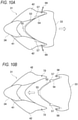
- FIGs. 10 are illustrative diagrams of the replacement work of the screen according to the present embodiment.
- Fig. 10A shows removal work of the screen
- Fig. 10B shows attachment work of the screen.
- the attachment piece 53 of the screen 33 is sandwiched between the front cowl 31 and the meter panel 47 (see Fig. 3 ).
- a pair of fixing members 99 are removed from the pair of front side cowls 42, a fixed state of the front side cowls 42 and the screen 33 is released, and the screen 33 is pulled out from between the front cowl 31 and the meter panel 47. Since the number of the fixing members 99 is minimized, a work load required for removing the fixing members 99 is reduced, and workability of the removal work of the screen 33 is improved.
- the attachment piece 53 of the screen 33 is inserted between the front cowl 31 and the meter panel 47 (see Fig. 3 ).
- a deviation of the screen 33 is adjusted by hooking the pair of hooks 57 of the attachment piece 53 on the hook portions 68 (see Fig. 6 ) of the front cowl 31 (the front center cowl 41). If there is a response when the protrusion 58 (see Fig. 4 ) of the attachment piece 53 is fitted into the shallow groove 84 (see Fig. 4 ) of the meter panel 47 (the front meter panel 48), the positioning protrusion 55 of the attachment piece 53 completely enters the positioning recess 83 (see Fig. 7 ) of the meter panel 47. Further, the step 54 on the front surface of the attachment piece 53 abuts against a peripheral edge of the front cowl 31.
- the pair of fifth fixing holes 72 of the pair of front side cowls 42 are aligned with the pair of first fixing holes 56 of the attachment piece 53 by positioning the screen 33. Then, the fixing members 99 are inserted into the fixing holes 72 and 56 from front sides of the front side cowls 42, and the front side cowls 42 and the attachment piece 53 are fixed by the fixing members 99, so that the screen 33 is attached between the front cowl 31 and the meter panel 47. Since the number of the fixing members 99 is minimized, a work load required for fixing the fixing members 99 is reduced, and workability of the attachment work of the screen 33 is improved.
- the attachment piece 53 of the screen 33 is sandwiched between the support portion 82 of the meter panel 47 and the pressing portions 63 and 71 of the front cowl 31.
- a combination of sandwiching the attachment piece 53 of the screen 33 and the fixing using the fixing members 99 can minimize the number of fixing members 99, and improve the workability of the replacement work of the screen 33 while securing the rigidity of the screen 33. Further, exposure of the fixing members 99 is reduced and appearance is also improved.
- the front cowl is divided into three parts by the front center cowl and the pair of front side cowls, but a front cowl integrally formed by welding a plurality of members or the like may be used.
- the attachment piece of the screen is pressed from the front side by the front center cowl and the pair of front side cowls, but the attachment piece of the screen may be pressed by one of the front center cowl and the pair of front side cowls.
- the front center cowl includes the outer cowl and the inner cowls, but the front center cowl may include at least the outer cowl.
- the attachment piece of the screen is supported from the back side by the front meter panel and the rear meter panel, but the attachment piece of the screen may be supported by one of the front meter panel and the rear meter panel.
- the rear meter panel is provided with the pair of guide panels, but the front meter panel may be provided with the pair of guide panels.
- an entire region of the attachment piece of the screen is sandwiched between the front cowl and the meter panel, but a part of the attachment piece of the screen may be sandwiched between the front cowl and the meter panel.
- the positioning protrusion is formed on the attachment piece of the screen and the positioning recess is formed in the meter panel, but the positioning recess may be formed in the attachment piece of the screen and the positioning protrusion may be formed on the meter panel.
- the positioning portion may be formed on one of the attachment piece of the screen and the meter panel, the positioned portion may be formed on the other of the attachment piece of the screen and the meter panel, and shapes of the positioning portion and the positioned portion are not particularly limited.
- the positioning portion and the positioned portion are formed on the attachment piece of the screen and the meter panel, but the positioning portion may be formed on one of the attachment piece of the screen and the front cowl, and the positioned portion may be formed on the other of the attachment piece of the screen and the front cowl.
- the positioning protrusion may be formed on the attachment piece of the screen, and the positioning recess may be formed in the back surface of the front cowl.
- the protrusion is formed on the back surface of the attachment piece of the screen, and the shallow groove is formed in a front surface of the meter panel, but the shallow groove may be formed in the back surface of the attachment piece of the screen, and the protrusion may be formed on the front surface of the meter panel. Further, the protrusion may be formed on one of the front surface of the attachment piece of the screen and the back surface of the front cowl, and the shallow groove may be formed in the other of the front surface of the attachment piece of the screen and the back surface of the front cowl. Shapes of the protrusion and the shallow groove are not particularly limited as long as the protrusion and the shallow groove have a shape that makes insertion of the screen feel responsive.
- the screen is screwed to the front cowl, but the method of fixing the screen and the front cowl is not particularly limited.
- the screen may be fixed to the front cowl by clipping.
- the fixing structure of the screen of the saddle-ridden vehicle of the present embodiment is not limited to a motorcycle of a tourer type, and may be adopted for motorcycles of other types. Further, the saddle-ridden vehicle is not limited to all vehicles in which a rider rides in a posture of straddling a seat, but also includes a vehicle of a scooter type in which the rider rides without straddling a seat.
- the fixing structure of the screen (33) of the present embodiment is a fixing structure of a screen, including the front cowl (31) that covers the vehicle front portion, the meter panel (47) disposed at a rear side of the front cowl, and a screen (33) installed between the front cowl (31) and the meter panel (47), in which the attachment piece (53) is formed along the front edge of the screen, the first support portion (82) that supports the attachment piece from the back side is formed on the meter panel, and the pressing portion (63, 71) that presses the attachment piece from the front side is formed on the front cowl.
- the attachment piece of the screen is sandwiched between the support portion of the meter panel and the pressing portion of the front cowl.
- the combination of sandwiching the attachment piece of the screen and the fixing using the fixing members can minimize the number of fixing members, and improve the workability of the replacement work of the screen while securing the rigidity of the screen.
- the second support portion (64) that supports the attachment piece from the back side is formed on the front cowl, the pressing portion presses the front half portion of the attachment piece from the front side, the second support portion supports the rear half portion of the attachment piece from the back side, and the pressing portion and the second support portion are formed as a single member.
- the front half portion of the attachment piece of the screen is pressed from the front side by the single member, and the rear half portion of the attachment piece of the screen is supported from the back side by the single member, so that the rattling of the screen is effectively prevented.
- the hook portion (68) disposed at the boundary portion between the pressing portion and the other support portion is formed on the front cowl, and the hook (57) to be hooked on the hook portion is formed on the attachment piece. According to this configuration, since the hook is hooked on the hook portion of the front cowl, the screen can be easily attached to the front cowl.
- the positioning portion (the positioning recess 83) is formed on one of the attachment piece and the first support portion, and the positioned portion (the positioning protrusion 55) to be positioned on the positioning portion is formed on the other of the attachment piece and the first support portion. According to this configuration, the screen is easily positioned with respect to the meter panel.
- the dome-shaped front surface portion (51) and the pair of side surface portions (52) connected to the rear side of the front surface portion are formed on the screen, and the screen is fixed to the front cowl on the tip end sides of the pair of side surface portions. According to this configuration, rigidity of the pair of side surface portions that extend outward in the vehicle width direction from the front surface portion of the screen is increased.
Landscapes
- Engineering & Computer Science (AREA)
- Mechanical Engineering (AREA)
- Body Structure For Vehicles (AREA)
Abstract
Description
- The present invention relates to a fixing structure of a screen.
- In a saddle-ridden vehicle such as a motorcycle, a screen is provided on an upper portion of a front cowl in order to protect an occupant from traveling wind (for example, see Patent Literature 1). In a fixing structure of a screen described in Patent Literature 1, a front edge of the screen enters a back side of a front cowl, and the front edge of the screen is fixed by a fixing member such as a screw from a front side of the front cowl. In this type of fixing structure of the screen, rigidity of the screen is increased by, for example, increasing thickness of the screen or the number of fixed portions of the screen so that the screen does not vibrate due to the traveling wind.
- Patent Literature 1:
JP-A-H10-273082 - It is important that the fixing structure of the screen makes it easy to replace the screen, but if the number of fixing members is reduced, rigidity of the screen is reduced. On the other hand, if the number of fixing members is increased in consideration of the rigidity of the screen, replacement work of the screen becomes complicated. As described above, there is a trade-off relationship between workability of the replacement work of the screen and the rigidity of the screen.
- The present invention has been made in view of the above circumstances, and an object thereof is to provide a fixing structure of a screen that can easily replace the screen while securing rigidity of the screen.
- According to one advantageous aspect of the preset invention, there is provided a fixing structure of a screen, including
- a front cowl configured to cover a vehicle front portion;
- a meter panel disposed at a rear side of the front cowl; and
- a screen installed between the front cowl and the meter panel, wherein
- an attachment piece is formed along a front edge of the screen,
- a first support portion configured to support the attachment piece from a back side is formed on the meter panel, and
- a pressing portion configured to press the attachment piece from a front side is formed on the front cowl.
- According to a fixing structure of a screen of one aspect of the present invention, an attachment piece of the screen is sandwiched between a support portion of a meter panel and a pressing portion of a front cowl. A combination of sandwiching the attachment piece of the screen and fixing using fixing members can minimize the number of fixing members, and improve workability of replacement work of the screen while securing rigidity of the screen.
-
-
Fig. 1 is a left side view of a saddle-ridden vehicle according to the present embodiment. -
Fig. 2 is a top view of a vehicle front portion according to the present embodiment. -
Fig. 3 is a side view of the vehicle front portion according to the present embodiment. -
Fig. 4 is a cross-sectional view taken along a line A-A ofFig. 2 . -
Fig. 5 is a top view in which a front side cowl is removed fromFig. 2 . -
Fig. 6 is a perspective view of a periphery of a hook according to the present embodiment. -
Fig. 7 is a top view in which a front center cowl is removed fromFig. 5 . -
Fig. 8 is a top view in which a screen is removed fromFig. 7 . -
Fig. 9 is a cross-sectional view taken along a line B-B ofFig. 2 . -
Figs. 10A and 10B are illustrative diagrams of replacement work of the screen according to the present embodiment. -
Fig. 11 is a perspective view of a part of the screen of the present embodiment when viewed from a back surface side. - In a fixing structure of a screen according to one aspect of the present invention, a screen is installed between a front cowl that covers a vehicle front portion and a meter panel behind the front cowl. An attachment piece is formed along a front edge of the screen. The attachment piece is supported from a back side by a support portion of the meter panel, and the attachment piece is pressed from a front side by a pressing portion of the front cowl, so that the attachment piece of the screen is sandwiched between the meter panel and the front cowl. A combination of the sandwiching of the attachment piece of the screen and fixing using fixing members minimizes the number of the fixing members, secures rigidity of the screen, and improves workability of replacement work of the screen.
- Hereinafter, the present embodiment will be described in detail with reference to the accompanying drawings.
Fig. 1 is a left side view of the straddle-type vehicle according to the present embodiment. In the following drawings, an arrow FR indicates a vehicle front side, an arrow RE indicates a vehicle rear side, an arrow L indicates a vehicle left side, and an arrow R indicates a vehicle right side. - As illustrated in
Fig. 1 , a straddle-type vehicle 1 is configured by mounting various components such as anengine 16 and an electrical system on a twin spar-typevehicle body frame 10 formed by aluminum casting. Thevehicle body frame 10 includes a pair ofmain frames 11 branching from a head pipe (not illustrated) to left and right and extending rearward, and a pair of down frames (not illustrated) branching from the head pipe to the left and right and extending downward. A rear portion of theengine 16 is supported by the pair ofmain frames 11, and a front portion of theengine 16 is supported by the pair of down frames. By supporting theengine 16 with thevehicle body frame 10, the rigidity of the entire vehicle is ensured. - Front portions of the pair of
main frames 11 serve astank rails 12 located above theengine 16, and afuel tank 17 is supported by thetank rails 12. Rear portions of the pair ofmain frames 11 serve asbody frames 13 located behind theengine 16, andswing arms 18 are swingably supported in substantially intermediate positions in an upper-lower direction of thebody frames 13. Seat rails (not illustrated) and a back stay (not illustrated) extend rearward from upper portions of thebody frames 13. Arider seat 21 and apillion seat 22 are supported on the seat rails behind thefuel tank 17. - A pair of
front forks 23 are supported on the head pipe via a steering shaft (not illustrated) so as to be steered. Afront wheel 25 is rotatably supported by lower portions of thefront forks 23, and an upper portion of thefront wheel 25 is covered with afront fender 26. Theswing arms 18 extend rearward from thebody frames 13. Arear wheel 28 is rotatably supported at rear ends of theswing arms 18, and an upper side of therear wheel 28 is covered with arear fender 29. Theengine 16 is coupled to therear wheel 28 via a chain drive-type transmission mechanism, and power from theengine 16 is transmitted to therear wheel 28 via the transmission mechanism. - Some covers are attached to the
vehicle body frame 10 of the straddle-type vehicle 1 as a vehicle body exterior. For example, a front surface side of the vehicle front portion is covered with afront cowl 31, and side surface sides of the vehicle front portion are covered with a pair ofside cowls 32. Ascreen 33 is provided on an upper portion of thefront cowl 31, and aheadlamp 34 and a pair ofturn signal lamps 35 are exposed from a front surface of thefront cowl 31. Thefront cowl 31, thescreen 33, theheadlamp 34, the pair ofturn signal lamps 35, and the pair ofside cowls 32 form a streamlined shape that reduces air resistance received from traveling wind. - When the
screen 33 is damaged, it is necessary to remove thescreen 33 from thefront cowl 31 and replace thescreen 33 with anew screen 33. It is desirable to reduce the number of fixing members such as screws in order to facilitate replacement of thescreen 33, but if the number of fixing members is too small, rigidity of thescreen 33 is reduced and thescreen 33 is likely to vibrate. Therefore, in the present embodiment, thescreen 33 is sandwiched between thefront cowl 31 and the meter panel 47 (seeFig. 4 ). The sandwiching of thescreen 33 and the fixing using the fixing members are combined to secure the rigidity of thescreen 33 while minimizing the number of fixing members. - Hereinafter, the fixing structure of the screen will be described with reference to
Figs. 2 to 9 .Fig. 2 is a top view of a vehicle front portion according to the present embodiment.Fig. 3 is a side view of the vehicle front portion according to the present embodiment.Fig. 4 is a cross-sectional view taken along a line A-A ofFig. 2 .Fig. 5 is a top view in which a front side cowl is removed fromFig. 2 .Fig. 6 is a perspective view of a periphery of a hook according to the present embodiment.Fig. 7 is a top view in which a front center cowl is removed fromFig. 5 .Fig. 8 is a top view in which the screen is removed fromFig. 7 .Fig. 9 is a cross-sectional view taken along a line B-B ofFig. 2 . InFig. 8 , for convenience of explanation, a meter and the like are omitted. - As shown in
Figs. 2 and3 , thewindbreak screen 33 is provided on an upper portion of thefront cowl 31, and the pair ofside cowls 32 are provided on a left edge and a right edge of thefront cowl 31. Thefront cowl 31 is formed so as to cover a base end side of thescreen 33 and a periphery of thecentral headlamp 34. Theturn signal lamps 35 are provided between thefront cowl 31 and the pair of side cowls 32. A streamlined shape is formed which draws a curve of an upward gradient from a front end of theheadlamp 34 toward a rear end of thescreen 33 and which draws a curve that widens a vehicle width from the front end of theheadlamp 34 toward rear ends of the side cowls 32. - The
front cowl 31 is formed by a plurality of cowl members. The front surface of thefront cowl 31 is formed by afront center cowl 41 that covers a front side of thescreen 33, a pair offront side cowls 42 that cover both left and right sides of thescreen 33, and a front undercowl 43 that covers a lower side of theheadlamp 34. A lower surface of thefront cowl 31 is formed by a part of the front undercowl 43 and a front bottom cowl (not shown) that covers the lower side of theheadlamp 34. Thescreen 33 is pressed from a front side by thefront center cowl 41 and the front side cowls 42. - As shown in
Fig. 4 , themeter panel 47 on whichvarious meters 45 are installed is provided behind thefront cowl 31. Themeter panel 47 is formed by afront meter panel 48 that covers themeters 45 from a front side and arear meter panel 49 that covers themeters 45 from a rear side. Thescreen 33 is supported from a back side by thefront meter panel 48. Thescreen 33 is installed between thefront cowl 31 and themeter panel 47, and a fixing structure of thescreen 33 is formed by utilizing the sandwiching of thescreen 33 by thefront cowl 31 and themeter panel 47. - As shown in
Fig. 5 , thescreen 33 includes a dome-shapedfront surface portion 51 and a pair ofside surface portions 52 connected to a rear side of thefront surface portion 51. A tip end of eachside surface portion 52 extends obliquely forward from the rear side of thefront surface portion 51. Anattachment piece 53 is formed along front edges of thefront surface portion 51 and theside surface portions 52. Theattachment piece 53 is one step lower than thefront surface portion 51 and theside surface portions 52, a front surface of theattachment piece 53 is recessed more than those of thefront surface portion 51 and theside surface portions 52, and a back surface of theattachment piece 53 protrudes more than those of thefront surface portion 51 and theside surface portions 52. Therefore, astep 54 is formed at a boundary between theattachment piece 53 and thefront surface portion 51 as well as theside surface portions 52. - The
step 54 of thescreen 33 abuts against outer edges of thefront center cowl 41 and the pair of front side cowls 42 (seeFig. 2 ), and thescreen 33 is positioned with respect to thefront center cowl 41 and the pair of front side cowls 42. Apositioning protrusion 55 for positioning thescreen 33 on the front meter panel 48 (seeFig. 7 ) is formed at a front end of theattachment piece 53, and a pair of first fixing holes 56 for fixing thescreen 33 to thefront side cowls 42 are formed in both ends of theattachment piece 53. Further, a pair ofhooks 57 for hooking thescreen 33 to thefront center cowl 41 are formed at an intermediate position of theattachment piece 53. - The
front center cowl 41 includes anouter cowl 61 exposed between the pair of front side cowls 42 (seeFig. 2 ), and a pair ofinner cowls 62 that enter back sides of thefront side cowls 42 from both left and right sides of theouter cowl 61. Theouter cowl 61 covers a front side of theattachment piece 53, and eachinner cowl 62 enters a back side of theattachment piece 53. A peripheral edge of theouter cowl 61 on the front side of theattachment piece 53 serves as apressing portion 63 that presses theattachment piece 53 from a front side, and a peripheral edge of eachinner cowl 62 on the back side of theattachment piece 53 serves as a support portion 64 (a second support portion) that supports theattachment piece 53 from a back side. - In each
inner cowl 62, a vicinity of thehook 57 of theattachment piece 53 is bent so as to be one step lower toward a front side of the vehicle, and asecond fixing hole 65 for fixing thefront side cowl 42 to thefront center cowl 41 is formed in an upright surface of the bent portion. A rear end of eachinner cowl 62 stands upright between thefront surface portion 51 and theside surface portion 52 of thescreen 33, and athird fixing hole 66 for fixing thefront side cowl 42 to thefront center cowl 41 is formed in the upright surface. Afourth fixing hole 67 for fixing the rear meter panel 49 (seeFig. 8 ) to the front center cowl 41 (the inner cowl 62) is formed in the vicinity of thethird fixing hole 66 of eachinner cowl 62. - As shown in
Fig. 6 , thepressing portion 63 of theouter cowl 61 is on the front side of theattachment piece 53 of thescreen 33, and theattachment piece 53 is pressed from the front side by thepressing portion 63. Thesupport portion 64 of theinner cowl 62 is on the back side of theattachment piece 53 of thescreen 33, and theattachment piece 53 is supported from the back side by thesupport portion 64. A boundary portion between thepressing portion 63 and thesupport portion 64 is one step lower than thepressing portion 63 and one step higher than thesupport portion 64, and ahook portion 68 on which thehook 57 of theattachment piece 53 is hooked is formed at the boundary portion. Since thehooks 57 are hooked to hookportions 68, thescreen 33 can be easily attached to thefront cowl 31. - As shown in
Fig. 2 , thefront side cowls 42 cover the front side of theattachment piece 53 supported by theinner cowls 62. A peripheral edge of eachfront side cowl 42 on the front side of theattachment piece 53 serves as apressing portion 71 that presses theattachment piece 53 from a front side. Afifth fixing hole 72 for fixing thefront side cowl 42 to thescreen 33 is formed on a rear end side of eachfront side cowl 42. A pair of fifth fixing holes 72 of thefront side cowls 42 are formed at positions corresponding to the pair of first fixing holes 56 (seeFig. 5 ) of theattachment piece 53, and thescreen 33 is screwed to thefront side cowls 42 at two left and right portions where the fixing holes 72 and 56 overlap each other. As shown inFig. 11 , ahook 79 that protrudes in the vicinity of the pressing portion 71 (seeFig. 2 ) is formed on the back side of eachfront side cowl 42. Thehook 79 is formed to be able to be hooked from a rear side, and when theattachment piece 53 of thescreen 33 enters thehook 79, thescreen 33 is firmly held by thefront side cowl 42. Further, thehook 79 also functions as a rib that increases rigidity of thefront side cowl 42. Since rigidity of thepressing portion 71 of thefront side cowl 42 is increased by thehook 79, theattachment piece 53 is firmly held. - As shown in
Figs. 7 and8 , thefront meter panel 48 includes a front panelmain body 81 that covers a front side of the meters 45 (seeFig. 4 ), and a support portion 82 (a first support portion) that bulges from a front surface of the front panelmain body 81 and supports theattachment piece 53 from a back side. Thesupport portion 82 is formed in a U shape in a top view, and faces thepressing portion 63 of the front center cowl 41 (seeFig. 5 ). A front surface of thesupport portion 82 is slightly recessed along an outer shape of theattachment piece 53, and apositioning recess 83 is formed by the recess of thesupport portion 82. Thescreen 33 is positioned with respect to thefront meter panel 48 by thepositioning protrusion 55 of theattachment piece 53 entering thepositioning recess 83 of thesupport portion 82. - A
shallow groove 84 long in a left-right direction is formed in a front surface of thepositioning recess 83, and a protrusion 58 (seeFig. 4 ) long in the left-right direction is formed on a back surface of thepositioning protrusion 55 of theattachment piece 53. In a state where thepositioning protrusion 55 enters thepositioning recess 83, theshallow groove 84 of thepositioning recess 83 and theprotrusion 58 of thepositioning protrusion 55 overlap each other. Therefore, it is recognized whether thepositioning protrusion 55 has completely entered thepositioning recess 83 according to a response when theprotrusion 58 is fitted into theshallow groove 84. A pair of sixth fixing holes 85 for fixing the front side cowls 42 to thefront meter panel 48 are formed in a pair of brackets at a rear end of the front panelmain body 81. - As shown in
Fig. 9 , a fixingportion 73 extends from a back surface of thefront side cowl 42 toward theinner cowl 62 of thefront center cowl 41. Aseventh fixing hole 74 for fixing thefront side cowl 42 to theinner cowl 62 and thefront meter panel 48 is formed in the fixingportion 73. Theseventh fixing hole 74 of thefront side cowl 42 is formed at a position corresponding to thesecond fixing hole 65 of theinner cowl 62 and the sixth fixinghole 85 of thefront meter panel 48. Thefront side cowl 42 is screwed to theinner cowl 62 and thefront meter panel 48 from an inner side of the vehicle at a portion where the fixing holes 74, 65, and 85 overlap each other. - Returning to
Figs. 7 and8 , therear meter panel 49 includes a rear panelmain body 91 that covers a rear side of the meters 45 (seeFig. 4 ), and a pair ofguide panels 92 located on an outer side of the rear panelmain body 91 in a vehicle width direction. The pair ofguide panels 92 are formed in a triangular shape in a top view, and face the front side cowls 42 (seeFig. 2 ). A peripheral edge of eachguide panel 92 on the back side of theattachment piece 53 serves as aguide portion 93 when thescreen 33 is assembled. - An eighth fixing
hole 94 for fixing the inner cowl 62 (seeFig. 5 ) of the front center cowl 41 to therear meter panel 49 is formed on a rear end side of eachguide panel 92. Theeighth fixing hole 94 of eachguide panel 92 is formed at a position corresponding to the fourth fixing hole 67 (seeFig. 5 ) of theinner cowl 62, and the inner cowl 62 (the front center cowl 41) is clipped to therear meter panel 49 at a portion where the fixing holes 94 and 67 overlap each other. For fixing exterior members such as various cowls and panels to each other, any fixing method of screwing, hooking, and clipping may be used. - In the fixing structure of the
screen 33 configured as described above, a front half portion of theattachment piece 53 is sandwiched between the pressing portion 63 (seeFig. 2 ) of the front center cowl 41 (the outer cowl 61) and thesupport portion 82 of thefront meter panel 48. A rear half portion of theattachment piece 53 is sandwiched between the pair ofpressing portions 71 of thefront side cowl 42 and the pair of support portions 64 (seeFig. 5 ) of the front center cowl 41 (the inner cowls 62). Such a sandwiching structure of theattachment piece 53 is adopted, so that rigidity of thescreen 33 is sufficiently secured even when there are two fixing portions of thescreen 33 using a fixing member (a screw, a clip, or the like). - Particularly, tip end sides of the pair of side surface portions 52 (see
Fig. 2 ) of thescreen 33 are fixed to the pair of front side cowls 42. The tip ends of the pair ofside surface portions 52 are fixed, so that rigidity of the pair ofside surface portions 52 that extend outward in the vehicle width direction from thefront surface portion 51 of thescreen 33 is increased. Further, in the present embodiment, the front half portion of theattachment piece 53 is pressed from a front side by theouter cowl 61 of thefront center cowl 41, and the rear half portion of theattachment piece 53 is supported from a back side by theinner cowls 62 of thefront center cowl 41. Since the sandwiching structure of thescreen 33 is formed on a single member referred to as thefront center cowl 41, rattling of thescreen 33 is effectively prevented. - Replacement work of the screen will be described with reference to
Figs. 10. Figs. 10 are illustrative diagrams of the replacement work of the screen according to the present embodiment.Fig. 10A shows removal work of the screen, andFig. 10B shows attachment work of the screen. - As shown in
Fig. 10A , theattachment piece 53 of thescreen 33 is sandwiched between thefront cowl 31 and the meter panel 47 (seeFig. 3 ). In the removal work of thescreen 33, a pair of fixingmembers 99 are removed from the pair offront side cowls 42, a fixed state of thefront side cowls 42 and thescreen 33 is released, and thescreen 33 is pulled out from between thefront cowl 31 and themeter panel 47. Since the number of the fixingmembers 99 is minimized, a work load required for removing the fixingmembers 99 is reduced, and workability of the removal work of thescreen 33 is improved. - As shown in
Fig. 10B , in the attachment work of thescreen 33, theattachment piece 53 of thescreen 33 is inserted between thefront cowl 31 and the meter panel 47 (seeFig. 3 ). A deviation of thescreen 33 is adjusted by hooking the pair ofhooks 57 of theattachment piece 53 on the hook portions 68 (seeFig. 6 ) of the front cowl 31 (the front center cowl 41). If there is a response when the protrusion 58 (seeFig. 4 ) of theattachment piece 53 is fitted into the shallow groove 84 (seeFig. 4 ) of the meter panel 47 (the front meter panel 48), thepositioning protrusion 55 of theattachment piece 53 completely enters the positioning recess 83 (seeFig. 7 ) of themeter panel 47. Further, thestep 54 on the front surface of theattachment piece 53 abuts against a peripheral edge of thefront cowl 31. - The pair of fifth fixing holes 72 of the pair of
front side cowls 42 are aligned with the pair of first fixing holes 56 of theattachment piece 53 by positioning thescreen 33. Then, the fixingmembers 99 are inserted into the fixing holes 72 and 56 from front sides of thefront side cowls 42, and thefront side cowls 42 and theattachment piece 53 are fixed by the fixingmembers 99, so that thescreen 33 is attached between thefront cowl 31 and themeter panel 47. Since the number of the fixingmembers 99 is minimized, a work load required for fixing the fixingmembers 99 is reduced, and workability of the attachment work of thescreen 33 is improved. - As described above, according to the present embodiment, the
attachment piece 53 of thescreen 33 is sandwiched between thesupport portion 82 of themeter panel 47 and thepressing portions front cowl 31. A combination of sandwiching theattachment piece 53 of thescreen 33 and the fixing using the fixingmembers 99 can minimize the number of fixingmembers 99, and improve the workability of the replacement work of thescreen 33 while securing the rigidity of thescreen 33. Further, exposure of the fixingmembers 99 is reduced and appearance is also improved. - In the present embodiment, the front cowl is divided into three parts by the front center cowl and the pair of front side cowls, but a front cowl integrally formed by welding a plurality of members or the like may be used.
- In the present embodiment, the attachment piece of the screen is pressed from the front side by the front center cowl and the pair of front side cowls, but the attachment piece of the screen may be pressed by one of the front center cowl and the pair of front side cowls.
- In the present embodiment, the front center cowl includes the outer cowl and the inner cowls, but the front center cowl may include at least the outer cowl.
- In the present embodiment, the attachment piece of the screen is supported from the back side by the front meter panel and the rear meter panel, but the attachment piece of the screen may be supported by one of the front meter panel and the rear meter panel. In the present embodiment, the rear meter panel is provided with the pair of guide panels, but the front meter panel may be provided with the pair of guide panels.
- In the present embodiment, an entire region of the attachment piece of the screen is sandwiched between the front cowl and the meter panel, but a part of the attachment piece of the screen may be sandwiched between the front cowl and the meter panel.
- In the present embodiment, the positioning protrusion is formed on the attachment piece of the screen and the positioning recess is formed in the meter panel, but the positioning recess may be formed in the attachment piece of the screen and the positioning protrusion may be formed on the meter panel. Further, the positioning portion may be formed on one of the attachment piece of the screen and the meter panel, the positioned portion may be formed on the other of the attachment piece of the screen and the meter panel, and shapes of the positioning portion and the positioned portion are not particularly limited.
- In the present embodiment, the positioning portion and the positioned portion are formed on the attachment piece of the screen and the meter panel, but the positioning portion may be formed on one of the attachment piece of the screen and the front cowl, and the positioned portion may be formed on the other of the attachment piece of the screen and the front cowl. For example, the positioning protrusion may be formed on the attachment piece of the screen, and the positioning recess may be formed in the back surface of the front cowl.
- In the present embodiment, the protrusion is formed on the back surface of the attachment piece of the screen, and the shallow groove is formed in a front surface of the meter panel, but the shallow groove may be formed in the back surface of the attachment piece of the screen, and the protrusion may be formed on the front surface of the meter panel. Further, the protrusion may be formed on one of the front surface of the attachment piece of the screen and the back surface of the front cowl, and the shallow groove may be formed in the other of the front surface of the attachment piece of the screen and the back surface of the front cowl. Shapes of the protrusion and the shallow groove are not particularly limited as long as the protrusion and the shallow groove have a shape that makes insertion of the screen feel responsive.
- In the present embodiment, the screen is screwed to the front cowl, but the method of fixing the screen and the front cowl is not particularly limited. For example, the screen may be fixed to the front cowl by clipping.
- The fixing structure of the screen of the saddle-ridden vehicle of the present embodiment is not limited to a motorcycle of a tourer type, and may be adopted for motorcycles of other types. Further, the saddle-ridden vehicle is not limited to all vehicles in which a rider rides in a posture of straddling a seat, but also includes a vehicle of a scooter type in which the rider rides without straddling a seat.
- As described above, the fixing structure of the screen (33) of the present embodiment is a fixing structure of a screen, including the front cowl (31) that covers the vehicle front portion, the meter panel (47) disposed at a rear side of the front cowl, and a screen (33) installed between the front cowl (31) and the meter panel (47), in which the attachment piece (53) is formed along the front edge of the screen, the first support portion (82) that supports the attachment piece from the back side is formed on the meter panel, and the pressing portion (63, 71) that presses the attachment piece from the front side is formed on the front cowl. According to this configuration, the attachment piece of the screen is sandwiched between the support portion of the meter panel and the pressing portion of the front cowl. The combination of sandwiching the attachment piece of the screen and the fixing using the fixing members can minimize the number of fixing members, and improve the workability of the replacement work of the screen while securing the rigidity of the screen.
- In the fixing structure of the screen of the present embodiment, the second support portion (64) that supports the attachment piece from the back side is formed on the front cowl, the pressing portion presses the front half portion of the attachment piece from the front side, the second support portion supports the rear half portion of the attachment piece from the back side, and the pressing portion and the second support portion are formed as a single member. According to this configuration, the front half portion of the attachment piece of the screen is pressed from the front side by the single member, and the rear half portion of the attachment piece of the screen is supported from the back side by the single member, so that the rattling of the screen is effectively prevented.
- In the fixing structure of the screen of the present embodiment, the hook portion (68) disposed at the boundary portion between the pressing portion and the other support portion is formed on the front cowl, and the hook (57) to be hooked on the hook portion is formed on the attachment piece. According to this configuration, since the hook is hooked on the hook portion of the front cowl, the screen can be easily attached to the front cowl.
- In the fixing structure of the screen of the present embodiment, the positioning portion (the positioning recess 83) is formed on one of the attachment piece and the first support portion, and the positioned portion (the positioning protrusion 55) to be positioned on the positioning portion is formed on the other of the attachment piece and the first support portion. According to this configuration, the screen is easily positioned with respect to the meter panel.
- In the fixing structure of the screen of the present embodiment, the dome-shaped front surface portion (51) and the pair of side surface portions (52) connected to the rear side of the front surface portion are formed on the screen, and the screen is fixed to the front cowl on the tip end sides of the pair of side surface portions. According to this configuration, rigidity of the pair of side surface portions that extend outward in the vehicle width direction from the front surface portion of the screen is increased.
- Although the present embodiment has been described, the above-described embodiment and modifications may be combined entirely or partially as another embodiment.
- The technique of the present invention is not limited to the above-described embodiment, and various changes, substitutions, and modifications may be made without departing from the spirit of the technical concept of the present invention. Further, the present invention may be implemented using other methods as long as the technical concept can be implemented by the methods through advance of the technology or other derivative technology. Therefore, the claims cover all embodiments that may be included within the scope of the technical concept.
Claims (5)
- A fixing structure of a screen (33), characterized by comprisinga front cowl (31) configured to cover a vehicle front portion;a meter panel (47) disposed at a rear side of the front cowl (31); anda screen (33) installed between the front cowl (31) and the meter panel (47), whereinan attachment piece (53) is formed along a front edge of the screen (33),a first support portion (82) configured to support the attachment piece (53) from a back side is formed on the meter panel (47), anda pressing portion (63, 71) configured to press the attachment piece (53) from a front side is formed on the front cowl (31).
- The fixing structure of the screen (33) according to claim 1, whereina second support portion (64) configured to support the attachment piece (53) from a back side is formed on the front cowl (31), andthe pressing portion (63) presses a front half portion of the attachment piece (53) from a front side,the second support portion (64) supports a rear half portion of the attachment piece (53) from a back side, andthe pressing portion (71) and the second support portion (64) are formed as a single member.
- The fixing structure of the screen (33) according to claim 2, whereina hook portion (68) disposed at a boundary portion between the pressing portion (71) and the second support portion (64) is formed on the front cowl (31), anda hook (57) to be hooked on the hook portion (68) is formed on the attachment piece (53).
- The fixing structure of the screen (33) according to any one of claims 1 to 3, whereina positioning portion (83) is formed on one of the attachment piece (53) and the first support portion (82), anda positioned portion (55) to be positioned on the positioning portion (83) is formed on the other of the attachment piece (53) and the first support portion (82).
- The fixing structure of the screen (33) according to any one of claims 1 to 4, whereina dome-shaped front surface portion (51) and a pair of side surface portions (52) connected to a rear side of the front surface portion (51) are formed on the screen (33), andthe screen (33) is fixed to the front cowl (31) on tip end sides of the pair of side surface portions (52).
Applications Claiming Priority (1)
| Application Number | Priority Date | Filing Date | Title |
|---|---|---|---|
| JP2020149717A JP7552165B2 (en) | 2020-09-07 | 2020-09-07 | Screen fixing structure |
Publications (2)
| Publication Number | Publication Date |
|---|---|
| EP3964433A1 true EP3964433A1 (en) | 2022-03-09 |
| EP3964433B1 EP3964433B1 (en) | 2025-12-17 |
Family
ID=77564016
Family Applications (1)
| Application Number | Title | Priority Date | Filing Date |
|---|---|---|---|
| EP21194055.6A Active EP3964433B1 (en) | 2020-09-07 | 2021-08-31 | Fixing structure of a windbreak screen of a saddle-ridden vehicle |
Country Status (3)
| Country | Link |
|---|---|
| US (1) | US11964724B2 (en) |
| EP (1) | EP3964433B1 (en) |
| JP (1) | JP7552165B2 (en) |
Citations (5)
| Publication number | Priority date | Publication date | Assignee | Title |
|---|---|---|---|---|
| JPS6332980U (en) * | 1986-08-20 | 1988-03-03 | ||
| JPS6422592U (en) * | 1987-07-31 | 1989-02-06 | ||
| JPH10273082A (en) | 1997-03-31 | 1998-10-13 | Suzuki Motor Corp | Motorcycle cowling brace |
| JP2004168306A (en) * | 2004-02-05 | 2004-06-17 | Suzuki Motor Corp | Motorcycle front cowling |
| JP2009107570A (en) * | 2007-10-31 | 2009-05-21 | Yamaha Motor Co Ltd | Saddle riding vehicle |
Family Cites Families (4)
| Publication number | Priority date | Publication date | Assignee | Title |
|---|---|---|---|---|
| US3819226A (en) * | 1972-10-10 | 1974-06-25 | Coleman Co | Attachment assembly for snowmobile windshield |
| JP2008195241A (en) * | 2007-02-13 | 2008-08-28 | Yamaha Motor Co Ltd | Vehicle with cowling |
| EP2917094B1 (en) * | 2012-11-12 | 2020-09-30 | Indian Motorcycle International, LLC | Two-wheeled vehicle |
| US20190061858A1 (en) * | 2017-08-24 | 2019-02-28 | Geoffrey Bruce Goodrick | Windshield arrangement |
-
2020
- 2020-09-07 JP JP2020149717A patent/JP7552165B2/en active Active
-
2021
- 2021-08-31 US US17/462,321 patent/US11964724B2/en active Active
- 2021-08-31 EP EP21194055.6A patent/EP3964433B1/en active Active
Patent Citations (5)
| Publication number | Priority date | Publication date | Assignee | Title |
|---|---|---|---|---|
| JPS6332980U (en) * | 1986-08-20 | 1988-03-03 | ||
| JPS6422592U (en) * | 1987-07-31 | 1989-02-06 | ||
| JPH10273082A (en) | 1997-03-31 | 1998-10-13 | Suzuki Motor Corp | Motorcycle cowling brace |
| JP2004168306A (en) * | 2004-02-05 | 2004-06-17 | Suzuki Motor Corp | Motorcycle front cowling |
| JP2009107570A (en) * | 2007-10-31 | 2009-05-21 | Yamaha Motor Co Ltd | Saddle riding vehicle |
Also Published As
| Publication number | Publication date |
|---|---|
| JP7552165B2 (en) | 2024-09-18 |
| US11964724B2 (en) | 2024-04-23 |
| JP2022044200A (en) | 2022-03-17 |
| EP3964433B1 (en) | 2025-12-17 |
| US20220073164A1 (en) | 2022-03-10 |
Similar Documents
| Publication | Publication Date | Title |
|---|---|---|
| WO2011111651A1 (en) | Two-wheeled motor vehicle | |
| JP5205168B2 (en) | Body front support structure | |
| MX2007011569A (en) | Meter support structure for saddle riding type vehicle . | |
| EP3378751B1 (en) | Rear fender supporting structure of saddle-type vehicle | |
| JP2012136137A (en) | Vehicle handlebar support structure | |
| EP2128007A1 (en) | Motorcycle | |
| JP3842966B2 (en) | Speedometer mounting structure for motorcycles | |
| JP5460526B2 (en) | Front structure of motorcycle | |
| EP3964435B1 (en) | Louver member | |
| EP3964433B1 (en) | Fixing structure of a windbreak screen of a saddle-ridden vehicle | |
| JP3584720B2 (en) | Motorcycle | |
| EP4488153A1 (en) | Vehicle front structure | |
| JP7177800B2 (en) | Step mounting structure | |
| EP1642811B1 (en) | Windscreen mounting structure in light vehicles | |
| JP2009090883A (en) | Saddle riding vehicle | |
| JP2014108748A (en) | Motorcycle | |
| JP7225632B2 (en) | Straddle-type vehicle front structure | |
| JP5539121B2 (en) | Motorcycle | |
| JP5271234B2 (en) | Saddle riding vehicle | |
| JP7597841B2 (en) | Saddle-type vehicle | |
| JP3426853B2 (en) | Front fender structure of motorcycle | |
| JP5145141B2 (en) | Motorcycle cowling equipment | |
| JP2015143088A (en) | Saddle-riding type vehicle including rear grip | |
| WO2018047127A1 (en) | Support structure for rear panel of step-through scooter type motorcycle | |
| US20230202604A1 (en) | Saddled vehicle |
Legal Events
| Date | Code | Title | Description |
|---|---|---|---|
| PUAI | Public reference made under article 153(3) epc to a published international application that has entered the european phase |
Free format text: ORIGINAL CODE: 0009012 |
|
| STAA | Information on the status of an ep patent application or granted ep patent |
Free format text: STATUS: REQUEST FOR EXAMINATION WAS MADE |
|
| 17P | Request for examination filed |
Effective date: 20210831 |
|
| AK | Designated contracting states |
Kind code of ref document: A1 Designated state(s): AL AT BE BG CH CY CZ DE DK EE ES FI FR GB GR HR HU IE IS IT LI LT LU LV MC MK MT NL NO PL PT RO RS SE SI SK SM TR |
|
| STAA | Information on the status of an ep patent application or granted ep patent |
Free format text: STATUS: EXAMINATION IS IN PROGRESS |
|
| 17Q | First examination report despatched |
Effective date: 20230317 |
|
| GRAP | Despatch of communication of intention to grant a patent |
Free format text: ORIGINAL CODE: EPIDOSNIGR1 |
|
| STAA | Information on the status of an ep patent application or granted ep patent |
Free format text: STATUS: GRANT OF PATENT IS INTENDED |
|
| INTG | Intention to grant announced |
Effective date: 20250729 |
|
| GRAS | Grant fee paid |
Free format text: ORIGINAL CODE: EPIDOSNIGR3 |
|
| GRAA | (expected) grant |
Free format text: ORIGINAL CODE: 0009210 |
|
| STAA | Information on the status of an ep patent application or granted ep patent |
Free format text: STATUS: THE PATENT HAS BEEN GRANTED |
|
| AK | Designated contracting states |
Kind code of ref document: B1 Designated state(s): AL AT BE BG CH CY CZ DE DK EE ES FI FR GB GR HR HU IE IS IT LI LT LU LV MC MK MT NL NO PL PT RO RS SE SI SK SM TR |
|
| REG | Reference to a national code |
Ref country code: CH Ref legal event code: F10 Free format text: ST27 STATUS EVENT CODE: U-0-0-F10-F00 (AS PROVIDED BY THE NATIONAL OFFICE) Effective date: 20251217 Ref country code: GB Ref legal event code: FG4D |
|
| REG | Reference to a national code |
Ref country code: DE Ref legal event code: R096 Ref document number: 602021044461 Country of ref document: DE |
|
| REG | Reference to a national code |
Ref country code: LT Ref legal event code: MG9D |
|
| PG25 | Lapsed in a contracting state [announced via postgrant information from national office to epo] |
Ref country code: NO Free format text: LAPSE BECAUSE OF FAILURE TO SUBMIT A TRANSLATION OF THE DESCRIPTION OR TO PAY THE FEE WITHIN THE PRESCRIBED TIME-LIMIT Effective date: 20260317 |
|
| PG25 | Lapsed in a contracting state [announced via postgrant information from national office to epo] |
Ref country code: FI Free format text: LAPSE BECAUSE OF FAILURE TO SUBMIT A TRANSLATION OF THE DESCRIPTION OR TO PAY THE FEE WITHIN THE PRESCRIBED TIME-LIMIT Effective date: 20251217 Ref country code: HR Free format text: LAPSE BECAUSE OF FAILURE TO SUBMIT A TRANSLATION OF THE DESCRIPTION OR TO PAY THE FEE WITHIN THE PRESCRIBED TIME-LIMIT Effective date: 20251217 |
|
| PG25 | Lapsed in a contracting state [announced via postgrant information from national office to epo] |
Ref country code: RS Free format text: LAPSE BECAUSE OF FAILURE TO SUBMIT A TRANSLATION OF THE DESCRIPTION OR TO PAY THE FEE WITHIN THE PRESCRIBED TIME-LIMIT Effective date: 20260317 |
|
| REG | Reference to a national code |
Ref country code: NL Ref legal event code: MP Effective date: 20251217 |
|
| PG25 | Lapsed in a contracting state [announced via postgrant information from national office to epo] |
Ref country code: LV Free format text: LAPSE BECAUSE OF FAILURE TO SUBMIT A TRANSLATION OF THE DESCRIPTION OR TO PAY THE FEE WITHIN THE PRESCRIBED TIME-LIMIT Effective date: 20251217 |
|
| PG25 | Lapsed in a contracting state [announced via postgrant information from national office to epo] |
Ref country code: BG Free format text: LAPSE BECAUSE OF FAILURE TO SUBMIT A TRANSLATION OF THE DESCRIPTION OR TO PAY THE FEE WITHIN THE PRESCRIBED TIME-LIMIT Effective date: 20251217 |