EP3964420A1 - Control system and method for monitoring the integrity of the rails of a railway track - Google Patents

Control system and method for monitoring the integrity of the rails of a railway track Download PDF

Info

Publication number
EP3964420A1
EP3964420A1 EP20305986.0A EP20305986A EP3964420A1 EP 3964420 A1 EP3964420 A1 EP 3964420A1 EP 20305986 A EP20305986 A EP 20305986A EP 3964420 A1 EP3964420 A1 EP 3964420A1
Authority
EP
European Patent Office
Prior art keywords
rail
sensor
control
det
sensors
Prior art date
Legal status (The legal status is an assumption and is not a legal conclusion. Google has not performed a legal analysis and makes no representation as to the accuracy of the status listed.)
Pending
Application number
EP20305986.0A
Other languages
German (de)
French (fr)
Inventor
Francesco Campedelli
Current Assignee (The listed assignees may be inaccurate. Google has not performed a legal analysis and makes no representation or warranty as to the accuracy of the list.)
Alstom Holdings SA
Original Assignee
Alstom Transport Technologies SAS
Priority date (The priority date is an assumption and is not a legal conclusion. Google has not performed a legal analysis and makes no representation as to the accuracy of the date listed.)
Filing date
Publication date
Application filed by Alstom Transport Technologies SAS filed Critical Alstom Transport Technologies SAS
Priority to EP20305986.0A priority Critical patent/EP3964420A1/en
Publication of EP3964420A1 publication Critical patent/EP3964420A1/en
Pending legal-status Critical Current

Links

Images

Classifications

    • BPERFORMING OPERATIONS; TRANSPORTING
    • B61RAILWAYS
    • B61LGUIDING RAILWAY TRAFFIC; ENSURING THE SAFETY OF RAILWAY TRAFFIC
    • B61L23/00Control, warning or like safety means along the route or between vehicles or trains
    • B61L23/04Control, warning or like safety means along the route or between vehicles or trains for monitoring the mechanical state of the route
    • B61L23/042Track changes detection
    • B61L23/044Broken rails
    • BPERFORMING OPERATIONS; TRANSPORTING
    • B61RAILWAYS
    • B61LGUIDING RAILWAY TRAFFIC; ENSURING THE SAFETY OF RAILWAY TRAFFIC
    • B61L1/00Devices along the route controlled by interaction with the vehicle or train
    • B61L1/18Railway track circuits
    • B61L1/181Details
    • B61L1/186Use of rectified alternating current
    • BPERFORMING OPERATIONS; TRANSPORTING
    • B61RAILWAYS
    • B61LGUIDING RAILWAY TRAFFIC; ENSURING THE SAFETY OF RAILWAY TRAFFIC
    • B61L1/00Devices along the route controlled by interaction with the vehicle or train
    • B61L1/18Railway track circuits
    • B61L1/181Details
    • B61L1/188Use of coded current
    • BPERFORMING OPERATIONS; TRANSPORTING
    • B61RAILWAYS
    • B61LGUIDING RAILWAY TRAFFIC; ENSURING THE SAFETY OF RAILWAY TRAFFIC
    • B61L27/00Central railway traffic control systems; Trackside control; Communication systems specially adapted therefor
    • B61L27/50Trackside diagnosis or maintenance, e.g. software upgrades
    • B61L27/53Trackside diagnosis or maintenance, e.g. software upgrades for trackside elements or systems, e.g. trackside supervision of trackside control system conditions
    • BPERFORMING OPERATIONS; TRANSPORTING
    • B61RAILWAYS
    • B61LGUIDING RAILWAY TRAFFIC; ENSURING THE SAFETY OF RAILWAY TRAFFIC
    • B61L1/00Devices along the route controlled by interaction with the vehicle or train
    • B61L1/02Electric devices associated with track, e.g. rail contacts
    • B61L1/025Electric devices associated with track, e.g. rail contacts actuated by variation of resistance or by piezoelectricity

Definitions

  • the present invention relates to a control system and a method for monitoring the integrity of the rails of a railway track.
  • the rails play a fundamental role and for them the risk of having defective parts is intrinsic and substantially unavoidable, for instance due to the working conditions under which they are used, e.g. climatic conditions which are usually variable and in some cases might be very harsh, or due to mechanical stresses, for example due to the friction and weight exerted by the travelling vehicles, or just due to the usual aging and mechanical wearing occurring during lifetime service, et cetera.
  • a rail may incur in different types of defects, such as superficial defects, hot spots, cracks, breakages, et cetera.
  • some vehicles are provided with on board cameras that capture images of the lines, which images are later on examined to identify possible defects; clearly, this solution can identify only superficial defects and is highly influenced by the visibility conditions.
  • the distance between the two points may influence the results; further, the testing operations should be carried out when there are not vehicles travelling along the railway line under inspection or nearby, otherwise the results can be negatively influenced by their disturbances; for example, even the inspection vehicle carrying out a test may introduce undesired vibrations in the rail under testing.
  • an object of the present invention is to provide a solution capable of properly monitoring the integrity of the rails of a railway track with a reliability substantially improved over known solutions.
  • Another object of the present invention is to provide a solution capable of properly monitoring the integrity of the rails of a railway track while meeting at the same time the highest level of safety integrity level ("SIL"), such as for example the requirements of a SIL4 system.
  • SIL safety integrity level
  • Yet a further object of the present invention is to realize a solution capable of properly monitoring the integrity of the rails of a railway track which is relatively easy to be realized at a competitive costs, and which can be applied without any modification or at most with simple modifications to railway lines of different types, be them non-electrified lines, AC or DC electrified lines, railway lines with a high or a low- traffic density.
  • a control system for monitoring the integrity of the rails of a railway track characterized in that it comprises:
  • control system according to the present invention may comprise one or more of the following features, which may be combined in any technical feasible combination:
  • each of the above listed terms means and encompasses electronic circuits or parts thereof, as well as stored, embedded or running software codes and/or routines, algorithms, or complete programs, suitably designed for achieving the technical result and/or the functional performances for which such means are devised.
  • transversal or transversally When the terms transversal or transversally are hereby used, they have to be understood as encompassing a direction non-parallel to the part(s) they refer to, and perpendicularity has to be considered a specific case of transverse direction.
  • FIG 1 schematically illustrates a possible embodiment of a control system according to the invention, indicated therein by the overall reference number 100, which is suitable to monitor the integrity of the two rails A and B of a railway track, indicated in figure 1 by the reference number 1.
  • the control system 100 comprises at least:
  • the at least one control and processing unit 30 is configured to calculate:
  • the at least one control and processing unit 30 is further configured to calculate the difference between the first and second values calculated and to generate a control signal S c indicative of a defective part along one of the first and second rails A, B if the difference calculated exceeds a predetermined threshold.
  • the control signal S c can be sent for example, via transmissions cables 35, or via a wireless device, such as the exemplary one illustrated in figure 1 by the reference number 36, towards a remote control center overseeing an entire railway line to which the monitored railway track 1 belongs to.
  • each of the first, second, third and fourth sensors 10, 11, 20 and 21 can provide the respective signals to the at least one control and processing unit 30, via a cabled connections 15 or in a wireless manner.
  • the first and second sensors 10 and 11 are magnetic field sensors configured to sense values indicative of an actual magnetic field generated around the first rail A by a current I A flowing along the first rail A itself.
  • the third and fourth sensors 20 and 21 are magnetic field sensors configured to sense values indicative of an actual magnetic field generated around the second rail B by a current I B flowing along the second rail B itself.
  • the magnetic field lines around the rails A or B are schematically represented in figure 2 by the arrows 5.
  • the first sensor 10 operatively associated to the first rail A and the third sensor 20 operatively associated to the second rail B are substantially equal to each other; in turn, the second sensor 11 operatively associated to the first rail A and the fourth sensor 21 operatively associated to the second rail B are substantially equal to each other and of a type different from the first and third sensors 10 and 20.
  • a first couple is based on a first type of physical properties or detecting technology in order to detect a parameter indicative of the actual current flowing in the rails A and B
  • a second couple is based on a second type of physical properties or detecting technology in order to detect a parameter indicative of the actual current flowing in the rails A and B.
  • the first and second parameters detected are the same, i.e. the intensity of the magnetic fields generated around the first rail A and correspondingly around the second rail B by the current I A flowing along the first rail A and respectively the current I B flowing along the second rail B.
  • the first sensor 10 and the third sensor 20 are Hall-effect sensors.
  • the second sensor 11 and the fourth sensor 21 are magneto-resistive sensors.
  • each of the first, second, third and fourth sensors 10, 11, 20 and 21, can be positioned inside a respective casing, illustrated schematically in figure 1 by the reference number 25; for instance, each casing 25 can be conveniently dust and water proof and, depending on the applications, it can be also realized with a material suitable to shield external disturbing magnetic fields if needed.
  • one or more of, preferably all the first, second third and fourth magnetic field sensors 10, 11, 20 and 21 are positioned each inside a respective magnetic flux concentrator, schematically indicated in figure 1 by the reference number 26.
  • control system 100 comprises a control station 50 housing inside the at least one control and processing unit 30.
  • control station 50 is positioned along the railway track 1, for example substantially at the same position where the first, second, third and fourth sensors 10, 11, 20 and 21 are positioned.
  • the at least one control and processing unit 30 and the associated first, second, third and fourth sensors 10, 11, 20 and 21 can be supplied via power derived from the catenary line 51 itself; the same applies if the railway track 1 is powered by an AC source.
  • the control station 50 comprises a power harvesting system 52, comprising for example one or more solar panels and related electronics, which is configured to harvest power, e.g. for powering the at least one processing unit 30 and also the associated first, second, third and fourth sensors 10, 11, 20 and 21.
  • a power harvesting system 52 comprising for example one or more solar panels and related electronics, which is configured to harvest power, e.g. for powering the at least one processing unit 30 and also the associated first, second, third and fourth sensors 10, 11, 20 and 21.
  • the first, second, third and fourth sensors 10, 11, 20 and 21 may comprise or be coupled with dedicated power harvesting devices configured to harvest power and supply each one or more of such sensors.
  • control system 100 further comprises at least one test device 40 which is positioned along the railway track 1 and is configured to generate a test current to be injected inside the first and second rails A, B of the railway track 1 in order to monitor their integrity.
  • test device 40 can be housed also inside the control station 50.
  • the currents injected in the rails A and B by the test device 40 are those generating the magnetic fields detected by the first, second, third and fourth sensors indicated by the reference numbers 80, 81, 90 and 91 whose signals are then received by the at least control and processing unit 30 and properly processed, as previously described, in order to verify any defective part present along the first rail A or the second rail B.
  • Each sensor 80, 81, 90 and 91 can be a single sensor of the same kind as 10, 11, 20 or 21 if redundancy is not required; otherwise for each of sensor 80, 81, 90 and 91 for example a couple of a Hall effect sensor and a magnetoresistive sensor can be used, since it is not known "a priori" in which direction relative to power stations 101 the test current will flow; hence, in this last case a total of eight sensors will be used.
  • test device 40 can be realized according to various possible circuital schemes, per se known or readily available to those skilled in the art, and thus not described herein in further details, according to two main reference schemes different from each other based on the fact whether the test device 40 is used in a railway track which is already electrified and therefore a voltage source is available or not, in which case the test device 40 comprises also an own power generator.
  • test device can be realized as a variant of a buck or buck-boost high frequency switching power converter, configured to output a current, as for example illustrated in figure 4 , where there is depicted a circuital exemplary embodiment for such test device 40.
  • the upper switch 41 is PWM-modulated via a pulse generator or PWM modulator 42 so that the average current injected in the rails A and B is maintained at a certain level.
  • the current comes from a remote traction power station through the catenary line 51, and returns to it through the rails A and B, in particular one half for each rail.
  • the duty cycle of the switch 41 is kept very low to keep conduction losses at a minimum, and to use a high frequency current transformer 43 which is connected in series with an inductor 44 to sense the current and use the relative signal S F as feedback for the pulse generator or PWM modulator 42.
  • the switch 41 can be realized with an appropriate cascade connection of high voltage, low power SiC IGBT or Mosfet, of any suitable type currently available on the market, connected in series to the current transformer 43 and the inductor 44, in order to realize the switch 41.
  • diodes 45 are connected in parallel to the assembly formed by the serial connection of the inductor 44 and the transformer 43.
  • Diodes 45 are an appropriate cascade connection of high voltage SiC diodes of any suitable type currently available on the market.
  • the reference signal for the PWM modulator 42 can be a fixed one, or - better - a low frequency coded one, so that the injected current can vary between two or more levels, following a predefined pattern or a pattern generated by the electronics of the associated detection system.
  • test current generated in this way is equivalent to the current drawn by the train; the currents in the rails will be measured by the two pair of sensors and their differential evaluated to asses if the rails are in good conditions or not.
  • the power needed to generate the currents to be injected into the rails A and B can be provided for example by one traction power station 101 used for powering the track 1 itself; in such cases, the test device 40 can be placed along the railway track 1 in the centre of the electric "line" between two traction power stations 101, as illustrated in figure 3 .
  • test device 40 can comprise an own power harvesting unit, indicated schematically in figure 3 by the dotted box 48, which is configured to harvest and store power to be used for self-powering, or it can be powered by the power harvesting system 52 of the control station 50.
  • an own power harvesting unit indicated schematically in figure 3 by the dotted box 48, which is configured to harvest and store power to be used for self-powering, or it can be powered by the power harvesting system 52 of the control station 50.
  • the test device 40 can be conveniently used to monitor the integrity of the rails A and B of a railway track 1, either when the railway track 1 is part of a non-electrified line, and/or where the majority of trains travelling along the track 1 are not electric ones, and/or there are long intervals of time without passages of trains.
  • test device 40 allows performing monitoring of the rails with any sufficient frequency of monitoring tests necessary for example to meet SIL4-type requirements.
  • the at least one control and processing unit 30 comprises a first control and processing unit 31 and a second control and processing unit 32, schematically represented in figure 1 by the reference numbers 31 and 32, respectively.
  • the first control and processing unit 31 is arranged to be operatively connected to and receive the signals indicative of the corresponding magnetic field detected from one of the first and second sensors 10 and 11, and from one of the third and fourth sensors 20, 21 of different type
  • the second control and processing unit 32 is arranged to be operatively connected to and receive signals indicative of the corresponding magnetic field detected from the other one of the first and second sensors 10, 11 and from the other one of the third and fourth sensors 20 and 21 having a different type.
  • the first control and processing unit 31 can receive the signals S1 det and S4de, from the Hall-effect sensor 10 and the magneto-resistive sensor 21, while the second control and processing unit 31 can receive the signals S2 det and S3 det from the magneto-resistive sensor 11 and the Hall-effect sensor 20.
  • one of the first and second control and processing units 31 and 32 can receive the signals provided by the Hall-effect sensors, and the other one can receive only the signals from the magneto-resistive sensors.
  • the presence of the two control and processing units 31 and 32 improves redundancy, reliability and robustness of the control system 100.
  • the other ones e.g. the magneto-resistive sensors will continue to detect the magnetic fields correctly, and at least one of the control and processing units 31 and 32, exchanging data between them, would be able to detect anyhow the presence of a defective part on a rail A or B, and generate a corresponding control signal S C .
  • the two control and processing units 31 and 32 can be mutually coordinated to follow an appropriate and coordinated decisional process in order to solve any conflicting computation between them and properly discriminate among inconsistent detections, due for example to an actual external perturbation versus an actual malfunctioning of any sensor; for example, references values for the currents I A and I B can be prerecorded and taken as reference, for example on the basis of a nominal behavior for the railway track 1, or based on precalibration/autocalibration tests, or on periodic calibration tests executed injecting known currents, e.g. via the test device 40.
  • FIG 5 there is schematically illustrated a method 200 for monitoring the integrity of the rails A, B of a railway track 1, which can be implemented for example by a control system as previously described.
  • the method 200 comprises at least the following steps:
  • detecting 210 and 220 can be executed in parallel to each other or in whatever suitable sequence.
  • the method 200 can implement all steps and sub-steps corresponding to the execution of the various functionalities and performances described above for the control system 100, which are not hereby replicated for the sake of conciseness.
  • control system 100 and method 200 according to the present invention achieve the intended aim and objects, since they allow detecting, timely and precisely, the presence of a potentially defective part of any part of a rail, according to a solution having an increased reliability and which improves therefore the overall safety of railway operations along the railway track 1 thus monitored.
  • control system 100 may comprise a plurality of control stations 50 distributed at a certain distance from each other along a railway line and each of the control station can be associated with two couples of sensors of different type as previously described;
  • control and processing unit 30, or each of the two control and processing units 31 and 32 can be constituted by, or comprise, any suitable processor-based device, e.g. a processor of a type commercially available, suitably programmed and provided to the extent necessary with circuitry, in order to perform the innovative functionalities devised for the control system 100 according to the present invention.

Landscapes

  • Engineering & Computer Science (AREA)
  • Mechanical Engineering (AREA)
  • Automation & Control Theory (AREA)
  • Health & Medical Sciences (AREA)
  • Biomedical Technology (AREA)
  • General Health & Medical Sciences (AREA)
  • Train Traffic Observation, Control, And Security (AREA)

Abstract

A control system (100) and a method (200) for monitoring the integrity of the rails (A, B) of a railway track (1), wherein a first sensor (10) and a second sensor (11) are positioned close to each other in proximity of a first rail (A) of the railway track (1) and are configured to detect, independently from each other, a first parameter indicative of the intensity of a current (I<sub>A</sub>) flowing along the first rail (A) and to provide to at least one control and processing unit (30) first signals (S1<sub>det</sub>) and respective second signals (S2<sub>det</sub>) indicative of the actual value respectively detected for the first parameter; a third sensor (20) and a fourth sensor (21) are positioned close to each other in proximity of a second rail (B) of the railway track (1) and are configured to detect, independently from each other, a second parameter indicative of the intensity of a current (I<sub>B</sub>) flowing along the second rail (B) and to provide to the at least one control and processing unit (30) third signals (S3<sub>det</sub>) and respective fourth signals (S4<sub>det</sub>) indicative of the actual value respectively detected for the second parameter. The at least one control and processing unit (30) is configured to calculate a first value indicative of the intensity (I<sub>A</sub>) of the current flowing along the first rail (A) based on at least one of the first and second signals (S1<sub>det</sub>, S2<sub>det</sub>) received from the first and second sensors (10, 11), and a second value indicative of the intensity (I<sub>B</sub>) of the current flowing along the second rail (B) based on at least one of the third and fourth signals (S3<sub>det</sub>, S4<sub>det</sub>) received from the third and fourth sensors (20, 21). The at least one control and processing unit (30) is further configured to calculate the difference between the first and second values calculated and to generate a control signal (S<sub>c</sub>) indicative of a defective part of one of the first and second rails (A, B) if the difference calculated exceeds a predetermined threshold.

Description

  • The present invention relates to a control system and a method for monitoring the integrity of the rails of a railway track.
  • As known, in the field of railways transportation, the requirement of safety is of outmost importance and it is therefore mandatory that the various parts involved in the operations are installed and maintained at the adequate standard of efficiency.
  • To this end, the rails play a fundamental role and for them the risk of having defective parts is intrinsic and substantially unavoidable, for instance due to the working conditions under which they are used, e.g. climatic conditions which are usually variable and in some cases might be very harsh, or due to mechanical stresses, for example due to the friction and weight exerted by the travelling vehicles, or just due to the usual aging and mechanical wearing occurring during lifetime service, et cetera.
  • As a consequence, a rail may incur in different types of defects, such as superficial defects, hot spots, cracks, breakages, et cetera.
  • The occurrence of such defective conditions is usually not instantaneous and in any case it is important that the onset of any defective part or condition is detected as timely and as precisely as possible in order to introduce corrective actions and prevent malfunctioning or failures that could result in long and unacceptable perturbations, or even disruptions, of the railway traffic.
  • Some solutions currently used for monitoring the integrity of a rail foresee the use of vehicles provided with specific equipment mounted on board in order to carry out the inspection.
  • For example, some vehicles are provided with on board cameras that capture images of the lines, which images are later on examined to identify possible defects; clearly, this solution can identify only superficial defects and is highly influenced by the visibility conditions.
  • In order to detect possible defective parts inside the structure of a rail, some other solutions carry out for example vibration tests.
  • In particular, these solutions imply the use of devices that are brought into direct contact with a point of a rail where ultrasonic sound waves are injected into the rail; then, the response of the structure, in terms of vibrations, is sensed at a second point of the rail and thereafter analysed.
  • In such solutions, the distance between the two points may influence the results; further, the testing operations should be carried out when there are not vehicles travelling along the railway line under inspection or nearby, otherwise the results can be negatively influenced by their disturbances; for example, even the inspection vehicle carrying out a test may introduce undesired vibrations in the rail under testing.
  • Yet other solutions foresee the use of track circuits or other suitable dedicated sensors that are positioned along the railway tracks and are meant to provide monitoring signals indicative of the actual condition of the monitored rails.
  • Although such solutions allow monitoring somehow the integrity of the rails, they can suffer reliability problems, due for example to the influence of environmental conditions, negatively affecting the detecting capabilities and accuracy of the sensors used, thus impacting the level of safety of the railway operations or causing inappropriate alarms.
  • Hence, it is a main aim of the present invention to provide a solution able to mitigate at least partially at least some of the above mentioned drawbacks.
  • Within this aim, an object of the present invention is to provide a solution capable of properly monitoring the integrity of the rails of a railway track with a reliability substantially improved over known solutions.
  • Another object of the present invention is to provide a solution capable of properly monitoring the integrity of the rails of a railway track while meeting at the same time the highest level of safety integrity level ("SIL"), such as for example the requirements of a SIL4 system.
  • Yet a further object of the present invention is to realize a solution capable of properly monitoring the integrity of the rails of a railway track which is relatively easy to be realized at a competitive costs, and which can be applied without any modification or at most with simple modifications to railway lines of different types, be them non-electrified lines, AC or DC electrified lines, railway lines with a high or a low- traffic density.
  • The above mentioned aim and objects, as well as any other which may become apparent hereinafter, are achieved by a control system for monitoring the integrity of the rails of a railway track, characterized in that it comprises:
    • at least one control and processing unit;
    • a first sensor and a second sensor which are positioned close to each other in proximity of a first rail of the railway track, said first and second sensors being configured to detect, independently from each other, a first parameter indicative of the intensity of a current flowing along said first rail and to provide to the at least one control and processing unit first signals and respective second signals indicative of the actual value respectively detected for said first parameter;
    • a third sensor and a fourth sensor which are positioned close to each other in proximity of a second rail of the railway track, said third and fourth sensors being configured to detect, independently from each other, a second parameter indicative of the intensity of a current flowing along the second rail and to provide to the at least one control and processing unit third signals and respective fourth signals indicative of the actual value respectively detected for said second parameter;
    and wherein the at least one control and processing unit is configured to calculate a first value indicative of the intensity of said current flowing along the first rail based on at least one of the first and second signals received from the first and second sensors, and a second value indicative of the intensity of said current flowing along the second rail based on at least one of the third and fourth signals received from the third and fourth sensors, and wherein the at least one control and processing unit is further configured to calculate the difference between the first and second values calculated and to generate a control signal indicative of a defective part of one of the first and second rails if the difference calculated exceeds a predetermined threshold.
  • According to some embodiments, the control system according to the present invention may comprise one or more of the following features, which may be combined in any technical feasible combination:
    • the first and second sensors are magnetic field sensors configured to sense values indicative of an actual magnetic field generated around the first rail by said current flowing along said first rail, and said third and fourth sensors are magnetic field sensors configured to sense values indicative of an actual magnetic field generated around the second rail by said current flowing along said second rail;
    • the first sensor and the third sensor are substantially equal to each other and said second sensor and said fourth sensor are substantially equal to each other and of a type different from said first and third sensors;
    • the first sensor and the third sensor are Hall-effect sensors;
    • the second sensor and the fourth sensor are magneto-resistive sensors;
    • one or more of the first, second third and fourth magnetic field sensors are positioned each inside a respective magnetic flux concentrator;
    • the control system further comprises at least one test device which is positioned along the railway track and is configured to generate a test current to be injected inside said first and second rails of the railway track;
    • the at least one test device comprises a power harvesting unit for self-powering the at least one test device;
    • the at least one control and processing unit is housed inside a control station which is positioned along the railway track and comprises a power harvesting unit for powering at least said one control and processing unit;
    • the at least one control and processing unit comprises a first control and processing unit and a second control and processing unit, wherein the first control and processing unit is arranged to be connected to and receive signals from one of the first and second sensors and one of the third and fourth sensors, and the second control and processing unit is arranged to be connected to and receive signals from the other one of the first and second sensors and the other one of the third and fourth sensors.
  • The above mentioned aim and objects, as well as any other which may become apparent hereinafter, are achieved by a method for monitoring the integrity of the rails of a railway track, characterized in that it comprises at least the following steps:
    • (a): detecting, by means of a first sensor and of a second sensor which are positioned close to each other in proximity of a first rail of the railway track, independently from each other, a first parameter indicative of the intensity of a current flowing along said first rail and providing to at least one control and processing unit first signals and respective second signals indicative of the actual value respectively detected for said first parameter;
    • (b): detecting, by means of a third sensor and of a fourth sensor which are positioned close to each other in proximity of a second rail of the railway track, independently from each other, a second parameter indicative of the intensity of a current flowing along said second rail of the railway track and providing to said at least one control and processing unit third signals and respective fourth signals indicative of the actual value respectively detected for said second parameter; and, by means of said at least one control and processing unit:
    • (c): calculating, a first value indicative of the intensity of said current flowing along the first rail based on at least one of the first and second signals received from the first and second sensor, and a second value indicative of the intensity of said current flowing along the second rail based on at least one of the third and fourth signals received from the third and fourth sensor;
    • (d): calculating, the difference between the calculated first and second values;
    • (e): generating a control signal indicative of a defective part of one of the first and second rails if the calculated difference exceeds a predetermined threshold.
  • Further characteristics and advantages will become apparent from the description of some preferred but not exclusive exemplary embodiments of a system and a method according to the invention, illustrated only by way of non-limitative examples with the accompanying drawings, wherein:
    • Figure 1 is a view schematically illustrating an example of a control system according to the invention applied to the rails of a railway track;
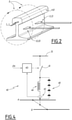
    • Figure 2 schematically shows a couple of sensors of the control system of figure 1 positioned along a rail of a railway track;
    • Figure 3 is a schematic circuital representation of a possible embodiment of a control system according to the present invention comprising a test device;
    • Figure 4 schematically shows a circuital exemplary embodiment of a test device usable in the control system according to the invention;
    • Figure 5 is a flow chart illustrating a method for monitoring the integrity of the rails of a railway track according to the invention.
  • It should be noted that in order to clearly and concisely describe the present disclosure, the drawings may not necessarily be to scale and certain features of the disclosure may be shown in somewhat schematic form.
  • Further, when the term "adapted" or "arranged" or "configured" or "shaped", is used herein while referring to any component as a whole, or to any part of a component, or to a combination of components, it has to be understood that it means and encompasses correspondingly either the structure, and/or configuration and/or form and/or positioning.
  • In particular, for electronic and/or software means, each of the above listed terms means and encompasses electronic circuits or parts thereof, as well as stored, embedded or running software codes and/or routines, algorithms, or complete programs, suitably designed for achieving the technical result and/or the functional performances for which such means are devised.
  • When the terms transversal or transversally are hereby used, they have to be understood as encompassing a direction non-parallel to the part(s) they refer to, and perpendicularity has to be considered a specific case of transverse direction.
  • In addition, when the terms substantial or substantially are used with reference to moving parts, e.g. two parts moving substantially solidly to each other, it has to be understood that they move together apart from unavoidable mechanical inertia, while when referring to relative positioning, e.g. one part substantially parallel to another part, it has to be understood as encompassing a tolerance of plus or minus 5°.
  • Finally, in the following description and claims, the numeral cardinals first, second, third et cetera..., will be used only for the sake of clarity of description and in no way they should be understood as limiting for whatsoever reason. In particular, the indication of a component referred to for instance as the "third..." does not imply necessarily the presence or strict need of the preceding "first" or "second" ones, unless such presence is clearly evident for the correct functioning of the subject embodiment(s), nor that the order should be the one described in the illustrated exemplary embodiment(s); further, when using the terms first, second, et cetera, while referring for example to a first parameter and to a second parameter, such distinction is used primarily for clarity purposes and the two parameters may be the same or different, depending on and as it can be inferred from the context they are used.
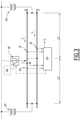
  • Figure 1 schematically illustrates a possible embodiment of a control system according to the invention, indicated therein by the overall reference number 100, which is suitable to monitor the integrity of the two rails A and B of a railway track, indicated in figure 1 by the reference number 1.
  • The control system 100 comprises at least:
    • at least one control and processing unit, schematically indicated in figure 1 by the reference number 30;
    • a first sensor 10 which is positioned in proximity of a first rail A of the railway track 1, i.e. at a certain distance from the surface of the first rail A, as for example illustrated in figure 2. In particular the first sensor 10 is configured to detect, preferably in a contactless manner, a first parameter indicative of the intensity of a current IA flowing along the first rail A and to provide to the at least one control and processing unit 30, first signals S1det indicative of the actual value detected by itself for the first parameter;
    • a second sensor 11 which is positioned in proximity of the first rail A and close to the first sensor 10, likewise at a certain distance from the surface of the first rail A, as for example illustrated in figure 2. The second sensor 11 is configured to detect, independently from the first sensor 10, preferably in a contactless manner with respect to the first rail ail A, the same first parameter indicative of the intensity of said current IA flowing along the first rail A and to provide to the at least one control and processing unit 30 respective second signals S2det indicative of the actual value detected by itself for the first parameter;
    • a third sensor 20 which is positioned in proximity of a second rail B of the railway track 1, i.e. at a certain distance from the surface of the second rail B, in a manner similar for example to that of the first sensor 10 relative to the first rail A. The third sensor 20 is configured to detect, preferably in a contactless manner, a second parameter indicative of the intensity of a current IB flowing along the second rail B and to provide to the at least one control and processing unit 30, third signals (S3det) indicative of the actual value detected by itself for the second parameter; and
    • a fourth sensor 21 which is positioned in proximity of the second rail B close to the third sensor 20, e.g. at a certain distance from the surface of the second rail B, for example with respect to the third sensor 20 and the second rail B, similarly to the positioning of the second sensor 11 relative to the first sensor 10 and to the first rail A illustrated in figure 2. The fourth sensor 21 is configured to detect, independently from the third sensor 20, preferably in a contactless manner with respect to the second rail B, the same second parameter indicative of the intensity of said current IB flowing along the second rail B, and to provide to the at least one control and processing unit 30 fourth signals S4det indicative of the actual value detected by itself for the second parameter.
  • In the control system 100 according to the invention, the at least one control and processing unit 30 is configured to calculate:
    • a first value indicative of the intensity of the current IA flowing along the first rail A based on at least one of the first signals S1det and the second signals S2det received from the first and second sensors 10, 11 and carrying information relative to the value of the first parameter actually detected by them: and
    • a second value indicative of the intensity of the current IB flowing along the second rail B based on at least one of the third signals S3det and the fourth signals S4det received from the third and fourth sensors 20 and 21, and carrying information relative to the value of the second parameter actually detected by them.
  • Conveniently, in the control system 100 according to the invention, the at least one control and processing unit 30 is further configured to calculate the difference between the first and second values calculated and to generate a control signal Sc indicative of a defective part along one of the first and second rails A, B if the difference calculated exceeds a predetermined threshold.
  • The control signal Sc can be sent for example, via transmissions cables 35, or via a wireless device, such as the exemplary one illustrated in figure 1 by the reference number 36, towards a remote control center overseeing an entire railway line to which the monitored railway track 1 belongs to.
  • Likewise, each of the first, second, third and fourth sensors 10, 11, 20 and 21 can provide the respective signals to the at least one control and processing unit 30, via a cabled connections 15 or in a wireless manner.
  • In one possible embodiment, the first and second sensors 10 and 11 are magnetic field sensors configured to sense values indicative of an actual magnetic field generated around the first rail A by a current IA flowing along the first rail A itself.
  • Likewise, the third and fourth sensors 20 and 21 are magnetic field sensors configured to sense values indicative of an actual magnetic field generated around the second rail B by a current IB flowing along the second rail B itself.
  • The magnetic field lines around the rails A or B are schematically represented in figure 2 by the arrows 5.
  • In one possible embodiment of the control system 100, the first sensor 10 operatively associated to the first rail A and the third sensor 20 operatively associated to the second rail B are substantially equal to each other; in turn, the second sensor 11 operatively associated to the first rail A and the fourth sensor 21 operatively associated to the second rail B are substantially equal to each other and of a type different from the first and third sensors 10 and 20.
  • In practice, in the control system 100, there are conveniently used two couples of sensors, out of which a first couple is based on a first type of physical properties or detecting technology in order to detect a parameter indicative of the actual current flowing in the rails A and B, and a second couple is based on a second type of physical properties or detecting technology in order to detect a parameter indicative of the actual current flowing in the rails A and B.
  • In the embodiment illustrated, the first and second parameters detected are the same, i.e. the intensity of the magnetic fields generated around the first rail A and correspondingly around the second rail B by the current IA flowing along the first rail A and respectively the current IB flowing along the second rail B.
  • In one possible embodiment, the first sensor 10 and the third sensor 20 are Hall-effect sensors.
  • In turn, according to a possible embodiment, the second sensor 11 and the fourth sensor 21 are magneto-resistive sensors.
  • In this way, with respect to known solutions, the overall reliability of the control system is improved, and it is possible to mitigate the negative influence of perturbations and to reduce the need of testing the sensors used.
  • Indeed, by having sensors working according to different principles, it can be safely assumed that an external influence would result in different behaviors by the two types of sensors, and therefore such perturbing influence can be better identified as such and based on the diversity of the sensors.
  • Further, each of the first, second, third and fourth sensors 10, 11, 20 and 21, can be positioned inside a respective casing, illustrated schematically in figure 1 by the reference number 25; for instance, each casing 25 can be conveniently dust and water proof and, depending on the applications, it can be also realized with a material suitable to shield external disturbing magnetic fields if needed.
  • According to a possible embodiment, one or more of, preferably all the first, second third and fourth magnetic field sensors 10, 11, 20 and 21 are positioned each inside a respective magnetic flux concentrator, schematically indicated in figure 1 by the reference number 26.
  • In one possible embodiment, and as illustrated in figure 1, the control system 100 comprises a control station 50 housing inside the at least one control and processing unit 30.
  • In particular, the control station 50 is positioned along the railway track 1, for example substantially at the same position where the first, second, third and fourth sensors 10, 11, 20 and 21 are positioned.
  • If the railway track 1 is part of an electrified line, for example a railway line powered by a catenary line schematically illustrated in figure 1 by the reference number 51, the at least one control and processing unit 30 and the associated first, second, third and fourth sensors 10, 11, 20 and 21 can be supplied via power derived from the catenary line 51 itself; the same applies if the railway track 1 is powered by an AC source.
  • Alternatively, in particular if the railway track 1 to be monitored is part of a non-electrified line, the control station 50 comprises a power harvesting system 52, comprising for example one or more solar panels and related electronics, which is configured to harvest power, e.g. for powering the at least one processing unit 30 and also the associated first, second, third and fourth sensors 10, 11, 20 and 21.
  • According to an alternative embodiment, the first, second, third and fourth sensors 10, 11, 20 and 21 may comprise or be coupled with dedicated power harvesting devices configured to harvest power and supply each one or more of such sensors.
  • According to a further possible embodiment, the control system 100 according to the invention further comprises at least one test device 40 which is positioned along the railway track 1 and is configured to generate a test current to be injected inside the first and second rails A, B of the railway track 1 in order to monitor their integrity.
  • For example, the test device 40 can be housed also inside the control station 50.
  • According to this embodiment, the currents injected in the rails A and B by the test device 40 are those generating the magnetic fields detected by the first, second, third and fourth sensors indicated by the reference numbers 80, 81, 90 and 91 whose signals are then received by the at least control and processing unit 30 and properly processed, as previously described, in order to verify any defective part present along the first rail A or the second rail B.
  • Each sensor 80, 81, 90 and 91 can be a single sensor of the same kind as 10, 11, 20 or 21 if redundancy is not required; otherwise for each of sensor 80, 81, 90 and 91 for example a couple of a Hall effect sensor and a magnetoresistive sensor can be used, since it is not known "a priori" in which direction relative to power stations 101 the test current will flow; hence, in this last case a total of eight sensors will be used.
  • The test device 40 can be realized according to various possible circuital schemes, per se known or readily available to those skilled in the art, and thus not described herein in further details, according to two main reference schemes different from each other based on the fact whether the test device 40 is used in a railway track which is already electrified and therefore a voltage source is available or not, in which case the test device 40 comprises also an own power generator.
  • Basically, the test device can be realized as a variant of a buck or buck-boost high frequency switching power converter, configured to output a current, as for example illustrated in figure 4, where there is depicted a circuital exemplary embodiment for such test device 40.
  • In this exemplary embodiment, the upper switch 41 is PWM-modulated via a pulse generator or PWM modulator 42 so that the average current injected in the rails A and B is maintained at a certain level. The current comes from a remote traction power station through the catenary line 51, and returns to it through the rails A and B, in particular one half for each rail. The duty cycle of the switch 41 is kept very low to keep conduction losses at a minimum, and to use a high frequency current transformer 43 which is connected in series with an inductor 44 to sense the current and use the relative signal SF as feedback for the pulse generator or PWM modulator 42. The switch 41 can be realized with an appropriate cascade connection of high voltage, low power SiC IGBT or Mosfet, of any suitable type currently available on the market, connected in series to the current transformer 43 and the inductor 44, in order to realize the switch 41. In the exemplary embodiment of figure 4, diodes 45 are connected in parallel to the assembly formed by the serial connection of the inductor 44 and the transformer 43. Diodes 45 are an appropriate cascade connection of high voltage SiC diodes of any suitable type currently available on the market.
  • The reference signal for the PWM modulator 42 can be a fixed one, or - better - a low frequency coded one, so that the injected current can vary between two or more levels, following a predefined pattern or a pattern generated by the electronics of the associated detection system.
  • The test current generated in this way is equivalent to the current drawn by the train; the currents in the rails will be measured by the two pair of sensors and their differential evaluated to asses if the rails are in good conditions or not.
  • If the control system 100 is used in an electrified railway track 1, as in the schematic example above illustrated, the power needed to generate the currents to be injected into the rails A and B can be provided for example by one traction power station 101 used for powering the track 1 itself; in such cases, the test device 40 can be placed along the railway track 1 in the centre of the electric "line" between two traction power stations 101, as illustrated in figure 3.
  • Alternatively, if for example the railway track is not electrified, the test device 40 can comprise an own power harvesting unit, indicated schematically in figure 3 by the dotted box 48, which is configured to harvest and store power to be used for self-powering, or it can be powered by the power harvesting system 52 of the control station 50.
  • The test device 40 can be conveniently used to monitor the integrity of the rails A and B of a railway track 1, either when the railway track 1 is part of a non-electrified line, and/or where the majority of trains travelling along the track 1 are not electric ones, and/or there are long intervals of time without passages of trains.
  • In particular, the presence of a test device 40 allows performing monitoring of the rails with any sufficient frequency of monitoring tests necessary for example to meet SIL4-type requirements.
  • Conveniently, in one embodiment of the control system 100 according to the present invention, the at least one control and processing unit 30 comprises a first control and processing unit 31 and a second control and processing unit 32, schematically represented in figure 1 by the reference numbers 31 and 32, respectively.
  • In particular, the first control and processing unit 31 is arranged to be operatively connected to and receive the signals indicative of the corresponding magnetic field detected from one of the first and second sensors 10 and 11, and from one of the third and fourth sensors 20, 21 of different type, while the second control and processing unit 32 is arranged to be operatively connected to and receive signals indicative of the corresponding magnetic field detected from the other one of the first and second sensors 10, 11 and from the other one of the third and fourth sensors 20 and 21 having a different type.
  • For example, as illustrated in figure 1, the first control and processing unit 31 can receive the signals S1det and S4de, from the Hall-effect sensor 10 and the magneto-resistive sensor 21, while the second control and processing unit 31 can receive the signals S2det and S3det from the magneto-resistive sensor 11 and the Hall-effect sensor 20.
  • Clearly, other alternative operative connections are possible; for example, one of the first and second control and processing units 31 and 32 can receive the signals provided by the Hall-effect sensors, and the other one can receive only the signals from the magneto-resistive sensors.
  • The presence of the two control and processing units 31 and 32 improves redundancy, reliability and robustness of the control system 100.
  • In particular, if for whatever reason, the environment around the sensors "perturbates' the reading of one type of sensor, e.g. a Hall-effect sensor or both Hall-effect sensors, the other ones, e.g. the magneto-resistive sensors will continue to detect the magnetic fields correctly, and at least one of the control and processing units 31 and 32, exchanging data between them, would be able to detect anyhow the presence of a defective part on a rail A or B, and generate a corresponding control signal SC.
  • In particular, the two control and processing units 31 and 32 can be mutually coordinated to follow an appropriate and coordinated decisional process in order to solve any conflicting computation between them and properly discriminate among inconsistent detections, due for example to an actual external perturbation versus an actual malfunctioning of any sensor; for example, references values for the currents IA and IB can be prerecorded and taken as reference, for example on the basis of a nominal behavior for the railway track 1, or based on precalibration/autocalibration tests, or on periodic calibration tests executed injecting known currents, e.g. via the test device 40.
  • In figure 5 there is schematically illustrated a method 200 for monitoring the integrity of the rails A, B of a railway track 1, which can be implemented for example by a control system as previously described.
  • In particular, the method 200 comprises at least the following steps:
    • 210: detecting, by means of a first sensor and of a second sensor, e.g. the two sensors 10 and 11, which are positioned close to each other in proximity of a first rail A of the railway track 1, independently from each other, preferably in a contactless manner with respect to the first rail 1, a first parameter indicative of the intensity of a current IA flowing along the first rail A and providing to at least one control and processing unit, such as the control and processing unit 30, first signals S1det and respective second signals S2det indicative of the actual value respectively detected for said first parameter by the two sensors;
    • 220: detecting, by means of a third sensor and of a fourth sensor, e.g. the sensors 20 and 21, which are positioned close to each other in proximity of a second rail B of the railway track 1, independently from each other, preferably in a contactless manner with respect to the second rail B, a second parameter indicative of the intensity IB of a current flowing along the second rail B of the railway track 1, and providing to the at least one control and processing unit, e.g. the unit 30, third signals S3det and respective fourth signals S4det indicative of the actual value respectively detected for said second parameter by these two other sensors 20 and 21; and, by means of the at least one control and processing unit, such as the unit 30:
    • 230: calculating, a first value IA indicative of the intensity of said current flowing along the first rail A based on at least one of the first and second signals S1det, S2det received from the first and second sensor 10, 11, and a second value IB indicative of the intensity of the current flowing along the second rail B based on at least one of the third and fourth signals S3det, S4det received from the third and fourth sensors 20 and 21;
    • 240: calculating, the difference between the calculated first and second values IA and IB;
    • 250: generating a control signal indicative of a defective part of one of the first and second rails A, B if the calculated difference exceeds a predetermined threshold.
  • As those skilled in the art would readily appreciate, the steps of detecting 210 and 220 can be executed in parallel to each other or in whatever suitable sequence.
  • Further, the method 200 can implement all steps and sub-steps corresponding to the execution of the various functionalities and performances described above for the control system 100, which are not hereby replicated for the sake of conciseness.
  • It is evident from the foregoing description and appended claims that the control system 100 and method 200 according to the present invention, achieve the intended aim and objects, since they allow detecting, timely and precisely, the presence of a potentially defective part of any part of a rail, according to a solution having an increased reliability and which improves therefore the overall safety of railway operations along the railway track 1 thus monitored.
  • These results are achieved according to a solution relatively easy to realize and very flexible that can be implemented in railway lines which are electrified, either with DC of AC power sources, and non-electrified ones as well.
  • The system 100 and method 200 thus conceived are susceptible of modifications and variations, all of which are within the scope of the inventive concept as defined in particular by the appended claims; for example, the control system 100 may comprise a plurality of control stations 50 distributed at a certain distance from each other along a railway line and each of the control station can be associated with two couples of sensors of different type as previously described; the control and processing unit 30, or each of the two control and processing units 31 and 32 can be constituted by, or comprise, any suitable processor-based device, e.g. a processor of a type commercially available, suitably programmed and provided to the extent necessary with circuitry, in order to perform the innovative functionalities devised for the control system 100 according to the present invention.
  • All the details may furthermore be replaced with technically equivalent elements.

Claims (11)

  1. A control system (100) for monitoring the integrity of the rails (A, B) of a railway track (1), characterized in that it comprises:
    - at least one control and processing unit (30);
    - a first sensor (10) and a second sensor (11) which are positioned close to each other in proximity of a first rail (A) of the railway track (1), said first and second sensors (10, 11) being configured to detect, independently from each other, a first parameter indicative of the intensity of a current (IA) flowing along said first rail (A) and to provide to the at least one control and processing unit (30) first signals (S1det) and respective second signals (S2det) indicative of the actual value respectively detected for said first parameter;
    - a third sensor (20) and a fourth sensor (21) which are positioned close to each other in proximity of a second rail (B) of the railway track (1), said third and fourth sensors (20, 21) being configured to detect, independently from each other, a second parameter indicative of the intensity of a current (IB) flowing along the second rail (B) and to provide to the at least one control and processing unit (30) third signals (S3det) and respective fourth signals (S4det) indicative of the actual value respectively detected for said second parameter;
    and wherein the at least one control and processing unit (30) is configured to calculate a first value indicative of the intensity (IA) of said current flowing along the first rail (A) based on at least one of the first and second signals (S1det, S2det) received from the first and second sensors (10, 11), and a second value indicative of the intensity (IB) of said current flowing along the second rail (B) based on at least one of the third and fourth signals (S3det, S4det) received from the third and fourth sensors (20, 21), and wherein the at least one control and processing unit (30) is further configured to calculate the difference between the first and second values calculated and to generate a control signal (Sc) indicative of a defective part of one of the first and second rails (A, B) if the difference calculated exceeds a predetermined threshold.
  2. A control system (100) according to claim 1, wherein said first and second sensors (10, 11) are magnetic field sensors configured to sense values indicative of an actual magnetic field generated around the first rail (A) by said current (IA) flowing along said first rail (A), and said third and fourth sensors (20, 21) are magnetic field sensors configured to sense values indicative of an actual magnetic field generated around the second rail (B) by said current (IB) flowing along said second rail (B).
  3. A control system (100) according to claim 1 or 2, wherein said first sensor (10) and said third sensor (20) are substantially equal to each other and said second sensor (11) and said fourth sensor (21) are substantially equal to each other and of a type different from said first and third sensors (10, 20).
  4. A control system (100) according to claim 3, wherein said first sensor (10) and said third sensor (20) are Hall-effect sensors.
  5. A control system (100) according to claim 3, wherein said second sensor (11) and said fourth sensor (21) are magneto-resistive sensors.
  6. A control system (100) according to claim 2, wherein one or more of said first, second third and fourth magnetic field sensors (10, 11, 20, 21) are positioned each inside a respective magnetic flux concentrator (26).
  7. A control system (100) according to one or more of the previous claims, wherein it further comprises at least one test device (40) which is positioned along the railway track (1) and is configured to generate a test current to be injected inside said first and second rails (A, B) of the railway track (1).
  8. A control system (100) according to claim 7, wherein said at least one test device (40) comprises a power harvesting unit (52) for self-powering the at least one test device (40).
  9. A control system (100) according to one or more of the previous claims, wherein said at least one control and processing unit (30) is housed inside a control station (50) which is positioned along the railway track (1) and comprises a power harvesting unit (52) for powering at least said one control and processing unit (30).
  10. A control system (100) according to one or more of the previous claims, wherein said at least one control and processing unit (30) comprises a first control and processing unit (31) and a second control and processing unit (32), and wherein the first control and processing unit (31) is arranged to be connected to and receive signals from one of the first and second sensors (10, 11) and one of the third and fourth sensors (20, 21), and wherein the second control and processing unit (32) is arranged to be connected to and receive signals from the other one of the first and second sensors (10, 11) and the other one of the third and fourth sensors (20, 21).
  11. A method (200) for monitoring the integrity of the rails (A, B) of a railway track (1), characterized in that it comprises at least the following steps:
    - (210): detecting, by means of a first sensor (10) and of a second sensor (11) which are positioned close to each other in proximity of a first rail (A) of the railway track (1), independently from each other, a first parameter indicative of the intensity of a current (IA) flowing along said first rail (A) and providing to at least one control and processing unit (30) first signals (S1det) and respective second signals (S2det) indicative of the actual value respectively detected for said first parameter;
    - (220): detecting, by means of a third sensor (20) and of a fourth sensor (21) which are positioned close to each other in proximity of a second rail (B) of the railway track (1), independently from each other, a second parameter indicative of the intensity of a current (IB) flowing along said second rail (B) of the railway track (1) and providing to said at least one control and processing unit (30) third signals (S3det) and respective fourth signals (S4det) indicative of the actual value respectively detected for said second parameter;
    and, by means of said at least one control and processing unit (30)
    - (230): calculating, a first value indicative of the intensity (IA) of said current flowing along the first rail (A) based on at least one of the first and second signals ((S1det, S2det) received from the first and second sensor (10, 11), and a second value indicative of the intensity (IB) of said current flowing along the second rail (B) based on at least one of the third and fourth signals (S3det, S4det) received from the third and fourth sensor (20, 21);
    - (240): calculating, the difference between the calculated first and second values;
    - (250): generating a control signal indicative of a defective part of one of the first and second rails (A, B) if the calculated difference exceeds a predetermined threshold.
EP20305986.0A 2020-09-07 2020-09-07 Control system and method for monitoring the integrity of the rails of a railway track Pending EP3964420A1 (en)

Priority Applications (1)

Application Number Priority Date Filing Date Title
EP20305986.0A EP3964420A1 (en) 2020-09-07 2020-09-07 Control system and method for monitoring the integrity of the rails of a railway track

Applications Claiming Priority (1)

Application Number Priority Date Filing Date Title
EP20305986.0A EP3964420A1 (en) 2020-09-07 2020-09-07 Control system and method for monitoring the integrity of the rails of a railway track

Publications (1)

Publication Number Publication Date
EP3964420A1 true EP3964420A1 (en) 2022-03-09

Family

ID=72561737

Family Applications (1)

Application Number Title Priority Date Filing Date
EP20305986.0A Pending EP3964420A1 (en) 2020-09-07 2020-09-07 Control system and method for monitoring the integrity of the rails of a railway track

Country Status (1)

Country Link
EP (1) EP3964420A1 (en)

Cited By (1)

* Cited by examiner, † Cited by third party
Publication number Priority date Publication date Assignee Title
CN115758528A (en) * 2022-11-18 2023-03-07 中国铁路设计集团有限公司 Comprehensive optimization calculation method for railway track lifting and lining improvement scheme

Citations (3)

* Cited by examiner, † Cited by third party
Publication number Priority date Publication date Assignee Title
DE102006009962B3 (en) * 2005-12-23 2007-05-31 Areva Np Gmbh Method for monitoring rail track for breaking of rails, involves sampling of operating current flowing from rail vehicle to point of earthing and if difference of operating currents exceeds given threshold then one of the rails is closed
US20110006167A1 (en) * 2009-07-07 2011-01-13 Ron Tolmei Fail-safe safety system to detect and annunciate fractured running rails in electrically propelled transit systems
US10718729B2 (en) * 2015-02-13 2020-07-21 Metrolab Device for detecting faults in rails by measuring impedance

Patent Citations (3)

* Cited by examiner, † Cited by third party
Publication number Priority date Publication date Assignee Title
DE102006009962B3 (en) * 2005-12-23 2007-05-31 Areva Np Gmbh Method for monitoring rail track for breaking of rails, involves sampling of operating current flowing from rail vehicle to point of earthing and if difference of operating currents exceeds given threshold then one of the rails is closed
US20110006167A1 (en) * 2009-07-07 2011-01-13 Ron Tolmei Fail-safe safety system to detect and annunciate fractured running rails in electrically propelled transit systems
US10718729B2 (en) * 2015-02-13 2020-07-21 Metrolab Device for detecting faults in rails by measuring impedance

Non-Patent Citations (1)

* Cited by examiner, † Cited by third party
Title
WEI YANG ET AL: "A residual current measurement method with a combination of MR and Hall Effect sensors", APPLIED MEASUREMENTS FOR POWER SYSTEMS (AMPS), 2010 IEEE INTERNATIONAL WORKSHOP ON, IEEE, PISCATAWAY, NJ, USA, 22 September 2010 (2010-09-22), pages 27 - 30, XP031780642, ISBN: 978-1-4244-7372-4 *

Cited By (2)

* Cited by examiner, † Cited by third party
Publication number Priority date Publication date Assignee Title
CN115758528A (en) * 2022-11-18 2023-03-07 中国铁路设计集团有限公司 Comprehensive optimization calculation method for railway track lifting and lining improvement scheme
CN115758528B (en) * 2022-11-18 2023-09-29 中国铁路设计集团有限公司 Comprehensive optimization calculation method for railway track lifting and lining treatment scheme

Similar Documents

Publication Publication Date Title
CN101750218B (en) Device and method for monitoring a magnetic brake on rail vehicles
US8294391B2 (en) Moving body system and method of determining initial position of moving body
US6371417B1 (en) Railway wheel counter and block control systems
RU2495773C2 (en) Method of rail brake control
JP6547165B2 (en) Reluctance-type chain sensor and measuring method for measuring chain elongation
US20090296777A1 (en) Method and apparatus for detecting a fault in a brushless exciter for a generator
PL182366B1 (en) Apparatus for detecting actual position of switchably moving parts of railroad switches
EP3964420A1 (en) Control system and method for monitoring the integrity of the rails of a railway track
EP3825203B1 (en) System, method, and railway vehicle for monitoring a third rail system of a railway line
US20240426942A1 (en) Electric circuitry for fault current detection in an electric vehicle charging station
US20050110482A1 (en) Apparatus and method for contact-less switching
EP2216229A2 (en) Apparatus and method for monitoring insulated rail joints
RU2406624C1 (en) Electric power supply system of electrified ac railways
CN106948225B (en) A kind of intelligent elastic rod rail fastening group based on mechanics sensor
US10928454B2 (en) Device for diagnosing a mechanical system which is driven by means of an electric drive motor
HUP0203877A2 (en) Device for monitoring and forecasting the probability of inductive proximity sensor failure
JP2009225494A (en) Power supply unit for sensor for detecting disorder in ground coil of magnetic levitation system of railway
KR20090050669A (en) Incident location detection device for transmission and distribution line
KR102900570B1 (en) Apparatus and method for monitoring status of line changer
JP2024544887A5 (en)
EP3718853A1 (en) Method, system and vehicle for localizing defective parts of power supply systems in railways applications
ATE188929T1 (en) DETECTING DEVICE FOR A SHORT CIRCUIT CONNECTION FOR A SECTION OF TRACK
RU2519473C1 (en) Method for measurement and control of rail track magnetisation
JP6947306B2 (en) Rail rupture detection device and rail rupture result management system
RU199010U1 (en) BELT CONVEYOR

Legal Events

Date Code Title Description
PUAI Public reference made under article 153(3) epc to a published international application that has entered the european phase

Free format text: ORIGINAL CODE: 0009012

STAA Information on the status of an ep patent application or granted ep patent

Free format text: STATUS: THE APPLICATION HAS BEEN PUBLISHED

STAA Information on the status of an ep patent application or granted ep patent

Free format text: STATUS: REQUEST FOR EXAMINATION WAS MADE

AK Designated contracting states

Kind code of ref document: A1

Designated state(s): AL AT BE BG CH CY CZ DE DK EE ES FI FR GB GR HR HU IE IS IT LI LT LU LV MC MK MT NL NO PL PT RO RS SE SI SK SM TR

17P Request for examination filed

Effective date: 20220225

RBV Designated contracting states (corrected)

Designated state(s): AL AT BE BG CH CY CZ DE DK EE ES FI FR GB GR HR HU IE IS IT LI LT LU LV MC MK MT NL NO PL PT RO RS SE SI SK SM TR

P01 Opt-out of the competence of the unified patent court (upc) registered

Effective date: 20230823

RAP1 Party data changed (applicant data changed or rights of an application transferred)

Owner name: ALSTOM HOLDINGS

STAA Information on the status of an ep patent application or granted ep patent

Free format text: STATUS: EXAMINATION IS IN PROGRESS

17Q First examination report despatched

Effective date: 20240624