EP3964352B1 - Lightweight spar cap with concave structure for wind turbine blade and manufacturing method thereof - Google Patents
Lightweight spar cap with concave structure for wind turbine blade and manufacturing method thereof Download PDFInfo
- Publication number
- EP3964352B1 EP3964352B1 EP21786313.3A EP21786313A EP3964352B1 EP 3964352 B1 EP3964352 B1 EP 3964352B1 EP 21786313 A EP21786313 A EP 21786313A EP 3964352 B1 EP3964352 B1 EP 3964352B1
- Authority
- EP
- European Patent Office
- Prior art keywords
- lightweight
- spar cap
- wind turbine
- web
- turbine blade
- Prior art date
- Legal status (The legal status is an assumption and is not a legal conclusion. Google has not performed a legal analysis and makes no representation as to the accuracy of the status listed.)
- Active
Links
Images



Classifications
-
- B—PERFORMING OPERATIONS; TRANSPORTING
- B29—WORKING OF PLASTICS; WORKING OF SUBSTANCES IN A PLASTIC STATE IN GENERAL
- B29C—SHAPING OR JOINING OF PLASTICS; SHAPING OF MATERIAL IN A PLASTIC STATE, NOT OTHERWISE PROVIDED FOR; AFTER-TREATMENT OF THE SHAPED PRODUCTS, e.g. REPAIRING
- B29C65/00—Joining or sealing of preformed parts, e.g. welding of plastics materials; Apparatus therefor
- B29C65/48—Joining or sealing of preformed parts, e.g. welding of plastics materials; Apparatus therefor using adhesives, i.e. using supplementary joining material; solvent bonding
-
- F—MECHANICAL ENGINEERING; LIGHTING; HEATING; WEAPONS; BLASTING
- F03—MACHINES OR ENGINES FOR LIQUIDS; WIND, SPRING, OR WEIGHT MOTORS; PRODUCING MECHANICAL POWER OR A REACTIVE PROPULSIVE THRUST, NOT OTHERWISE PROVIDED FOR
- F03D—WIND MOTORS
- F03D1/00—Wind motors with rotation axis substantially parallel to the air flow entering the rotor
- F03D1/06—Rotors
- F03D1/065—Rotors characterised by their construction elements
- F03D1/0675—Rotors characterised by their construction elements of the blades
-
- B—PERFORMING OPERATIONS; TRANSPORTING
- B29—WORKING OF PLASTICS; WORKING OF SUBSTANCES IN A PLASTIC STATE IN GENERAL
- B29C—SHAPING OR JOINING OF PLASTICS; SHAPING OF MATERIAL IN A PLASTIC STATE, NOT OTHERWISE PROVIDED FOR; AFTER-TREATMENT OF THE SHAPED PRODUCTS, e.g. REPAIRING
- B29C65/00—Joining or sealing of preformed parts, e.g. welding of plastics materials; Apparatus therefor
- B29C65/78—Means for handling the parts to be joined, e.g. for making containers or hollow articles, e.g. means for handling sheets, plates, web-like materials, tubular articles, hollow articles or elements to be joined therewith; Means for discharging the joined articles from the joining apparatus
- B29C65/7802—Positioning the parts to be joined, e.g. aligning, indexing or centring
- B29C65/7805—Positioning the parts to be joined, e.g. aligning, indexing or centring the parts to be joined comprising positioning features
- B29C65/7808—Positioning the parts to be joined, e.g. aligning, indexing or centring the parts to be joined comprising positioning features in the form of holes or slots
- B29C65/7811—Positioning the parts to be joined, e.g. aligning, indexing or centring the parts to be joined comprising positioning features in the form of holes or slots for centring purposes
-
- B—PERFORMING OPERATIONS; TRANSPORTING
- B29—WORKING OF PLASTICS; WORKING OF SUBSTANCES IN A PLASTIC STATE IN GENERAL
- B29C—SHAPING OR JOINING OF PLASTICS; SHAPING OF MATERIAL IN A PLASTIC STATE, NOT OTHERWISE PROVIDED FOR; AFTER-TREATMENT OF THE SHAPED PRODUCTS, e.g. REPAIRING
- B29C66/00—General aspects of processes or apparatus for joining preformed parts
- B29C66/01—General aspects dealing with the joint area or with the area to be joined
- B29C66/05—Particular design of joint configurations
- B29C66/10—Particular design of joint configurations particular design of the joint cross-sections
- B29C66/11—Joint cross-sections comprising a single joint-segment, i.e. one of the parts to be joined comprising a single joint-segment in the joint cross-section
- B29C66/114—Single butt joints
- B29C66/1142—Single butt to butt joints
-
- B—PERFORMING OPERATIONS; TRANSPORTING
- B29—WORKING OF PLASTICS; WORKING OF SUBSTANCES IN A PLASTIC STATE IN GENERAL
- B29C—SHAPING OR JOINING OF PLASTICS; SHAPING OF MATERIAL IN A PLASTIC STATE, NOT OTHERWISE PROVIDED FOR; AFTER-TREATMENT OF THE SHAPED PRODUCTS, e.g. REPAIRING
- B29C66/00—General aspects of processes or apparatus for joining preformed parts
- B29C66/01—General aspects dealing with the joint area or with the area to be joined
- B29C66/05—Particular design of joint configurations
- B29C66/10—Particular design of joint configurations particular design of the joint cross-sections
- B29C66/12—Joint cross-sections combining only two joint-segments; Tongue and groove joints; Tenon and mortise joints; Stepped joint cross-sections
- B29C66/124—Tongue and groove joints
-
- B—PERFORMING OPERATIONS; TRANSPORTING
- B29—WORKING OF PLASTICS; WORKING OF SUBSTANCES IN A PLASTIC STATE IN GENERAL
- B29C—SHAPING OR JOINING OF PLASTICS; SHAPING OF MATERIAL IN A PLASTIC STATE, NOT OTHERWISE PROVIDED FOR; AFTER-TREATMENT OF THE SHAPED PRODUCTS, e.g. REPAIRING
- B29C70/00—Shaping composites, i.e. plastics material comprising reinforcements, fillers or preformed parts, e.g. inserts
- B29C70/04—Shaping composites, i.e. plastics material comprising reinforcements, fillers or preformed parts, e.g. inserts comprising reinforcements only, e.g. self-reinforcing plastics
- B29C70/28—Shaping operations therefor
- B29C70/30—Shaping by lay-up, i.e. applying fibres, tape or broadsheet on a mould, former or core; Shaping by spray-up, i.e. spraying of fibres on a mould, former or core
-
- B—PERFORMING OPERATIONS; TRANSPORTING
- B29—WORKING OF PLASTICS; WORKING OF SUBSTANCES IN A PLASTIC STATE IN GENERAL
- B29C—SHAPING OR JOINING OF PLASTICS; SHAPING OF MATERIAL IN A PLASTIC STATE, NOT OTHERWISE PROVIDED FOR; AFTER-TREATMENT OF THE SHAPED PRODUCTS, e.g. REPAIRING
- B29C70/00—Shaping composites, i.e. plastics material comprising reinforcements, fillers or preformed parts, e.g. inserts
- B29C70/04—Shaping composites, i.e. plastics material comprising reinforcements, fillers or preformed parts, e.g. inserts comprising reinforcements only, e.g. self-reinforcing plastics
- B29C70/28—Shaping operations therefor
- B29C70/30—Shaping by lay-up, i.e. applying fibres, tape or broadsheet on a mould, former or core; Shaping by spray-up, i.e. spraying of fibres on a mould, former or core
- B29C70/302—Details of the edges of fibre composites, e.g. edge finishing or means to avoid delamination
-
- B—PERFORMING OPERATIONS; TRANSPORTING
- B29—WORKING OF PLASTICS; WORKING OF SUBSTANCES IN A PLASTIC STATE IN GENERAL
- B29C—SHAPING OR JOINING OF PLASTICS; SHAPING OF MATERIAL IN A PLASTIC STATE, NOT OTHERWISE PROVIDED FOR; AFTER-TREATMENT OF THE SHAPED PRODUCTS, e.g. REPAIRING
- B29C70/00—Shaping composites, i.e. plastics material comprising reinforcements, fillers or preformed parts, e.g. inserts
- B29C70/04—Shaping composites, i.e. plastics material comprising reinforcements, fillers or preformed parts, e.g. inserts comprising reinforcements only, e.g. self-reinforcing plastics
- B29C70/28—Shaping operations therefor
- B29C70/40—Shaping or impregnating by compression not applied
- B29C70/42—Shaping or impregnating by compression not applied for producing articles of definite length, i.e. discrete articles
- B29C70/44—Shaping or impregnating by compression not applied for producing articles of definite length, i.e. discrete articles using isostatic pressure, e.g. pressure difference-moulding, vacuum bag-moulding, autoclave-moulding or expanding rubber-moulding
- B29C70/443—Shaping or impregnating by compression not applied for producing articles of definite length, i.e. discrete articles using isostatic pressure, e.g. pressure difference-moulding, vacuum bag-moulding, autoclave-moulding or expanding rubber-moulding and impregnating by vacuum or injection
-
- B—PERFORMING OPERATIONS; TRANSPORTING
- B29—WORKING OF PLASTICS; WORKING OF SUBSTANCES IN A PLASTIC STATE IN GENERAL
- B29C—SHAPING OR JOINING OF PLASTICS; SHAPING OF MATERIAL IN A PLASTIC STATE, NOT OTHERWISE PROVIDED FOR; AFTER-TREATMENT OF THE SHAPED PRODUCTS, e.g. REPAIRING
- B29C70/00—Shaping composites, i.e. plastics material comprising reinforcements, fillers or preformed parts, e.g. inserts
- B29C70/68—Shaping composites, i.e. plastics material comprising reinforcements, fillers or preformed parts, e.g. inserts by incorporating or moulding on preformed parts, e.g. inserts or layers, e.g. foam blocks
- B29C70/74—Moulding material on a relatively small portion of the preformed part, e.g. outsert moulding
- B29C70/76—Moulding on edges or extremities of the preformed part
-
- B—PERFORMING OPERATIONS; TRANSPORTING
- B29—WORKING OF PLASTICS; WORKING OF SUBSTANCES IN A PLASTIC STATE IN GENERAL
- B29C—SHAPING OR JOINING OF PLASTICS; SHAPING OF MATERIAL IN A PLASTIC STATE, NOT OTHERWISE PROVIDED FOR; AFTER-TREATMENT OF THE SHAPED PRODUCTS, e.g. REPAIRING
- B29C70/00—Shaping composites, i.e. plastics material comprising reinforcements, fillers or preformed parts, e.g. inserts
- B29C70/68—Shaping composites, i.e. plastics material comprising reinforcements, fillers or preformed parts, e.g. inserts by incorporating or moulding on preformed parts, e.g. inserts or layers, e.g. foam blocks
- B29C70/84—Shaping composites, i.e. plastics material comprising reinforcements, fillers or preformed parts, e.g. inserts by incorporating or moulding on preformed parts, e.g. inserts or layers, e.g. foam blocks by moulding material on preformed parts to be joined
-
- B—PERFORMING OPERATIONS; TRANSPORTING
- B29—WORKING OF PLASTICS; WORKING OF SUBSTANCES IN A PLASTIC STATE IN GENERAL
- B29C—SHAPING OR JOINING OF PLASTICS; SHAPING OF MATERIAL IN A PLASTIC STATE, NOT OTHERWISE PROVIDED FOR; AFTER-TREATMENT OF THE SHAPED PRODUCTS, e.g. REPAIRING
- B29C70/00—Shaping composites, i.e. plastics material comprising reinforcements, fillers or preformed parts, e.g. inserts
- B29C70/68—Shaping composites, i.e. plastics material comprising reinforcements, fillers or preformed parts, e.g. inserts by incorporating or moulding on preformed parts, e.g. inserts or layers, e.g. foam blocks
- B29C70/86—Incorporated in coherent impregnated reinforcing layers, e.g. by winding
-
- B—PERFORMING OPERATIONS; TRANSPORTING
- B29—WORKING OF PLASTICS; WORKING OF SUBSTANCES IN A PLASTIC STATE IN GENERAL
- B29D—PRODUCING PARTICULAR ARTICLES FROM PLASTICS OR FROM SUBSTANCES IN A PLASTIC STATE
- B29D99/00—Subject matter not provided for in other groups of this subclass
- B29D99/0025—Producing blades or the like, e.g. blades for turbines, propellers, or wings
- B29D99/0028—Producing blades or the like, e.g. blades for turbines, propellers, or wings hollow blades
-
- F—MECHANICAL ENGINEERING; LIGHTING; HEATING; WEAPONS; BLASTING
- F03—MACHINES OR ENGINES FOR LIQUIDS; WIND, SPRING, OR WEIGHT MOTORS; PRODUCING MECHANICAL POWER OR A REACTIVE PROPULSIVE THRUST, NOT OTHERWISE PROVIDED FOR
- F03D—WIND MOTORS
- F03D1/00—Wind motors with rotation axis substantially parallel to the air flow entering the rotor
- F03D1/06—Rotors
- F03D1/065—Rotors characterised by their construction elements
-
- B—PERFORMING OPERATIONS; TRANSPORTING
- B29—WORKING OF PLASTICS; WORKING OF SUBSTANCES IN A PLASTIC STATE IN GENERAL
- B29L—INDEXING SCHEME ASSOCIATED WITH SUBCLASS B29C, RELATING TO PARTICULAR ARTICLES
- B29L2031/00—Other particular articles
- B29L2031/08—Blades for rotors, stators, fans, turbines or the like, e.g. screw propellers
- B29L2031/082—Blades, e.g. for helicopters
- B29L2031/085—Wind turbine blades
-
- F—MECHANICAL ENGINEERING; LIGHTING; HEATING; WEAPONS; BLASTING
- F03—MACHINES OR ENGINES FOR LIQUIDS; WIND, SPRING, OR WEIGHT MOTORS; PRODUCING MECHANICAL POWER OR A REACTIVE PROPULSIVE THRUST, NOT OTHERWISE PROVIDED FOR
- F03D—WIND MOTORS
- F03D80/00—Details, components or accessories not provided for in groups F03D1/00 - F03D17/00
- F03D80/30—Lightning protection
-
- F—MECHANICAL ENGINEERING; LIGHTING; HEATING; WEAPONS; BLASTING
- F05—INDEXING SCHEMES RELATING TO ENGINES OR PUMPS IN VARIOUS SUBCLASSES OF CLASSES F01-F04
- F05B—INDEXING SCHEME RELATING TO WIND, SPRING, WEIGHT, INERTIA OR LIKE MOTORS, TO MACHINES OR ENGINES FOR LIQUIDS COVERED BY SUBCLASSES F03B, F03D AND F03G
- F05B2230/00—Manufacture
- F05B2230/60—Assembly methods
-
- F—MECHANICAL ENGINEERING; LIGHTING; HEATING; WEAPONS; BLASTING
- F05—INDEXING SCHEMES RELATING TO ENGINES OR PUMPS IN VARIOUS SUBCLASSES OF CLASSES F01-F04
- F05B—INDEXING SCHEME RELATING TO WIND, SPRING, WEIGHT, INERTIA OR LIKE MOTORS, TO MACHINES OR ENGINES FOR LIQUIDS COVERED BY SUBCLASSES F03B, F03D AND F03G
- F05B2280/00—Materials; Properties thereof
- F05B2280/20—Inorganic materials, e.g. non-metallic materials
- F05B2280/2006—Carbon, e.g. graphite
-
- F—MECHANICAL ENGINEERING; LIGHTING; HEATING; WEAPONS; BLASTING
- F05—INDEXING SCHEMES RELATING TO ENGINES OR PUMPS IN VARIOUS SUBCLASSES OF CLASSES F01-F04
- F05B—INDEXING SCHEME RELATING TO WIND, SPRING, WEIGHT, INERTIA OR LIKE MOTORS, TO MACHINES OR ENGINES FOR LIQUIDS COVERED BY SUBCLASSES F03B, F03D AND F03G
- F05B2280/00—Materials; Properties thereof
- F05B2280/60—Properties or characteristics given to material by treatment or manufacturing
- F05B2280/6003—Composites; e.g. fibre-reinforced
Definitions
- the present disclosure belongs to the technical field of wind power generation, and in particular relates to a lightweight spar cap with a concave structure for a wind turbine blade and a manufacturing method thereof.
- the wind turbine mainly relies on the blade to capture wind energy.
- the length of the blade directly affects the ability of the wind turbine to capture wind energy and the output power of the wind turbine.
- the blade is increasingly long due to the performance improvement requirement.
- the weight increases exponentially, and the center of gravity shifts to the tip of the blade, resulting in a significant increase in gravity fatigue load and centrifugal load, reducing the reliability of the blade and the wind turbine, and increasing the cost. Therefore, the promotion of the blade extension design technology requires a lightweight blade.
- the rotor blade generally includes an upper shell member having an upper spar cap configured on an internal surface thereof and a lower shell member having a lower spar cap configured on an internal surface thereof.
- the shear web extends between the spar caps along a longitudinal length of the blade.
- the shear web includes first and second outer pultruded layers at least partially encompassing a core material, wherein end portions of the first and second outer pultruded layers form compressed flanges at opposing ends of the shear web.
- Document CN112912235B discloses a spar cap having a profile for guiding and receiving a shear web for wind turbine blade. Particularly, this disclosure provides a pultruded spar cap having a bond gap feature to maintain a uniform space for distribution of bonding paste between the spar cap and shear web. Also, the spar cap is formed with locating features which guide and receive placement of the shear web.
- Document CN102889169B discloses a wind turbine blade having upper and lower shell members with a respective spar cap configured on an internal face of the shell members.
- a shear web extends between the spar caps along a longitudinal length of the blade.
- a connection assembly is configured between the transverse ends of the shear web and the spar caps.
- the connection assembly includes a spacer member configured on the spar cap.
- a male/female engagement interface is defined between transverse end of the shear web and the spacer member, and includes an axial extension length to accommodate for variances in shear web length.
- Document CN101825057B discloses a blade of a wind turbine having an improved spar cap.
- the spar cap includes at least one trench extending in a substantially span-wise direction in at least a portion of the spar cap.
- At least one shear web is connected to the spar cap. At least a portion of the shear web is positioned within the trench of the spar cap.
- Document CN112512784B discloses a wind turbine blade mould extending longitudinally in a spanwise direction and transversely in a chordwise direction and a spar cap placed in the mould.
- the spar cap comprises a plurality of strips extending longitudinally in the spanwise direction and arranged side-by-side in the chordwise direction, said strips comprising one or more intermediate strips arranged between peripheral strips which are inclined relative to the intermediate strips.
- a shear web comprising a flange extending longitudinally in the spanwise direction is provided, the flange comprising a base defining a primary bonding surface.
- a chordwise width of the primary bonding surface corresponds substantially to a chordwise width of the intermediate strips of the spar cap.
- the primary bonding surface of the flange is bonded to the one or more intermediate strips of the spar cap.
- Document CN111868374A discloses a method for assembling a shear web assembly of a wind turbine including providing at least one spar cap. The method also includes forming a spar connecting member of a thermoplastic material via additive manufacturing. Further, the method includes securing the spar connecting member to the spar cap. Moreover, the method includes providing a shear web, forming a web connecting member of a thermoplastic material via additive manufacturing, and securing the web connecting member at a first end of the shear web. In addition, the method includes interconnecting the web connecting member and the spar connecting member at a joint. Thus, the method further includes heating the joint to secure the web connecting member and the spar connecting member together.
- the traditional blade has the following disadvantages.
- the spar cap structure is rectangular, and the material utilization of the rectangular spar cap under the same bending rigidity cannot be maximized.
- the lightning protection system includes a copper wire, a glass fiber cloth for fixing the copper wire, a copper base, a glass fiber reinforced plastic support, an air termination device and an adhesive glue, etc., which has a complex structure and a large weight.
- the present disclosure provides a lightweight spar cap with a concave structure for a wind turbine blade and a manufacturing method thereof.
- a cross section of the intermediate connecting portion may be in a trapezoidal shape; a reinforcing body of the cross section may be formed by sequentially superimposing multiple layers of reinforcing fiber cloth from an upper base to a lower base of a trapezoid; the cross section of the reinforcing body formed by superimposing the reinforcing fiber cloths may present a trapezoidal shape.
- the reinforcing body formed by superimposing the reinforcing fiber cloths provides rigidity and strength for the concave spar cap.
- the intermediate connecting portion serving as the main bearing structure is a trapezoidal structure, which provides rigidity and strength for the lightweight spar cap.
- the lightweight spar cap Compared with a rectangular spar cap, the lightweight spar cap has a larger area moment. Under the same bending rigidity, the lightweight spar cap is lighter than the rectangular spar cap, which can achieve the purpose of reducing the weight of the blade.
- the reinforcing fiber cloth may be a carbon fiber cloth layer
- the reinforcing body may be made of carbon fiber cloths with equal widths in staggered layers to form a trapezoidal cross section.
- the intermediate connecting portion made of carbon fiber cloth layers with equal widths is tidier, making the processing easier.
- a thickness of the supporting portion may be greater than that of the intermediate connecting portion, and the supporting portion may wrap a lateral side of the intermediate connecting portion into an inverted trapezoidal groove.
- the structure of the supporting portion is designed according to the intermediate connecting portion, which is helpful for the combination of the internal structure of the spar cap, improves the stability of the lightweight spar cap, and facilitates the formation of a concave groove to locate the web.
- an inclined surface may be provided at an outer corner of the supporting portion, and the inclined surface may be kept substantially parallel to the trapezoidal lateral side of the intermediate connecting portion.
- the inclined surface at the corner facilitates a smooth transition with the adjacent structure, and avoids the formation of thickness steps, which cause stress concentration of the blade.
- the supporting portion, the intermediate connecting portion and the adjacent structure are integrated by resin bonding.
- the supporting portion may adopt a reinforcing material composed of one or more from the group consisting of balsa, polyvinyl chloride (PVC), polyethylene terephthalate (PET) and high-density polyethylene (HPE); the supporting portion and the intermediate connecting portion may be integrally molded by resin infusion.
- a reinforcing material composed of one or more from the group consisting of balsa, polyvinyl chloride (PVC), polyethylene terephthalate (PET) and high-density polyethylene (HPE); the supporting portion and the intermediate connecting portion may be integrally molded by resin infusion.
- the supporting portion and the intermediate connecting portion are connected through resin infusion, which avoids the need to use an additional glue and to reserve a bonding gap, and achieves simple molding and convenient operation.
- the commonly used materials for the intermediate connecting portion and the supporting portion include a resin. On this basis, through resin infusion molding, the adhesion between the resin and the core material and the reinforcing layer is improved, thereby enhancing the strength of the lightweight spar cap.
- the present disclosure further provides a method for manufacturing the lightweight spar cap with a concave structure for a wind turbine blade.
- the method includes the following steps:
- the laying the reinforcing material of the intermediate connecting portion may specifically include: laying carbon fiber cloth layers with equal widths in a staggered manner, where each carbon fiber cloth layer may have a size of L; a first layer may have a distance of D from a left end of the spar cap mold, a second layer may have a distance of D+L from the left end of the spar cap mold, and so on, until an (N+1)-th layer may have a distance of D from a right end of the spar cap mold.
- the width of the carbon fiber cloth is denoted as A.
- the spar cap mold is provided with a diversion system and an air extraction system, and it is continuously heated during the production process.
- the diversion system and the air extraction system are designed to facilitate the introduction of the resin, and the air extraction system exerts a vacuum pressure to pump the resin into the spar cap mold.
- the heating temperature is program-controlled, which is helpful for the curing and shaping of the intermediate connecting portion, the supporting portion and the resin.
- the present disclosure further provides a lightweight spar cap structure combination for a wind turbine blade.
- the lightweight spar cap structure combination includes a web and two lightweight spar caps for the wind turbine blade, where the lightweight spar caps for the wind turbine blade are concave spar caps, and the two concave spar caps include a pressure surface lightweight spar cap and a suction surface lightweight spar cap; a positioning structure is provided on one side of each of the pressure surface lightweight spar cap and the suction surface lightweight spar cap; double ends of the web are respectively connected with the positioning structures of the pressure surface lightweight spar cap and the suction surface lightweight spar cap through a positioning matching structure, and are fixedly connected with the pressure surface lightweight spar cap and the suction surface lightweight spar cap as a whole.
- the positioning structure and the positioning matching structure may adopt a groove matching positioning mode; one of the positioning structure and the positioning matching structure may be configured as a positioning groove, and the other thereof may be configured as an insert that fits with the positioning groove.
- the groove matching positioning mode may be any one of the following:
- the web may be in an I-shape, and may include an upper base plate and a lower base plate located at upper and lower ends and matched with the trapezoidal groove.
- the pressure surface lightweight spar cap and the suction surface lightweight spar cap may be respectively groove-shaped, and may include supporting portions located on two wings of the lightweight spar cap and an intermediate connecting portion connecting the two supporting portions;
- the present disclosure further provides a lightweight wind turbine blade.
- the lightweight wind turbine blade includes an upper shell, a lower shell and the lightweight spar cap structure combination, where one end of the lightweight spar cap structure combination for the wind turbine blade is connected with the upper shell, and the other end thereof is connected with the lower shell; the lightweight spar cap structure combination for the wind turbine blade is fixedly connected with the upper shell and the lower shell as a whole; double ends of the upper shell and the lower shell are correspondingly connected to form a leading edge and a trailing edge respectively.
- a trailing edge web may be provided in a trailing edge chamber defined by the web and the trailing edge.
- a starting point of the trailing edge web along a length direction of the blade may be provided in a region that contributes 12% to 15% to a total length of the blade from a blade root, and an end point of the trailing edge web along the length direction of the blade may be provided in a region that contributes 57% to 60% to the total length of the blade from the blade root; a height of the trailing edge web may be smaller than that of the web, and the trailing edge web is substantially parallel to the web.
- the upper shell and the lower shell may be made of a compressive and shear resistant composite material;
- the composite material may include a core material and glass fiber fabrics adhered on upper and lower surfaces of the core material;
- the core material may use a sandwich panel as a support; a path may be formed in the sandwich panel to place a fiber bundle;
- a vertical fiber column, a diagonal fiber column, a longitudinal fiber rib and a transverse fiber rib may be formed in the sandwich panel by a dipping process;
- the diagonal fiber column, the longitudinal fiber rib and the transverse fiber rib may form a lattice type fence that is vertically and horizontally interwoven and integrally bonded in the sandwich panel;
- the glass fiber fabrics adhered on the upper and lower surfaces of the sandwich panel may be bonded with the vertical fiber column and the lattice type fence to form an integral structure.
- the core material of the overall structure constructed by the glass fiber fabric, the vertical fiber column and the lattice type fence has strong compressive and shear resistant properties, which improves
- the compressive and shear resistant core material may be able to withstand multi-directional pressure and shear force;
- the sandwich panel may be made of any one or more from the group consisting of balsa, PVC, PET and HPE;
- the shell of the wind turbine blade may adopt a carbon fiber-glass fiber composite material, which may be a hybrid design of carbon fiber and glass fiber in a mass ratio of (10-90):(10-90).
- the lightweight wind turbine blade may further include a lightning protection system;
- the lightning protection system may include a carbon fiber cloth layer wrapping a surface of the upper shell and/or the lower shell, at least one layer of metal belt and a down conductor that may be connected with a wind turbine lightning protection system;
- the carbon fiber cloth layer may conduct a lightning current to the metal belt;
- the metal belt may be connected with the down conductor through a wire.
- the present disclosure applies the carbon fiber cloth layer to the lightning protection system.
- the carbon fiber cloth is laid on the surface of the blade and connected to the root wire of the lightning protection system through the down conductor.
- the carbon fiber cloth can bear the structural load, and can also conduct the lightning current to the down conductor, thereby assuming the dual role of conductor and load-bearing structure in the blade lightning protection system. It can effectively reduce the weight of the blade lightning protection system, increase the range of air termination, and improve the air termination efficiency of the blade, thereby effectively protecting the blade.
- the carbon fiber cloth layer may conduct the lightning current to the at least one layer of metal belt through at least one additional carbon fiber cloth layer; a width of the carbon fiber cloth layer may depend on a lightning current carrying capacity of a carbon fiber material, and a minimum requirement may be that the lightning current passes through the carbon fiber cloth layer without damaging the carbon fiber cloth layer.
- Additional carbon fiber cloth layers and metal belts are arranged between the carbon fiber cloth layer and the down conductor, and the additional carbon fiber cloth layers alternately superimposed with the carbon fiber cloth layers and the metal belts to reduce the sudden change of resistance from the carbon fiber cloth layers to the metal belts.
- this design reduces the damage of the lightning current to the carbon fiber near the carbon fiber cloth layer, and reduces the damage to the wind turbine blade using the carbon fiber cloth lightning protection system.
- each additional carbon fiber cloth layer may be the same, and each additional carbon fiber cloth layer completely covers the metal belt.
- the ability of the superimposed carbon fiber cloth layers to pass current reaches a lightning current standard of 200 KA.
- the carbon fiber cloth layer may be laid from a blade tip to the blade root; a connection point of the metal belt and the carbon fiber cloth along the length direction of the blade may be located in a region that contributes 30% to the total length of the wind turbine blade from the blade root; the carbon fiber cloth layer and the metal belt may be connected with the blade by integral infusion.
- the wind turbine lightning protection system is mostly provided in the blade root.
- the down conductor and the wire are connected with the metal belt, and the connection point of the metal belt and the carbon fiber cloth is close to the blade root, so as to approach the lightning protection system, which can save the consumption of the down conductor and the wire, thereby reducing the overall weight of the lightning protection system.
- the wind turbine blade is narrow in the tip and wide in the root.
- the connection point of the metal belt and the carbon fiber cloth is provided close to the blade root, which provides a large operation space for mounting and for the arrangement of the additional carbon fiber layer, thereby facilitating the operation of the staff.
- the metal belt may pass through the blade shell and extend into the blade chamber to be twisted into a strand, and may be connected with the wire through a doubling device; upper and lower wires may be connected with the down conductor through a wire doubling device; the down conductor may be connected with the wind turbine lightning protection system at the blade root.
- the carbon fiber cloth layer is laid on the surface of the shell through infusion for air termination. It expands the air termination area, improves the air termination efficiency, and guides the lightning to the down conductor at the blade root. Meanwhile, the gap reserved in the shell for the metal belt and the wire to pass through is filled by the integral infusion, so as to achieve a waterproof effect.
- the present disclosure further provides a method for manufacturing a lightweight wind turbine blade.
- the method includes the following steps:
- the various raw materials, reagents, instruments and devices used in the present disclosure may be purchased from the market or may be manufactured by using existing methods.
- the present disclosure provides a lightweight spar cap for a wind turbine blade.
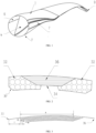
- the lightweight spar cap is groove-shaped as a whole, and includes supporting portions 32 located on two wings of lightweight spar cap and an intermediate connecting portion 36 connecting the two supporting portions 32.
- One splicing surface formed by connecting supporting portion 32 and the intermediate connecting portion 36 is an integral plane.
- the shape of the integral plane is configured to be consistent with an inner side of an upper shell 1 or a lower shell 2 of the wind turbine blade for abutting.
- the other splicing surface formed by connecting supporting portion 32 and the intermediate connecting portion 36 is a groove-shaped discontinuous plane.
- a positioning groove 34 formed by the groove-shaped discontinuous plane is configured to be consistent with an end of a web 5 of the wind turbine blade for abutting and nesting.
- a cross section of the intermediate connecting portion 36 is in a trapezoidal shape.
- a reinforcing body of the intermediate connecting portion is formed by sequentially superimposing multiple layers of reinforcing fiber cloths from a trapezoidal upper base to a lower base.
- the cross section of the reinforcing body formed by superimposing the reinforcing fiber cloths finally presents a trapezoidal shape.
- the reinforcing fiber cloth is a carbon fiber cloth layer, and the carbon fiber cloth layers with equal widths are laid in a staggered manner to form the trapezoidal reinforcing body (shown in FIG. 3 ).
- the supporting portion 32 adopts a reinforcing material composed of one or more from the group consisting of balsa, polyvinyl chloride (PVC), polyethylene terephthalate (PET) and high-density polyethylene (HPE).
- a thickness of the supporting portion is greater than that of the intermediate connecting portion 36, and the supporting portion wraps a lateral side of the intermediate connecting portion 36 into an inverted trapezoidal groove (i.e. a positioning groove 34).
- the supporting portion 32 and the intermediate connecting portion 36 are integrally molded by resin infusion.
- An inclined surface 37 is provided at an outer corner of the supporting portion 32, and the inclined surface 37 is kept substantially parallel to the trapezoidal lateral side of the intermediate connecting portion 36.
- the inclined surface can form a smooth transition with the core material structure of the blade shell beside the spar cap in the height direction so as to avoid the formation of thickness steps.
- a method for manufacturing the lightweight spar cap for a wind turbine blade includes:
- a lightweight spar cap structure combination for a wind turbine blade includes a web 5 and two lightweight spar caps for the wind turbine blade.
- the lightweight spar caps for the wind turbine blade are concave spar caps, and the two concave spar caps include a pressure surface lightweight spar cap 3 and a suction surface lightweight spar cap 4.
- a longitudinal positioning structure is provided on one side of each of the pressure surface lightweight spar cap 3 and the suction surface lightweight spar cap 4. Double ends of the web 5 are respectively connected with the positioning structures of the pressure surface lightweight spar cap 3 and the suction surface lightweight spar cap 4 through a positioning matching structure, and are fixedly connected with the pressure surface lightweight spar cap 3 and the suction surface lightweight spar cap 4 as a whole.
- the positioning structure and the positioning matching structure adopt a groove matching positioning mode.
- the positioning structure is configured as a positioning groove 34
- the positioning matching structure is configured as an insert that fits with the positioning groove 34.
- the positioning groove 34 is a trapezoidal groove respectively provided on the pressure surface lightweight spar cap 3 and the suction surface lightweight spar cap 4, and the insert is a base plate.
- the base plate includes the upper base plate 51 and the lower base plate 52 which are respectively provided at double ends of the web 5.
- the web 5 is I-shaped, and includes the upper base plate 51 and the lower base plate 52 that are located on upper and lower ends and matched with the trapezoidal groove.
- the pressure surface lightweight spar cap 3 is provided with an upper positioning groove 31, and the suction surface lightweight spar cap is provided with a lower positioning groove 41.
- An inner shaped surface of the upper positioning groove 31 and an inner shaped surface of the lower positioning groove 41 are matched with shaped surfaces of the upper base plate 51 and the lower base plate 52 respectively.
- the upper base plate 51 and the lower base plate 52 are respectively located in the upper positioning groove 31 of the pressure surface lightweight spar cap 3 and the lower positioning groove 41 of the suction surface lightweight spar cap 4.
- the present disclosure further provides a lightweight wind turbine blade.
- the lightweight wind turbine blade includes an upper shell 1, a lower shell 2 and the lightweight spar cap structure combination.
- One end of the lightweight spar cap structure combination for the wind turbine blade is connected with the upper shell 1, and the other end thereof is connected with the lower shell 2.
- the lightweight spar cap structure combination for the wind turbine blade is fixedly connected with the upper shell 1 and the lower shell 2 as a whole.
- the lightweight spar cap structure combination of the wind turbine blade in this embodiment is substantially the same as that of Embodiment 1, except that there are two lightweight spar cap structure combinations provided in this embodiment. Specifically, as shown in FIG. 11 , butt joints on both sides of the upper shell 1 and the lower shell 2 respectively form the leading edge 6 and the trailing edge 7 of the wind turbine blade.
- one lightweight spar cap structure combination for the wind turbine blade is exactly the same as that in Embodiment 1, which includes a web 5 and two lightweight spar caps described in Embodiment 1; a trailing edge web 8 is further provided in a trailing edge chamber formed by the web 5 and the trailing edge 7.
- the structure and composition of the trailing edge web 8 are substantially the same as the lightweight spar cap structure combination for the wind turbine blade in Embodiment 1, except that the height and shape are slightly different. As shown in FIG.
- a starting point 61 of the trailing edge web 8 along a length direction of the blade is provided in a region that contributes 12% to 15% to a total length of the blade from a blade root 63
- an end point 62 of the trailing edge web 8 along the length direction of the blade is provided in a region that contributes 57% to 60% to the total length of the blade from the blade root 63.
- a height of the trailing edge web is smaller than that of the web 5, and the trailing edge web is substantially parallel to the web 5.
- the present disclosure provides another lightweight spar cap for a wind turbine blade.
- the overall structure, material and manufacturing method of the lightweight spar cap are the same as those in Embodiments 1 and 2, except that the lightweight spar cap is provided with a V-shaped groove.
- a lightweight spar cap structure combination includes a web 5 and two lightweight spar caps as described in the above embodiment.
- the lightweight spar caps for the wind turbine blade are concave spar caps, and the two concave spar caps include a pressure surface lightweight spar cap 3 and a suction surface lightweight spar cap 4.
- a longitudinal positioning structure is provided on one side of each of the pressure surface lightweight spar cap 3 and the suction surface lightweight spar cap 4. Double ends of the web 5 are respectively connected with the positioning structures of the pressure surface lightweight spar cap 3 and the suction surface lightweight spar cap 4 through a positioning matching structure, and are fixedly connected with the pressure surface lightweight spar cap 3 and the suction surface lightweight spar cap 4 as a whole.
- the positioning structure and the positioning matching structure adopt a groove matching positioning mode.
- the positioning structure is configured as a positioning groove 34
- the positioning matching structure is configured as an insert that fits with the positioning groove 34.
- the positioning groove 34 is a V-shaped groove respectively provided on the pressure surface lightweight spar cap 3 and the suction surface lightweight spar cap 4, and the insert is a positioning rib respectively provided at double ends of the web 5.
- the web 5 is I-shaped, and includes the upper base plate 51 and the lower base plate 52 that are located on upper and lower ends and matched with the trapezoidal groove.
- the upper base plate 51 and the lower base plate 52 are respectively provided with a positioning rib.
- An upper top surface of the upper base plate 51 and a lower bottom surface of the lower base plate 52 are respectively provided with a longitudinal upper positioning rib 53 and a lower positioning rib 54.
- An inner shaped surface of the upper positioning groove 31 and an inner shaped surface of the lower positioning groove 41 are matched with outer shaped surfaces of the upper positioning rib 53 and the lower positioning rib 54 respectively.
- the upper positioning rib 53 of the upper base plate 51 of the I-shaped web 5 is provided in the upper positioning groove 31 of the pressure surface lightweight spar cap 3.
- the lower positioning rib 54 of the lower base plate 52 of the I-shaped web 5 is provided in the lower positioning groove 41 of the suction surface lightweight spar cap 4.
- the present disclosure further provides a lightweight wind turbine blade.
- the lightweight wind turbine blade includes an upper shell 1, a lower shell 2 and the lightweight spar cap structure combination as described in the above embodiment.
- One end of the lightweight spar cap structure combination for the wind turbine blade is connected with the upper shell 1, and the other end thereof is connected with the lower shell 2.
- the lightweight spar cap structure combination for the wind turbine blade is fixedly connected with the upper shell 1 and the lower shell 2 as a whole.
- the manufacturing method of the lightweight spar cap for the wind turbine blade in this embodiment is substantially the same as that of Embodiment 1, except that the shape of the groove is slightly different.
- the upper shell 1 and the lower shell 2 of the wind turbine blade use a compressive and shear resistant composite material that is able to withstand multi-directional pressure and shear force.
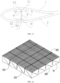
- the composite material includes a core material and glass fiber fabrics 86 adhered on upper and lower surfaces of the core material.
- the core material uses a sandwich panel 9 as a support. A path is formed in the sandwich panel to place a fiber bundle.
- a vertical fiber column 81, a diagonal fiber column 82, a longitudinal fiber rib 83 and a transverse fiber rib 84 are formed in the sandwich panel 9 by a dipping process.
- the diagonal fiber column 82, the longitudinal fiber rib 83 and the transverse fiber rib 84 form a lattice type fence 85 that is vertically and horizontally interwoven and integrally bonded in the sandwich panel 9.
- the glass fiber fabrics 86 are adhered on the upper and lower surfaces of the sandwich panel 9 before dipping, and the glass fiber fabrics 86 are bonded with the vertical fiber column 81 and the lattice type fence 85 to form an integral structure.
- the vertical fiber column 81 directly resists a positive pressure exerted on the sandwich panel 9 in the structure.
- the pressure exerted on the panel also includes other pressure in various directions. Therefore, the diagonal fiber column 82 is provided in the structure.
- the longitudinal fiber rib 83 and the transverse fiber rib 84 bond with all the diagonal fiber columns 82 to an integral frame through a glue. They enhance the stability of each diagonal fiber column 82 in case of pressure, and significantly enhance the compressive performance of the sandwich panel 9 against pressure in all directions.
- the longitudinal fiber rib 83 and the transverse fiber rib 84 also significantly enhance the tensile performance of the sandwich panel 9 in the horizontal direction.
- the lattice type fence 85 is actually only a description of a part of the mechanical overall structure constructed in the sandwich panel 9.
- the diagonal fiber column 82, the longitudinal fiber rib 83 and the transverse fiber rib 84 form a lattice type fence 85 that is vertically and horizontally interwoven and integrally bonded in the sandwich panel 9. That is, two transversely adjacent diagonal fiber columns 82 in the sandwich panel 9 are bonded to two sides of the longitudinal fiber rib 83 in an X shape, and two longitudinally adjacent diagonal fiber columns 82 in the sandwich panel 9 are bonded to two sides of the transverse fiber rib 84 in an X shape. Meanwhile, the adjacent longitudinal fiber rib 83 and transverse fiber rib 84 are bonded together.
- multiple orthogonal longitudinal slits and transverse slits are equally spaced on the sandwich panel, and the sandwich panel is divided into a number of sandwich squares connected at the bottom.
- a vertical hole is drilled downward on the sandwich square, and diagonal holes are drilled downward along front, left, back and right sides of the sandwich square respectively.
- the sandwich panel 9 used is composed of any one or more of balsa, PVC, PET and HPE. These materials are easy to cut and perforate, and various frames may be built in the panel for support. In addition, these materials are light in weight, and after being constructed into a compressive integral structure, they are sufficient to become qualified sandwich materials for the root region of the wind turbine blade shell.
- the glass fiber fabric is made of a carbon fiber-glass fiber composite material, which is a hybrid design of a carbon fiber and a glass fiber in a mass ratio of (10-90):(10-90).
- the vertical fiber column 81, the diagonal fiber column 82, the longitudinal fiber rib 83 and the transverse fiber rib 84 are formed in the panel.
- the diagonal fiber column 82, the longitudinal fiber rib 83 and the transverse fiber rib 84 form a lattice type fence 85 that is vertically and horizontally interwoven and integrally bonded in the sandwich panel.
- the glass fiber fabrics 86 on the upper and lower surfaces are bonded with the vertical fiber column 81 and the lattice type fence 85 to form an integral frame. All of the above processes are completed by one-time dipping. Specifically, holes and slits are provided in the sandwich panel 9 to place the fiber bundles, adhere the glass fiber fabrics 86 and implement dipping and curing to form the integral structure.
- the wind turbine blade of the above embodiments further includes a lightweight lightning protection system.
- the lightning protection system adopts a carbon fiber cloth layer.
- the lightning protection system is composed of a carbon fiber cloth layer 91 wrapping a surface of the upper shell 1 and the lower shell 2, a metal belt 93, a down conductor 96 that is connected with a wind turbine lightning protection system, a doubling device 95 and a wire doubling device 94.
- the carbon fiber cloth layer 91 conducts a lightning current to the metal belt 93.
- the metal belt 93 is connected with the down conductor 96 through a wire.
- the upper shell 1 and the lower shell 2 are provided with the wind turbine blade lightning protection system of this embodiment.
- the carbon fiber cloth layer 91 covers outer surfaces of the upper shell 1 and the lower shell 2, and is laid from a blade tip to a blade root.
- a width of the carbon fiber cloth layer 91 depends on a lightning current carrying capacity of a carbon fiber material, and a minimum requirement is that the lightning current passes through the carbon fiber cloth layer 91 without damaging the carbon fiber cloth layer.
- the carbon fiber cloth layer 91 plays a dual role of structural bearing and lightning current conduction in the wind turbine blade of this embodiment.
- the carbon fiber cloth layer 91 and the metal belt 93 are connected with the blade by integral infusion.
- a connection point of the metal belt and the carbon fiber cloth along the length direction of the blade is located in a region that contributes 30% to the total length of the wind turbine blade from the blade root.
- the carbon fiber cloth layer 91 conducts the lightning current to two layers of metal belts 93 through two additional carbon fiber cloth layers 92.
- the carbon fiber cloth layer 91 is superimposed with an additional carbon fiber cloth layer 92.
- Each carbon fiber cloth layer 92 is alternately superimposed with each layer of metal belt 93, with the same superimposed area at each layer.
- the carbon fiber cloth layer 91 and the additional carbon fiber cloth layer 92 completely cover the metal belt 93.
- the ability of the superimposed carbon fiber cloth layers to pass current reaches a lightning current standard of 200 KA.
- the lightning is dispersed to the multiple layers of metal belts 93 through the multiple additional carbon fiber cloth layer 92 and is finally conducted to the down conductor 96.
- the multilayer alternate superimposed design of the additional carbon fiber cloth layers 92 and metal belts 93 reduces the sudden change of resistance from the carbon fiber cloth layers 91 to the metal belts 93.
- this design reduces the damage of the lightning current to the carbon fiber near the carbon fiber cloth layer.
- the carbon fiber cloth layer 91 is connected to the surface of the blade shell by integral infusion. During the infusion process, the carbon fiber cloth layer 91 is laid on the mold, and the resin is then infused, such that the resin and the inner side of the carbon fiber cloth layer 91 form an integral structure. The outer side of the carbon fiber cloth layer 91 is not wrapped with the resin, and is exposed to conduct lightning.
- the metal belt 93 passes through the upper shell 1 and the lower shell 2 and extends into the blade chamber to be twisted into a strand, and is connected with the wire through a doubling device 95.
- Upper and lower wires are connected with the down conductor 96 through a wire doubling device 94.
- the down conductor 96 is connected with the wind turbine lightning protection system at the blade root.
- the carbon fiber cloth layer is laid on the surface of the shell through infusion for air termination. It expands the air termination area, improves the air termination efficiency, and guides the lightning to the down conductor at the blade root.
- a method for manufacturing the lightweight wind turbine blade includes: assemble the upper shell 1, the lower shell 2, the pressure surface lightweight spar cap 3, the suction surface lightweight spar cap 4 and the web 5 as a whole. Specifically:
Landscapes
- Engineering & Computer Science (AREA)
- Mechanical Engineering (AREA)
- Chemical & Material Sciences (AREA)
- Composite Materials (AREA)
- Life Sciences & Earth Sciences (AREA)
- Sustainable Development (AREA)
- Sustainable Energy (AREA)
- Combustion & Propulsion (AREA)
- General Engineering & Computer Science (AREA)
- Wind Motors (AREA)
Description
- The present disclosure belongs to the technical field of wind power generation, and in particular relates to a lightweight spar cap with a concave structure for a wind turbine blade and a manufacturing method thereof.
- The wind turbine mainly relies on the blade to capture wind energy. The length of the blade directly affects the ability of the wind turbine to capture wind energy and the output power of the wind turbine. The blade is increasingly long due to the performance improvement requirement. When the blade is extended, the weight increases exponentially, and the center of gravity shifts to the tip of the blade, resulting in a significant increase in gravity fatigue load and centrifugal load, reducing the reliability of the blade and the wind turbine, and increasing the cost. Therefore, the promotion of the blade extension design technology requires a lightweight blade.
- Document
US 2018/238301 A1 discloses a shear web for a rotor blade of a wind turbine and a method of manufacturing and assembling same. The rotor blade generally includes an upper shell member having an upper spar cap configured on an internal surface thereof and a lower shell member having a lower spar cap configured on an internal surface thereof. Further, the shear web extends between the spar caps along a longitudinal length of the blade. In addition, the shear web includes first and second outer pultruded layers at least partially encompassing a core material, wherein end portions of the first and second outer pultruded layers form compressed flanges at opposing ends of the shear web. - Document
CN112912235B discloses a spar cap having a profile for guiding and receiving a shear web for wind turbine blade. Particularly, this disclosure provides a pultruded spar cap having a bond gap feature to maintain a uniform space for distribution of bonding paste between the spar cap and shear web. Also, the spar cap is formed with locating features which guide and receive placement of the shear web. - Document
CN102889169B discloses a wind turbine blade having upper and lower shell members with a respective spar cap configured on an internal face of the shell members. A shear web extends between the spar caps along a longitudinal length of the blade. A connection assembly is configured between the transverse ends of the shear web and the spar caps. The connection assembly includes a spacer member configured on the spar cap. A male/female engagement interface is defined between transverse end of the shear web and the spacer member, and includes an axial extension length to accommodate for variances in shear web length. - Document
CN101825057B discloses a blade of a wind turbine having an improved spar cap. The spar cap includes at least one trench extending in a substantially span-wise direction in at least a portion of the spar cap. At least one shear web is connected to the spar cap. At least a portion of the shear web is positioned within the trench of the spar cap. - Document
CN112512784B discloses a wind turbine blade mould extending longitudinally in a spanwise direction and transversely in a chordwise direction and a spar cap placed in the mould. The spar cap comprises a plurality of strips extending longitudinally in the spanwise direction and arranged side-by-side in the chordwise direction, said strips comprising one or more intermediate strips arranged between peripheral strips which are inclined relative to the intermediate strips. A shear web comprising a flange extending longitudinally in the spanwise direction is provided, the flange comprising a base defining a primary bonding surface. A chordwise width of the primary bonding surface corresponds substantially to a chordwise width of the intermediate strips of the spar cap. The primary bonding surface of the flange is bonded to the one or more intermediate strips of the spar cap. - Document
CN111868374A discloses a method for assembling a shear web assembly of a wind turbine including providing at least one spar cap. The method also includes forming a spar connecting member of a thermoplastic material via additive manufacturing. Further, the method includes securing the spar connecting member to the spar cap. Moreover, the method includes providing a shear web, forming a web connecting member of a thermoplastic material via additive manufacturing, and securing the web connecting member at a first end of the shear web. In addition, the method includes interconnecting the web connecting member and the spar connecting member at a joint. Thus, the method further includes heating the joint to secure the web connecting member and the spar connecting member together. - The traditional blade has the following disadvantages. 1) The spar cap structure is rectangular, and the material utilization of the rectangular spar cap under the same bending rigidity cannot be maximized. 2) When the upper shell and the lower shell are assembled together, it is necessary to draw lines according to the theoretical web position, and glue claws or wooden blocks at the corresponding positions for positioning. However, affected by the measurement method and the operator, the positioning of the web is still not accurate. In addition, since it is necessary to bond and remove the claws or wood blocks, the content of the work is greatly increased. Meanwhile, the bonding structure increases the weight of the blade. 3) The double/triple-web structure is heavy. 4) The panel and the core material are heavy and have poor mechanical endurance. 5) The lightning protection system includes a copper wire, a glass fiber cloth for fixing the copper wire, a copper base, a glass fiber reinforced plastic support, an air termination device and an adhesive glue, etc., which has a complex structure and a large weight.
- Therefore, it is urgently necessary for those skilled in the research of lightweight blade engineering to comprehensively consider the above factors to reduce the weight of the wind turbine blade.
- In order to overcome the shortcomings of the prior art and to realize a lightweight wind turbine blade, the present disclosure provides a lightweight spar cap with a concave structure for a wind turbine blade and a manufacturing method thereof.
- To solve the above technical problem, the present disclosure proposes the following technical solution:
- The present disclosure provides a lightweight spar cap with a concave structure for a wind turbine blade. The lightweight spar cap is groove-shaped as a whole, and includes supporting portions located on two wings of the lightweight spar cap and an intermediate connecting portion connecting the two supporting portions;
- one splicing surface formed by connecting the supporting portion and the intermediate connecting portion is an integral plane; the shape of the integral plane is configured to be consistent with an inner side of an upper shell or a lower shell of the wind turbine blade for abutting;
- the other splicing surface formed by connecting the supporting portion and the intermediate connecting portion is a groove-shaped discontinuous plane; a positioning groove formed by the groove-shaped discontinuous plane is configured to be consistent with an end of a web of the wind turbine blade for abutting and nesting.
- Preferably, a cross section of the intermediate connecting portion may be in a trapezoidal shape; a reinforcing body of the cross section may be formed by sequentially superimposing multiple layers of reinforcing fiber cloth from an upper base to a lower base of a trapezoid; the cross section of the reinforcing body formed by superimposing the reinforcing fiber cloths may present a trapezoidal shape.
- The reinforcing body formed by superimposing the reinforcing fiber cloths provides rigidity and strength for the concave spar cap. The intermediate connecting portion serving as the main bearing structure is a trapezoidal structure, which provides rigidity and strength for the lightweight spar cap. Compared with a rectangular spar cap, the lightweight spar cap has a larger area moment. Under the same bending rigidity, the lightweight spar cap is lighter than the rectangular spar cap, which can achieve the purpose of reducing the weight of the blade.
- Preferably, the reinforcing fiber cloth may be a carbon fiber cloth layer, and the reinforcing body may be made of carbon fiber cloths with equal widths in staggered layers to form a trapezoidal cross section.
- The intermediate connecting portion made of carbon fiber cloth layers with equal widths is tidier, making the processing easier.
- Preferably, a thickness of the supporting portion may be greater than that of the intermediate connecting portion, and the supporting portion may wrap a lateral side of the intermediate connecting portion into an inverted trapezoidal groove. The structure of the supporting portion is designed according to the intermediate connecting portion, which is helpful for the combination of the internal structure of the spar cap, improves the stability of the lightweight spar cap, and facilitates the formation of a concave groove to locate the web.
- Preferably, an inclined surface may be provided at an outer corner of the supporting portion, and the inclined surface may be kept substantially parallel to the trapezoidal lateral side of the intermediate connecting portion. The inclined surface at the corner facilitates a smooth transition with the adjacent structure, and avoids the formation of thickness steps, which cause stress concentration of the blade. The supporting portion, the intermediate connecting portion and the adjacent structure are integrated by resin bonding.
- Preferably, the supporting portion may adopt a reinforcing material composed of one or more from the group consisting of balsa, polyvinyl chloride (PVC), polyethylene terephthalate (PET) and high-density polyethylene (HPE); the supporting portion and the intermediate connecting portion may be integrally molded by resin infusion.
- The supporting portion and the intermediate connecting portion are connected through resin infusion, which avoids the need to use an additional glue and to reserve a bonding gap, and achieves simple molding and convenient operation. The commonly used materials for the intermediate connecting portion and the supporting portion include a resin. On this basis, through resin infusion molding, the adhesion between the resin and the core material and the reinforcing layer is improved, thereby enhancing the strength of the lightweight spar cap.
- Under the same technical concept, the present disclosure further provides a method for manufacturing the lightweight spar cap with a concave structure for a wind turbine blade. The method includes the following steps:
- (1) laying the reinforcing material of the intermediate connecting portion on a spar cap mold, such that the reinforcing body of the intermediate connecting portion presents a trapezoidal shape, and the lower base of the trapezoidal reinforcing body abuts against a surface of the spar cap mold;
- (2) placing the reinforcing material of the supporting portion on both sides of the reinforcing body of the intermediate connecting portion, such that the reinforcing material of the supporting portion wraps the trapezoidal lateral side of the reinforcing body to form the positioning groove that is able to match with the end of the web of the wind turbine blade later, thereby obtaining a composite body of reinforcing materials; and
- (3) subjecting the composite body of reinforcing materials obtained in the above step to an integral resin infusion process, to finally obtain the lightweight spar cap for the wind turbine blade.
- Preferably, the laying the reinforcing material of the intermediate connecting portion may specifically include: laying carbon fiber cloth layers with equal widths in a staggered manner, where each carbon fiber cloth layer may have a size of L; a first layer may have a distance of D from a left end of the spar cap mold, a second layer may have a distance of D+L from the left end of the spar cap mold, and so on, until an (N+1)-th layer may have a distance of D from a right end of the spar cap mold. In this way, the laying of the intermediate connecting portion is completed. The width of the carbon fiber cloth is denoted as A. By laying the carbon fiber cloth layers in a staggered manner, the trapezoidal structure required for the intermediate connecting portion is formed. Compared with an ordinary panel, the trapezoidal structure reduces the weight of the spar cap structure.
- The spar cap mold is provided with a diversion system and an air extraction system, and it is continuously heated during the production process. The diversion system and the air extraction system are designed to facilitate the introduction of the resin, and the air extraction system exerts a vacuum pressure to pump the resin into the spar cap mold. The heating temperature is program-controlled, which is helpful for the curing and shaping of the intermediate connecting portion, the supporting portion and the resin.
- Under the same technical concept, the present disclosure further provides a lightweight spar cap structure combination for a wind turbine blade. The lightweight spar cap structure combination includes a web and two lightweight spar caps for the wind turbine blade, where the lightweight spar caps for the wind turbine blade are concave spar caps, and the two concave spar caps include a pressure surface lightweight spar cap and a suction surface lightweight spar cap;
a positioning structure is provided on one side of each of the pressure surface lightweight spar cap and the suction surface lightweight spar cap; double ends of the web are respectively connected with the positioning structures of the pressure surface lightweight spar cap and the suction surface lightweight spar cap through a positioning matching structure, and are fixedly connected with the pressure surface lightweight spar cap and the suction surface lightweight spar cap as a whole. - Preferably, the positioning structure and the positioning matching structure may adopt a groove matching positioning mode; one of the positioning structure and the positioning matching structure may be configured as a positioning groove, and the other thereof may be configured as an insert that fits with the positioning groove.
- Preferably, the groove matching positioning mode may be any one of the following:
- the positioning groove is a trapezoidal groove respectively provided on the pressure surface lightweight spar cap and the suction surface lightweight spar cap, and the insert is an upper base plate and a lower base plate which are respectively provided at double ends of the web and matched with the trapezoidal groove; or
- the positioning groove is a V-shaped groove respectively provided on the pressure surface lightweight spar cap and the suction surface lightweight spar cap, and the insert is a positioning rib respectively provided at double ends of the web.
- Preferably, the web may be in an I-shape, and may include an upper base plate and a lower base plate located at upper and lower ends and matched with the trapezoidal groove.
- Preferably, the pressure surface lightweight spar cap and the suction surface lightweight spar cap may be respectively groove-shaped, and may include supporting portions located on two wings of the lightweight spar cap and an intermediate connecting portion connecting the two supporting portions;
- one splicing surface formed by connecting the supporting portion and the intermediate connecting portion may be an integral plane; the shape of the integral plane may be configured to be consistent with an inner side of an upper shell or a lower shell of the wind turbine blade for abutting;
- the other splicing surface formed by connecting the supporting portion and the intermediate connecting portion may be a groove-shaped discontinuous plane; a positioning groove formed by the groove-shaped discontinuous plane may be configured to be consistent with an end of a web of the wind turbine blade for abutting and nesting.
- Under the same technical concept, the present disclosure further provides a lightweight wind turbine blade. The lightweight wind turbine blade includes an upper shell, a lower shell and the lightweight spar cap structure combination, where one end of the lightweight spar cap structure combination for the wind turbine blade is connected with the upper shell, and the other end thereof is connected with the lower shell; the lightweight spar cap structure combination for the wind turbine blade is fixedly connected with the upper shell and the lower shell as a whole; double ends of the upper shell and the lower shell are correspondingly connected to form a leading edge and a trailing edge respectively.
- Preferably, in the lightweight spar cap structure combination, a trailing edge web may be provided in a trailing edge chamber defined by the web and the trailing edge.
- Preferably, a starting point of the trailing edge web along a length direction of the blade may be provided in a region that contributes 12% to 15% to a total length of the blade from a blade root, and an end point of the trailing edge web along the length direction of the blade may be provided in a region that contributes 57% to 60% to the total length of the blade from the blade root; a height of the trailing edge web may be smaller than that of the web, and the trailing edge web is substantially parallel to the web.
- Preferably, the upper shell and the lower shell may be made of a compressive and shear resistant composite material; the composite material may include a core material and glass fiber fabrics adhered on upper and lower surfaces of the core material; the core material may use a sandwich panel as a support; a path may be formed in the sandwich panel to place a fiber bundle; a vertical fiber column, a diagonal fiber column, a longitudinal fiber rib and a transverse fiber rib may be formed in the sandwich panel by a dipping process; the diagonal fiber column, the longitudinal fiber rib and the transverse fiber rib may form a lattice type fence that is vertically and horizontally interwoven and integrally bonded in the sandwich panel; the glass fiber fabrics adhered on the upper and lower surfaces of the sandwich panel may be bonded with the vertical fiber column and the lattice type fence to form an integral structure. The core material of the overall structure constructed by the glass fiber fabric, the vertical fiber column and the lattice type fence has strong compressive and shear resistant properties, which improves the load-bearing capacity and strength of the shell of the wind turbine blade.
- Preferably, the compressive and shear resistant core material may be able to withstand multi-directional pressure and shear force; the sandwich panel may be made of any one or more from the group consisting of balsa, PVC, PET and HPE; the shell of the wind turbine blade may adopt a carbon fiber-glass fiber composite material, which may be a hybrid design of carbon fiber and glass fiber in a mass ratio of (10-90):(10-90).
- Preferably, the lightweight wind turbine blade may further include a lightning protection system; the lightning protection system may include a carbon fiber cloth layer wrapping a surface of the upper shell and/or the lower shell, at least one layer of metal belt and a down conductor that may be connected with a wind turbine lightning protection system; the carbon fiber cloth layer may conduct a lightning current to the metal belt; the metal belt may be connected with the down conductor through a wire.
- The present disclosure applies the carbon fiber cloth layer to the lightning protection system. The carbon fiber cloth is laid on the surface of the blade and connected to the root wire of the lightning protection system through the down conductor. When the blade is struck by lightning, the lightning current is conducted to the wind turbine lightning protection system. The carbon fiber cloth can bear the structural load, and can also conduct the lightning current to the down conductor, thereby assuming the dual role of conductor and load-bearing structure in the blade lightning protection system. It can effectively reduce the weight of the blade lightning protection system, increase the range of air termination, and improve the air termination efficiency of the blade, thereby effectively protecting the blade.
- Preferably, the carbon fiber cloth layer may conduct the lightning current to the at least one layer of metal belt through at least one additional carbon fiber cloth layer; a width of the carbon fiber cloth layer may depend on a lightning current carrying capacity of a carbon fiber material, and a minimum requirement may be that the lightning current passes through the carbon fiber cloth layer without damaging the carbon fiber cloth layer.
- Preferably, there may be multiple additional carbon fiber cloth layers and multiple layers of metal belts; the multiple additional carbon fiber cloth layers and the multiple layers of metal belts may be alternately arranged, such that the lightning may be dispersed to the multiple layers of metal belts through the multiple additional carbon fiber cloth layers and may be finally conducted to the down conductor.
- Multiple additional carbon fiber cloth layers and metal belts are arranged between the carbon fiber cloth layer and the down conductor, and the additional carbon fiber cloth layers alternately superimposed with the carbon fiber cloth layers and the metal belts to reduce the sudden change of resistance from the carbon fiber cloth layers to the metal belts. When the lightning current is conducted from the carbon fiber cloth layer to the down conductor, this design reduces the damage of the lightning current to the carbon fiber near the carbon fiber cloth layer, and reduces the damage to the wind turbine blade using the carbon fiber cloth lightning protection system.
- Preferably, a superimposed area of each additional carbon fiber cloth layer may be the same, and each additional carbon fiber cloth layer completely covers the metal belt. The ability of the superimposed carbon fiber cloth layers to pass current reaches a lightning current standard of 200 KA.
- Preferably, the carbon fiber cloth layer may be laid from a blade tip to the blade root; a connection point of the metal belt and the carbon fiber cloth along the length direction of the blade may be located in a region that contributes 30% to the total length of the wind turbine blade from the blade root; the carbon fiber cloth layer and the metal belt may be connected with the blade by integral infusion.
- The wind turbine lightning protection system is mostly provided in the blade root. The down conductor and the wire are connected with the metal belt, and the connection point of the metal belt and the carbon fiber cloth is close to the blade root, so as to approach the lightning protection system, which can save the consumption of the down conductor and the wire, thereby reducing the overall weight of the lightning protection system.
- The wind turbine blade is narrow in the tip and wide in the root. The connection point of the metal belt and the carbon fiber cloth is provided close to the blade root, which provides a large operation space for mounting and for the arrangement of the additional carbon fiber layer, thereby facilitating the operation of the staff.
- Preferably, the metal belt may pass through the blade shell and extend into the blade chamber to be twisted into a strand, and may be connected with the wire through a doubling device; upper and lower wires may be connected with the down conductor through a wire doubling device; the down conductor may be connected with the wind turbine lightning protection system at the blade root.
- The carbon fiber cloth layer is laid on the surface of the shell through infusion for air termination. It expands the air termination area, improves the air termination efficiency, and guides the lightning to the down conductor at the blade root. Meanwhile, the gap reserved in the shell for the metal belt and the wire to pass through is filled by the integral infusion, so as to achieve a waterproof effect.
- Under the general technical concept, the present disclosure further provides a method for manufacturing a lightweight wind turbine blade. The method includes the following steps:
- step 1: respectively fixedly connecting a pressure surface lightweight spar cap and a suction surface lightweight spar cap, which are respectively provided with a positioning groove, with an upper shell and a lower shell as a whole;
- step 2: placing the suction surface lightweight spar cap fixedly connected with the lower shell as a whole upwards, and applying a structural glue to the positioning groove of the lower shell; lifting a web onto the suction surface lightweight spar cap, and inserting a lower base plate of the web into the positioning groove coated with the structural glue to realize the positioning and fixing of the web on the suction surface lightweight spar cap; and
- step 3: applying a structural glue to an outer surface of an upper base plate of the web, lifting the upper shell together with the pressure surface lightweight spar cap fixed with the upper shell above the web, lowering the upper shell and the pressure surface lightweight spar cap, inserting the upper base plate of the web into the positioning groove of the pressure surface lightweight spar cap, and fixedly connecting the web with the pressure surface lightweight spar cap through the applied structural glue.
- Compared with the prior art, the present disclosure has the following beneficial effects;
- 1. In the lightweight spar cap with a concave structure for a wind turbine blade and the manufacturing method thereof proposed by the present disclosure, the spar cap is a lightweight concave spar cap, which has a trapezoidal main bearing structure composed of fiber reinforcing layers. Compared with a rectangular spar cap, the lightweight spar cap has a larger area moment. Under the same bending rigidity, the lightweight spar cap is lighter than the rectangular spar cap, which can achieve the purpose of reducing the weight of the blade.
- 2. In the wind turbine blade proposed by the present disclosure, the wind turbine blade with a concave structure is fixed with the lightweight spar cap and the web, and an integrated positioning groove is provided on the lightweight spar cap. During assembling, the web can be accurately and stably provided on the lightweight spar cap, which facilitates the further assembly of the spar cap and the shell. There is no need to temporarily add any auxiliary facilities, making the entire assembly process simple and efficient.
- 3. In the lightweight spar cap structure combination for a wind turbine blade proposed by the present disclosure, the combination of the single web and the lightweight spar cap structure reduces the weight of the web to achieve a lightweight wind turbine blade.
- 4. In the lightweight wind turbine blade proposed by the present disclosure, the web is combined with the small web at the trailing edge, and the weight of the web is greatly reduced compared with the traditional wind turbine blade. The small web at the trailing edge increases the strength of the trailing edge, and reduces the bonding width of the trailing edge, thereby achieving the purpose of reducing the weight of the blade.
- 5. In the lightweight wind turbine blade proposed by the present disclosure, a special compressive and shear resistant core material is used, and a compressive integral structure capable of withstanding multi-directional pressure is constructed inside and outside the core material, which improves the strength and stability of the blade.
- 6. In the lightweight wind turbine blade proposed by the present disclosure, the carbon fiber cloth is applied to the lightning protection system. When the blade is struck by lightning, the lightning current is conducted to the wind turbine lightning protection system. The carbon fiber cloth can bear the structural load, and can also conduct the lightning current to the down conductor, thereby assuming the dual role of conductor and load-bearing structure in the blade lightning protection system. Such a design can reduce the weight of the blade lightning protection system, and can effectively protect the blade.
- To describe the technical solutions in the embodiments of the present disclosure or in the prior art more clearly, the following briefly describes the accompanying drawings required for describing the embodiments or the prior art. Apparently, the accompanying drawings in the following description merely show some embodiments of the present disclosure, and a person of ordinary skill in the art may still derive other accompanying drawings from these accompanying drawings without creative efforts.
-
FIG. 1 is an overall external view of a wind turbine blade. -
FIG. 2 is a cross-sectional view of a lightweight spar cap. -
FIG. 3 is a schematic diagram of reinforcing fiber cloths laid on the lightweight spar cap. -
FIG. 4 is a cross-sectional view of a lightweight spar cap ofEmbodiment 1 connected with a blade shell. -
FIG. 5 is a cross-sectional view of a web ofEmbodiment 1. -
FIG. 6 is a cross-sectional view of a lightweight spar cap structure combination ofEmbodiment 1 assembled with a wind turbine blade shell. -
FIG. 7 is a cross-sectional view of a lightning protection system of the wind turbine blade ofEmbodiment 1. -
FIG. 8 is a lateral external view of a wind turbine blade ofEmbodiment 1. -
FIG. 9 is a connection diagram of a carbon fiber cloth layer and a down conductor inEmbodiment 1. -
FIG. 10 is a diagram of a connection section of a carbon fiber cloth layer and a metal belt inEmbodiment 1. -
FIG. 11 is a cross-sectional view of a wind turbine blade ofEmbodiment 2. -
FIG. 12 is a schematic diagram of a trailing edge web on a side of the wind turbine blade inEmbodiment 2. -
FIG. 13 is a cross-sectional view of a lightweight spar cap ofEmbodiment 3 connected with a wind turbine blade shell. -
FIG. 14 is a cross-sectional view of a web ofEmbodiment 3. -
FIG. 15 is a cross-sectional view of a lightweight spar cap structure combination ofEmbodiment 3 assembled with a wind turbine blade shell. -
FIG. 16 is a schematic diagram of a compressive panel. -
FIG. 17 is a schematic diagram of a fiber structure inside the panel. - Reference Numerals: 1. upper shell; 2. lower shell; 3. pressure surface lightweight spar cap; 4. suction surface lightweight spar cap; 5. web; 6. leading edge; 7. trailing edge; 8. trailing edge web; 9. sandwich panel; 31. upper positioning groove; 41. lower positioning grove; 32. supporting portion; 33. left end of spar cap mold; 34. positioning groove; 35. right end of spar cap mold; 36. intermediate connecting portion; 37. inclined surface; 51. upper base plate; 52. lower base plate; 53. upper positioning rib; 54. lower positioning rib; 61. starting point; 62. end point; 63. blade root; 81. vertical fiber column; 82. diagonal fiber column; 83. longitudinal fiber rib; 84. transverse fiber rib; 85. lattice type fence; 86. glass fiber fabric; 91. carbon fiber cloth layer; 92. additional carbon fiber cloth layer; 93. metal belt; 94. wire doubling device; 95. doubling device; 96. down conductor.
- In order to facilitate the understanding of the present disclosure, the present disclosure is described in detail below in conjunction with the accompanying drawings of the specification and the preferred embodiments, but the protection scope of the present disclosure is not limited to the following specific embodiments.
- Unless otherwise defined, all professional terms used in the following have the same meaning as commonly understood by those skilled in the art. The terms used herein are only intended for the purpose of describing the specific embodiments, rather than to limit the protection scope of the present disclosure.
- Unless otherwise specified, the various raw materials, reagents, instruments and devices used in the present disclosure may be purchased from the market or may be manufactured by using existing methods.
- The present disclosure provides a lightweight spar cap for a wind turbine blade. As shown in
FIGS. 1 to 10 , the lightweight spar cap is groove-shaped as a whole, and includes supportingportions 32 located on two wings of lightweight spar cap and an intermediate connectingportion 36 connecting the two supportingportions 32. - One splicing surface formed by connecting supporting
portion 32 and the intermediate connectingportion 36 is an integral plane. The shape of the integral plane is configured to be consistent with an inner side of anupper shell 1 or alower shell 2 of the wind turbine blade for abutting. - The other splicing surface formed by connecting supporting
portion 32 and the intermediate connectingportion 36 is a groove-shaped discontinuous plane. Apositioning groove 34 formed by the groove-shaped discontinuous plane is configured to be consistent with an end of aweb 5 of the wind turbine blade for abutting and nesting. - A cross section of the intermediate connecting
portion 36 is in a trapezoidal shape. A reinforcing body of the intermediate connecting portion is formed by sequentially superimposing multiple layers of reinforcing fiber cloths from a trapezoidal upper base to a lower base. The cross section of the reinforcing body formed by superimposing the reinforcing fiber cloths finally presents a trapezoidal shape. The reinforcing fiber cloth is a carbon fiber cloth layer, and the carbon fiber cloth layers with equal widths are laid in a staggered manner to form the trapezoidal reinforcing body (shown inFIG. 3 ). The supportingportion 32 adopts a reinforcing material composed of one or more from the group consisting of balsa, polyvinyl chloride (PVC), polyethylene terephthalate (PET) and high-density polyethylene (HPE). A thickness of the supporting portion is greater than that of the intermediate connectingportion 36, and the supporting portion wraps a lateral side of the intermediate connectingportion 36 into an inverted trapezoidal groove (i.e. a positioning groove 34). The supportingportion 32 and the intermediate connectingportion 36 are integrally molded by resin infusion. - An
inclined surface 37 is provided at an outer corner of the supportingportion 32, and theinclined surface 37 is kept substantially parallel to the trapezoidal lateral side of the intermediate connectingportion 36. The inclined surface can form a smooth transition with the core material structure of the blade shell beside the spar cap in the height direction so as to avoid the formation of thickness steps. - In this embodiment, a method for manufacturing the lightweight spar cap for a wind turbine blade includes:
- (1) Clean a spar cap mold, provide a diversion system on a surface of the spar cap mold, and continuously heat the mold.
- (2) Lay carbon fiber cloths of equal widths in a staggered manner on a lower surface of the spar cap mold, as shown in
FIG. 3 , where each carbon fiber cloth layer has a size of 10 mm; a first layer has a distance of D, that is, 150 mm, from aleft end 33 of the spar cap mold, a second layer has a distance of D+L, that is, 160 mm, from theleft end 33 of the spar cap mold, and so on, until an eleventh layer has a distance of D, that is, 150 mm, from aright end 35 of the spar cap mold. In this way, the intermediate connectingportion 36 is formed into a trapezoidal laid structure, which has trapezoidal chamfers on two ends and a trapezoidal lower base abutting against the lower surface of the spar cap mold. - (3) Lay a reinforcing material of the supporting
portion 32 on both sides of the reinforcing body of the intermediate connectingportion 36, such that the reinforcing material of the supportingportion 32 wraps the trapezoidal lateral side of the reinforcing body of the intermediate connectingportion 36 to form thepositioning groove 34 that is able to match with anupper base plate 51 and alower base plate 52 on double ends of theweb 5 of the wind turbine blade later, thereby obtaining a composite body of reinforcing materials, where the positioning groove specifically includes anupper positioning groove 31 and alower positioning groove 41.
There is a small gap between an inner shaped surface of thepositioning groove 34 and upper and lower end surfaces of theweb 5, such that theweb 5 can be placed in theupper positioning groove 31 and thelower positioning groove 41 and a structural glue can be retained in this small gap. During and after assembly, theupper base plate 51 and thelower base plate 52 are respectively located in theupper positioning groove 31 and thelower positioning groove 41 and are fixed by the structural glue applied in advance. - (4) Provide a diversion system on an upper surface of the lightweight spar cap with the laid cloth layers, lay on the upper surface of the spar cap mold, and provide an air extraction system.
- (5) Exert a vacuum pressure of the air extraction system to introduce a resin, control a heating temperature of the mold, and perform curing.
- (6) Stop heating to complete the curing and shaping, demold and trim, to obtain the lightweight spar cap for a wind turbine blade.
- In this embodiment, a lightweight spar cap structure combination for a wind turbine blade includes a
web 5 and two lightweight spar caps for the wind turbine blade. The lightweight spar caps for the wind turbine blade are concave spar caps, and the two concave spar caps include a pressure surfacelightweight spar cap 3 and a suction surfacelightweight spar cap 4. - A longitudinal positioning structure is provided on one side of each of the pressure surface
lightweight spar cap 3 and the suction surfacelightweight spar cap 4. Double ends of theweb 5 are respectively connected with the positioning structures of the pressure surfacelightweight spar cap 3 and the suction surfacelightweight spar cap 4 through a positioning matching structure, and are fixedly connected with the pressure surfacelightweight spar cap 3 and the suction surfacelightweight spar cap 4 as a whole. - As shown in
FIG. 4 , in this embodiment, the positioning structure and the positioning matching structure adopt a groove matching positioning mode. Specifically, the positioning structure is configured as apositioning groove 34, and the positioning matching structure is configured as an insert that fits with thepositioning groove 34. - The
positioning groove 34 is a trapezoidal groove respectively provided on the pressure surfacelightweight spar cap 3 and the suction surfacelightweight spar cap 4, and the insert is a base plate. In this embodiment, the base plate includes theupper base plate 51 and thelower base plate 52 which are respectively provided at double ends of theweb 5. As shown inFIG. 5 , theweb 5 is I-shaped, and includes theupper base plate 51 and thelower base plate 52 that are located on upper and lower ends and matched with the trapezoidal groove. - As shown in
FIG. 6 , the pressure surfacelightweight spar cap 3 is provided with anupper positioning groove 31, and the suction surface lightweight spar cap is provided with alower positioning groove 41. An inner shaped surface of theupper positioning groove 31 and an inner shaped surface of thelower positioning groove 41 are matched with shaped surfaces of theupper base plate 51 and thelower base plate 52 respectively. Theupper base plate 51 and thelower base plate 52 are respectively located in theupper positioning groove 31 of the pressure surfacelightweight spar cap 3 and thelower positioning groove 41 of the suction surfacelightweight spar cap 4. - The present disclosure further provides a lightweight wind turbine blade. The lightweight wind turbine blade includes an
upper shell 1, alower shell 2 and the lightweight spar cap structure combination. One end of the lightweight spar cap structure combination for the wind turbine blade is connected with theupper shell 1, and the other end thereof is connected with thelower shell 2. The lightweight spar cap structure combination for the wind turbine blade is fixedly connected with theupper shell 1 and thelower shell 2 as a whole. The lightweight spar cap structure combination of the wind turbine blade in this embodiment is substantially the same as that ofEmbodiment 1, except that there are two lightweight spar cap structure combinations provided in this embodiment. Specifically, as shown inFIG. 11 , butt joints on both sides of theupper shell 1 and thelower shell 2 respectively form theleading edge 6 and the trailingedge 7 of the wind turbine blade. Among the two lightweight spar cap structure combinations of the wind turbine blade, one lightweight spar cap structure combination for the wind turbine blade is exactly the same as that inEmbodiment 1, which includes aweb 5 and two lightweight spar caps described inEmbodiment 1; a trailingedge web 8 is further provided in a trailing edge chamber formed by theweb 5 and the trailingedge 7. The structure and composition of the trailingedge web 8 are substantially the same as the lightweight spar cap structure combination for the wind turbine blade inEmbodiment 1, except that the height and shape are slightly different. As shown inFIG. 12 , astarting point 61 of the trailingedge web 8 along a length direction of the blade is provided in a region that contributes 12% to 15% to a total length of the blade from ablade root 63, and anend point 62 of the trailingedge web 8 along the length direction of the blade is provided in a region that contributes 57% to 60% to the total length of the blade from theblade root 63. A height of the trailing edge web is smaller than that of theweb 5, and the trailing edge web is substantially parallel to theweb 5. - The present disclosure provides another lightweight spar cap for a wind turbine blade. As shown in
FIGS. 13 to 15 , the overall structure, material and manufacturing method of the lightweight spar cap are the same as those inEmbodiments - As shown in
FIGS. 13 to 15 , in this embodiment, a lightweight spar cap structure combination includes aweb 5 and two lightweight spar caps as described in the above embodiment. The lightweight spar caps for the wind turbine blade are concave spar caps, and the two concave spar caps include a pressure surfacelightweight spar cap 3 and a suction surfacelightweight spar cap 4. A longitudinal positioning structure is provided on one side of each of the pressure surfacelightweight spar cap 3 and the suction surfacelightweight spar cap 4. Double ends of theweb 5 are respectively connected with the positioning structures of the pressure surfacelightweight spar cap 3 and the suction surfacelightweight spar cap 4 through a positioning matching structure, and are fixedly connected with the pressure surfacelightweight spar cap 3 and the suction surfacelightweight spar cap 4 as a whole. - The positioning structure and the positioning matching structure adopt a groove matching positioning mode. Specifically, the positioning structure is configured as a
positioning groove 34, and the positioning matching structure is configured as an insert that fits with thepositioning groove 34. - The
positioning groove 34 is a V-shaped groove respectively provided on the pressure surfacelightweight spar cap 3 and the suction surfacelightweight spar cap 4, and the insert is a positioning rib respectively provided at double ends of theweb 5. Theweb 5 is I-shaped, and includes theupper base plate 51 and thelower base plate 52 that are located on upper and lower ends and matched with the trapezoidal groove. Theupper base plate 51 and thelower base plate 52 are respectively provided with a positioning rib. - An upper top surface of the
upper base plate 51 and a lower bottom surface of thelower base plate 52 are respectively provided with a longitudinalupper positioning rib 53 and alower positioning rib 54. An inner shaped surface of theupper positioning groove 31 and an inner shaped surface of thelower positioning groove 41 are matched with outer shaped surfaces of theupper positioning rib 53 and thelower positioning rib 54 respectively. Theupper positioning rib 53 of theupper base plate 51 of the I-shapedweb 5 is provided in theupper positioning groove 31 of the pressure surfacelightweight spar cap 3. Thelower positioning rib 54 of thelower base plate 52 of the I-shapedweb 5 is provided in thelower positioning groove 41 of the suction surfacelightweight spar cap 4. - The present disclosure further provides a lightweight wind turbine blade. As shown in
FIG. 15 , the lightweight wind turbine blade includes anupper shell 1, alower shell 2 and the lightweight spar cap structure combination as described in the above embodiment. One end of the lightweight spar cap structure combination for the wind turbine blade is connected with theupper shell 1, and the other end thereof is connected with thelower shell 2. The lightweight spar cap structure combination for the wind turbine blade is fixedly connected with theupper shell 1 and thelower shell 2 as a whole. - The manufacturing method of the lightweight spar cap for the wind turbine blade in this embodiment is substantially the same as that of
Embodiment 1, except that the shape of the groove is slightly different. - In the above embodiments, the
upper shell 1 and thelower shell 2 of the wind turbine blade use a compressive and shear resistant composite material that is able to withstand multi-directional pressure and shear force. The composite material includes a core material andglass fiber fabrics 86 adhered on upper and lower surfaces of the core material. The core material uses asandwich panel 9 as a support. A path is formed in the sandwich panel to place a fiber bundle. Avertical fiber column 81, adiagonal fiber column 82, alongitudinal fiber rib 83 and atransverse fiber rib 84 are formed in thesandwich panel 9 by a dipping process. Thediagonal fiber column 82, thelongitudinal fiber rib 83 and thetransverse fiber rib 84 form alattice type fence 85 that is vertically and horizontally interwoven and integrally bonded in thesandwich panel 9. Theglass fiber fabrics 86 are adhered on the upper and lower surfaces of thesandwich panel 9 before dipping, and theglass fiber fabrics 86 are bonded with thevertical fiber column 81 and thelattice type fence 85 to form an integral structure. - The
vertical fiber column 81 directly resists a positive pressure exerted on thesandwich panel 9 in the structure. In addition to the positive pressure, the pressure exerted on the panel also includes other pressure in various directions. Therefore, thediagonal fiber column 82 is provided in the structure. Thelongitudinal fiber rib 83 and thetransverse fiber rib 84 bond with all thediagonal fiber columns 82 to an integral frame through a glue. They enhance the stability of eachdiagonal fiber column 82 in case of pressure, and significantly enhance the compressive performance of thesandwich panel 9 against pressure in all directions. Thelongitudinal fiber rib 83 and thetransverse fiber rib 84 also significantly enhance the tensile performance of thesandwich panel 9 in the horizontal direction. As shown inFIG. 17 , thelattice type fence 85 is actually only a description of a part of the mechanical overall structure constructed in thesandwich panel 9. - As shown in
FIGS. 16 and17 , thediagonal fiber column 82, thelongitudinal fiber rib 83 and thetransverse fiber rib 84 form alattice type fence 85 that is vertically and horizontally interwoven and integrally bonded in thesandwich panel 9. That is, two transversely adjacentdiagonal fiber columns 82 in thesandwich panel 9 are bonded to two sides of thelongitudinal fiber rib 83 in an X shape, and two longitudinally adjacentdiagonal fiber columns 82 in thesandwich panel 9 are bonded to two sides of thetransverse fiber rib 84 in an X shape. Meanwhile, the adjacentlongitudinal fiber rib 83 andtransverse fiber rib 84 are bonded together. - To form the path to place the fiber bundle, multiple orthogonal longitudinal slits and transverse slits are equally spaced on the sandwich panel, and the sandwich panel is divided into a number of sandwich squares connected at the bottom. A vertical hole is drilled downward on the sandwich square, and diagonal holes are drilled downward along front, left, back and right sides of the sandwich square respectively.
- The
sandwich panel 9 used is composed of any one or more of balsa, PVC, PET and HPE. These materials are easy to cut and perforate, and various frames may be built in the panel for support. In addition, these materials are light in weight, and after being constructed into a compressive integral structure, they are sufficient to become qualified sandwich materials for the root region of the wind turbine blade shell. The glass fiber fabric is made of a carbon fiber-glass fiber composite material, which is a hybrid design of a carbon fiber and a glass fiber in a mass ratio of (10-90):(10-90). - The
vertical fiber column 81, thediagonal fiber column 82, thelongitudinal fiber rib 83 and thetransverse fiber rib 84 are formed in the panel. Thediagonal fiber column 82, thelongitudinal fiber rib 83 and thetransverse fiber rib 84 form alattice type fence 85 that is vertically and horizontally interwoven and integrally bonded in the sandwich panel. Theglass fiber fabrics 86 on the upper and lower surfaces are bonded with thevertical fiber column 81 and thelattice type fence 85 to form an integral frame. All of the above processes are completed by one-time dipping. Specifically, holes and slits are provided in thesandwich panel 9 to place the fiber bundles, adhere theglass fiber fabrics 86 and implement dipping and curing to form the integral structure. - The wind turbine blade of the above embodiments further includes a lightweight lightning protection system.
- As shown in
FIG. 7 , the lightning protection system adopts a carbon fiber cloth layer. The lightning protection system is composed of a carbonfiber cloth layer 91 wrapping a surface of theupper shell 1 and thelower shell 2, ametal belt 93, adown conductor 96 that is connected with a wind turbine lightning protection system, a doublingdevice 95 and a wire doubling device 94. The carbonfiber cloth layer 91 conducts a lightning current to themetal belt 93. Themetal belt 93 is connected with thedown conductor 96 through a wire. - As shown in
FIG. 8 , in a wind turbine blade, theupper shell 1 and thelower shell 2 are provided with the wind turbine blade lightning protection system of this embodiment. The carbonfiber cloth layer 91 covers outer surfaces of theupper shell 1 and thelower shell 2, and is laid from a blade tip to a blade root. A width of the carbonfiber cloth layer 91 depends on a lightning current carrying capacity of a carbon fiber material, and a minimum requirement is that the lightning current passes through the carbonfiber cloth layer 91 without damaging the carbon fiber cloth layer. The carbonfiber cloth layer 91 plays a dual role of structural bearing and lightning current conduction in the wind turbine blade of this embodiment. - As shown in
FIG. 8 , the carbonfiber cloth layer 91 and themetal belt 93 are connected with the blade by integral infusion. A connection point of the metal belt and the carbon fiber cloth along the length direction of the blade is located in a region that contributes 30% to the total length of the wind turbine blade from the blade root. As shown inFIGS. 7 and10 , in a position near the blade root, the carbonfiber cloth layer 91 conducts the lightning current to two layers ofmetal belts 93 through two additional carbon fiber cloth layers 92. The carbonfiber cloth layer 91 is superimposed with an additional carbonfiber cloth layer 92. Each carbonfiber cloth layer 92 is alternately superimposed with each layer ofmetal belt 93, with the same superimposed area at each layer. The carbonfiber cloth layer 91 and the additional carbonfiber cloth layer 92 completely cover themetal belt 93. The ability of the superimposed carbon fiber cloth layers to pass current reaches a lightning current standard of 200 KA. The lightning is dispersed to the multiple layers ofmetal belts 93 through the multiple additional carbonfiber cloth layer 92 and is finally conducted to thedown conductor 96. The multilayer alternate superimposed design of the additional carbon fiber cloth layers 92 andmetal belts 93 reduces the sudden change of resistance from the carbon fiber cloth layers 91 to themetal belts 93. When the lightning current is conducted from the carbonfiber cloth layer 91 to thedown conductor 96, this design reduces the damage of the lightning current to the carbon fiber near the carbon fiber cloth layer. - Specifically, the carbon
fiber cloth layer 91 is connected to the surface of the blade shell by integral infusion. During the infusion process, the carbonfiber cloth layer 91 is laid on the mold, and the resin is then infused, such that the resin and the inner side of the carbonfiber cloth layer 91 form an integral structure. The outer side of the carbonfiber cloth layer 91 is not wrapped with the resin, and is exposed to conduct lightning. - As shown in
FIG. 9 , themetal belt 93 passes through theupper shell 1 and thelower shell 2 and extends into the blade chamber to be twisted into a strand, and is connected with the wire through a doublingdevice 95. Upper and lower wires are connected with thedown conductor 96 through a wire doubling device 94. The downconductor 96 is connected with the wind turbine lightning protection system at the blade root. - The carbon fiber cloth layer is laid on the surface of the shell through infusion for air termination. It expands the air termination area, improves the air termination efficiency, and guides the lightning to the down conductor at the blade root.
- In this embodiment, a method for manufacturing the lightweight wind turbine blade includes: assemble the
upper shell 1, thelower shell 2, the pressure surfacelightweight spar cap 3, the suction surfacelightweight spar cap 4 and theweb 5 as a whole. Specifically: - (1) Respectively fixedly connect a pressure surface
lightweight spar cap 3 and a suction surfacelightweight spar cap 4, which are respectively provided with a positioning groove, with anupper shell 1 and alower shell 2 as a whole. - (2) Place the suction surface
lightweight spar cap 4 fixedly connected with thelower shell 2 as a whole upwards, and apply a structural glue to thepositioning groove 34 of the suction surfacelightweight spar cap 4; lift aweb 5 onto the suction surfacelightweight spar cap 4, and insert alower base plate 52 of theweb 5 into thepositioning groove 34 coated with the structural glue to realize the positioning and fixing of theweb 5 on the suction surfacelightweight spar cap 4. - (3) Apply a structural glue to a lower bonding surface 21 and an outer surface of an
upper base plate 51 of theweb 5, lift theupper shell 1 together with the pressure surfacelightweight spar cap 3 fixed with theupper shell 1 above theweb 5, lower theupper shell 1 and the pressure surfacelightweight spar cap 3, insert theupper base plate 51 of theweb 5 into thepositioning groove 34 of the pressure surfacelightweight spar cap 3, and bind an upper bonding surface 11 of theupper shell 1 with the lower bonding surface 21 of thelower shell 2 until the structural glue is condensed.
Claims (14)
- A lightweight spar cap with a concave structure for a wind turbine blade, wherein the lightweight spar cap is groove-shaped as a whole, and comprises supporting portions (32) located on two wings of the lightweight spar cap and an intermediate connecting portion (36) connecting the two supporting portions (32);one splicing surface formed by connecting the supporting portion (32) and the intermediate connecting portion (36) is an integral plane; the shape of the integral plane is configured to be consistent with an inner side of an upper shell (1) or a lower shell (2) of the wind turbine blade for abutting;the other splicing surface formed by connecting the supporting portion (32) and the intermediate connecting portion (36) is a groove-shaped discontinuous plane; a positioning groove (34) formed by the groove-shaped discontinuous plane is configured to be consistent with an end of a web (5) of the wind turbine blade for abutting and nesting;characterised in thata cross section of the intermediate connecting portion (36) is in a trapezoidal shape; a reinforcing body of the intermediate connecting portion is formed by sequentially superimposing multiple layers of reinforcing fiber cloths from an upper base to a lower base of a trapezoid; a cross section of the reinforcing body formed by superimposing the reinforcing fiber cloths presents a trapezoidal shape.
- The lightweight spar cap with a concave structure for a wind turbine blade according to claim 1, wherein the reinforcing fiber cloths are carbon fiber cloths, and the reinforcing body is formed by laying the carbon fiber cloths with equal widths in staggered layers so as to present the trapezoidal cross section.
- The lightweight spar cap with a concave structure for a wind turbine blade according to claim 1, wherein a thickness of the supporting portion (32) is greater than that of the intermediate connecting portion (36), and the supporting portion wraps a lateral side of the intermediate connecting portion (36) into an inverted trapezoidal groove.
- The lightweight spar cap with a concave structure for a wind turbine blade according to claim 1, wherein an inclined surface (37) is provided at an outer corner of the supporting portion (32).
- The lightweight spar cap with a concave structure for a wind turbine blade according to any one of claims 1 to 4, wherein the supporting portion (32) adopts a reinforcing material composed of one or more from the group consisting of balsa, polyvinyl chloride (PVC), polyethylene terephthalate (PET) and high-density polyethylene (HPE); the supporting portion (32) and the intermediate connecting portion (36) are integrally molded by resin infusion.
- A lightweight wind turbine blade, comprising an upper shell (1), a lower shell (2), a web (5) and two lightweight spar caps for the wind turbine blade, wherein the lightweight spar caps for the wind turbine blade are concave spar caps according to claim 1, and the two concave spar caps comprise a pressure surface lightweight spar cap (3) and a suction surface lightweight spar cap (4):a longitudinal positioning structure is provided on one side of each of the pressure surface lightweight spar cap (3) and the suction surface lightweight spar cap (4); double ends of the web (5) are respectively connected with the positioning structures of the pressure surface lightweight spar cap (3) and the suction surface lightweight spar cap (4) through a positioning matching structure, and are fixedly connected with the pressure surface lightweight spar cap (3) and the suction surface lightweight spar cap (4) as a whole, to form a lightweight spar cap structure combination; andone end of the lightweight spar cap structure combination for the wind turbine blade is connected with the upper shell (1), and the other end thereof is connected with the lower shell (2); the lightweight spar cap structure combination for the wind turbine blade is fixedly connected with the upper shell (1) and the lower shell (2) as a whole; double ends of the upper shell (1) and the lower shell (2) are correspondingly connected to form a leading edge (6) and a trailing edge (7) respectively.
- The lightweight wind turbine blade according to claim 6, wherein the positioning structure and the positioning matching structure adopt a groove matching positioning mode; one of the positioning structure and the positioning matching structure is configured as a positioning groove (34), and the other thereof is configured as an insert that fits with the positioning groove (34); and the groove matching positioning mode is any one of the following:the positioning groove (34) is a trapezoidal groove respectively provided on the pressure surface lightweight spar cap (3) and the suction surface lightweight spar cap (4), and the insert is an upper base plate (51) and a lower base plate (52) which are respectively provided at double ends of the web (5) and matched with the trapezoidal groove; orthe positioning groove (34) is a V-shaped groove respectively provided on the pressure surface lightweight spar cap (3) and the suction surface lightweight spar cap (4), and the insert is a positioning rib respectively provided at double ends of the web (5).
- The lightweight wind turbine blade according to claim 6, wherein a trailing edge web (8) is provided in a trailing edge chamber defined by the web (5) and the trailing edge (7); a starting point (61) of the trailing edge web (8) along a length direction of the blade is provided in a region that contributes 12% to 15% to a total length of the blade from a blade root (63), and an end point (62) of the trailing edge web (8) along the length direction of the blade is provided in a region that contributes 57% to 60% to the total length of the blade from the blade root (63); a height of the trailing edge web (8) is smaller than that of the web (5), and the trailing edge web is substantially parallel to the web (5).
- The lightweight wind turbine blade according to any one of claims 6, 8, wherein the lightweight wind turbine blade further comprises a lightning protection system; the lightning protection system comprises a carbon fiber cloth layer (91) wrapping a surface of the upper shell (1) and/or the lower shell (2), at least one layer of metal belt (93) and a down conductor (96) that is connected with a wind turbine lightning protection system; the carbon fiber cloth layer (91) conducts a lightning current to the metal belt (93); the metal belt (93) is connected with the down conductor (96) through a wire.
- The lightweight wind turbine blade according to claim 9, wherein the carbon fiber cloth layer (91) conducts the lightning current to the at least one layer of metal belt (93) through at least one additional carbon fiber cloth layer (92); a width of the carbon fiber cloth layer (91) depends on a lightning current carrying capacity of a carbon fiber material, and a minimum requirement is that the lightning current passes through the carbon fiber cloth layer (91) without damaging the carbon fiber cloth layer (91); and the carbon fiber cloth layer (91) is laid from a blade tip to the blade root (63); a connection point of the metal belt (93) and the carbon fiber cloth layer (91) along the length direction of the blade is located in a region that contributes 30% to the total length of the wind turbine blade from the blade root (63), and is connected with the blade by integral infusion.
- The lightweight wind turbine blade according to claim 10, wherein there are multiple additional carbon fiber cloth layers (92) and multiple layers of metal belts (93); the multiple additional carbon fiber cloth layers (92) and the multiple layers of metal belts (93) are alternately arranged, such that the lightning is dispersed to the multiple layers of metal belts (93) through the multiple additional carbon fiber cloth layers (92) and is finally conducted to the down conductor (96); a superimposed area of each additional carbon fiber cloth layer (92) is the same, and each additional carbon fiber cloth layer (92) completely wraps the metal belt (93).(93) are alternately arranged, such that the lightning is dispersed to the multiple layers of metal belts (93) through the multiple additional carbon fiber cloth layer (92) and is finally conducted to the down conductor (96); a superimposed area of each additional carbon fiber cloth layer (92) is the same, and each additional carbon fiber cloth layer (92) completely covers the metal belt (93); and the metal belt (93) passes through the blade shell and extends into the blade chamber to be twisted into a strand, and is connected with the wire through a doubling device (95); upper and lower wires are connected with the down conductor (96) through a wire doubling device (94); the down conductor (96) is connected with the wind turbine lightning protection system at the blade root (63).
- A method for manufacturing a lightweight spar cap with a concave structure for a wind turbine blade, comprising the following steps:step 1: laying a reinforcing material of an intermediate connecting portion (36) on a spar cap mold, such that a reinforcing body of the intermediate connecting portion (36) presents a trapezoidal shape, and a lower base of a trapezoidal reinforcing body abuts against a surface of the spar cap mold;step 2: placing a reinforcing material of a supporting portion (32) on both sides of the reinforcing body of the intermediate connecting portion (36), such that the reinforcing material of the supporting portion (32) wraps a trapezoidal lateral side of the reinforcing body to form a positioning groove (34) that is able to match with an end of a web (5) of a wind turbine blade later, thereby obtaining a composite body of reinforcing materials; andstep 3: subjecting the composite body of reinforcing materials obtained in the above step to an integral resin infusion process, to finally obtain the lightweight spar cap for the wind turbine blade.
- The method for manufacturing the lightweight spar cap with a concave structure for a wind turbine blade according to claim 12, wherein the laying the reinforcing material of the intermediate connecting portion (36) specifically comprises: laying carbon fiber cloth layers (91) with equal widths in a staggered manner, wherein each carbon fiber cloth layer has a size of L; a first layer has a distance of D from a left end (33) of the spar cap mold, a second layer has a distance of D+L from the left end (33) of the spar cap mold, and so on, until an N-th layer has a distance of D from a right end (35) of the spar cap mold.
- A method for manufacturing a lightweight wind turbine blade comprising the lightweight spar caps obtained by the method of claim 12, further comprising the following steps:step 1: respectively fixedly connecting a pressure surface lightweight spar cap (3) and a suction surface lightweight spar cap (4), which are respectively provided with a positioning groove (34), with an upper shell (1) and a lower shell (2) as a whole;step 2: placing the suction surface lightweight spar cap (4) fixedly connected with the lower shell (2) as a whole upwards, and applying a structural glue to the positioning groove (34) of the lower shell (2); lifting a web (5) onto the suction surface lightweight spar cap (4), and inserting a lower base plate (52) of the web (5) into the positioning groove (34) coated with the structural glue to realize the positioning and fixing of the web (5) on the suction surface lightweight spar cap (4); andstep 3: applying a structural glue to an outer surface of an upper base plate (51) of the web (5), lifting the upper shell (1) together with the pressure surface lightweight spar cap (3) fixed with the upper shell (1) above the web (5), lowering the upper shell (1) and the pressure surface lightweight spar cap (3), inserting the upper base plate (51) of the web (5) into the positioning groove (34) of the pressure surface lightweight spar cap (3), and fixedly connecting the web (5) with the pressure surface lightweight spar cap (3) through the applied structural glue.
Applications Claiming Priority (3)
| Application Number | Priority Date | Filing Date | Title |
|---|---|---|---|
| CN202010643973.2A CN111775456A (en) | 2020-07-07 | 2020-07-07 | Manufacturing method of concave main beam wind power blade and concave main beam wind power blade |
| CN202110614148.4A CN113263732B (en) | 2020-07-07 | 2021-06-02 | Light main beam with concave structure for wind power blade, manufacturing method of light main beam, main beam structure combination, wind power blade and manufacturing method of light main beam |
| PCT/CN2021/100667 WO2022007610A1 (en) | 2020-07-07 | 2021-06-17 | Lightweight main beam for wind power blade having concave structure and manufacturing, main beam structure combination, and wind power blade and manufacturing method therefor |
Publications (4)
| Publication Number | Publication Date |
|---|---|
| EP3964352A1 EP3964352A1 (en) | 2022-03-09 |
| EP3964352A4 EP3964352A4 (en) | 2022-11-09 |
| EP3964352C0 EP3964352C0 (en) | 2024-02-14 |
| EP3964352B1 true EP3964352B1 (en) | 2024-02-14 |
Family
ID=72757929
Family Applications (1)
| Application Number | Title | Priority Date | Filing Date |
|---|---|---|---|
| EP21786313.3A Active EP3964352B1 (en) | 2020-07-07 | 2021-06-17 | Lightweight spar cap with concave structure for wind turbine blade and manufacturing method thereof |
Country Status (5)
| Country | Link |
|---|---|
| US (1) | US20220186708A1 (en) |
| EP (1) | EP3964352B1 (en) |
| CN (2) | CN111775456A (en) |
| MX (1) | MX2021012722A (en) |
| WO (1) | WO2022007610A1 (en) |
Families Citing this family (13)
| Publication number | Priority date | Publication date | Assignee | Title |
|---|---|---|---|---|
| CN111775456A (en) * | 2020-07-07 | 2020-10-16 | 株洲时代新材料科技股份有限公司 | Manufacturing method of concave main beam wind power blade and concave main beam wind power blade |
| CN113374628A (en) * | 2021-06-02 | 2021-09-10 | 株洲时代新材料科技股份有限公司 | Lightweight main beam for wind power blade, main beam manufacturing method, wind power blade and manufacturing method thereof |
| CN113787658B (en) * | 2021-09-10 | 2022-06-14 | 常州市宏发纵横新材料科技股份有限公司 | Modular wind turbine blade and method for manufacturing same |
| CN114571714A (en) * | 2022-02-07 | 2022-06-03 | 常州市新创智能科技有限公司 | Core material combined type composite material wind power blade and manufacturing method thereof |
| CN114962134A (en) * | 2022-03-31 | 2022-08-30 | 振石集团华智研究院(浙江)有限公司 | Structural reinforcement for wind power blade and wind power blade |
| CN115680990B (en) * | 2022-10-31 | 2026-03-06 | 三一重能股份有限公司 | Blade main beam web bonding structure, blades and generator set |
| CN115923196A (en) * | 2022-11-22 | 2023-04-07 | 中材科技(萍乡)风电叶片有限公司 | Wind power blade pultrusion beam pouring structure and forming method |
| CN115828455A (en) * | 2022-11-24 | 2023-03-21 | 吉林重通成飞新材料股份公司 | Appearance simulation method of wind power blade web plate die |
| CN116353096A (en) * | 2023-01-04 | 2023-06-30 | 华润风电(海原)有限公司 | Fan blade manufacturing method and fan blade |
| CN116572549B (en) * | 2023-03-21 | 2026-01-09 | 明阳智慧能源集团股份公司 | A method for prefabricating the main beam of a wind turbine blade |
| EP4450270A1 (en) * | 2023-04-19 | 2024-10-23 | Siemens Gamesa Renewable Energy A/S | Method and system for manufacturing a rotor blade for a wind turbine, computer program product and computer-readable storage medium |
| CN116892482B (en) * | 2023-08-15 | 2026-02-24 | 新创碳谷集团有限公司 | Modular blade web and girder connecting structure, connecting method and blade |
| CN117365827B (en) * | 2023-10-18 | 2025-06-13 | 中材科技风电叶片股份有限公司 | A blade with a lightning protection system and a forming method thereof |
Family Cites Families (29)
| Publication number | Priority date | Publication date | Assignee | Title |
|---|---|---|---|---|
| DK173460B2 (en) * | 1998-09-09 | 2004-08-30 | Lm Glasfiber As | Windmill wing with lightning conductor |
| US7037568B1 (en) * | 2003-07-15 | 2006-05-02 | Rogers Terry W | Joining member for mechanically joining a skin to a supporting rib |
| DK176298B1 (en) * | 2003-09-15 | 2007-06-18 | Lm Glasfiber As | Method of lightning protection of a blade for a wind power plant, a lightning protection wing and a wind power plant with such a blade |
| US7258828B2 (en) * | 2004-09-03 | 2007-08-21 | Lockheed Martin Corporation | Infusion joining of composite structures |
| ES2255454B1 (en) * | 2004-12-15 | 2007-07-01 | Gamesa Eolica, S.A. | PARARRAYOS SYSTEM FOR AEROGENERATOR SHOVEL. |
| JP4699255B2 (en) * | 2006-03-24 | 2011-06-08 | 三菱重工業株式会社 | Windmill wing |
| US7841835B2 (en) * | 2009-02-20 | 2010-11-30 | General Electric Company | Spar cap for wind turbine blades |
| DE102009031947A1 (en) * | 2009-07-07 | 2011-01-13 | Nordex Energy Gmbh | Rotor blade for a wind energy plant and method for its production |
| CN101704300A (en) * | 2009-11-12 | 2010-05-12 | 江苏九鼎新材料股份有限公司 | Integral one-step molding technique of wind power blade |
| CN102029721B (en) * | 2010-10-26 | 2013-04-24 | 昆山华风风电科技有限公司 | Glue shearing and mold clamping integrated forming process |
| US8235671B2 (en) * | 2011-07-19 | 2012-08-07 | General Electric Company | Wind turbine blade shear web connection assembly |
| US8393871B2 (en) * | 2011-07-19 | 2013-03-12 | General Electric Company | Wind turbine blade shear web connection assembly |
| WO2014096002A2 (en) * | 2012-12-18 | 2014-06-26 | Lm Wp Patent Holding A/S | A wind turbine blade comprising an aerodynamic blade shell with recess and pre-manufactured spar cap |
| GB2519331A (en) * | 2013-10-17 | 2015-04-22 | Vestas Wind Sys As | Improvements relating to lightning protection systems for wind turbine blades |
| GB201507519D0 (en) * | 2015-05-01 | 2015-06-17 | Vestas Wind Sys As | Reinforcing Structure for a Wind Turbine Blade |
| WO2016189051A1 (en) * | 2015-05-28 | 2016-12-01 | Lm Wp Patent Holding A/S | Wind turbine blade with a trailing edge spacing section |
| KR101954775B1 (en) * | 2016-11-30 | 2019-05-17 | 두산중공업 주식회사 | Carbon blade for wind power generator with multi-down conductor. |
| US10830206B2 (en) * | 2017-02-03 | 2020-11-10 | General Electric Company | Methods for manufacturing wind turbine rotor blades and components thereof |
| US10519927B2 (en) * | 2017-02-20 | 2019-12-31 | General Electric Company | Shear web for a wind turbine rotor blade |
| DK3678852T3 (en) * | 2017-09-04 | 2023-03-20 | Lm Wind Power As | A WINDMILL BLADE AND A METHOD OF MANUFACTURING THE WINDMILL BLADE |
| US10688737B2 (en) * | 2017-09-14 | 2020-06-23 | General Electric Company | Method for forming fiber-reinforced polymer components |
| US11035339B2 (en) * | 2018-03-26 | 2021-06-15 | General Electric Company | Shear web assembly interconnected with additive manufactured components |
| US11506171B2 (en) * | 2018-06-11 | 2022-11-22 | Vestas Wind Systems A/S | Wind turbine blade spar structure and method of manufacturing |
| PT3581796T (en) * | 2018-06-14 | 2022-05-04 | Siemens Gamesa Renewable Energy As | Stepped conductivity interface |
| JP6993542B2 (en) * | 2018-09-11 | 2022-02-04 | ティーピーアイ コンポジッツ,インコーポレーティッド | Alignment profile for pultrusion of wind blade spur caps |
| CN112955646B (en) * | 2018-11-01 | 2024-10-11 | 通用电气可再生能源西班牙有限公司 | Scarf joint for wind turbine rotor blades |
| EP3884152B1 (en) * | 2018-11-20 | 2022-09-21 | Vestas Wind Systems A/S | Equipotential bonding of wind turbine rotor blade |
| CN110219784A (en) * | 2019-06-24 | 2019-09-10 | 洛阳双瑞风电叶片有限公司 | A kind of lightning-protection system of wind electricity blade |
| CN111775456A (en) * | 2020-07-07 | 2020-10-16 | 株洲时代新材料科技股份有限公司 | Manufacturing method of concave main beam wind power blade and concave main beam wind power blade |
-
2020
- 2020-07-07 CN CN202010643973.2A patent/CN111775456A/en not_active Withdrawn
-
2021
- 2021-06-02 CN CN202110614148.4A patent/CN113263732B/en active Active
- 2021-06-17 EP EP21786313.3A patent/EP3964352B1/en active Active
- 2021-06-17 MX MX2021012722A patent/MX2021012722A/en unknown
- 2021-06-17 US US17/599,735 patent/US20220186708A1/en active Pending
- 2021-06-17 WO PCT/CN2021/100667 patent/WO2022007610A1/en not_active Ceased
Also Published As
| Publication number | Publication date |
|---|---|
| CN111775456A (en) | 2020-10-16 |
| EP3964352A1 (en) | 2022-03-09 |
| EP3964352A4 (en) | 2022-11-09 |
| BR112021021927A2 (en) | 2022-02-08 |
| MX2021012722A (en) | 2022-04-18 |
| CN113263732B (en) | 2022-05-20 |
| EP3964352C0 (en) | 2024-02-14 |
| WO2022007610A1 (en) | 2022-01-13 |
| US20220186708A1 (en) | 2022-06-16 |
| CN113263732A (en) | 2021-08-17 |
Similar Documents
| Publication | Publication Date | Title |
|---|---|---|
| EP3964352A1 (en) | Lightweight main beam for wind power blade having concave structure and manufacturing, main beam structure combination, and wind power blade and manufacturing method therefor | |
| US11752709B2 (en) | Reinforcing structure for a wind turbine blade | |
| EP3155258B1 (en) | A tip system for a wind turbine blade | |
| EP2788176B1 (en) | Method of manufacturing a wind turbine blade and a wind turbine blade | |
| US10105913B2 (en) | Wind turbine blades and method of manufacturing the same | |
| US20140271217A1 (en) | Efficient wind turbine blade design and associated manufacturing methods using rectangular spars and segmented shear web | |
| US8899936B2 (en) | Method of manufacturing a spar for a wind turbine from elements having end portions extending transversely to an intermediate portion | |
| US8777579B2 (en) | Method of manufacturing a spar for a wind turbine from elements comprising different materials | |
| JP6993542B2 (en) | Alignment profile for pultrusion of wind blade spur caps | |
| CN113757036B (en) | Wind turbine blade with improved trailing edge structure and manufacturing method thereof | |
| WO2015192867A1 (en) | A method of producing a continuous fibre reinforcement layer from individual fibre mats | |
| WO2009153344A1 (en) | An assembly tool for a spar for a wind turbine | |
| US12392319B2 (en) | Modular wind turbine blade structure and manufacturing method thereof | |
| US11760041B2 (en) | Wind turbine blade manufacture | |
| CN106499578A (en) | A kind of wind power blade tip lightening extending structure and method | |
| CN109822935A (en) | A method of manufacture is used for the spar cap of wind turbine blade | |
| CN211549890U (en) | Wind turbine blade root modular prefabricated parts, blade root components and blades | |
| CN211467555U (en) | Mould for Modular Production of Wind Turbine Blade Root | |
| CN113374628A (en) | Lightweight main beam for wind power blade, main beam manufacturing method, wind power blade and manufacturing method thereof | |
| CN221973523U (en) | A carbon fiber rigid grid | |
| US20220034293A1 (en) | Improvements relating to wind turbine blade manufacture | |
| BR112021021927B1 (en) | Lightweight stringer cover with concave structure for wind turbine blade and method of manufacturing the same. | |
| CN119217767A (en) | Forming method of trailing edge auxiliary beam, trailing edge auxiliary beam, blade and wind turbine generator set |
Legal Events
| Date | Code | Title | Description |
|---|---|---|---|
| STAA | Information on the status of an ep patent application or granted ep patent |
Free format text: STATUS: UNKNOWN |
|
| STAA | Information on the status of an ep patent application or granted ep patent |
Free format text: STATUS: THE INTERNATIONAL PUBLICATION HAS BEEN MADE |
|
| PUAI | Public reference made under article 153(3) epc to a published international application that has entered the european phase |
Free format text: ORIGINAL CODE: 0009012 |
|
| STAA | Information on the status of an ep patent application or granted ep patent |
Free format text: STATUS: REQUEST FOR EXAMINATION WAS MADE |
|
| 17P | Request for examination filed |
Effective date: 20211020 |
|
| AK | Designated contracting states |
Kind code of ref document: A1 Designated state(s): AL AT BE BG CH CY CZ DE DK EE ES FI FR GB GR HR HU IE IS IT LI LT LU LV MC MK MT NL NO PL PT RO RS SE SI SK SM TR |
|
| A4 | Supplementary search report drawn up and despatched |
Effective date: 20221010 |
|
| RIC1 | Information provided on ipc code assigned before grant |
Ipc: B29L 31/08 20060101ALI20221004BHEP Ipc: F03D 1/06 20060101ALI20221004BHEP Ipc: B29C 65/78 20060101ALI20221004BHEP Ipc: B29C 65/48 20060101AFI20221004BHEP |
|
| REG | Reference to a national code |
Ref country code: DE Ref legal event code: R079 Ipc: F03D0001060000 Ref country code: DE Ref legal event code: R079 Ref document number: 602021009453 Country of ref document: DE Free format text: PREVIOUS MAIN CLASS: B29C0065480000 Ipc: F03D0001060000 |
|
| GRAP | Despatch of communication of intention to grant a patent |
Free format text: ORIGINAL CODE: EPIDOSNIGR1 |
|
| STAA | Information on the status of an ep patent application or granted ep patent |
Free format text: STATUS: GRANT OF PATENT IS INTENDED |
|
| RIC1 | Information provided on ipc code assigned before grant |
Ipc: B29D 99/00 20100101ALI20230807BHEP Ipc: B29C 70/86 20060101ALI20230807BHEP Ipc: B29C 70/84 20060101ALI20230807BHEP Ipc: B29C 70/76 20060101ALI20230807BHEP Ipc: B29C 70/44 20060101ALI20230807BHEP Ipc: B29C 70/30 20060101ALI20230807BHEP Ipc: B29L 31/08 20060101ALI20230807BHEP Ipc: F03D 1/06 20060101AFI20230807BHEP |
|
| DAV | Request for validation of the european patent (deleted) | ||
| DAX | Request for extension of the european patent (deleted) | ||
| INTG | Intention to grant announced |
Effective date: 20230907 |
|
| GRAS | Grant fee paid |
Free format text: ORIGINAL CODE: EPIDOSNIGR3 |
|
| GRAA | (expected) grant |
Free format text: ORIGINAL CODE: 0009210 |
|
| STAA | Information on the status of an ep patent application or granted ep patent |
Free format text: STATUS: THE PATENT HAS BEEN GRANTED |
|
| AK | Designated contracting states |
Kind code of ref document: B1 Designated state(s): AL AT BE BG CH CY CZ DE DK EE ES FI FR GB GR HR HU IE IS IT LI LT LU LV MC MK MT NL NO PL PT RO RS SE SI SK SM TR |
|
| REG | Reference to a national code |
Ref country code: GB Ref legal event code: FG4D |
|
| REG | Reference to a national code |
Ref country code: CH Ref legal event code: EP |
|
| REG | Reference to a national code |
Ref country code: DE Ref legal event code: R096 Ref document number: 602021009453 Country of ref document: DE |
|
| REG | Reference to a national code |
Ref country code: IE Ref legal event code: FG4D |
|
| U01 | Request for unitary effect filed |
Effective date: 20240229 |
|
| U07 | Unitary effect registered |
Designated state(s): AT BE BG DE DK EE FI FR IT LT LU LV MT NL PT SE SI Effective date: 20240325 |
|
| U20 | Renewal fee for the european patent with unitary effect paid |
Year of fee payment: 4 Effective date: 20240515 |
|
| PG25 | Lapsed in a contracting state [announced via postgrant information from national office to epo] |
Ref country code: IS Free format text: LAPSE BECAUSE OF FAILURE TO SUBMIT A TRANSLATION OF THE DESCRIPTION OR TO PAY THE FEE WITHIN THE PRESCRIBED TIME-LIMIT Effective date: 20240614 |
|
| PG25 | Lapsed in a contracting state [announced via postgrant information from national office to epo] |
Ref country code: GR Free format text: LAPSE BECAUSE OF FAILURE TO SUBMIT A TRANSLATION OF THE DESCRIPTION OR TO PAY THE FEE WITHIN THE PRESCRIBED TIME-LIMIT Effective date: 20240515 |
|
| PG25 | Lapsed in a contracting state [announced via postgrant information from national office to epo] |
Ref country code: RS Free format text: LAPSE BECAUSE OF FAILURE TO SUBMIT A TRANSLATION OF THE DESCRIPTION OR TO PAY THE FEE WITHIN THE PRESCRIBED TIME-LIMIT Effective date: 20240514 Ref country code: HR Free format text: LAPSE BECAUSE OF FAILURE TO SUBMIT A TRANSLATION OF THE DESCRIPTION OR TO PAY THE FEE WITHIN THE PRESCRIBED TIME-LIMIT Effective date: 20240214 |
|
| PG25 | Lapsed in a contracting state [announced via postgrant information from national office to epo] |
Ref country code: ES Free format text: LAPSE BECAUSE OF FAILURE TO SUBMIT A TRANSLATION OF THE DESCRIPTION OR TO PAY THE FEE WITHIN THE PRESCRIBED TIME-LIMIT Effective date: 20240214 |
|
| PG25 | Lapsed in a contracting state [announced via postgrant information from national office to epo] |
Ref country code: RS Free format text: LAPSE BECAUSE OF FAILURE TO SUBMIT A TRANSLATION OF THE DESCRIPTION OR TO PAY THE FEE WITHIN THE PRESCRIBED TIME-LIMIT Effective date: 20240514 Ref country code: NO Free format text: LAPSE BECAUSE OF FAILURE TO SUBMIT A TRANSLATION OF THE DESCRIPTION OR TO PAY THE FEE WITHIN THE PRESCRIBED TIME-LIMIT Effective date: 20240514 Ref country code: IS Free format text: LAPSE BECAUSE OF FAILURE TO SUBMIT A TRANSLATION OF THE DESCRIPTION OR TO PAY THE FEE WITHIN THE PRESCRIBED TIME-LIMIT Effective date: 20240614 Ref country code: HR Free format text: LAPSE BECAUSE OF FAILURE TO SUBMIT A TRANSLATION OF THE DESCRIPTION OR TO PAY THE FEE WITHIN THE PRESCRIBED TIME-LIMIT Effective date: 20240214 Ref country code: GR Free format text: LAPSE BECAUSE OF FAILURE TO SUBMIT A TRANSLATION OF THE DESCRIPTION OR TO PAY THE FEE WITHIN THE PRESCRIBED TIME-LIMIT Effective date: 20240515 Ref country code: ES Free format text: LAPSE BECAUSE OF FAILURE TO SUBMIT A TRANSLATION OF THE DESCRIPTION OR TO PAY THE FEE WITHIN THE PRESCRIBED TIME-LIMIT Effective date: 20240214 |
|
| PG25 | Lapsed in a contracting state [announced via postgrant information from national office to epo] |
Ref country code: PL Free format text: LAPSE BECAUSE OF FAILURE TO SUBMIT A TRANSLATION OF THE DESCRIPTION OR TO PAY THE FEE WITHIN THE PRESCRIBED TIME-LIMIT Effective date: 20240214 |
|
| PG25 | Lapsed in a contracting state [announced via postgrant information from national office to epo] |
Ref country code: PL Free format text: LAPSE BECAUSE OF FAILURE TO SUBMIT A TRANSLATION OF THE DESCRIPTION OR TO PAY THE FEE WITHIN THE PRESCRIBED TIME-LIMIT Effective date: 20240214 |
|
| PG25 | Lapsed in a contracting state [announced via postgrant information from national office to epo] |
Ref country code: SM Free format text: LAPSE BECAUSE OF FAILURE TO SUBMIT A TRANSLATION OF THE DESCRIPTION OR TO PAY THE FEE WITHIN THE PRESCRIBED TIME-LIMIT Effective date: 20240214 |
|
| PG25 | Lapsed in a contracting state [announced via postgrant information from national office to epo] |
Ref country code: CZ Free format text: LAPSE BECAUSE OF FAILURE TO SUBMIT A TRANSLATION OF THE DESCRIPTION OR TO PAY THE FEE WITHIN THE PRESCRIBED TIME-LIMIT Effective date: 20240214 |
|
| PG25 | Lapsed in a contracting state [announced via postgrant information from national office to epo] |
Ref country code: SK Free format text: LAPSE BECAUSE OF FAILURE TO SUBMIT A TRANSLATION OF THE DESCRIPTION OR TO PAY THE FEE WITHIN THE PRESCRIBED TIME-LIMIT Effective date: 20240214 |
|
| PG25 | Lapsed in a contracting state [announced via postgrant information from national office to epo] |
Ref country code: SM Free format text: LAPSE BECAUSE OF FAILURE TO SUBMIT A TRANSLATION OF THE DESCRIPTION OR TO PAY THE FEE WITHIN THE PRESCRIBED TIME-LIMIT Effective date: 20240214 Ref country code: SK Free format text: LAPSE BECAUSE OF FAILURE TO SUBMIT A TRANSLATION OF THE DESCRIPTION OR TO PAY THE FEE WITHIN THE PRESCRIBED TIME-LIMIT Effective date: 20240214 Ref country code: RO Free format text: LAPSE BECAUSE OF FAILURE TO SUBMIT A TRANSLATION OF THE DESCRIPTION OR TO PAY THE FEE WITHIN THE PRESCRIBED TIME-LIMIT Effective date: 20240214 Ref country code: CZ Free format text: LAPSE BECAUSE OF FAILURE TO SUBMIT A TRANSLATION OF THE DESCRIPTION OR TO PAY THE FEE WITHIN THE PRESCRIBED TIME-LIMIT Effective date: 20240214 |
|
| REG | Reference to a national code |
Ref country code: DE Ref legal event code: R097 Ref document number: 602021009453 Country of ref document: DE |
|
| PLBE | No opposition filed within time limit |
Free format text: ORIGINAL CODE: 0009261 |
|
| STAA | Information on the status of an ep patent application or granted ep patent |
Free format text: STATUS: NO OPPOSITION FILED WITHIN TIME LIMIT |
|
| 26N | No opposition filed |
Effective date: 20241115 |
|
| PG25 | Lapsed in a contracting state [announced via postgrant information from national office to epo] |
Ref country code: MC Free format text: LAPSE BECAUSE OF FAILURE TO SUBMIT A TRANSLATION OF THE DESCRIPTION OR TO PAY THE FEE WITHIN THE PRESCRIBED TIME-LIMIT Effective date: 20240214 |
|
| REG | Reference to a national code |
Ref country code: CH Ref legal event code: PL |
|
| PG25 | Lapsed in a contracting state [announced via postgrant information from national office to epo] |
Ref country code: IE Free format text: LAPSE BECAUSE OF NON-PAYMENT OF DUE FEES Effective date: 20240617 |
|
| PG25 | Lapsed in a contracting state [announced via postgrant information from national office to epo] |
Ref country code: CH Free format text: LAPSE BECAUSE OF NON-PAYMENT OF DUE FEES Effective date: 20240630 |
|
| U20 | Renewal fee for the european patent with unitary effect paid |
Year of fee payment: 5 Effective date: 20250403 |
|
| PG25 | Lapsed in a contracting state [announced via postgrant information from national office to epo] |
Ref country code: CY Free format text: LAPSE BECAUSE OF FAILURE TO SUBMIT A TRANSLATION OF THE DESCRIPTION OR TO PAY THE FEE WITHIN THE PRESCRIBED TIME-LIMIT; INVALID AB INITIO Effective date: 20210617 |
|
| GBPC | Gb: european patent ceased through non-payment of renewal fee |
Effective date: 20250617 |
|
| PG25 | Lapsed in a contracting state [announced via postgrant information from national office to epo] |
Ref country code: HU Free format text: LAPSE BECAUSE OF FAILURE TO SUBMIT A TRANSLATION OF THE DESCRIPTION OR TO PAY THE FEE WITHIN THE PRESCRIBED TIME-LIMIT; INVALID AB INITIO Effective date: 20210617 |
|
| PG25 | Lapsed in a contracting state [announced via postgrant information from national office to epo] |
Ref country code: GB Free format text: LAPSE BECAUSE OF NON-PAYMENT OF DUE FEES Effective date: 20250617 |