EP3964253A1 - Procédé et dispositif de détermination automatique de la fréquence de consigne d'un respirateur - Google Patents
Procédé et dispositif de détermination automatique de la fréquence de consigne d'un respirateur Download PDFInfo
- Publication number
- EP3964253A1 EP3964253A1 EP21193003.7A EP21193003A EP3964253A1 EP 3964253 A1 EP3964253 A1 EP 3964253A1 EP 21193003 A EP21193003 A EP 21193003A EP 3964253 A1 EP3964253 A1 EP 3964253A1
- Authority
- EP
- European Patent Office
- Prior art keywords
- patient
- ventilation
- frequency
- mandatory
- mand
- Prior art date
- Legal status (The legal status is an assumption and is not a legal conclusion. Google has not performed a legal analysis and makes no representation as to the accuracy of the status listed.)
- Granted
Links
- 230000029058 respiratory gaseous exchange Effects 0.000 title claims abstract description 106
- 238000000034 method Methods 0.000 title claims abstract description 59
- 238000009423 ventilation Methods 0.000 claims abstract description 298
- 210000004072 lung Anatomy 0.000 claims abstract description 214
- 238000012545 processing Methods 0.000 claims abstract description 105
- 239000012530 fluid Substances 0.000 claims abstract description 48
- 230000002269 spontaneous effect Effects 0.000 claims abstract description 46
- 238000012935 Averaging Methods 0.000 claims abstract description 6
- 230000000241 respiratory effect Effects 0.000 claims description 86
- 238000004364 calculation method Methods 0.000 claims description 40
- 230000006870 function Effects 0.000 claims description 29
- 230000008569 process Effects 0.000 claims description 28
- 230000035565 breathing frequency Effects 0.000 claims description 19
- 230000033228 biological regulation Effects 0.000 claims description 13
- 108010076504 Protein Sorting Signals Proteins 0.000 claims description 6
- 238000004590 computer program Methods 0.000 claims description 6
- 230000001419 dependent effect Effects 0.000 claims description 6
- 230000003434 inspiratory effect Effects 0.000 claims description 3
- 230000001105 regulatory effect Effects 0.000 claims description 3
- 230000006399 behavior Effects 0.000 claims description 2
- 239000007789 gas Substances 0.000 description 36
- 210000003238 esophagus Anatomy 0.000 description 16
- 239000000203 mixture Substances 0.000 description 15
- CURLTUGMZLYLDI-UHFFFAOYSA-N Carbon dioxide Chemical compound O=C=O CURLTUGMZLYLDI-UHFFFAOYSA-N 0.000 description 12
- 239000000523 sample Substances 0.000 description 12
- 230000000694 effects Effects 0.000 description 11
- 108700025647 major vault Proteins 0.000 description 10
- 230000001960 triggered effect Effects 0.000 description 10
- QVGXLLKOCUKJST-UHFFFAOYSA-N atomic oxygen Chemical compound [O] QVGXLLKOCUKJST-UHFFFAOYSA-N 0.000 description 8
- 229910052760 oxygen Inorganic materials 0.000 description 8
- 239000001301 oxygen Substances 0.000 description 8
- 239000008280 blood Substances 0.000 description 7
- 210000004369 blood Anatomy 0.000 description 7
- 210000003019 respiratory muscle Anatomy 0.000 description 7
- TZCXTZWJZNENPQ-UHFFFAOYSA-L barium sulfate Chemical compound [Ba+2].[O-]S([O-])(=O)=O TZCXTZWJZNENPQ-UHFFFAOYSA-L 0.000 description 6
- 229910002092 carbon dioxide Inorganic materials 0.000 description 6
- 239000001569 carbon dioxide Substances 0.000 description 6
- 210000002784 stomach Anatomy 0.000 description 6
- 230000003444 anaesthetic effect Effects 0.000 description 5
- 238000013461 design Methods 0.000 description 5
- 230000002496 gastric effect Effects 0.000 description 5
- 238000005457 optimization Methods 0.000 description 5
- 208000006545 Chronic Obstructive Pulmonary Disease Diseases 0.000 description 4
- 230000008859 change Effects 0.000 description 4
- 230000009021 linear effect Effects 0.000 description 4
- 238000005259 measurement Methods 0.000 description 4
- 230000002685 pulmonary effect Effects 0.000 description 4
- 230000004044 response Effects 0.000 description 4
- 230000003319 supportive effect Effects 0.000 description 4
- 229910052799 carbon Inorganic materials 0.000 description 3
- 230000005284 excitation Effects 0.000 description 3
- 230000007704 transition Effects 0.000 description 3
- 238000013022 venting Methods 0.000 description 3
- 229920000742 Cotton Polymers 0.000 description 2
- 238000005273 aeration Methods 0.000 description 2
- 238000004891 communication Methods 0.000 description 2
- 230000007423 decrease Effects 0.000 description 2
- 238000009795 derivation Methods 0.000 description 2
- 238000012804 iterative process Methods 0.000 description 2
- 210000003205 muscle Anatomy 0.000 description 2
- 230000036387 respiratory rate Effects 0.000 description 2
- 210000002345 respiratory system Anatomy 0.000 description 2
- 210000002023 somite Anatomy 0.000 description 2
- 230000000638 stimulation Effects 0.000 description 2
- 230000002123 temporal effect Effects 0.000 description 2
- HEMHJVSKTPXQMS-UHFFFAOYSA-M Sodium hydroxide Chemical compound [OH-].[Na+] HEMHJVSKTPXQMS-UHFFFAOYSA-M 0.000 description 1
- 230000003044 adaptive effect Effects 0.000 description 1
- 230000002776 aggregation Effects 0.000 description 1
- 238000004220 aggregation Methods 0.000 description 1
- 238000013459 approach Methods 0.000 description 1
- 230000008901 benefit Effects 0.000 description 1
- 230000015572 biosynthetic process Effects 0.000 description 1
- 230000037396 body weight Effects 0.000 description 1
- 239000003990 capacitor Substances 0.000 description 1
- 238000005352 clarification Methods 0.000 description 1
- 238000010276 construction Methods 0.000 description 1
- 230000002596 correlated effect Effects 0.000 description 1
- 238000001514 detection method Methods 0.000 description 1
- 238000011161 development Methods 0.000 description 1
- 238000011156 evaluation Methods 0.000 description 1
- 230000000763 evoking effect Effects 0.000 description 1
- 230000010354 integration Effects 0.000 description 1
- 210000000876 intercostal muscle Anatomy 0.000 description 1
- 238000004519 manufacturing process Methods 0.000 description 1
- 230000009467 reduction Effects 0.000 description 1
- 230000036391 respiratory frequency Effects 0.000 description 1
- 238000012552 review Methods 0.000 description 1
- 238000010079 rubber tapping Methods 0.000 description 1
- 238000005070 sampling Methods 0.000 description 1
- 238000000926 separation method Methods 0.000 description 1
- 210000003437 trachea Anatomy 0.000 description 1
Images


Classifications
-
- A—HUMAN NECESSITIES
- A61—MEDICAL OR VETERINARY SCIENCE; HYGIENE
- A61M—DEVICES FOR INTRODUCING MEDIA INTO, OR ONTO, THE BODY; DEVICES FOR TRANSDUCING BODY MEDIA OR FOR TAKING MEDIA FROM THE BODY; DEVICES FOR PRODUCING OR ENDING SLEEP OR STUPOR
- A61M16/00—Devices for influencing the respiratory system of patients by gas treatment, e.g. mouth-to-mouth respiration; Tracheal tubes
- A61M16/021—Devices for influencing the respiratory system of patients by gas treatment, e.g. mouth-to-mouth respiration; Tracheal tubes operated by electrical means
- A61M16/022—Control means therefor
- A61M16/024—Control means therefor including calculation means, e.g. using a processor
- A61M16/026—Control means therefor including calculation means, e.g. using a processor specially adapted for predicting, e.g. for determining an information representative of a flow limitation during a ventilation cycle by using a root square technique or a regression analysis
-
- A—HUMAN NECESSITIES
- A61—MEDICAL OR VETERINARY SCIENCE; HYGIENE
- A61B—DIAGNOSIS; SURGERY; IDENTIFICATION
- A61B5/00—Measuring for diagnostic purposes; Identification of persons
- A61B5/03—Detecting, measuring or recording fluid pressure within the body other than blood pressure, e.g. cerebral pressure; Measuring pressure in body tissues or organs
- A61B5/036—Detecting, measuring or recording fluid pressure within the body other than blood pressure, e.g. cerebral pressure; Measuring pressure in body tissues or organs by means introduced into body tracts
- A61B5/037—Measuring oesophageal pressure
-
- A—HUMAN NECESSITIES
- A61—MEDICAL OR VETERINARY SCIENCE; HYGIENE
- A61B—DIAGNOSIS; SURGERY; IDENTIFICATION
- A61B5/00—Measuring for diagnostic purposes; Identification of persons
- A61B5/08—Detecting, measuring or recording devices for evaluating the respiratory organs
- A61B5/082—Evaluation by breath analysis, e.g. determination of the chemical composition of exhaled breath
-
- A—HUMAN NECESSITIES
- A61—MEDICAL OR VETERINARY SCIENCE; HYGIENE
- A61B—DIAGNOSIS; SURGERY; IDENTIFICATION
- A61B5/00—Measuring for diagnostic purposes; Identification of persons
- A61B5/08—Detecting, measuring or recording devices for evaluating the respiratory organs
- A61B5/085—Measuring impedance of respiratory organs or lung elasticity
-
- A—HUMAN NECESSITIES
- A61—MEDICAL OR VETERINARY SCIENCE; HYGIENE
- A61B—DIAGNOSIS; SURGERY; IDENTIFICATION
- A61B5/00—Measuring for diagnostic purposes; Identification of persons
- A61B5/08—Detecting, measuring or recording devices for evaluating the respiratory organs
- A61B5/087—Measuring breath flow
-
- A—HUMAN NECESSITIES
- A61—MEDICAL OR VETERINARY SCIENCE; HYGIENE
- A61B—DIAGNOSIS; SURGERY; IDENTIFICATION
- A61B5/00—Measuring for diagnostic purposes; Identification of persons
- A61B5/08—Detecting, measuring or recording devices for evaluating the respiratory organs
- A61B5/091—Measuring volume of inspired or expired gases, e.g. to determine lung capacity
-
- A—HUMAN NECESSITIES
- A61—MEDICAL OR VETERINARY SCIENCE; HYGIENE
- A61B—DIAGNOSIS; SURGERY; IDENTIFICATION
- A61B5/00—Measuring for diagnostic purposes; Identification of persons
- A61B5/48—Other medical applications
- A61B5/4836—Diagnosis combined with treatment in closed-loop systems or methods
-
- A—HUMAN NECESSITIES
- A61—MEDICAL OR VETERINARY SCIENCE; HYGIENE
- A61M—DEVICES FOR INTRODUCING MEDIA INTO, OR ONTO, THE BODY; DEVICES FOR TRANSDUCING BODY MEDIA OR FOR TAKING MEDIA FROM THE BODY; DEVICES FOR PRODUCING OR ENDING SLEEP OR STUPOR
- A61M16/00—Devices for influencing the respiratory system of patients by gas treatment, e.g. mouth-to-mouth respiration; Tracheal tubes
- A61M16/0051—Devices for influencing the respiratory system of patients by gas treatment, e.g. mouth-to-mouth respiration; Tracheal tubes with alarm devices
-
- A—HUMAN NECESSITIES
- A61—MEDICAL OR VETERINARY SCIENCE; HYGIENE
- A61M—DEVICES FOR INTRODUCING MEDIA INTO, OR ONTO, THE BODY; DEVICES FOR TRANSDUCING BODY MEDIA OR FOR TAKING MEDIA FROM THE BODY; DEVICES FOR PRODUCING OR ENDING SLEEP OR STUPOR
- A61M16/00—Devices for influencing the respiratory system of patients by gas treatment, e.g. mouth-to-mouth respiration; Tracheal tubes
- A61M16/0057—Pumps therefor
- A61M16/0066—Blowers or centrifugal pumps
- A61M16/0069—Blowers or centrifugal pumps the speed thereof being controlled by respiratory parameters, e.g. by inhalation
-
- G—PHYSICS
- G16—INFORMATION AND COMMUNICATION TECHNOLOGY [ICT] SPECIALLY ADAPTED FOR SPECIFIC APPLICATION FIELDS
- G16H—HEALTHCARE INFORMATICS, i.e. INFORMATION AND COMMUNICATION TECHNOLOGY [ICT] SPECIALLY ADAPTED FOR THE HANDLING OR PROCESSING OF MEDICAL OR HEALTHCARE DATA
- G16H20/00—ICT specially adapted for therapies or health-improving plans, e.g. for handling prescriptions, for steering therapy or for monitoring patient compliance
- G16H20/40—ICT specially adapted for therapies or health-improving plans, e.g. for handling prescriptions, for steering therapy or for monitoring patient compliance relating to mechanical, radiation or invasive therapies, e.g. surgery, laser therapy, dialysis or acupuncture
-
- G—PHYSICS
- G16—INFORMATION AND COMMUNICATION TECHNOLOGY [ICT] SPECIALLY ADAPTED FOR SPECIFIC APPLICATION FIELDS
- G16H—HEALTHCARE INFORMATICS, i.e. INFORMATION AND COMMUNICATION TECHNOLOGY [ICT] SPECIALLY ADAPTED FOR THE HANDLING OR PROCESSING OF MEDICAL OR HEALTHCARE DATA
- G16H50/00—ICT specially adapted for medical diagnosis, medical simulation or medical data mining; ICT specially adapted for detecting, monitoring or modelling epidemics or pandemics
- G16H50/30—ICT specially adapted for medical diagnosis, medical simulation or medical data mining; ICT specially adapted for detecting, monitoring or modelling epidemics or pandemics for calculating health indices; for individual health risk assessment
-
- G—PHYSICS
- G16—INFORMATION AND COMMUNICATION TECHNOLOGY [ICT] SPECIALLY ADAPTED FOR SPECIFIC APPLICATION FIELDS
- G16H—HEALTHCARE INFORMATICS, i.e. INFORMATION AND COMMUNICATION TECHNOLOGY [ICT] SPECIALLY ADAPTED FOR THE HANDLING OR PROCESSING OF MEDICAL OR HEALTHCARE DATA
- G16H50/00—ICT specially adapted for medical diagnosis, medical simulation or medical data mining; ICT specially adapted for detecting, monitoring or modelling epidemics or pandemics
- G16H50/50—ICT specially adapted for medical diagnosis, medical simulation or medical data mining; ICT specially adapted for detecting, monitoring or modelling epidemics or pandemics for simulation or modelling of medical disorders
-
- A—HUMAN NECESSITIES
- A61—MEDICAL OR VETERINARY SCIENCE; HYGIENE
- A61B—DIAGNOSIS; SURGERY; IDENTIFICATION
- A61B5/00—Measuring for diagnostic purposes; Identification of persons
- A61B5/08—Detecting, measuring or recording devices for evaluating the respiratory organs
-
- A—HUMAN NECESSITIES
- A61—MEDICAL OR VETERINARY SCIENCE; HYGIENE
- A61M—DEVICES FOR INTRODUCING MEDIA INTO, OR ONTO, THE BODY; DEVICES FOR TRANSDUCING BODY MEDIA OR FOR TAKING MEDIA FROM THE BODY; DEVICES FOR PRODUCING OR ENDING SLEEP OR STUPOR
- A61M16/00—Devices for influencing the respiratory system of patients by gas treatment, e.g. mouth-to-mouth respiration; Tracheal tubes
- A61M16/04—Tracheal tubes
- A61M16/0402—Special features for tracheal tubes not otherwise provided for
- A61M16/0415—Special features for tracheal tubes not otherwise provided for with access means to the stomach
-
- A—HUMAN NECESSITIES
- A61—MEDICAL OR VETERINARY SCIENCE; HYGIENE
- A61M—DEVICES FOR INTRODUCING MEDIA INTO, OR ONTO, THE BODY; DEVICES FOR TRANSDUCING BODY MEDIA OR FOR TAKING MEDIA FROM THE BODY; DEVICES FOR PRODUCING OR ENDING SLEEP OR STUPOR
- A61M16/00—Devices for influencing the respiratory system of patients by gas treatment, e.g. mouth-to-mouth respiration; Tracheal tubes
- A61M16/04—Tracheal tubes
- A61M16/0461—Nasoendotracheal tubes
-
- A—HUMAN NECESSITIES
- A61—MEDICAL OR VETERINARY SCIENCE; HYGIENE
- A61M—DEVICES FOR INTRODUCING MEDIA INTO, OR ONTO, THE BODY; DEVICES FOR TRANSDUCING BODY MEDIA OR FOR TAKING MEDIA FROM THE BODY; DEVICES FOR PRODUCING OR ENDING SLEEP OR STUPOR
- A61M16/00—Devices for influencing the respiratory system of patients by gas treatment, e.g. mouth-to-mouth respiration; Tracheal tubes
- A61M16/0003—Accessories therefor, e.g. sensors, vibrators, negative pressure
- A61M2016/0027—Accessories therefor, e.g. sensors, vibrators, negative pressure pressure meter
-
- A—HUMAN NECESSITIES
- A61—MEDICAL OR VETERINARY SCIENCE; HYGIENE
- A61M—DEVICES FOR INTRODUCING MEDIA INTO, OR ONTO, THE BODY; DEVICES FOR TRANSDUCING BODY MEDIA OR FOR TAKING MEDIA FROM THE BODY; DEVICES FOR PRODUCING OR ENDING SLEEP OR STUPOR
- A61M16/00—Devices for influencing the respiratory system of patients by gas treatment, e.g. mouth-to-mouth respiration; Tracheal tubes
- A61M16/0003—Accessories therefor, e.g. sensors, vibrators, negative pressure
- A61M2016/003—Accessories therefor, e.g. sensors, vibrators, negative pressure with a flowmeter
- A61M2016/0033—Accessories therefor, e.g. sensors, vibrators, negative pressure with a flowmeter electrical
- A61M2016/0036—Accessories therefor, e.g. sensors, vibrators, negative pressure with a flowmeter electrical in the breathing tube and used in both inspiratory and expiratory phase
-
- A—HUMAN NECESSITIES
- A61—MEDICAL OR VETERINARY SCIENCE; HYGIENE
- A61M—DEVICES FOR INTRODUCING MEDIA INTO, OR ONTO, THE BODY; DEVICES FOR TRANSDUCING BODY MEDIA OR FOR TAKING MEDIA FROM THE BODY; DEVICES FOR PRODUCING OR ENDING SLEEP OR STUPOR
- A61M16/00—Devices for influencing the respiratory system of patients by gas treatment, e.g. mouth-to-mouth respiration; Tracheal tubes
- A61M16/10—Preparation of respiratory gases or vapours
- A61M16/1005—Preparation of respiratory gases or vapours with O2 features or with parameter measurement
- A61M2016/102—Measuring a parameter of the content of the delivered gas
- A61M2016/1025—Measuring a parameter of the content of the delivered gas the O2 concentration
-
- A—HUMAN NECESSITIES
- A61—MEDICAL OR VETERINARY SCIENCE; HYGIENE
- A61M—DEVICES FOR INTRODUCING MEDIA INTO, OR ONTO, THE BODY; DEVICES FOR TRANSDUCING BODY MEDIA OR FOR TAKING MEDIA FROM THE BODY; DEVICES FOR PRODUCING OR ENDING SLEEP OR STUPOR
- A61M2205/00—General characteristics of the apparatus
- A61M2205/33—Controlling, regulating or measuring
- A61M2205/3331—Pressure; Flow
- A61M2205/3334—Measuring or controlling the flow rate
-
- A—HUMAN NECESSITIES
- A61—MEDICAL OR VETERINARY SCIENCE; HYGIENE
- A61M—DEVICES FOR INTRODUCING MEDIA INTO, OR ONTO, THE BODY; DEVICES FOR TRANSDUCING BODY MEDIA OR FOR TAKING MEDIA FROM THE BODY; DEVICES FOR PRODUCING OR ENDING SLEEP OR STUPOR
- A61M2205/00—General characteristics of the apparatus
- A61M2205/33—Controlling, regulating or measuring
- A61M2205/3331—Pressure; Flow
- A61M2205/3344—Measuring or controlling pressure at the body treatment site
-
- A—HUMAN NECESSITIES
- A61—MEDICAL OR VETERINARY SCIENCE; HYGIENE
- A61M—DEVICES FOR INTRODUCING MEDIA INTO, OR ONTO, THE BODY; DEVICES FOR TRANSDUCING BODY MEDIA OR FOR TAKING MEDIA FROM THE BODY; DEVICES FOR PRODUCING OR ENDING SLEEP OR STUPOR
- A61M2205/00—General characteristics of the apparatus
- A61M2205/50—General characteristics of the apparatus with microprocessors or computers
- A61M2205/502—User interfaces, e.g. screens or keyboards
-
- A—HUMAN NECESSITIES
- A61—MEDICAL OR VETERINARY SCIENCE; HYGIENE
- A61M—DEVICES FOR INTRODUCING MEDIA INTO, OR ONTO, THE BODY; DEVICES FOR TRANSDUCING BODY MEDIA OR FOR TAKING MEDIA FROM THE BODY; DEVICES FOR PRODUCING OR ENDING SLEEP OR STUPOR
- A61M2209/00—Ancillary equipment
- A61M2209/08—Supports for equipment
- A61M2209/082—Mounting brackets, arm supports for equipment
-
- A—HUMAN NECESSITIES
- A61—MEDICAL OR VETERINARY SCIENCE; HYGIENE
- A61M—DEVICES FOR INTRODUCING MEDIA INTO, OR ONTO, THE BODY; DEVICES FOR TRANSDUCING BODY MEDIA OR FOR TAKING MEDIA FROM THE BODY; DEVICES FOR PRODUCING OR ENDING SLEEP OR STUPOR
- A61M2209/00—Ancillary equipment
- A61M2209/08—Supports for equipment
- A61M2209/084—Supporting bases, stands for equipment
-
- A—HUMAN NECESSITIES
- A61—MEDICAL OR VETERINARY SCIENCE; HYGIENE
- A61M—DEVICES FOR INTRODUCING MEDIA INTO, OR ONTO, THE BODY; DEVICES FOR TRANSDUCING BODY MEDIA OR FOR TAKING MEDIA FROM THE BODY; DEVICES FOR PRODUCING OR ENDING SLEEP OR STUPOR
- A61M2230/00—Measuring parameters of the user
- A61M2230/005—Parameter used as control input for the apparatus
-
- A—HUMAN NECESSITIES
- A61—MEDICAL OR VETERINARY SCIENCE; HYGIENE
- A61M—DEVICES FOR INTRODUCING MEDIA INTO, OR ONTO, THE BODY; DEVICES FOR TRANSDUCING BODY MEDIA OR FOR TAKING MEDIA FROM THE BODY; DEVICES FOR PRODUCING OR ENDING SLEEP OR STUPOR
- A61M2230/00—Measuring parameters of the user
- A61M2230/04—Heartbeat characteristics, e.g. ECG, blood pressure modulation
-
- A—HUMAN NECESSITIES
- A61—MEDICAL OR VETERINARY SCIENCE; HYGIENE
- A61M—DEVICES FOR INTRODUCING MEDIA INTO, OR ONTO, THE BODY; DEVICES FOR TRANSDUCING BODY MEDIA OR FOR TAKING MEDIA FROM THE BODY; DEVICES FOR PRODUCING OR ENDING SLEEP OR STUPOR
- A61M2230/00—Measuring parameters of the user
- A61M2230/40—Respiratory characteristics
- A61M2230/42—Rate
-
- A—HUMAN NECESSITIES
- A61—MEDICAL OR VETERINARY SCIENCE; HYGIENE
- A61M—DEVICES FOR INTRODUCING MEDIA INTO, OR ONTO, THE BODY; DEVICES FOR TRANSDUCING BODY MEDIA OR FOR TAKING MEDIA FROM THE BODY; DEVICES FOR PRODUCING OR ENDING SLEEP OR STUPOR
- A61M2230/00—Measuring parameters of the user
- A61M2230/40—Respiratory characteristics
- A61M2230/43—Composition of exhalation
- A61M2230/432—Composition of exhalation partial CO2 pressure (P-CO2)
-
- A—HUMAN NECESSITIES
- A61—MEDICAL OR VETERINARY SCIENCE; HYGIENE
- A61M—DEVICES FOR INTRODUCING MEDIA INTO, OR ONTO, THE BODY; DEVICES FOR TRANSDUCING BODY MEDIA OR FOR TAKING MEDIA FROM THE BODY; DEVICES FOR PRODUCING OR ENDING SLEEP OR STUPOR
- A61M2230/00—Measuring parameters of the user
- A61M2230/40—Respiratory characteristics
- A61M2230/46—Resistance or compliance of the lungs
-
- A—HUMAN NECESSITIES
- A61—MEDICAL OR VETERINARY SCIENCE; HYGIENE
- A61M—DEVICES FOR INTRODUCING MEDIA INTO, OR ONTO, THE BODY; DEVICES FOR TRANSDUCING BODY MEDIA OR FOR TAKING MEDIA FROM THE BODY; DEVICES FOR PRODUCING OR ENDING SLEEP OR STUPOR
- A61M2230/00—Measuring parameters of the user
- A61M2230/60—Muscle strain, i.e. measured on the user
Definitions
- the invention relates to a signal processing unit and a method for automatically setting a target value for the frequency with which a ventilator performs a sequence of ventilation strokes and thereby artificially ventilates a patient. Furthermore, the invention relates to a ventilator that automatically calculates a target ventilation frequency for one's own ventilation strokes, as well as a computer program and a signal sequence.
- a method and an apparatus for calculating a target respiratory rate are presented in EP 3 332 827 A1 described.
- the frequency at which a patient should be artificially ventilated is calculated automatically. The calculation depends on a target minute volume (volume flow into and out of the patient's lungs) and a given functional dead space, a given lung model, a stored lung time constant, e.g. R*C, and a given time duration ratio, e.g. inspiration I to expiration E.
- the frequency is calculated so that a parameter dependent on the frequency is minimized. In one embodiment, this parameter is the sum of Wc and W' R , that is, the sum of the power Wc required to expand the lungs and the power W' R required to overcome the pneumatic resistance in the airway. Optimization is carried out in order to define the target frequency, in the exemplary embodiment an iterative optimization.
- U.S. 2009/0007915A1 describes an apparatus and method for automatically calculating multiple values for artificial respiration parameters.
- a desired rate RR sp of ventilation is set and a rate RR spon of spontaneous breathing is determined.
- the two frequencies are compared with each other.
- a target value for ventilation is set.
- the target value can be the total alveolar ventilation or the absolute or relative minute volume. If the rate of spontaneous breathing deviates significantly from the target rate, the target value for ventilation is increased.
- the invention is based on the object of providing a device and a method which automatically determine the target ventilation frequency of a ventilator, this determination being valid for a relatively wide range of applications and whereby it should not be necessary to switch off the ventilator during artificial ventilation of a patient switch between different modes.
- patient's own respiratory activity is used below. This intrinsic respiratory activity is caused by the patient's own respiratory muscles and can be evoked by signals generated inside the patient's body (spontaneous breathing) and/or by signals generated by a medical device to externally stimulate the patient's own respiratory muscles to stimulate.
- a fluid connection is established or can be established at least temporarily between the lungs of a patient who is to be artificially ventilated or is being ventilated and the ventilator according to the invention.
- the ventilator is at least temporarily connected or connectable to at least one patient sensor.
- the or each patient sensor is able to measure at least one respiratory parameter of the patient to be artificially ventilated or artificially ventilated.
- the signal processing unit according to the invention and the ventilator according to the invention include a data memory or at least temporarily have read access to a data memory.
- a measure of a desired volume flow into the patient's lungs is stored in this data memory in a form that can be evaluated by a computer. Such a desired volume flow is specified for the method according to the invention.
- a volume flow is the volume of fluid that flows into and/or out of a space in a certain unit of time, e.g. in [l/min], here: into and out of the lungs.
- the desired volume flow is in particular a required alveolar or proximal minute volume.
- the ventilator is able to carry out a sequence of ventilation strokes depending on the calculated target ventilation frequency.
- the ventilator is designed to carry out a sequence of ventilation strokes at the calculated setpoint ventilation frequency.
- a target ventilation frequency for the ventilator is automatically calculated. Therefore, the invention avoids the need to manually set a target ventilation rate for a particular patient. The invention also avoids the need to set a target ventilation rate for a patient based on rates at which patients have been ventilated in the past. Rather, the setpoint ventilation frequency can be adapted to the patient currently to be ventilated and in particular to his or her lungs.
- the processing device prefferably to carry out ventilation strokes in accordance with this setpoint ventilation frequency.
- the automatically calculated target ventilation rate prefferably displayed to a user of the ventilator and for the user's input to be recorded and evaluated, in particular whether the user confirms the displayed target ventilation rate or overwrites it with a different value.
- the ventilator then carries out the ventilation strokes depending on the target ventilation rate calculated according to the invention and confirmed by the user or with a different target ventilation rate entered by the user.
- the signal processing unit controls the ventilator.
- the goal with this control is that the actual rate at which the ventilator delivers a series of breaths carries out, is equal to the target ventilation frequency, which the signal processing unit has calculated according to the invention.
- the target ventilation frequency calculated according to the invention is transmitted to a subordinate control unit of the ventilator and the control unit controls an actuator of the ventilator in such a way that the actual frequency of the ventilation strokes is equal to the target ventilation frequency calculated according to the invention or entered by the user.
- a measure for a desired volume flow into and out of the patient's lungs is specified, ie the volume of gas flowing into and out of the lungs per unit of time.
- This measure of the volume flow is stored in the data memory in a form that can be evaluated by a computer.
- the target volume flow is preferably a target alveolar or proximal minute volume.
- this target volume flow is the flow of volumes into and out of that area of the lungs that is available for gas exchange with the patient's blood.
- the gases are in particular breathing air, O 2 and CO 2 and optionally at least one anesthetic.
- a mandatory setpoint frequency for the mandatory ventilation of the patient and an ideal spontaneous breathing frequency for the patient's own respiratory activity are calculated.
- Mandatory ventilation is the artificial ventilation of a completely anesthetized patient, i.e. a patient who is currently not breathing spontaneously at all and whose respiratory muscles are not externally stimulated.
- Artificial respiration with the mandatory setpoint frequency is able to achieve the predetermined desired volume flow without the patient making a contribution to the aeration and venting of the lungs with his own respiratory musculature.
- the ideal spontaneous breathing frequency for their own respiratory activity the patient is able to generate the desired volume flow without artificial respiration, with the ideal spontaneous breathing frequency preferably optimizing a predetermined target function.
- the ideal spontaneous breathing frequency is preferably that frequency with which the patient achieves the desired volume flow with the least mechanical work or the lowest mechanical power, most preferably the rate that results in minimal mean mechanical power during inspiration (energy efficient rate).
- the target respiration rate is calculated as a weighted combination, in particular as a weighted arithmetic mean, of the mandatory target rate and the ideal spontaneous respiration rate.
- the setpoint respiration frequency therefore depends on a weighting factor, this weighting factor in turn depending on a determined measure of the current actual intensity of the patient's own respiration activity. The greater this measure of the patient's own breathing activity, i.e. the more intense the patient's own breathing activity is at the moment, the larger the weighting factor and thus the contribution of the ideal spontaneous breathing frequency to the calculated target ventilation frequency.
- a weighted summary is calculated takes into account the fact that a patient is often not completely anesthetized during artificial ventilation, but at least temporarily carries out his own breathing activity, namely through spontaneous breathing and/or externally stimulated breathing.
- the artificial respiration supports this own respiratory activity of the patient P.
- the patient then breathes due to a superimposition of his own respiratory activity and the artificial respiration.
- the ventilator is designed or set in such a way that a spontaneous breath or a breath triggered by external stimulation triggers a ventilation stroke of the ventilator. If the patient's own respiratory activity is weak or absent, the processing device performs additional ventilation strokes, i.e. ventilation strokes that are not triggered by one's own respiratory activity.
- How many such additional ventilation strokes are carried out depends on the setpoint ventilation frequency calculated according to the invention and the patient's own breathing frequency. The risk is reduced that too few or too many ventilation strokes are carried out, i.e. the patient receives too little or too much air or air at the wrong time.
- Artificial ventilation can be mandatory ventilation (the patient does not perform any breathing activity on his own) or assisted ventilation (manufacturing ventilation supports the patient's own breathing activity). Thanks to the invention, it is not necessary to switch the ventilator between at least two different modes, namely at least one mode for mandatory ventilation and at least one mode for assisted ventilation, during the artificial ventilation of the patient. Such switching could result in an abrupt change in artificial respiration. Thanks to the invention, artificial respiration can rather be adapted to the current intensity of one's own breathing activity, even if the desired volume flow remains the same and the intensity of one's own breathing activity changes. The ventilation frequency can be changed gradually and is not changed abruptly.
- the mandatory setpoint frequency is calculated as a function of the desired volume flow and of the dead space volume determined and the lung time constant T determined.
- the ideal spontaneous breathing frequency depends at least on the lung time constant and the dead space volume away.
- the calculated mandatory target rate depends on the pneumatic properties of the lungs and on a desired volume flow into and out of the lungs. Therefore, the mandatory target rate is adapted to the lungs of a patient to be artificially ventilated. It is possible, but not necessary thanks to the invention, to use a standard value or an average value that is valid for several patients and is therefore not individually tailored to the patient who is currently being ventilated.
- the invention makes it possible, but saves the need to determine the elasticity or the compliance or the pneumatic resistance of the lungs separately for the calculation of the mandatory setpoint frequency. Such a determination is namely often not possible in practice, involves relatively large errors and/or puts a considerable strain on the patient, in particular if at least one maneuver has to be carried out for the determination. Thanks to the invention, however, it is sufficient to determine a lung time constant.
- the ideal spontaneous breathing frequency calculated according to the invention for the patient's own respiratory activity also depends on the patient, namely on the determined dead space volume, which occurs to a considerable extent in the patient's body and can vary from patient to patient target volume flow.
- the signal processing unit repeatedly calculates the target ventilation frequency for a patient, for example if a predetermined period of time has elapsed since the last calculation or the patient's own respiratory activity or a state during artificial ventilation of the patient or a state of the patient himself have changed.
- the signal processing unit calculates the mandatory setpoint frequency as a function of an ideal mandatory setpoint frequency and an upper limit for the mandatory setpoint frequency.
- the mandatory setpoint frequency is particularly preferably equal to the ideal mandatory setpoint frequency or the upper limit, depending on which of these two values is lower.
- the determined upper limit for the mandatory setpoint frequency depends on the determined lung time constant and preferably additionally on the determined dead space volume and/or on the desired volume flow.
- the upper limit can be the minimum of several individual upper limits, with a first individual upper limit depending on the lung time constant and a further individual upper limit depending on the dead space volume and/or the volume flow.
- the mandatory setpoint frequency can be smaller than the upper limit, namely in particular equal to a calculated ideal mandatory setpoint frequency.
- the signal processing unit calculates the ideal mandatory target frequency as a function of a predefined required inhalation proportion.
- the proportion of inhalation provides a measure of the proportion of time in a respiratory cycle that an inhalation process has on average. It is possible to specify the ratio between the average duration of an inspiration process and the average duration of an expiration process. It is also possible to specify the average duration of an inhalation process or that of an exhalation process. The duration of the inhalation process or exhalation process and the ventilation frequency determine an inhalation proportion.
- a lung model is specified in a form that can be evaluated by a computer and stored in the data memory.
- This lung model approximately describes the pneumatic behavior of a person's lungs and thus also of the lungs of the artificially ventilated patient.
- This lung model preferably contains at least one model parameter, in particular the lung time constant and/or the dead space volume. The particular value of the or each model parameter may vary from patient to patient. Using this lung model, it is possible to automatically predict which resistive power and which elastic power will act on the lungs at a given actual respiratory rate.
- the ideal mandatory target rate is calculated using the default lung model and the default inspiration fraction.
- the signal processing unit calculates a resistive power and an elastic power.
- the resistive power is the work per unit of time that has to be expended during an inhalation process in order to overcome the pneumatic resistance of the lungs.
- Elastic power is the work per unit time required to stretch the lungs. In order to calculate the ideal mandatory target frequency, it is automatically predicted which frequency leads to which resistive power and to which elastic power in the lung model and in the inhalation fraction.
- the signal processing unit preferably predicts the respectively resulting resistive power and the respectively resulting elastic power for at least one possible ideal mandatory target frequency, preferably for several possible ideal mandatory target frequencies.
- the signal processing unit uses these predicted resulting powers to calculate the ideal mandatory target frequency.
- the signal processing unit defines this ideal mandatory setpoint frequency such that the resistive power produced differs from the elastic power produced by at most a predetermined power factor, with the power factor preferably being the quotient of the two mechanical powers produced.
- the power factor can be chosen so small that the resistive power is greater, but only slightly greater than the elastic power, preferably at most 20% greater.
- the power factor can be specified in advance and is preferably stored in the data memory. In many cases, this design leads to a relatively low mechanical load on the lungs, in particular because each tidal volume achieved is relatively small. Nevertheless, the configuration brings about a sufficiently large volume flow into and out of the lung area suitable for gas exchange, in particular the alveolar lung space.
- the advantageous embodiment with the power factor eliminates the need to minimize a function that does all the work or the describes the entire performance that affects the lungs during artificial respiration.
- the need to minimize such a function at runtime, ie during artificial respiration is avoided.
- the minimization of a function is time-consuming and requires a relatively large amount of computing power. If an iterative process is used during minimization and if the process is aborted at runtime when an abort criterion is met, the minimization can lead to an unfavorable result. Without a suitable termination criterion, the minimization can take too long.
- the advantageous embodiment avoids the disadvantages of such a minimization at runtime.
- the signal processing unit carries out an initialization phase and a subsequent usage phase for the artificial respiration of the patient.
- the signal processing unit calculates a constant.
- the signal processing unit uses the lung model and prefers the optional default power factor.
- the signal processing unit calculates the ideal mandatory setpoint frequency.
- the signal processing unit uses the specified inhalation portion, the lung time constant determined for the patient, and the constant that was calculated in the initialization phase. This refinement often leads to less computing effort in the use phase. It is possible that the signal processing unit recalculates the constant in the use phase, for example due to a changed specification for artificial respiration.
- a first signal processing unit calculates the constant in the initialization phase.
- a second signal processing unit calculates the ideal one in the utilization phase mandatory target rate and from this the target ventilation rate.
- the first signal processing unit is not necessarily part of the ventilator.
- the signal processing unit calculates an ideal mandatory setpoint frequency as a function of a predefined required inhalation fraction.
- the ideal mandatory setpoint frequency is preferably calculated in such a way that it is greater the greater the predetermined required inhalation proportion.
- the signal processing unit calculates a mandatory setpoint frequency for the mandatory ventilation of the patient and an ideal spontaneous breathing frequency for the patient's own respiratory activity.
- the signal processing unit preferably calculates the mandatory setpoint frequency in such a way that the mandatory setpoint frequency is greater than or equal to the ideal spontaneous breathing frequency.
- the set target ventilation frequency is at least as high as the ideal spontaneous ventilation frequency. This avoids a ventilation frequency that is too low.
- the processing device performs at least one ventilation stroke that is not triggered by a spontaneous or stimulated breath of the patient, in particular when the patient's own respiratory activity is relatively weak.
- the ventilator is controlled with the aim that the actually achieved tidal volume is equal to the calculated target tidal volume for at least one ventilation stroke.
- the actual tidal volume should preferably be equal to the target tidal volume for each ventilation stroke during the artificial ventilation, at least until a new target tidal volume is calculated and specified.
- An actuator of the ventilator is preferably controlled in accordance with the target tidal volume.
- a regulation is preferably carried out in which the aim is that the actual tidal volume is equal to the target tidal volume.
- the tidal volume achieved should preferably be equal to the calculated target tidal volume for each ventilation stroke that is carried out after the calculation of the target ventilation frequency and until the end of the artificial ventilation or until the target ventilation frequency is calculated again.
- the signal processing unit according to the invention preferably carries out this regulation. It is also possible for a subordinate control unit of the ventilator to carry out this regulation.
- the ventilator injects fluid into the fluid connection.
- the pressure at a measurement point in the fluid connection increases until the pressure reaches a maximum value.
- the pressure actually achieved is regulated or controlled, with a time profile of the required pressure being specified and with the ventilator being controlled with the aim that the actual time profile of the pressure at the measuring point is equal to the specified time profile. Control is preferably carried out with the aim that the actual pressure curve is equal to the target pressure curve.
- the signal processing unit preferably calculates the target ramp time as a function of the determined lung time constant of the patient. It is also possible that the signal processing unit uses an ideal weight (ideal body weight) of the patient in addition to or instead of the lung time constant. This ideal weight can be derived from easily measurable patient parameters.
- the dead space volume in the fluid connection is determined. Most of this dead space occurs within the patient's body, between the mouth and those areas of the lungs that are suitable for gas exchange with air.
- the flow of volume is measured during an exhalation event. The volume flow of the gas that flows out of the patient's lungs is therefore measured.
- the period of time that elapses from the beginning of the exhalation until the exhaled air contains CO 2 is measured.
- the dead space volume sought in the patient's body is approximately derived from these two measured values.
- the background as long as the exhaled air does not contain a significant proportion of CO 2 , this exhaled air flowed from the dead space and not from the areas of the lungs suitable for exchange. It is also possible to use a standard value or a rough estimate for the dead space volume, depending on one Use ideal weight or the actual weight of the patient. Other configurations to measure dead space volume are also possible.
- the invention further relates to a computer program that can be executed on a signal processing unit, and a signal sequence that a signal processing unit can receive and then execute.
- the computer program is stored, for example, on a mobile data carrier or a data carrier of a computer.
- the signal sequence is transmitted to the signal processing unit via the Internet or an intranet, for example.
- the signal processing unit executes the computer program or the signal sequence, the result is that the signal processing unit calculates the setpoint ventilation frequency and, in this calculation, carries out the inventive method for calculating the setpoint ventilation frequency.
- This effect occurs when the signal processing unit receives measured values from at least one patient sensor, optionally from a plurality of patient sensors, the or each patient sensor being able to measure at least one respiratory parameter of the patient.
- the signal processing unit is preferably a universal processing unit. Because the signal processing unit has read access to the computer program at least temporarily or receives the signal sequence, it becomes a signal processing unit according to the invention.
- the invention is used to artificially ventilate a patient.
- Fluid communication is established between the patient's lungs and a ventilator. Breathing air or another gas mixture is supplied to the patient through this fluid connection.
- This gas mixture is optionally mixed with at least one anesthetic so that the patient is partially or completely anesthetized.
- the fluid connection is associated with a breathing circuit that recycles exhaled air, particularly when an anesthetic is added.
- the ventilator filters from the carbon dioxide (CO 2 ) out of the exhaled breath, optionally also the or each anesthetic.
- FIG 1 shows an example of a patient P who is artificially ventilated.
- the lungs Lu, the esophagus Sp, the stomach Ma and the diaphragm Zw of patient P are shown schematically.
- a ventilator 1 with a display and control unit 12 and with a data-processing signal processing unit 10 artificially ventilates the patient P.
- the signal processing unit 10 comprises at least one processor and a data memory 11. Or the processor has read access to a data memory 11 at least temporarily.
- the ventilation hoses between the ventilator 1 and the patient P are not shown.
- a flexible connection piece 4 is located in the patient P's mouth during ventilation.
- the signal processing unit 10 is able to automatically determine when air or another gas mixture is flowing into the breathing system of the patient P and when the gas mixture is flowing out of the breathing system again, ie it is able to detect every inspiration phase and every expiration phase.
- the signal processing unit 10 uses measured values from the sensors 2, 3, 7 and 15 and optionally from the measuring electrodes 5.1.1 to 5.2.2.
- the patient P is completely anesthetized and does not perform any breathing activity of his own, ie he himself does not breathe at all or at most a few spontaneous breaths, and his respiratory muscles are not stimulated externally either.
- the ventilator 1 performs mandatory ventilation.
- the patient P himself breathes spontaneously, at least at times, and his respiratory muscles are optionally stimulated externally.
- the ventilator 1 supports the patient P's own ability to breathe in that the ventilator 1 delivers a gas mixture into the lungs Lu. Temporal transitions between these two ventilation modes are also possible.
- the alveolar lung space is available for the exchange of oxygen and carbon dioxide between the supplied gas mixture and the blood.
- the volume of gas that actually flows through the alveolar lung space is hereinafter referred to as "achieved alveolar lung volume”.
- the process of gas flowing through the alveolar lung space is often referred to as "alveolar ventilation”.
- a dead space occurs in the upper and middle airways of the patient P, in an area of the lungs Lu in which no gas is exchanged with the blood, and—in the case of artificial respiration—in that area of the fluid connection through which the flow occurs in both directions the entire volume V D , whereby gas flows through this dead space in both directions, but is not available for the exchange of oxygen and carbon dioxide.
- the actual alveolar minute volume V' A is correlated with the volume flow Vol', which is measured at a measuring point, for example by means of the measuring transducer 2.1 and the pressure sensor 2.2.
- a dead space occurs in the fluid connection between the ventilator 1 and the lungs Lu of the patient P, in which no gas exchange takes place. Only that device-side dead space that is located between the measuring point 2.1 and the patient P and through which gas flows in both directions is to be taken into account. In many cases, this device-side dead space has a negligibly small volume V D,Ger , so that only the volume V D,Pat of the patient-side dead space is used as the total volume V D
- a desired alveolar minute volume is specified, which is the volume per unit of time of the gas mixture that flushes through the alveolar lung space and is therefore available for the exchange of oxygen and carbon dioxide with the patient P's blood.
- This minute volume is specified, for example, in liters per minute and is denoted by V' A,req .
- This target alveolar minute volume V' A,req is preset or set automatically. For example, a user enters the target alveolar minute volume V′ A,req using the display and operating unit 12 on the ventilator 1 .
- the desired alveolar minute volume V'A ,req is derived automatically or by a user, for example as a function of a required time profile of the CO 2 content in the exhaled air.
- a course over time is also referred to as a capnogram or capnography curve and can be measured using a CO 2 sensor.
- a target proximal minute volume can also be specified.
- the actual proximal minute volume V' P, actual is the volume flow at the mouth of the patient P, specifically the volume flow at a tube connector.
- the volume flow is divided between the alveolar air flow and the flow through the dead space.
- the volume V D,Ger of the device-side dead space is at one Measuring point at or near the patient P negligibly small.
- V D is the total volume of the dead space and fist is the actual ventilation rate of the ventilator 1.
- the total dead space volume V D is the sum of the volume V D,Pat of the patient-side dead space and the volume V D,Ger of the device-side dead space.
- This device-side volume V D,Ger is usually known due to the design of the ventilator 1 and the design of the hoses of the fluid connection and can also be neglected in many cases.
- the target alveolar minute volume V'A ,req or the target proximal minute volume V'P ,req are specified such that the target values for the concentration or for the partial pressure of specific gases in the blood of the patient P are achieved as well as possible.
- the minute volume V′ A,req , V′ P,req can be specified by a user or by a higher-level automation system, or is permanently stored in the data memory 11 of the ventilator 1 .
- the signal processing unit 10 automatically calculates a setpoint ventilation frequency f set of the ventilator 1, specifically as a function of a desired alveolar minute volume V' A,req .
- the signal processing unit 10 preferably receives measured values from the sensors 2, 3, 5.1.1, . . . 5.2.2, 7 and carries out the necessary calculation steps depending on the measured values received. In one embodiment, this calculation is carried out repeatedly at fixed time intervals or when there is a triggering event, for example when the patient P changes condition.
- the calculated setpoint ventilation frequency f set is used in a subordinate regulation for the pressure.
- the pressure actually achieved is the controlled variable and is measured, preferably as the airway pressure P aw achieved.
- a desired time profile P set of the pressure is specified as a reference variable.
- the calculated set ventilation frequency f set determines the frequency of the pressure increases and thus the ventilation strokes in this desired time profile of P set .
- a subordinate control unit (not shown) causes an actuator of the ventilator 1 to be controlled, with this actuator generating the ventilation strokes.
- the ventilation frequency f actual achieved is equal to the automatically calculated setpoint ventilation frequency f set . Nevertheless, different designations are used in the following for clarification.
- a setpoint frequency is specified, while in the case of supportive ventilation, the frequency depends on the patient P's own respiratory activity and can therefore vary.
- the fluid connection between the connection of the ventilator 1 on the patient side and the lungs Lu also includes the upper and middle airways of the patient P, in particular his trachea, as well as an optional tube, hoses and/or other fluid-guiding units that connect the patient P to the ventilator 1 connect, also optional measuring chambers.
- the components just mentioned are flowed through with the respiratory air or other gas mixture during each ventilation stroke, but do not contribute to the exchange of oxygen or carbon dioxide and are therefore referred to as dead space.
- This dead space consists of a patient-side dead space and a device-side dead space.
- the total dead space volume V D is the sum of the volume V D,Pat of the dead space on the patient side and the volume V D,Ger of the dead space on the device side.
- This dead space volume V D results in a boundary condition for the calculation of the mandatory setpoint ventilation frequency f set,mand .
- the Ventilation frequency fact must be so low that sufficient breathing air flows through the dead space and reaches the alveolar lung volume VA .
- the ventilator 1 feeds respiratory air or another gas mixture with oxygen into the fluid connection.
- the patient P takes in the gas mixture.
- the volume of the gas mixture fed in or taken in is referred to as the tidal volume Vol Tid,actual .
- the lung Lu is increased by this tidal volume Vol Tid, actual with each ventilation stroke.
- it is required that the tidal volume Vol Tid,ist should be at least twice as large as the dead space volume V D .
- the step of determining the patient-side dead space volume V D,Pat it is automatically detected when the patient P exhales.
- air from the upper and middle airways of the patient P flows out of the body and also air from the lungs Lu flows into the upper and middle airways and then out of the body.
- a volume flow sensor for example the sensor unit 2 or the sensor 15, measures the respective volume flow Vol' at a point in the fluid connection at a plurality of sampling times. This measured volume flow Vol' correlates with the volume flow flowing into and out of the patient P's body.
- a CO 2 sensor is used to measure the proportion of CO 2 in the fluid connection. Only the alveolar lung space, but not the upper and middle airways, can inject CO 2 into the air. As soon as this proportion is above a predetermined limit, the fluid connection contains exhaled gas from the lungs Lu. In the period between the start of an exhalation event and the time at which a relevant proportion of CO 2 is contained in the exhaled gas, gas flows from the upper middle airway of the patient P into the fluid connection.
- the values for the volume flow which are measured in the period up to the detection of CO 2 , provide, after a numerical integration, a measure of the volume V D,Pat of the dead space in the upper and middle airway of the patient P.
- the patient-side dead space volume V D,Pat can be determined, for example, using the Bohr formula.
- the volume V D,Ger of the device-side dead space in the fluid connection outside the body of the patient P is generally known with sufficient accuracy due to the design of the ventilator 1 and the hoses. If the volume flow is measured near the patient P's mouth, the volume V D,Ger of the device-side dead space can be neglected.
- y is an empirically determined factor.
- a further boundary condition results from the requirement that the actual ventilation frequency factual must be small enough to still adequately stretch a less elastic lung Lu, i.e. a lung with a high lung time constant T. In other words: If the ventilation frequency fact is too high, the ventilation pressure is not sufficient to expand the lungs Lu sufficiently. The lungs Lu can then not take in enough oxygen and also not give off enough CO 2 . This further boundary condition depends on the patient P's lung Lu.
- the lung time constant T varies from patient to patient and can also change over time for one and the same patient P.
- the lung time constant T is measured on the patient P.
- R is the resistance of the lungs and C is the compliance.
- Vol Lu (t) is the volume of the lungs at time t
- Vol Lu,max is the maximum lung volume.
- the Lu lung can be described as a passive pneumatic system and thus modeled.
- the lung time constant T is a parameter that ideally describes the response of the lungs Lu according to this lung model to a jump excitation. If the patient P is able to breathe, the stimulus to jump results from an abrupt increase or else reduction in the pressure P mus generated by the diaphragm Zw. In the case of artificial ventilation, the jump stimulus results from a sudden increase or decrease in the airway pressure P aw . In response to the jump excitation, the volume increases or decreases exponentially, see model equation (5) and definition (8).
- the lung time constant T is given, for example, in [msec] or in [sec].
- At least one volume flow sensor 2, 15 already mentioned and at least one of the pressure sensors 2, 3, 7 are used, which measure the volume flow Vol' or the airway pressure P aw in the fluid connection and optionally measure the esophagus pressure P es .
- the time course of the volume of the lungs Lu can be derived from the volume flow Vol'.
- a typical value for the lung time constant T of a COPD patient (patient with smoker's lung) is 450 msec. In other patients, the lung time constant T is usually significantly shorter.
- 0 ⁇ 1 , ⁇ 2 ⁇ 1, preferably ⁇ 1 , ⁇ 2 ⁇ 0.2.
- a ventilation stroke causes an inhalation process.
- the inspiration process Ti has the same duration as the ventilation stroke that caused it.
- This factor D1 acts as the required inhalation fraction. It is also possible to specify the quotient T i /T e directly as the inhalation portion, i.e. the I:E ratio. It is also possible to specify a required average duration of an inhalation process or an exhalation process. A required inhalation component D1 results from this duration of the inhalation process or exhalation process and from the target ventilation frequency f set .
- the mandatory ventilation of the patient P performs a mechanical work that is divided into a resistive (viscous) work W R and an elastic work Wc.
- the resistive work W R overcomes the lung resistance R.
- the elastic work Wc stretches the lung Lu and counteracts the elasticity and thus the compliance C of the lung Lu. Both the resistive work W R and the elastic work Wc depend on the actual ventilation frequency fact.
- the lung Lu is modeled in a simplified way as a linear pneumatic system.
- This system corresponds to an electrical RC element, i.e. a series connection of an electrical resistance R and an electrical capacitor C.
- R electrical resistance
- C electrical capacitor
- the two lung mechanical equations (14) and (15) together form two components of a given lung model. They describe the resistive power W′ R or the elastic power W′ C , which the ventilator 1 converts to the lungs Lu during mandatory ventilation during an inspiration process. They apply with sufficient accuracy to any value that may be considered for the parameters C, R and fist. According to this lung model (14) and (15), the resistive power W' R is always greater than the elastic power W' C , no matter how large the lung resistance R and the lung compliance C are and no matter what the actual ventilation frequency f is at the mandatory ventilation is used.
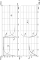
- figure 2 shows an example of the resistive power W' R , the elastic power W' C and the total power, i.e. the sum W' R + W' C , as a function of the actual ventilation frequency fact.
- the ventilation frequency fact in [rpm] is plotted on the x-axis, and the power in [ma/sec] on the y-axis.
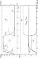
- figure 3 and figure 4 show an example of the time profile of the pressure P (above) and the time profile of the work done W (below) during a ventilation stroke.
- the time t in seconds is plotted on the x-axis, on the y-axis the pressure P in [mbar] and the volume flow Vol' in [I/sec] (top) and the work W in [Nm] (bottom).
- the time courses were determined using the two lung mechanical equations (14) and (15).
- C 30 ml/mbar.
- R 5 mbar/(l*sec)
- in figure 4 20 mbar/(l*sec).
- the setpoint pressure P set immediately increases to the maximum value during a ventilation stroke.
- figure 3 and figure 4 therefore show the response of the lung pneumatic system to a jump stimulus by the ventilator 1.
- the actual pressure P aw achieved by the sub-regulation cannot immediately rise to the full value.
- the risk must be excluded or at least reduced that the lung Lu of the patient P damaged by a too rapid increase in pressure.
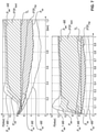
- the desired time profile P set of the pressure is therefore specified in such a way that it increases at the beginning of a ventilation stroke until it reaches the maximum value. This period of time between the beginning of the ventilation stroke and reaching the maximum value for the pressure P aw is referred to as the actual ramp time t R, actual.
- the desired progression over time P set of the pressure includes a pressure rise in a predefined setpoint ramp time t R,set and then a maximum setpoint pressure.
- a target ramp time t R,set By specifying a target ramp time t R,set , the resistive work W R is reduced compared to a sudden increase in the target pressure P set , while the elastic work W C remains unchanged.
- the maximum volume flows are reduced.
- figure 5 shows the chronological sequences, which are also shown in figure 3 and figure 4 are shown, where in the example of figure 5 a controlled increase in pressure is carried out.
- the lung compliance C 30 ml/mbar
- the lung resistance R 5 mbar/(l*sec)
- the ventilation frequency fact 15/min
- the ramp time t R, act 0.25 sec.
- a minute volume of V' A, actual 7.9 l/min is achieved.
- the elastic work Wc remains unchanged.
- Both the resistive power W' R and the elastic power W' C depend on the actual ventilation frequency f actual .
- the resistive power W' R is always greater than the elastic power W'c.
- the ideal mandatory setpoint frequency f set,mand,id is determined depending on the effect of the actual ventilation frequency f ist on the resistive power W' R and on the elastic power W' C.
- Relationship (17) shows how, under assumption (18), the sought-after ideal ventilation frequency f set,mand,id , the duration Ti of a ventilation stroke, and the temporal inhalation portion D1 are related.
- a specific actual ventilation frequency fact and a specific duration Ti of the ventilation strokes result in a specific resistive power W' R and a specific elastic power W' C .
- the ideal mandatory setpoint ventilation frequency f set,mand,id sought is calculated in such a way that a function that depends on the two powers W′ R and W′ C is minimized.
- This function is, for example, the sum of the two powers, ie W' R + Wc, or the quotient W' R / W' C from the two powers.
- the ideal mandatory setpoint respiration rate f set,mand,id is calculated in such a way that the elastic power W′ C is approximately equal to the resistive power W′ R .
- this specification leads to a comparatively low mechanical load on the lungs Lu of the patient P. More precisely: a factor a is specified, with a preferably being between 0 and 0.2 and particularly preferably equal to 0.1. 1+ ⁇ then acts as the power factor.
- the lung time constant T is measured on patient P.
- the signal processing unit 10 preferably evaluates measured values that have been supplied by the sensors 3 and 15, and uses the evaluation to determine the airway pressure P aw and the volume flow Vol′.
- the signal processing unit 10 derives an estimate for the product R*C from these signals P aw and Vol′ and uses this estimate as the lung time constant T of the patient P.
- an ideal jump in pressure P aw can be assumed when determining the lung time constant T , and the lung time constant T can then be derived solely from the measured volume flow Vol'.
- the procedure of determining the mandatory setpoint ventilation frequency f set,mand according to calculation rule (23) leads to a simple and robust specification of a setpoint value f set,mand for the ventilation frequency factual under mandatory ventilation.
- a lower setpoint ventilation frequency f set,mand is calculated than with other methods, so that the procedure according to the invention results in less stress on the artificially ventilated lung Lu, especially in a patient P with a relatively small lung time constant T.
- An advantage of the embodiment just described is that it is not necessary to measure lung resistance R and lung compliance C separately. This is associated with a relatively large degree of uncertainty, particularly when the patient P is breathing spontaneously. It is sufficient to measure the lung time constant T, i.e. the product R*C. A sufficiently reliable value for the lung time constant T is usually obtained after a few breaths, which the patient's own breathing muscles perform, or a few ventilation strokes of the ventilator 1 .
- the embodiment just described does not require optimization to be performed at run time.
- this function describes, for example, the work done during a ventilation stroke or the power that is applied during the ventilation strokes. If an optimization were required at runtime, a relatively high computing capacity and/or a relatively long computing time would be required.
- an optimization is often carried out using an iterative process, which is terminated when a termination criterion is met. In some cases, the value found can be relatively far from an optimum.
- the procedure just described also does not necessarily require a so-called maneuver to be carried out during the artificial ventilation, in which an operating parameter of the ventilator 1, for example a required time profile of the pressure or the volume flow, is specifically set to a different value for a short period of time to measure a vital parameter of the patient P.
- an operating parameter of the ventilator for example a required time profile of the pressure or the volume flow
- no occlusion is required, in which the artificial respiration is stopped for a short period of time and optionally also the patient P's own respiratory activity is prevented for this short period of time in order to measure the time-varying pressure caused by the patient P's own respiratory activity .
- Such a maneuver often puts a strain on patient P.
- the procedure according to the invention just described results in the mandatory ventilation being carried out with a ventilation frequency fact which is not higher than required in order to achieve the desired alveolar minute volume V′ A,req . For this reason, this procedure reduces the mechanical load on the lungs Lu of the patient P in many cases. For this reason, the procedure reduces the risk of the patient P's lungs Lu being mechanically damaged.
- the target alveolar minute volume V' A,req is specified for the ventilator 1 during artificial ventilation. Procedures for doing this are described, for example, in J Fernández, D Miguelena, H Mulett, J Godoy, and F Martinón-Torres, "Adaptive support ventilation: State of the art review," Indian J Crit. Care Med., vol. 17, no. 1, p. 16, 2013 , described.
- the total dead space volume V D is also determined at the beginning of the artificial respiration, preferably using one of the two methods described above.
- the patient-side dead space volume V D,Pat is preferably repeatedly measured during the entire artificial respiration, and a change in the patient-side dead space volume V D,Pat is thus detected and taken into account.
- the factors a and x are preferably predefined once and are stored in the ventilator 1 .
- a value for the factor a is specified. It is also possible to specify n values ⁇ 1 , . . . , ⁇ n for factor a. The calculation just described is performed for each given factor ⁇ 1 ,...,an. This yields n values f set,mand ( ⁇ 1 ), ..., f set,mand ( ⁇ n ). A value that is calculated from these n values by a suitable averaging or formation of the median or other aggregation is used as the mandatory setpoint ventilation frequency f set,mand . For example, the smallest of these n values is used.
- the procedure described above shows a way of setting a target ventilation frequency f set,mand for mandatory artificial ventilation of the Derive patient P automatically.
- a target alveolar minute volume V' A,req or a proximal minute volume is specified.
- This setpoint ventilation frequency f set,mand is then used for the subordinate control described above when the patient P is completely anesthetized and therefore does not perform any breathing activity of his own.
- a target alveolar minute volume V' A,req is specified for the method. If the patient P is completely anesthetized, this minute volume V' A,req is generated exclusively by the artificial ventilation (mandatory ventilation). This mandatory ventilation is carried out with the setpoint ventilation frequency f set,mand , which is defined as just described.
- This factor SML is also determined and used.
- a measure of the negative pressure P mus generated by the activity of the diaphragm Zw and the intercostal muscles of the patient P is measured. Then both the airway pressure P aw , which is applied to the lungs Lu from the outside, and the negative pressure P mus acting on the lungs Lu from the inside are known. From the two signals P aw and P mus that alveolar minute volume V' A,spon is derived which is achieved exclusively through the patient P's own respiratory activity. Because the signal P aw is caused by an overlay of one's own respiratory activity with the artificial respiration, the signal P mus exclusively by one's own respiratory activity.
- the esophageal pressure P es is measured.
- the probe 3 is inserted into the esophagus Sp of the patient P and a measure for the esophageal pressure P es measures.
- signals from the measuring electrodes 5.1.1 to 5.1.2 are used to approximately measure the electrical activity of the muscles of the patient P's respiratory system. This electrical activity causes the patient P's own respiratory activity and does not depend on artificial respiration.
- the fact is exploited that when the patient P's own respiratory activity is supported by the processing device 1, spontaneous or stimulated breaths of the patient P are detected and each detected sufficiently large spontaneous or stimulated breath triggers a ventilation stroke of the processing device 1 .
- the stronger his own respiratory activity the more ventilation strokes of the ventilator 1 the patient P triggers.
- the number of ventilation strokes per unit of time triggered by patient P's own respiratory activity is counted.
- This other embodiment does not necessarily require the alveolar minute volume V' A,spon to be determined.
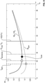
- figure 6 and figure 7 illustrate two embodiments of how the measure for the intensity of the patient P's own respiratory activity is determined.
- the patient P does not perform any breathing activity of his own, and the processing device 1 also does not perform a ventilation stroke, so that at the beginning of the time period the two pressures P aw and P es approximately match. Subsequently, these two pressures differ from each other, due to one's own respiratory activity and/or the artificial respiration that sets in later.
- FIG. 6 uses the work of breathing (WOB) expended to inhale during a breath.
- the pressure P in [mbar] is plotted on the x-axis, and the volume Vol in [I] flowing into the lungs Lu and out of the lungs Lu is plotted on the y-axis.
- the esophagus pressure P es which is measured using the probe 3, is used as a measure of the pressure generated by the diaphragm Zw of the patient P.
- the esophageal pressure P es is measured as a measure of the pressure P mus exerted by the diaphragm Zw, specifically with the aid of the probe 3 in the esophagus Sp of the patient P.
- the time profiles of the pressure P aw and the volume flow Vol' are measured at the mouth of the patient P, preferably using the sensor 2 and optionally the sensor 15, and a measure for the pressure P mus is derived from these time profiles using a lung model. Averaging over several inhalations is preferred.
- the total work done in one inspiration WOB is the sum of WOB Pat and WOB Vent .
- the SML factor in the example on the left is about 41%, in the example on the right it is only 13%.
- an average work is preferably calculated.
- the patient P's own respiratory activity is quantitatively recorded relatively well.
- PTP means "pressure-time product”.
- the time t in [sec] is plotted on the x-axis, and the pressure in [mbar] for the two pressures P aw and P es on the y-axis.
- the dividing line TL runs through the intersection of the curves of P aw and P es .
- the area PTP Pat between the time profile of the pressure P es and the dividing line TL is a measure of the mean pressure P mus that the patient P applies through his own breathing activity and correlates with the mechanical performance of the patient P's own breathing activity
- the area PTPvent between the time course of the pressure P aw and the dividing line TL is a measure of the mean pressure P aw applied by the ventilator 1 and correlates with the mechanical performance of the artificial respiration.
- the ventilator 1 is operated in such a way that a desired course over time of the airway pressure P aw or of the volume flow Vol′ is achieved during the artificial respiration.
- a target timing is set, and subordinate regulation or control is performed with the aim that the actual timing is equal to the target timing.
- the ventilator 1 executes a sequence of ventilation strokes. Some of these ventilation strokes are triggered by the patient P's own respiratory activity, the rest automatically by the ventilator 1 in order to achieve the desired time profile of the pressure or volume flow. With a sufficiently intense own Breathing activity, it is also possible for each ventilation stroke of the ventilator 1 to be triggered by a patient P breathing.
- n spon denotes the number of ventilation strokes that are triggered within a period of time by the patient P's own respiratory activity
- n tot denotes the total number of ventilation strokes of the ventilator 1 carried out in this period.
- an ideal frequency f spon of the patient P's own respiratory activity is calculated.
- This ideal frequency f spon requires the lowest power W' R + W' C in order to achieve the desired alveolar minute volume V' A,req through one's own breathing activity. In other words: Any other frequency of one's own breathing activity requires a higher performance.
- the entire dead space volume V D is taken into account in this calculation, ie in addition to the dead space volume V D,Pat on the patient side, the dead space volume V D,Ger on the device side is also taken into account.
- f spon is the ideal frequency of one's own breathing activity, which is calculated, for example, according to calculation rule (30)
- f set,mand is the target ventilation frequency for mandatory ventilation specified according to the invention
- SML is the factor, which is calculated, for example, according to calculation rule (29) or using the esophagus pressure P it is determined according to the calculation rule (26) or according to (27) or (28).
- the configuration according to specification (31) avoids an abrupt transition between supportive and mandatory ventilation when the patient P's own respiratory activity changes. Rather, a gradual transition is achieved, with the mandatory ventilation becoming weaker the stronger the patient P's own respiratory activity is, and vice versa.
- a deviation ensures that the target ventilation frequency f set is at least as great as the ideal frequency f spon of one's own breathing activity.
- An operating parameter that can be set on the ventilator 1 is the target tidal volume VOL Tid,set , ie the volume that is to be applied to the mouth of the patient P during a breathing cycle.
- This volume essentially corresponds to the volume that is to be ejected from the ventilator 1 during a ventilation stroke.
- a subordinate regulation or control receives the target tidal volume VOL Tid,set as a specification and controls the ventilator 1 with the aim that the tidal volume Vol Tid,actually achieved by the ventilation strokes is equal to the calculated target tidal volume VOL Tid,set .
- the actual achieved tidal volume Tid Vol,act is expelled into the fluid link during an inspiration event and is shared between the achieved alveolar lung volume V A, act and the dead space in tubing of the fluid link and in the upper and middle airways of the patient P, where the total Dead space has the volume V D .
- the actual tidal volume Tid Vol,act is intended to generate the required alveolar minute volume V' A,req and depends on the actual ventilation frequency fact and the dead space volume VD .
- volume tid , set V' A , req f set + V D
- the target tidal volume VOl Tid,set is calculated according to the calculation rule below.
- the ventilation frequency f minW is also entered, which leads to a minimum total power W' R +W' C.
- This ventilation frequency f minW can be calculated by minimizing.
- the method according to the invention avoids such a minimization.
- the ventilation rate is f minW for the minimum Power greater than the ideal mandatory target ventilation rate f set,mand,id .
- the calculated setpoint respiration frequency f set and the specified setpoint tidal volume VOL Tid,set are displayed on the display and control unit 12 .
- a user can confirm these values or overwrite a displayed value with a manually entered value.
- ⁇ b> ⁇ u>List of symbols ⁇ /u> ⁇ /b> 1 The ventilator that artificially ventilates the patient P includes the display and control unit 12 and the signal processing unit 10 2 pneumatic sensor unit in front of the patient P's mouth, measures the airway pressure P aw and optionally the volume flow Vol', acts as the airway pressure sensor, comprises the components 2.1 and 2.2 2.1 Measured value pickup of the sensor unit 2 picks up a gas sample from the fluid connection between the lungs Lu of the patient P and the ventilator 1 2.2 Actual pressure sensor of the sensor unit 2, evaluates the gas sample from the measuring sensor 2.1 3 Probe in the patient P's esophagus Sp, measures the esophagus pressure P es and optionally the gastric pressure P ga , connected to
Applications Claiming Priority (1)
| Application Number | Priority Date | Filing Date | Title |
|---|---|---|---|
| DE102020123138.5A DE102020123138B3 (de) | 2020-09-04 | 2020-09-04 | Verfahren und Vorrichtung zur automatischen Festlegung der Sollfrequenz eines Beatmungsgeräts |
Publications (2)
| Publication Number | Publication Date |
|---|---|
| EP3964253A1 true EP3964253A1 (fr) | 2022-03-09 |
| EP3964253B1 EP3964253B1 (fr) | 2023-06-28 |
Family
ID=77499703
Family Applications (1)
| Application Number | Title | Priority Date | Filing Date |
|---|---|---|---|
| EP21193003.7A Active EP3964253B1 (fr) | 2020-09-04 | 2021-08-25 | Programme d'ordinateur et dispositif de détermination automatique de la fréquence de consigne d'un respirateur |
Country Status (3)
| Country | Link |
|---|---|
| US (1) | US20220072249A1 (fr) |
| EP (1) | EP3964253B1 (fr) |
| DE (1) | DE102020123138B3 (fr) |
Families Citing this family (1)
| Publication number | Priority date | Publication date | Assignee | Title |
|---|---|---|---|---|
| DE102022101845A1 (de) | 2021-06-18 | 2022-12-22 | Drägerwerk AG & Co. KGaA | Beatmungsvorrichtung, Verfahren, Computerprogramm und Vorrichtung zum Ermitteln eines Maßes für einen intrinsischen endexspiratorischen Druck |
Citations (6)
| Publication number | Priority date | Publication date | Assignee | Title |
|---|---|---|---|---|
| WO2007131314A1 (fr) * | 2006-05-12 | 2007-11-22 | Yrt Limited | Procédé et dispositif pour générer un signal reflétant les efforts respiratoires de patients sous assistance respiratoire |
| US20080236582A1 (en) * | 2007-03-31 | 2008-10-02 | Tehrani Fleur T | Weaning and decision support system for mechanical ventilation |
| US20090007915A1 (en) | 2006-01-30 | 2009-01-08 | Hamilton Medical Ag | Apparatus for regulating a mechanical ventilation |
| EP2246087A1 (fr) * | 2009-04-30 | 2010-11-03 | General Electric Company | Systèmes et procédés de ventilation de patient |
| WO2013027137A1 (fr) * | 2011-08-25 | 2013-02-28 | Koninklijke Philips Electronics N.V. | Mesure non invasive de la ventilation |
| EP3332827A1 (fr) | 2016-12-06 | 2018-06-13 | Iasset Ag | Appareil de ventilateur et procédé de fonctionnement d'un ventilateur dans ledit appareil de ventilateur |
Family Cites Families (1)
| Publication number | Priority date | Publication date | Assignee | Title |
|---|---|---|---|---|
| WO2016178111A1 (fr) | 2015-05-05 | 2016-11-10 | Koninklijke Philips N.V. | Systèmes et procédés pour une segmentation améliorée de la toux |
-
2020
- 2020-09-04 DE DE102020123138.5A patent/DE102020123138B3/de active Active
-
2021
- 2021-08-25 EP EP21193003.7A patent/EP3964253B1/fr active Active
- 2021-09-03 US US17/466,787 patent/US20220072249A1/en active Pending
Patent Citations (6)
| Publication number | Priority date | Publication date | Assignee | Title |
|---|---|---|---|---|
| US20090007915A1 (en) | 2006-01-30 | 2009-01-08 | Hamilton Medical Ag | Apparatus for regulating a mechanical ventilation |
| WO2007131314A1 (fr) * | 2006-05-12 | 2007-11-22 | Yrt Limited | Procédé et dispositif pour générer un signal reflétant les efforts respiratoires de patients sous assistance respiratoire |
| US20080236582A1 (en) * | 2007-03-31 | 2008-10-02 | Tehrani Fleur T | Weaning and decision support system for mechanical ventilation |
| EP2246087A1 (fr) * | 2009-04-30 | 2010-11-03 | General Electric Company | Systèmes et procédés de ventilation de patient |
| WO2013027137A1 (fr) * | 2011-08-25 | 2013-02-28 | Koninklijke Philips Electronics N.V. | Mesure non invasive de la ventilation |
| EP3332827A1 (fr) | 2016-12-06 | 2018-06-13 | Iasset Ag | Appareil de ventilateur et procédé de fonctionnement d'un ventilateur dans ledit appareil de ventilateur |
Non-Patent Citations (3)
| Title |
|---|
| J. FERNANDEZD. MIGUELENAH. MULETTJ. GODOYF. MARTINÖN-TORRES: "Adaptive support Ventilation: State of the art review", INDIAN J. CRIT. CARE MED., vol. 17, no. 1, 2013, pages 16 |
| J. MEAD: "Control of respiratory frequency", J. APPL. PHYSIOL., vol. 15, no. 3, 1960, pages 325 - 336 |
| REES S E ET AL: "Using physiological models and decision theory for selecting appropriate ventilator settings", JOURNAL OF CLINICAL MONITORING AND COMPUTING, SPRINGER NETHERLANDS, NL, vol. 20, no. 6, 15 September 2006 (2006-09-15), XP037122867, ISSN: 1387-1307, [retrieved on 20060915], DOI: 10.1007/S10877-006-9049-5 * |
Also Published As
| Publication number | Publication date |
|---|---|
| DE102020123138B3 (de) | 2021-11-04 |
| CN114129840A (zh) | 2022-03-04 |
| EP3964253B1 (fr) | 2023-06-28 |
| US20220072249A1 (en) | 2022-03-10 |
Similar Documents
| Publication | Publication Date | Title |
|---|---|---|
| EP2934640B1 (fr) | Système de ventilation | |
| DE60126694T2 (de) | Beatmungsgerät | |
| DE102007062214C5 (de) | Verfahren zum automatischen Steuern eines Beatmungssystems sowie zugehörige Beatmungsvorrichtung | |
| DE69922511T2 (de) | Respiratorisches unterstützungssystem mit detektion der atmung unter aufnahme neuroelektrischer signale | |
| DE102008008823A1 (de) | Einstellung mechanischer Zwangsbeatmungsparameter basierend auf der Patientenphysiologie | |
| EP1148907B1 (fr) | Procede non invasif pour l'optimisation de la respiration de poumons atelectasiques | |
| DE69735428T2 (de) | Gerät zur beatmung während der anästhesie | |
| EP2892427B1 (fr) | Système d'ajustement automatique d'une pression prescrite par un dispositif respiratoire | |
| DE112004001957T5 (de) | System und Verfahren zur Zwerchfellstimulation | |
| EP3653248B1 (fr) | Appareils respiratoires | |
| DE102008014479A1 (de) | Einstellen der Ausatmungszeit bei der mandatorischen mechanischen Ventilation auf der Grundlage einer Abweichung von einem stabilen Zustand von endtidalen Gaskonzentrationen | |
| EP3725222B1 (fr) | Système et appareil respiratoire de détermination en temps réel d'une contrainte locale d'un poumon pendant la respiration artificielle | |
| DE102006018198A1 (de) | Verfahren und Vorrichtung zur Lungenventilation | |
| EP2265179B1 (fr) | Dispositif et méthode d'évaluation du stress circulatoire d'une personne pendant une assistance respiratoire | |
| EP3964253B1 (fr) | Programme d'ordinateur et dispositif de détermination automatique de la fréquence de consigne d'un respirateur | |
| DE102018003026A1 (de) | Beatmungsvorrichtung mit einem Sicherheitsventil | |
| DE102021000313A1 (de) | Verfahren zum Betreiben eines Beatmungsgeräts zur künstlichen Beatmung eines Patienten sowie ein solches Beatmungsgerät | |
| DE102018003027A1 (de) | Beatmungsvorrichtung | |
| EP3957241B1 (fr) | Agencement et produit programme d'ordinateur de détermination de la compliance pulmonaire par zones | |
| DE102015011390A1 (de) | Vorrichtung, Verfahren und Computerprogramm zur Beatmung eines Patienten | |
| DE102022101845A1 (de) | Beatmungsvorrichtung, Verfahren, Computerprogramm und Vorrichtung zum Ermitteln eines Maßes für einen intrinsischen endexspiratorischen Druck | |
| LU102031B1 (de) | Verfahren und Vorrichtung zur automatischen Festlegung der Sollfrequenz eines Beatmungsgeräts | |
| EP1985326B9 (fr) | Appareil respiratoire avec une détermination de la ventilation alvéolaire | |
| WO2021089215A1 (fr) | Procédé et unité de traitement de signaux pour déterminer l'activité respiratoire d'un patient | |
| DE102020001440A1 (de) | Beatmungsvorrichtung |
Legal Events
| Date | Code | Title | Description |
|---|---|---|---|
| PUAI | Public reference made under article 153(3) epc to a published international application that has entered the european phase |
Free format text: ORIGINAL CODE: 0009012 |
|
| STAA | Information on the status of an ep patent application or granted ep patent |
Free format text: STATUS: REQUEST FOR EXAMINATION WAS MADE |
|
| 17P | Request for examination filed |
Effective date: 20220131 |
|
| AK | Designated contracting states |
Kind code of ref document: A1 Designated state(s): AL AT BE BG CH CY CZ DE DK EE ES FI FR GB GR HR HU IE IS IT LI LT LU LV MC MK MT NL NO PL PT RO RS SE SI SK SM TR |
|
| STAA | Information on the status of an ep patent application or granted ep patent |
Free format text: STATUS: EXAMINATION IS IN PROGRESS |
|
| 17Q | First examination report despatched |
Effective date: 20220504 |
|
| GRAP | Despatch of communication of intention to grant a patent |
Free format text: ORIGINAL CODE: EPIDOSNIGR1 |
|
| STAA | Information on the status of an ep patent application or granted ep patent |
Free format text: STATUS: GRANT OF PATENT IS INTENDED |
|
| GRAJ | Information related to disapproval of communication of intention to grant by the applicant or resumption of examination proceedings by the epo deleted |
Free format text: ORIGINAL CODE: EPIDOSDIGR1 |
|
| STAA | Information on the status of an ep patent application or granted ep patent |
Free format text: STATUS: EXAMINATION IS IN PROGRESS |
|
| INTG | Intention to grant announced |
Effective date: 20221220 |
|
| INTC | Intention to grant announced (deleted) | ||
| GRAP | Despatch of communication of intention to grant a patent |
Free format text: ORIGINAL CODE: EPIDOSNIGR1 |
|
| STAA | Information on the status of an ep patent application or granted ep patent |
Free format text: STATUS: GRANT OF PATENT IS INTENDED |
|
| GRAS | Grant fee paid |
Free format text: ORIGINAL CODE: EPIDOSNIGR3 |
|
| INTG | Intention to grant announced |
Effective date: 20230221 |
|
| GRAA | (expected) grant |
Free format text: ORIGINAL CODE: 0009210 |
|
| STAA | Information on the status of an ep patent application or granted ep patent |
Free format text: STATUS: THE PATENT HAS BEEN GRANTED |
|
| AK | Designated contracting states |
Kind code of ref document: B1 Designated state(s): AL AT BE BG CH CY CZ DE DK EE ES FI FR GB GR HR HU IE IS IT LI LT LU LV MC MK MT NL NO PL PT RO RS SE SI SK SM TR |
|
| REG | Reference to a national code |
Ref country code: CH Ref legal event code: EP |
|
| REG | Reference to a national code |
Ref country code: AT Ref legal event code: REF Ref document number: 1582163 Country of ref document: AT Kind code of ref document: T Effective date: 20230715 |
|
| REG | Reference to a national code |
Ref country code: IE Ref legal event code: FG4D Free format text: LANGUAGE OF EP DOCUMENT: GERMAN |
|
| REG | Reference to a national code |
Ref country code: DE Ref legal event code: R096 Ref document number: 502021000924 Country of ref document: DE |
|
| REG | Reference to a national code |
Ref country code: LT Ref legal event code: MG9D |
|
| PG25 | Lapsed in a contracting state [announced via postgrant information from national office to epo] |
Ref country code: SE Free format text: LAPSE BECAUSE OF FAILURE TO SUBMIT A TRANSLATION OF THE DESCRIPTION OR TO PAY THE FEE WITHIN THE PRESCRIBED TIME-LIMIT Effective date: 20230628 Ref country code: NO Free format text: LAPSE BECAUSE OF FAILURE TO SUBMIT A TRANSLATION OF THE DESCRIPTION OR TO PAY THE FEE WITHIN THE PRESCRIBED TIME-LIMIT Effective date: 20230928 |
|
| REG | Reference to a national code |
Ref country code: NL Ref legal event code: MP Effective date: 20230628 |
|
| PG25 | Lapsed in a contracting state [announced via postgrant information from national office to epo] |
Ref country code: RS Free format text: LAPSE BECAUSE OF FAILURE TO SUBMIT A TRANSLATION OF THE DESCRIPTION OR TO PAY THE FEE WITHIN THE PRESCRIBED TIME-LIMIT Effective date: 20230628 Ref country code: NL Free format text: LAPSE BECAUSE OF FAILURE TO SUBMIT A TRANSLATION OF THE DESCRIPTION OR TO PAY THE FEE WITHIN THE PRESCRIBED TIME-LIMIT Effective date: 20230628 Ref country code: LV Free format text: LAPSE BECAUSE OF FAILURE TO SUBMIT A TRANSLATION OF THE DESCRIPTION OR TO PAY THE FEE WITHIN THE PRESCRIBED TIME-LIMIT Effective date: 20230628 Ref country code: LT Free format text: LAPSE BECAUSE OF FAILURE TO SUBMIT A TRANSLATION OF THE DESCRIPTION OR TO PAY THE FEE WITHIN THE PRESCRIBED TIME-LIMIT Effective date: 20230628 Ref country code: HR Free format text: LAPSE BECAUSE OF FAILURE TO SUBMIT A TRANSLATION OF THE DESCRIPTION OR TO PAY THE FEE WITHIN THE PRESCRIBED TIME-LIMIT Effective date: 20230628 Ref country code: GR Free format text: LAPSE BECAUSE OF FAILURE TO SUBMIT A TRANSLATION OF THE DESCRIPTION OR TO PAY THE FEE WITHIN THE PRESCRIBED TIME-LIMIT Effective date: 20230929 |
|
| PGFP | Annual fee paid to national office [announced via postgrant information from national office to epo] |
Ref country code: FR Payment date: 20230821 Year of fee payment: 3 Ref country code: DE Payment date: 20230822 Year of fee payment: 3 |
|
| PG25 | Lapsed in a contracting state [announced via postgrant information from national office to epo] |
Ref country code: FI Free format text: LAPSE BECAUSE OF FAILURE TO SUBMIT A TRANSLATION OF THE DESCRIPTION OR TO PAY THE FEE WITHIN THE PRESCRIBED TIME-LIMIT Effective date: 20230628 |
|
| PG25 | Lapsed in a contracting state [announced via postgrant information from national office to epo] |
Ref country code: SK Free format text: LAPSE BECAUSE OF FAILURE TO SUBMIT A TRANSLATION OF THE DESCRIPTION OR TO PAY THE FEE WITHIN THE PRESCRIBED TIME-LIMIT Effective date: 20230628 |
|
| PG25 | Lapsed in a contracting state [announced via postgrant information from national office to epo] |
Ref country code: ES Free format text: LAPSE BECAUSE OF FAILURE TO SUBMIT A TRANSLATION OF THE DESCRIPTION OR TO PAY THE FEE WITHIN THE PRESCRIBED TIME-LIMIT Effective date: 20230628 |
|
| PG25 | Lapsed in a contracting state [announced via postgrant information from national office to epo] |
Ref country code: IS Free format text: LAPSE BECAUSE OF FAILURE TO SUBMIT A TRANSLATION OF THE DESCRIPTION OR TO PAY THE FEE WITHIN THE PRESCRIBED TIME-LIMIT Effective date: 20231028 |
|
| PG25 | Lapsed in a contracting state [announced via postgrant information from national office to epo] |
Ref country code: SM Free format text: LAPSE BECAUSE OF FAILURE TO SUBMIT A TRANSLATION OF THE DESCRIPTION OR TO PAY THE FEE WITHIN THE PRESCRIBED TIME-LIMIT Effective date: 20230628 Ref country code: SK Free format text: LAPSE BECAUSE OF FAILURE TO SUBMIT A TRANSLATION OF THE DESCRIPTION OR TO PAY THE FEE WITHIN THE PRESCRIBED TIME-LIMIT Effective date: 20230628 Ref country code: RO Free format text: LAPSE BECAUSE OF FAILURE TO SUBMIT A TRANSLATION OF THE DESCRIPTION OR TO PAY THE FEE WITHIN THE PRESCRIBED TIME-LIMIT Effective date: 20230628 Ref country code: PT Free format text: LAPSE BECAUSE OF FAILURE TO SUBMIT A TRANSLATION OF THE DESCRIPTION OR TO PAY THE FEE WITHIN THE PRESCRIBED TIME-LIMIT Effective date: 20231030 Ref country code: IS Free format text: LAPSE BECAUSE OF FAILURE TO SUBMIT A TRANSLATION OF THE DESCRIPTION OR TO PAY THE FEE WITHIN THE PRESCRIBED TIME-LIMIT Effective date: 20231028 Ref country code: ES Free format text: LAPSE BECAUSE OF FAILURE TO SUBMIT A TRANSLATION OF THE DESCRIPTION OR TO PAY THE FEE WITHIN THE PRESCRIBED TIME-LIMIT Effective date: 20230628 Ref country code: EE Free format text: LAPSE BECAUSE OF FAILURE TO SUBMIT A TRANSLATION OF THE DESCRIPTION OR TO PAY THE FEE WITHIN THE PRESCRIBED TIME-LIMIT Effective date: 20230628 Ref country code: CZ Free format text: LAPSE BECAUSE OF FAILURE TO SUBMIT A TRANSLATION OF THE DESCRIPTION OR TO PAY THE FEE WITHIN THE PRESCRIBED TIME-LIMIT Effective date: 20230628 |
|
| PG25 | Lapsed in a contracting state [announced via postgrant information from national office to epo] |
Ref country code: PL Free format text: LAPSE BECAUSE OF FAILURE TO SUBMIT A TRANSLATION OF THE DESCRIPTION OR TO PAY THE FEE WITHIN THE PRESCRIBED TIME-LIMIT Effective date: 20230628 |
|
| PG25 | Lapsed in a contracting state [announced via postgrant information from national office to epo] |
Ref country code: MC Free format text: LAPSE BECAUSE OF FAILURE TO SUBMIT A TRANSLATION OF THE DESCRIPTION OR TO PAY THE FEE WITHIN THE PRESCRIBED TIME-LIMIT Effective date: 20230628 |
|
| PG25 | Lapsed in a contracting state [announced via postgrant information from national office to epo] |
Ref country code: MC Free format text: LAPSE BECAUSE OF FAILURE TO SUBMIT A TRANSLATION OF THE DESCRIPTION OR TO PAY THE FEE WITHIN THE PRESCRIBED TIME-LIMIT Effective date: 20230628 |
|
| PG25 | Lapsed in a contracting state [announced via postgrant information from national office to epo] |
Ref country code: LU Free format text: LAPSE BECAUSE OF NON-PAYMENT OF DUE FEES Effective date: 20230825 |
|
| PG25 | Lapsed in a contracting state [announced via postgrant information from national office to epo] |
Ref country code: LU Free format text: LAPSE BECAUSE OF NON-PAYMENT OF DUE FEES Effective date: 20230825 Ref country code: DK Free format text: LAPSE BECAUSE OF FAILURE TO SUBMIT A TRANSLATION OF THE DESCRIPTION OR TO PAY THE FEE WITHIN THE PRESCRIBED TIME-LIMIT Effective date: 20230628 |
|
| PLBE | No opposition filed within time limit |
Free format text: ORIGINAL CODE: 0009261 |
|
| STAA | Information on the status of an ep patent application or granted ep patent |
Free format text: STATUS: NO OPPOSITION FILED WITHIN TIME LIMIT |