EP3964073A1 - Slitting apparatus - Google Patents
Slitting apparatus Download PDFInfo
- Publication number
- EP3964073A1 EP3964073A1 EP21803640.8A EP21803640A EP3964073A1 EP 3964073 A1 EP3964073 A1 EP 3964073A1 EP 21803640 A EP21803640 A EP 21803640A EP 3964073 A1 EP3964073 A1 EP 3964073A1
- Authority
- EP
- European Patent Office
- Prior art keywords
- slit forming
- clamper
- station
- angle
- forming device
- Prior art date
- Legal status (The legal status is an assumption and is not a legal conclusion. Google has not performed a legal analysis and makes no representation as to the accuracy of the status listed.)
- Granted
Links
Images



Classifications
-
- A—HUMAN NECESSITIES
- A22—BUTCHERING; MEAT TREATMENT; PROCESSING POULTRY OR FISH
- A22C—PROCESSING MEAT, POULTRY, OR FISH
- A22C21/00—Processing poultry
- A22C21/0023—Dividing poultry
-
- A—HUMAN NECESSITIES
- A22—BUTCHERING; MEAT TREATMENT; PROCESSING POULTRY OR FISH
- A22C—PROCESSING MEAT, POULTRY, OR FISH
- A22C21/00—Processing poultry
- A22C21/0069—Deboning poultry or parts of poultry
- A22C21/0076—Deboning poultry legs and drumsticks
-
- A—HUMAN NECESSITIES
- A22—BUTCHERING; MEAT TREATMENT; PROCESSING POULTRY OR FISH
- A22C—PROCESSING MEAT, POULTRY, OR FISH
- A22C17/00—Other devices for processing meat or bones
- A22C17/0006—Cutting or shaping meat
-
- A—HUMAN NECESSITIES
- A22—BUTCHERING; MEAT TREATMENT; PROCESSING POULTRY OR FISH
- A22B—SLAUGHTERING
- A22B5/00—Accessories for use during or after slaughtering
- A22B5/0017—Apparatus for cutting, dividing or deboning carcasses
-
- A—HUMAN NECESSITIES
- A22—BUTCHERING; MEAT TREATMENT; PROCESSING POULTRY OR FISH
- A22B—SLAUGHTERING
- A22B7/00—Slaughterhouse arrangements
- A22B7/001—Conveying arrangements
- A22B7/004—Rails for conveying suspended carcasses, e.g. configurations, connections
-
- A—HUMAN NECESSITIES
- A22—BUTCHERING; MEAT TREATMENT; PROCESSING POULTRY OR FISH
- A22C—PROCESSING MEAT, POULTRY, OR FISH
- A22C17/00—Other devices for processing meat or bones
- A22C17/004—Devices for deboning meat
-
- A—HUMAN NECESSITIES
- A22—BUTCHERING; MEAT TREATMENT; PROCESSING POULTRY OR FISH
- A22C—PROCESSING MEAT, POULTRY, OR FISH
- A22C17/00—Other devices for processing meat or bones
- A22C17/0093—Handling, transporting or packaging pieces of meat
-
- A—HUMAN NECESSITIES
- A22—BUTCHERING; MEAT TREATMENT; PROCESSING POULTRY OR FISH
- A22C—PROCESSING MEAT, POULTRY, OR FISH
- A22C21/00—Processing poultry
- A22C21/0046—Support devices
-
- A—HUMAN NECESSITIES
- A22—BUTCHERING; MEAT TREATMENT; PROCESSING POULTRY OR FISH
- A22C—PROCESSING MEAT, POULTRY, OR FISH
- A22C21/00—Processing poultry
- A22C21/0053—Transferring or conveying devices for poultry
-
- B—PERFORMING OPERATIONS; TRANSPORTING
- B65—CONVEYING; PACKING; STORING; HANDLING THIN OR FILAMENTARY MATERIAL
- B65G—TRANSPORT OR STORAGE DEVICES, e.g. CONVEYORS FOR LOADING OR TIPPING, SHOP CONVEYOR SYSTEMS OR PNEUMATIC TUBE CONVEYORS
- B65G47/00—Article or material-handling devices associated with conveyors; Methods employing such devices
- B65G47/74—Feeding, transfer, or discharging devices of particular kinds or types
- B65G47/84—Star-shaped wheels or devices having endless travelling belts or chains, the wheels or devices being equipped with article-engaging elements
- B65G47/841—Devices having endless travelling belts or chains equipped with article-engaging elements
- B65G47/842—Devices having endless travelling belts or chains equipped with article-engaging elements the article-engaging elements being grippers
Definitions
- the present disclosure relates to a slit forming device.
- Patent Document 1 proposes an automatic de-boning technique for bone-in meat
- Patent Document 2 proposes an automatic measurement technique of measuring the entire length of bone-in meat during conveyance
- Patent Document 3 proposes an automatic slit forming technique of forming a slit in bone-in meat during conveyance
- Patent Document 4 proposes an automatic de-boning technique increased in processing efficiency.
- an automatic slaughter technique for meat is required of, for example, improvement in processing efficiency (such as an increase in number of processes per unit time), a downsized automation device, versatility, and further improvement in yield of meat portions.
- the present disclosure was made in view of the above, and an object of the present disclosure is to downsize a device for automating slit formation and to increase efficiency.
- a slit forming device includes a clamper configured to pass through a plurality of stations arranged on a circumference, a slit forming blade disposed on an outer circumference side or an inner circumference side of a slit forming station among the plurality of stations, and a clamper rotating part capable of rotating the clamper about a vertical line such that a slit forming surface of a work faces the slit forming blade in the slit forming station.
- work refers to bone-in meat obtained by slaughtering a livestock carcass for meat or bone-in meat (for example, bone-in limb meat such as arm meat or thigh meat) in the middle of slaughtering.
- meat or bone-in meat for example, bone-in limb meat such as arm meat or thigh meat
- a slit forming device According to a slit forming device according to the present disclosure, it is possible to downsize a device for automating a slit forming step and to improve processing efficiency.
- an expression of relative or absolute arrangement such as “in a direction”, “along a direction”, “parallel”, “orthogonal”, “centered”, “concentric” and “coaxial” shall not be construed as indicating only the arrangement in a strict literal sense, but also includes a state where the arrangement is relatively displaced by a tolerance, or by an angle or a distance whereby it is possible to achieve the same function.
- an expression of an equal state such as “same”, “equal”, and “uniform” shall not be construed as indicating only the state in which the feature is strictly equal, but also includes a state in which there is a tolerance or a difference that can still achieve the same function.
- an expression of a shape such as a rectangular shape or a tubular shape shall not be construed as only the geometrically strict shape, but also includes a shape with unevenness or chamfered corners within the range in which the same effect can be achieved.
- FIGs. 1 to 3 each show a slit forming device 10 (10A) according to an embodiment.
- FIG. 1 is a side view of the slit forming device 10 (10A)
- FIG. 2 is a front view taken along line A-A in FIG. 1
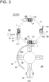
- FIG. 3 is a schematic plan view of the slit forming device 10 (10A).
- the slit forming device 10 (10A) includes a plurality of processing stations 1st to 4st arranged on a circumference C.
- a clamper 12 has a movement trajectory moving on the circumference C, and can pass through the plurality of stations while suspending a work W.
- the slit forming station 3st includes a slit forming blade 14 disposed on the outer side or inner side of the circumference C, and a clamper rotating part 16 (16a, 16b) capable of rotating the clamper 12 about a vertical line P.
- the clamper rotating part 16 is configured to be able to rotate the clamper 12 about the vertical line such that a slit forming surface S of the work W faces the slit forming blade 14 in the slit forming station 3st.
- the slit forming device 10 (10A) includes the loading station 2st upstream of the slit forming station 3st, and includes the discharge station 4st downstream of the slit forming station 3st.
- the clamper rotating part 16 includes the clamper rotating part 16 (16a) disposed in the loading station 2st, and the clamper rotating part 16 (16b) disposed in the discharge station 4st.
- the clamper 12 has an opening 12a where the work W is to be loaded, and the orientation of the opening 12a is set such that the slit forming surface S faces the slit forming blade 14 in the slit forming station 3st, by rotating the clamper 12 about the vertical line P with the clamper rotating part 16 (16a).
- the orientation of the slit forming surface S of the work W suspended by the clamper 12 and the orientation of the opening 12a of the clamper 12 are uniquely associated with each other, and once the angle of the opening 12a with respect to a tangent t to the circumference C is decided, the angle of the slit forming surface S with respect to the tangent t is uniquely decided.
- the plurality of stations 1st to 4st are arranged along the circumference C, it is possible to achieve downsized layout of the slit forming device 10 (10A). Further, with the clamper rotating part 16, with respect to the slit forming blade 14 placed in a position radially deviated from the circumferential movement trajectory of the clamper 12, it is possible to rotate the clamper 12 such that the slit forming surface S of the work W faces the slit forming blade 14. Thus, it is possible to reliably perform slit formation on the slit forming surface S, making it possible to improve processing efficiency (such as an increase in processing numbers per unit time).
- the slit forming device 10 (10A) includes the transfer station 1 st for loading the work W to the loading station 2st.
- the transfer station 1st loads the work W transferred by a work conveyance device (not shown) to the stopped clamper 12 in the loading station 2st.
- the transfer station 1st includes a reception part 20 for receiving the work W from the above-described work conveyance device, and a transfer part 22 for loading the work W received by the reception part 20 to the stopped clamper 12 in the loading station 2st.
- the reception part 20 has a slot 20a formed in the axial direction and pushes out, by a pusher (not shown) or the like, the work W suspended in the slot 20a to the transfer part 22.
- the transfer part 22 includes a rotational shaft 24 disposed in the vertical direction, a plurality of hangers 26 disposed around the rotational shaft 24, and a motor 28 for rotating the rotational shaft 24.
- a recess 26a where the work W is to be inserted and suspended is formed in the axial direction.
- the hanger 26 having received the work W from the reception part 20 is reversed by 180° to face the clamper 12 waiting in the loading station 2st, and transfers the work W to the clamper 12.
- a semi-circular guard ring 30 is provided in order to prevent the work W from falling off the recess 26a during the rotation of the hanger 26.
- a circular feed ring 32 is disposed in the horizontal direction.
- the feed ring 32 is configured to be rotatable about a vertical center axis by a drive device (not shown).
- a plurality of support shafts 33 are vertically disposed in the circumferential direction of the feed ring 32.
- Each support shaft 33 is supported to be lifted/lowered via a bracket 36 with respect to a pair of guide bars 34 mounted on the feed ring 32.
- the clamper 12 is disposed at a lower end of each support shaft 33, and is sent with tact feed so as to be paused in each station by the above-described drive device.
- the loading station 2st, the slit forming station 3st, and the discharge station 4st are disposed at intervals of 90°, and an interval between the discharge station 4st and the loading station 2st is at 180°. Then, the work W is loaded to the clamper 12 in the loading station 2st, the slit forming step is performed in the slit forming station 3st, and the work W having undergone slit formation is discharged in the discharge station 4st.
- the clamper rotating part 16 (16a, 16b) includes an air cylinder 40 mounted on a fixed support part (not shown), and a cam member 44 is mounted on a tip portion of a piston 42 of the air cylinder 40.
- the support shaft 33 has a double shaft structure inside of which a rotatable shaft 46 rotatable about the shaft is concentrically disposed, and the clamper 12 is mounted at a lower end of the rotatable shaft 46 and is configured to be rotatable about the shaft together with the rotatable shaft 46.
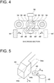
- FIG. 4 is a cross-sectional view taken along line B-B in FIG. 2 .
- a swing roller 48 is disposed integrally with the rotatable shaft 46 via an arm 49, and the swing roller 48 is rotatable about the rotatable shaft 46.
- a clasp 50 is disposed integrally with the support shaft 33, as well as a coil spring 52 is wound around the rotatable shaft 46, and one end of the coil spring 52 is connected to the clasp 50.
- the cam member 44 is mounted on the tip portion of the piston 42 to be rotatable about a shaft 42a, and is mounted to be rotatable about a shaft 54a which is disposed on a support plate 54 mounted on the fixed support part (not shown).
- the cam member 44 rotates about the shaft 54a, moves downward, and hits against the swing roller 48, causing the swing roller 48 to rotate about the rotatable shaft 46.
- the rotatable shaft 46 rotates about the shaft together with the swing roller 48. Consequently, the clamper 12 also rotates about the vertical line P together with the rotatable shaft 46. If the piston 42 retreats, and the cam member 44 retreats upward, the swing roller 48 returns to a position before rotation by a spring force of the coil spring 52.
- the slit forming device 10 includes a lifting/lowering means for lifting/lowering the clamper 12 at a predetermined height at a predetermined position.
- the bracket 36 includes a lifting/lowering roller 56 or 58 protruding to a radially inner side or outer side of the circumference C.
- equipment such as a drive device (not shown) for the feed ring 32 is disposed, and an outer plate (not shown) is provided to enclose the equipment.
- a traveling path (not shown) for allowing the lifting/lowering roller 56 or 58 to travel is formed.
- the lifting/lowering roller 56 or 58 travels through the above-described traveling path, lifting/lowering the rotatable shaft 46 and the clamper 12 (see Patent Document 1).
- the slit forming device 10 includes a chuck 60 rotatably disposed on the clamper 12, for opening/closing the opening 12a of the clamper 12, and a bar 62 disposed integrally with the chuck 60.
- a contact piece (not shown) contacting the bar 62 to rotate the chuck 60 is disposed.
- the contact piece contacts the bar 62 when the clamper 12 moves on the circumference C, operating the chuck 60 to open/close the opening 12a.
- the opening 12a is opened in the loading station 2st and the discharge station 4st to allow for loading and discharge of the work W, and the opening 12a is closed in the slit forming station 3st to prevent the work W from falling off.
- a control device for controlling a drive device for the chuck 60 is provided, and the control device may control an opening/closing timing of the chuck 60.
- the clamper 12 in the loading station 2st, when the work W is loaded from the transfer station 1st to the clamper 12, the clamper 12 is rotated by the clamper rotating part 16 (16a) in a direction of 12' indicated by a double-dotted chain line, and the opening 12a faces outward relative to the circumference C.
- the clamper rotating part 16 controls a rotation angle of the clamper 12 such that a difference between a first angle ⁇ 1, which is formed by the slit forming surface S with respect to the direction of the tangent t to the circumference C in the loading station 2st, and a second angle ⁇ 2, which is formed by the slit forming surface S with respect to the direction of the tangent t to the circumference C in the slit forming station 3st, falls within 80° to 100°.
- the first angle ⁇ 1 may change in accordance with the operation of the clamper rotating part 16 in the loading station 2st.
- the second angle ⁇ 2 may change in accordance with the operation of the clamper rotating part 16 in the slit forming station 3st.
- a value obtained by subtracting the second angle ⁇ 2 from the first angle ⁇ 1 falls within 80° to 100°.
- the present embodiment in the loading station 2st and the slit forming station 3st, it is possible to orient the slit forming surface S of the work W at the angle suitable for the processing operation in each of these stations, making it possible to improve working efficiency.
- the slit forming device 10 (10A) operates the clamper rotating part 16 (16a) to rotate the swing roller 48 by the cam member 44, thereby setting the slit forming surface S at the first angle ⁇ 1.
- the slit forming device 10 (10A) sets the slit forming surface S at the second angle ⁇ 2 by an elastic force of the coil spring 52 applied to the swing roller 48, without operating the clamper rotating part 16 (16a).
- the work W refers to bone-in meat (such as arm meat or thigh meat) obtained by slaughtering or in the middle of slaughtering a livestock carcass for meat. Then, an ankle portion is inserted into the slot 20a of the clamper 12 to be suspended.
- the work W is chicken thigh.
- the bone-in limb meat has one surface which is a first surface (meat surface) where meat is exposed, and another surface which is a second surface (skin surface) covered with skin. If the skin on the skin surface is cut in the slit forming step, a commercial value of boneless meat is decreased.
- the meat surface faces the slit forming blade 14 to be cut by the slit forming blade 14.
- the clamper rotating part 16 (16a) If the work W is the bone-in limb meat, the first surface and the second surface of the bone-in limb meat suspended by the clamper 12, and the opening 12a face the same direction.
- the first angle ⁇ 1 of the slit forming surface S in the loading station 2st is in a 90° direction orthogonal to the direction of the tangent t to the circumference C
- the second angle ⁇ 2 of the slit forming surface S in the slit forming station 3st is in a direction along the direction of the tangent t to the circumference C, that is 0°.
- the first angle ⁇ 1 is 90° in the loading station 2st, the work W is easily loaded to the clamper 12.
- the second angle ⁇ 2 is 0° in the slit forming station 3st, it is possible to arrange the work W such that the slit forming surface S of the work W faces the slit forming blade 14 placed in the position radially deviated from the circumferential trajectory of the clamper 12. Accordingly, it is possible to perform slit formation accurately and efficiently.
- the slit forming device 10 (10A) rotates the swing roller 48 by the cam member 44, thereby setting the first angle ⁇ 1 at 90°. Then, in the slit forming station 3st, the slit forming device 10 (10A) sets the second angle ⁇ 2 formed by the slit forming surface S always at 0° by keeping the rotatable shaft 46 applied with the elastic force of the coil spring 52, without rotating the swing roller 48 by the cam member 44.
- the slit forming device 10 (10A) includes the discharge station 4st downstream of the slit forming station 3st and performs an operation of discharging the work W having undergone slit formation in the discharge station 4st.
- the clamper rotating part 16 (16b) controls the slit forming surface S to have a third angle ⁇ 3 in the discharge station 4st, and rotates the clamper 12 such that a difference between the second angle ⁇ 2 and the third angle ⁇ 3 formed by the slit forming surface S in the discharge station 4st falls within 80° to 100°.
- the discharge station 4st it is possible to orient the work W at the angle suitable for the discharge operation, facilitating the discharge operation. Therefore, it is possible to improve processing efficiency of the slit forming device 10 (10A).
- the third angle ⁇ 3 may change in accordance with the operation of the clamper rotating part 16 in the discharge station 4st. In this case, it is only necessary that the difference between the second angle ⁇ 2 and the third angle ⁇ 3 while the work W is discharged in the discharge station 4st falls within 80° to 100°. For example, it is only necessary that a value obtained by subtracting the second angle ⁇ 2 from the third angle ⁇ 3 falls within 80° to 100°.
- the third angle ⁇ 3 may be the same as the first angle ⁇ 1.
- the clamper rotating part 16 can be operated easily.
- the slit forming device 10 (10A) sets the slit forming surface S at the second angle ⁇ 2 by the elastic force of the coil spring 52 applied to the swing roller 48, without operating the clamper rotating part 16 (16a).
- the slit forming device 10 (10A) operates the clamper rotating part 16 (16a) to rotate the swing roller 48 by the cam member 44, thereby setting the slit forming surface S at the third angle ⁇ 3.
- the third angle ⁇ 3 is in a direction orthogonal to a tangent direction to the circumference C.
- the opening 12a of the clamper 12 faces outward relative to the circumference C, facilitating discharge of the work W having undergone slit formation.
- the slit forming device 10 (10A) operates the clamper rotating part 16 (16b), lowers the cam member 44, and rotates the swing roller 48, thereby setting the third angle ⁇ 3 at 90°.
- the clamper rotating part 16 is configured to be able to switch a rotation direction of the clamper 12.
- the work W is bone-in limb meat including a right limb and a left limb
- the presence of the meat surface and the skin surface is reversed with respect to a bone portion between the right limb and the left limb.
- the rotation direction of the clamper 12 is switchable, it is possible to always arrange the meat surface, as the slit forming surface S, to face the slit forming blade 14 even if the work W suspended by the clamper 12 includes the right limb and the left limb.
- the clamper rotating part 16 (16a) is operated to move the cam member 44 in a direction of an arrow a.
- the cam member 44 rotates the swing roller 48 around the vertical axis of the rotatable shaft 46 (such as 90°), and rotates the swing roller 48 to a position of a swing roller 48'.
- the cam member 44 is relocated at a position of 44', as well as the swing roller 48 is relocated at a position of 48".
- the clamper rotating part 16 (16a) is operated to move the cam member 44' to a direction of an arrow b, and to move the swing roller 48" in an opposite direction to the swing roller 48.
- FIGs. 5 and 6 each show an aspect in which the cam member 44 pushes the swing roller 48 to rotate about the rotatable shaft 46.
- FIG. 5 is a schematic perspective view
- FIG. 6 is a schematic planar view showing the operation of the cam member 44 in sequence.
- the cam member 44 moves in a direction of an arrow c (downward in the drawing of FIG. 5 ) centering around the shaft 54a, and approaches the swing roller 48. Subsequently, first, a bottom surface 44a of the cam member 44 contacts the swing roller 48, and the swing roller 48 is rotated about the rotatable shaft 46 in a direction of an arrow d. Next, as the cam member 44 moves, a contact surface with the swing roller 48 is shifted from the bottom surface 44a to a side surface 44b. While the cam member 44 contacts the swing roller 48, the swing roller 48 is rotated about the vertical line P by a predetermined angle. If the piston 42 retreats, and the cam member 44 is lifted and separated from the swing roller 48, the swing roller 48 returns to the position before rotation relative to the rotatable shaft 46 by the elastic force of the coil spring 52.
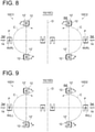
- FIGs. 7 to 9 are schematic planar views according to some embodiments.
- the slit forming device 10 (10B, 10C, 10D) is constituted by two slit forming devices.
- the slit forming device 10 (10B to 10D) is configured such that the movement trajectories (circumferences C) of the clampers 12 of the two slit forming devices are mirror symmetrical.
- arrows given to the movement trajectories C indicate the moving directions of the clampers 12, respectively.
- the two slit forming devices and the movement trajectories C of the clampers 12 are mirror symmetrical, downsized arrangement of the two slit forming devices is possible, and using the two slit forming devices, it is possible to increase processing efficiency of the works W.
- the two slit forming devices and the moving directions of the clampers 12 are mirror symmetrical. In another embodiment, the two slit forming devices and the moving directions of the clampers 12 may be the same.
- the slit forming device 10 (10B to 10D) sets a side without the processing stations being arranged as the inner side of the circumference C and places the processing stations 2st to 4st on the outer side of the circumference C, facilitating maintenance of the processing stations 2st to 4st.
- the slit forming device 10 (10B) shown in FIG. 7 is configured such that, in the loading station 2st, the clamper 12 indicated by a solid line is rotated by the clamper rotating part 16 (16a) in a direction of an arrow e to be set in the orientation of a clamper 12' indicated by a long dashed double-dotted line. That is, the rotation directions of the clampers 12 in the loading stations 2st between two slit forming devices 10B1 and 10B2 are mirror symmetrical as indicated by the arrows e.
- the clamper 12 indicated by the solid line is rotated by the clamper rotating part 16 (16b) in a direction of an arrow f to be set in the orientation of the clamper 12' indicated by the long dashed double-dotted line. That is, the rotation directions of the clampers 12 in the discharge stations 4st between the two slit forming devices 10B1 and 10B2 are mirror symmetrical as indicated by the arrows f.
- the clamper 12' After the clamper 12' receives the work W, the clamper 12' returns to the orientation of the clamper 12, and the clamper 12 moves toward the slit forming station 3st.
- the clamper 12' returns to the orientation of the clamper 12.
- the work W includes a right limb W(R) and a left limb W(L) of the bone-in limb meat
- the left limb W(L) is loaded to the slit forming device 10B1
- the right limb W(R) is loaded to the slit forming device 10B2.
- the left limb W(L) of the chicken thigh is to undergo slit formation.
- the slit forming surfaces S (meat surfaces) of both the right limb W(R) and the left limb W(L) face outward relative to a center line O (see FIG. 7 ).
- the works W are loaded to the loading station 2st upon 180-degree reverse of the hangers 26, and thus in the works W suspended by the clampers 12 in the loading stations 2st, the slit forming surfaces S (meat surfaces) of both the right limb W(R) and the left limb W(L) face the side of the center line O.
- the clamper 12 is rotated by the clamper rotating part 16 (16a) in the direction of the arrow e to be set in the orientation of the clamper 12', and the opening 12a faces the side of the hanger 26.
- the right limb W(R) and the left limb W(L) are each transferred from the hanger 26 to the clamper 12' of the loading station 2st in the unchanged orientation. Subsequently, when the clamper 12' moves from the loading station 2st to the slit forming station 3st, the rotation in the e direction in the loading station 2st is canceled, and the clamper 12' is set in the orientation of the clamper 12.
- the slit forming surfaces S (meat surfaces) of both the right limb W(R) and the left limb (L) are arranged to face the slit forming blades 14, respectively.
- the slit forming device 10 (10B) can be used as a dual purpose device capable of simultaneously processing the right limb W(R) and the left limb W(L) of the bone-in limb meats.
- the clampers 12 of the slit forming devices 10B1 and 10B2 are rotated in the f directions which are mirror symmetrical, the openings of both the clampers 12 can face in the outward direction suitable for discharge of the works W having undergone slit formation.
- the slit forming device 10 (10C) shown in FIG. 8 is configured such that rotation directions of the clampers 12 by the clamper rotating parts 16 (16a, 16b) of two slit forming devices 10C1 and 10C2 are the same direction. That is, as shown in the drawing, the slit forming device 10 (10C) is configured such that the rotation directions (e directions) of the clampers 12 in the loading stations 2st of the constituent two slit forming devices are the same, and the rotation directions (f directions) of the clampers 12 in the discharge stations 4st of the two slit forming devices are the same.
- the slit forming surface S (meat surface) of the right limb W(R) faces an opposite side of the bone portion (a reverse side of the drawing of FIG. 1 ).
- the slit forming surface S (meat surface) of the right limb W(R) suspended by the clamper 12' in the loading station 2st faces a front side of the bone portion (the front side in the drawing of FIG. 1 ; the left side in the drawing of FIG. 8 ). Therefore, when the clamper 12' moves from the loading station 2st to the slit forming station 3st, the rotation in the direction of the arrow e in the loading station 2st is canceled.
- the clamper 12' is set in the orientation of the clamper 12, and the slit forming surface S (meat surface) of the right limb W(R) is arranged to face the slit forming blade 14. Consequently, the skin surface is kept free from being cut in the slit forming station 3st, making it possible to avoid the decrease in commercial value of boneless meat.
- the slit forming device 10 (10C) can be used as an exclusive device capable of processing the right limb W(R) of the bone-in limb meat.
- Two slit forming devices 10D1 and 10D2 constituting the slit forming device 10 (10D) shown in FIG. 9 are also configured in the same manner. That is, the slit forming device 10 (10D) is configured such that rotation directions of the clampers 12 by the clamper rotating parts 16 (16a, 16b) of the two slit forming devices 10D1 and 10D2 are the same direction. As shown in the drawing, the slit forming device 10 (10D) is configured such that the rotation directions (e directions) of the clampers 12 in the loading stations 2st of the constituent two slit forming devices are the same, and the rotation directions (f directions) of the clampers 12 in the discharge stations 4st of the two slit forming devices are the same.
- the same operation as the slit forming device 10 (10C) is performed. That is, for example, when the knee joint portion N of the left limb W(L) is placed on the reception part 20 for each of the two slit forming devices 10D1 and 10D2 to face forward, the slit forming surface S (meat surface) of the left limb W(L) faces the front side of the bone portion (the front side of the drawing of FIG. 1 ; that is, the same side as FIG. 1 ).
- the slit forming surface S (meat surface) of the left limb W(L) suspended by the clamper 12' of the loading station 2st faces the opposite side of the bone portion (the opposite side in the drawing of FIG. 1 ; the right side in the drawing of FIG. 9 ). Therefore, when the clamper 12 moves from the loading station 2st to the slit forming station 3st, the rotation in the direction of the arrow e in the loading station 2st is canceled.
- the clamper 12 is set in the orientation of the clamper 12, and the slit forming surface S (meat surface) of the left limb (L) is arranged to face the slit forming blade 14. Therefore, the skin surface is kept free from being cut in the slit forming station 3st.
- the slit forming device 10 (10D) can be used as an exclusive device capable of processing the left limb W(L) of the bone-in limb meat.
- the clampers 12 of the two slit forming devices are rotated in the same direction to each be set in the orientation of clamper 12'.
- the openings of both the clampers 12' can face the outward direction suitable for discharge of the works W having undergone slit formation.
- the slit forming blade 14 is disposed on the outer circumference side of the slit forming station 3st.
- the slit forming blade 14 may be disposed on the radially outer side of the circumference C with respect to the slit forming station 3st. In this case, maintenance of the slit forming blade 14 becomes easier.
- the slit forming blade 14 may be disposed on the radially inner side of the circumference C with respect to the slit forming station 3st.
- the slit forming blade 14 may be disposed on the inner circumference side of the slit forming station 3st.
- a slit forming device (10 (10A, 10B, 10C, 10D)) includes a clamper (12) configured to pass through a plurality of stations (1st to 4st) arranged on a circumference (C), a slit forming blade (14) disposed on an outer circumference side or an inner circumference side of a slit forming station (3st) among the plurality of stations, and a clamper rotating part (16 (16a, 16b)) capable of rotating the clamper about a vertical line such that a slit forming surface (S) of a work (W) faces the slit forming blade in the slit forming station.
- a clamper (12) configured to pass through a plurality of stations (1st to 4st) arranged on a circumference (C), a slit forming blade (14) disposed on an outer circumference side or an inner circumference side of a slit forming station (3st) among the plurality of stations, and a clamper rotating part (16 (16a,
- the slit forming device (10) is the slit forming device defined in 1), where the plurality of stations (1st to 4st) include a loading station (2st) for the work (W) located upstream of the slit forming station (3st), and the clamper rotating part (16 (16a)) is configured to rotate the clamper such that a difference between a first angle ( ⁇ 1) and a second angle ( ⁇ 2) is not less than 80 degrees and not greater than 100 degrees, the first angle being formed by the slit forming surface (S) with respect to a tangent (t) direction to the circumference (C) in the loading station, the second angle being formed by the slit forming surface with respect to the tangent direction in the slit forming station (3st).
- the slit forming device (10) is the slit forming device defined in 2), where the first angle ( ⁇ 1) is in a direction orthogonal to the tangent (t) direction to the circumference (C), and the second angle ( ⁇ 2) is in a direction along the tangent direction to the circumference.
- the first angle is in the direction orthogonal to the tangent direction to the circumference, the work is loaded easily. Further, since the second angle is in the direction along the tangent direction to the circumference, it is possible to arrange the slit forming surface of the work to face the slit forming blade placed in the position radially deviated from the circumferential trajectory of the clamper.
- the slit forming device (10) is the slit forming device defined in any one of 1) to 3), where the plurality of stations (1st to 4st) include a discharge station (4st) for the work (W) located downstream of the slit forming station (3st), and the clamper rotating part (16 (16b)) is configured to rotate the clamper (12) such that a difference between a first angle ( ⁇ 1) and a third angle ( ⁇ 3) is not less than 80 degrees and not greater than 100 degrees, the first angle being formed by the slit forming surface (S) with respect to a tangent (t) direction to the circumference (C) in the slit forming station, the third angle ( ⁇ 3) being formed by the slit forming surface with respect to the tangent (t) direction in the discharge station (4st).
- the slit forming device (10) is the slit forming device defined in 4), where the third angle ( ⁇ 3) is in a direction orthogonal to the tangent (t) direction to the circumference (C).
- the slit forming device (10) is the slit forming device defined in any one of 1) to 5), where the clamper rotating part (16 (16a, 16b)) is configured to be able to switch a rotation direction of the clamper (22).
- the slit forming device (10) is the slit forming device defined in any one of 1) to 6), where two slit forming devices (10B1, 10B2, 10C1, 10C2, 10D1, 10D2) are arranged such that movement trajectories (C) of the clampers (22) are mirror symmetrical.
- the slit forming device (10) is the slit forming device defined in 7), where the slit forming device is configured such that, in two slit forming devices (10B1, 10B2), rotation directions of the clampers (22) by the clamper rotating parts (16 (16a, 16b)) are mirror symmetrical.
- the slit forming device when the work is bone-in limb meat including the right limb and the left limb, in a case where the slit forming device is used as a dual purpose device for forming a slit in the right limb by one slit forming device and for forming a slit in the left limb by the other bone-in limb meat, it is possible to arrange a desired slit forming surface to face the slit forming blade in each of both the slit forming devices.
- the slit forming device (10) is the slit forming device defined in 7), where the slit forming device is configured such that, in the two slit forming devices (10C1, 10C2, 10D1, 10D2), rotation directions of the clampers (22) by the clamper rotating parts (16 (16a, 16b)) are the same direction.
- the slit forming device is used as an exclusive device for forming a slit in one of the right limb or the left limb by the two slit forming devices, it is possible to arrange a desired slit forming surface to face the slit forming blade in each of both the slit forming devices.
- the slit forming device (10) is the slit forming device defined in any one of 1) to 9), where the slit forming blade (14) is disposed on the outer circumference side of the slit forming station (3st) among the plurality of stations (1st to 4st).
Landscapes
- Engineering & Computer Science (AREA)
- Life Sciences & Earth Sciences (AREA)
- Food Science & Technology (AREA)
- Wood Science & Technology (AREA)
- Zoology (AREA)
- Mechanical Engineering (AREA)
- Specific Conveyance Elements (AREA)
- Processing Of Meat And Fish (AREA)
- Control And Other Processes For Unpacking Of Materials (AREA)
- Details Of Cutting Devices (AREA)
- Re-Forming, After-Treatment, Cutting And Transporting Of Glass Products (AREA)
- Automatic Analysis And Handling Materials Therefor (AREA)
- Sawing (AREA)
- Dovetailed Work, And Nailing Machines And Stapling Machines For Wood (AREA)
- Auxiliary Devices For And Details Of Packaging Control (AREA)
- Confectionery (AREA)
- Electrical Discharge Machining, Electrochemical Machining, And Combined Machining (AREA)
Abstract
Description
- The present disclosure relates to a slit forming device.
- Slaughter work of a livestock carcass for meat is hard labor and is also inefficient if done manually, and thus has been automated. The present applicant has developed an automation technology in this field for a long time. Patent Document 1 proposes an automatic de-boning technique for bone-in meat, and Patent Document 2 proposes an automatic measurement technique of measuring the entire length of bone-in meat during conveyance. Further, Patent Document 3 proposes an automatic slit forming technique of forming a slit in bone-in meat during conveyance, and
Patent Document 4 proposes an automatic de-boning technique increased in processing efficiency. -
- Patent Document 1:
JP3483710B - Patent Document 2:
WO2019/131357A - Patent Document 3:
WO2019/131362A - Patent Document 4:
WO2019/131363A - As importance of meat increases, an automatic slaughter technique for meat is required of, for example, improvement in processing efficiency (such as an increase in number of processes per unit time), a downsized automation device, versatility, and further improvement in yield of meat portions.
- The present disclosure was made in view of the above, and an object of the present disclosure is to downsize a device for automating slit formation and to increase efficiency.
- In order to achieve the above object, a slit forming device according to the present disclosure includes a clamper configured to pass through a plurality of stations arranged on a circumference, a slit forming blade disposed on an outer circumference side or an inner circumference side of a slit forming station among the plurality of stations, and a clamper rotating part capable of rotating the clamper about a vertical line such that a slit forming surface of a work faces the slit forming blade in the slit forming station.
- In the present specification, "work" refers to bone-in meat obtained by slaughtering a livestock carcass for meat or bone-in meat (for example, bone-in limb meat such as arm meat or thigh meat) in the middle of slaughtering.
- According to a slit forming device according to the present disclosure, it is possible to downsize a device for automating a slit forming step and to improve processing efficiency.
-
-
FIG. 1 is a side view of a slit forming device according to an embodiment. -
FIG. 2 is a front view where a part of the slit forming device is omitted according to an embodiment (taken along line A-A inFIG. 1 ). -
FIG. 3 is a schematic plan view of the slit forming device according to an embodiment. -
FIG. 4 is a cross-sectional view taken along line B-B inFIG. 2 . -
FIG. 5 is a schematic perspective view for describing an operation of a cam member according to an embodiment. -
FIG. 6 is a schematic planar view for describing the operation of the cam member according to an embodiment. -
FIG. 7 is a schematic planar view of the slit forming device according to an embodiment. -
FIG. 8 is a schematic planar view of the slit forming device according to an embodiment. -
FIG. 9 is a schematic planar view of the slit forming device according to an embodiment. - Some embodiments of the present invention will be described below with reference to the accompanying drawings. It is intended, however, that unless particularly specified, dimensions, materials, shapes, relative positions and the like of components described or shown in the drawings as the embodiments shall be interpreted as illustrative only and not intended to limit the scope of the present invention.
- For instance, an expression of relative or absolute arrangement such as "in a direction", "along a direction", "parallel", "orthogonal", "centered", "concentric" and "coaxial" shall not be construed as indicating only the arrangement in a strict literal sense, but also includes a state where the arrangement is relatively displaced by a tolerance, or by an angle or a distance whereby it is possible to achieve the same function.
- For instance, an expression of an equal state such as "same", "equal", and "uniform" shall not be construed as indicating only the state in which the feature is strictly equal, but also includes a state in which there is a tolerance or a difference that can still achieve the same function.
- Further, for instance, an expression of a shape such as a rectangular shape or a tubular shape shall not be construed as only the geometrically strict shape, but also includes a shape with unevenness or chamfered corners within the range in which the same effect can be achieved.
- On the other hand, an expressions such as "comprising", "including", "having", "containing", and "constituting" one constitutional element are not intended to be exclusive of other constitutional elements.
-
FIGs. 1 to 3 each show a slit forming device 10 (10A) according to an embodiment.FIG. 1 is a side view of the slit forming device 10 (10A),FIG. 2 is a front view taken along line A-A inFIG. 1 , andFIG. 3 is a schematic plan view of the slit forming device 10 (10A). - As shown in
FIG. 3 , the slit forming device 10 (10A) includes a plurality of processing stations 1st to 4st arranged on a circumference C. Aclamper 12 has a movement trajectory moving on the circumference C, and can pass through the plurality of stations while suspending a work W. Among the plurality of stations, the slit forming station 3st includes aslit forming blade 14 disposed on the outer side or inner side of the circumference C, and a clamper rotating part 16 (16a, 16b) capable of rotating theclamper 12 about a vertical line P. Theclamper rotating part 16 is configured to be able to rotate theclamper 12 about the vertical line such that a slit forming surface S of the work W faces theslit forming blade 14 in the slit forming station 3st. - In an embodiment, the slit forming device 10 (10A) includes the loading station 2st upstream of the slit forming station 3st, and includes the discharge station 4st downstream of the slit forming station 3st. The
clamper rotating part 16 includes the clamper rotating part 16 (16a) disposed in the loading station 2st, and the clamper rotating part 16 (16b) disposed in the discharge station 4st. As shown inFIG. 3 , theclamper 12 has anopening 12a where the work W is to be loaded, and the orientation of the opening 12a is set such that the slit forming surface S faces theslit forming blade 14 in the slit forming station 3st, by rotating theclamper 12 about the vertical line P with the clamper rotating part 16 (16a). - The orientation of the slit forming surface S of the work W suspended by the
clamper 12 and the orientation of the opening 12a of theclamper 12 are uniquely associated with each other, and once the angle of the opening 12a with respect to a tangent t to the circumference C is decided, the angle of the slit forming surface S with respect to the tangent t is uniquely decided. - Thus, since the plurality of stations 1st to 4st are arranged along the circumference C, it is possible to achieve downsized layout of the slit forming device 10 (10A). Further, with the
clamper rotating part 16, with respect to theslit forming blade 14 placed in a position radially deviated from the circumferential movement trajectory of theclamper 12, it is possible to rotate theclamper 12 such that the slit forming surface S of the work W faces theslit forming blade 14. Thus, it is possible to reliably perform slit formation on the slit forming surface S, making it possible to improve processing efficiency (such as an increase in processing numbers per unit time). - In an embodiment, as shown in
FIGs. 1 and3 , the slit forming device 10 (10A) includes the transfer station 1 st for loading the work W to the loading station 2st. The transfer station 1st loads the work W transferred by a work conveyance device (not shown) to the stoppedclamper 12 in the loading station 2st. The transfer station 1st includes areception part 20 for receiving the work W from the above-described work conveyance device, and atransfer part 22 for loading the work W received by thereception part 20 to the stoppedclamper 12 in the loading station 2st. Thereception part 20 has aslot 20a formed in the axial direction and pushes out, by a pusher (not shown) or the like, the work W suspended in theslot 20a to thetransfer part 22. - As shown in
FIG. 1 , thetransfer part 22 includes arotational shaft 24 disposed in the vertical direction, a plurality ofhangers 26 disposed around therotational shaft 24, and amotor 28 for rotating therotational shaft 24. In eachhanger 26, arecess 26a where the work W is to be inserted and suspended is formed in the axial direction. Thehanger 26 having received the work W from thereception part 20 is reversed by 180° to face theclamper 12 waiting in the loading station 2st, and transfers the work W to theclamper 12. In order to prevent the work W from falling off therecess 26a during the rotation of thehanger 26, asemi-circular guard ring 30 is provided. - In the upper part of a body portion of the slit forming device 10 (10A), a
circular feed ring 32 is disposed in the horizontal direction. Thefeed ring 32 is configured to be rotatable about a vertical center axis by a drive device (not shown). A plurality ofsupport shafts 33 are vertically disposed in the circumferential direction of thefeed ring 32. Eachsupport shaft 33 is supported to be lifted/lowered via abracket 36 with respect to a pair ofguide bars 34 mounted on thefeed ring 32. Theclamper 12 is disposed at a lower end of eachsupport shaft 33, and is sent with tact feed so as to be paused in each station by the above-described drive device. - In the exemplary embodiments shown in
FIGs. 1 to 3 , the loading station 2st, the slit forming station 3st, and the discharge station 4st are disposed at intervals of 90°, and an interval between the discharge station 4st and the loading station 2st is at 180°. Then, the work W is loaded to theclamper 12 in the loading station 2st, the slit forming step is performed in the slit forming station 3st, and the work W having undergone slit formation is discharged in the discharge station 4st. - As shown in
FIG. 1 , the clamper rotating part 16 (16a, 16b) includes anair cylinder 40 mounted on a fixed support part (not shown), and acam member 44 is mounted on a tip portion of apiston 42 of theair cylinder 40. On the other hand, thesupport shaft 33 has a double shaft structure inside of which arotatable shaft 46 rotatable about the shaft is concentrically disposed, and theclamper 12 is mounted at a lower end of therotatable shaft 46 and is configured to be rotatable about the shaft together with therotatable shaft 46. -
FIG. 4 is a cross-sectional view taken along line B-B inFIG. 2 . Referring toFIG. 4 , in an upper end portion of therotatable shaft 46, aswing roller 48 is disposed integrally with therotatable shaft 46 via anarm 49, and theswing roller 48 is rotatable about therotatable shaft 46. Further, in the upper end portion of thesupport shaft 33, aclasp 50 is disposed integrally with thesupport shaft 33, as well as acoil spring 52 is wound around therotatable shaft 46, and one end of thecoil spring 52 is connected to theclasp 50. - As shown in
FIG. 2 , thecam member 44 is mounted on the tip portion of thepiston 42 to be rotatable about ashaft 42a, and is mounted to be rotatable about ashaft 54a which is disposed on asupport plate 54 mounted on the fixed support part (not shown). Thus, if thepiston 42 extends, thecam member 44 rotates about theshaft 54a, moves downward, and hits against theswing roller 48, causing theswing roller 48 to rotate about therotatable shaft 46. Then, therotatable shaft 46 rotates about the shaft together with theswing roller 48. Consequently, theclamper 12 also rotates about the vertical line P together with therotatable shaft 46. If thepiston 42 retreats, and thecam member 44 retreats upward, theswing roller 48 returns to a position before rotation by a spring force of thecoil spring 52. - In an embodiment, the
slit forming device 10 includes a lifting/lowering means for lifting/lowering theclamper 12 at a predetermined height at a predetermined position. For example, as the lifting/lowering means, thebracket 36 includes a lifting/loweringroller slit forming device 10, equipment such as a drive device (not shown) for thefeed ring 32 is disposed, and an outer plate (not shown) is provided to enclose the equipment. In the outer plate, a traveling path (not shown) for allowing the lifting/loweringroller roller rotatable shaft 46 and the clamper 12 (see Patent Document 1). - In an embodiment, as shown in
FIG. 1 , theslit forming device 10 includes achuck 60 rotatably disposed on theclamper 12, for opening/closing theopening 12a of theclamper 12, and abar 62 disposed integrally with thechuck 60. On the circumference C, a contact piece (not shown) contacting thebar 62 to rotate thechuck 60 is disposed. The contact piece contacts thebar 62 when theclamper 12 moves on the circumference C, operating thechuck 60 to open/close theopening 12a. Thus, theopening 12a is opened in the loading station 2st and the discharge station 4st to allow for loading and discharge of the work W, and theopening 12a is closed in the slit forming station 3st to prevent the work W from falling off. - In another embodiment, a control device for controlling a drive device for the
chuck 60 is provided, and the control device may control an opening/closing timing of thechuck 60. - In an embodiment, as shown in
FIG. 3 , in the loading station 2st, when the work W is loaded from the transfer station 1st to theclamper 12, theclamper 12 is rotated by the clamper rotating part 16 (16a) in a direction of 12' indicated by a double-dotted chain line, and theopening 12a faces outward relative to the circumference C. Theclamper rotating part 16 controls a rotation angle of theclamper 12 such that a difference between a first angle θ1, which is formed by the slit forming surface S with respect to the direction of the tangent t to the circumference C in the loading station 2st, and a second angle θ2, which is formed by the slit forming surface S with respect to the direction of the tangent t to the circumference C in the slit forming station 3st, falls within 80° to 100°. - In an embodiment, the first angle θ1 may change in accordance with the operation of the
clamper rotating part 16 in the loading station 2st. Likewise, the second angle θ2 may change in accordance with the operation of theclamper rotating part 16 in the slit forming station 3st. In this case, it is only necessary that the difference between the first angle θ1 while the work W is loaded to the loading station 2st and the second angle θ2 while the slit forming surface S faces theslit forming blade 14 falls within 80° to 100°. For example, it is only necessary that a value obtained by subtracting the second angle θ2 from the first angle θ1 falls within 80° to 100°. - In the present specification, "upstream" or "downstream" means upstream of a moving direction of the
clamper 12 or downstream of the moving direction of theclamper 12. - According to the present embodiment, in the loading station 2st and the slit forming station 3st, it is possible to orient the slit forming surface S of the work W at the angle suitable for the processing operation in each of these stations, making it possible to improve working efficiency.
- In the loading station 2st, the slit forming device 10 (10A) operates the clamper rotating part 16 (16a) to rotate the
swing roller 48 by thecam member 44, thereby setting the slit forming surface S at the first angle θ1. In the slit forming station 3st, the slit forming device 10 (10A) sets the slit forming surface S at the second angle θ2 by an elastic force of thecoil spring 52 applied to theswing roller 48, without operating the clamper rotating part 16 (16a). - In an embodiment, the work W refers to bone-in meat (such as arm meat or thigh meat) obtained by slaughtering or in the middle of slaughtering a livestock carcass for meat. Then, an ankle portion is inserted into the
slot 20a of theclamper 12 to be suspended. In the exemplary embodiments shown inFIGs. 1 and3 , the work W is chicken thigh. The bone-in limb meat has one surface which is a first surface (meat surface) where meat is exposed, and another surface which is a second surface (skin surface) covered with skin. If the skin on the skin surface is cut in the slit forming step, a commercial value of boneless meat is decreased. Thus, in the slit forming station 3st, it is necessary that the meat surface faces theslit forming blade 14 to be cut by theslit forming blade 14. According to the above embodiment, it is possible to cause the meat surface to face theslit forming blade 14 by the clamper rotating part 16 (16a). If the work W is the bone-in limb meat, the first surface and the second surface of the bone-in limb meat suspended by theclamper 12, and theopening 12a face the same direction. - In an embodiment, as shown in
FIG. 3 , the first angle θ1 of the slit forming surface S in the loading station 2st is in a 90° direction orthogonal to the direction of the tangent t to the circumference C, and the second angle θ2 of the slit forming surface S in the slit forming station 3st is in a direction along the direction of the tangent t to the circumference C, that is 0°. According to the present embodiment, since the first angle θ1 is 90° in the loading station 2st, the work W is easily loaded to theclamper 12. Further, since the second angle θ2 is 0° in the slit forming station 3st, it is possible to arrange the work W such that the slit forming surface S of the work W faces theslit forming blade 14 placed in the position radially deviated from the circumferential trajectory of theclamper 12. Accordingly, it is possible to perform slit formation accurately and efficiently. - In an embodiment, in the loading station 2st, the slit forming device 10 (10A) rotates the
swing roller 48 by thecam member 44, thereby setting the first angle θ1 at 90°. Then, in the slit forming station 3st, the slit forming device 10 (10A) sets the second angle θ2 formed by the slit forming surface S always at 0° by keeping therotatable shaft 46 applied with the elastic force of thecoil spring 52, without rotating theswing roller 48 by thecam member 44. - In an embodiment, as shown in
FIG. 3 , the slit forming device 10 (10A) includes the discharge station 4st downstream of the slit forming station 3st and performs an operation of discharging the work W having undergone slit formation in the discharge station 4st. The clamper rotating part 16 (16b) controls the slit forming surface S to have a third angle θ3 in the discharge station 4st, and rotates theclamper 12 such that a difference between the second angle θ2 and the third angle θ3 formed by the slit forming surface S in the discharge station 4st falls within 80° to 100°. According to the present embodiment, in the discharge station 4st, it is possible to orient the work W at the angle suitable for the discharge operation, facilitating the discharge operation. Therefore, it is possible to improve processing efficiency of the slit forming device 10 (10A). - The third angle θ3 may change in accordance with the operation of the
clamper rotating part 16 in the discharge station 4st. In this case, it is only necessary that the difference between the second angle θ2 and the third angle θ3 while the work W is discharged in the discharge station 4st falls within 80° to 100°. For example, it is only necessary that a value obtained by subtracting the second angle θ2 from the third angle θ3 falls within 80° to 100°. - The third angle θ3 may be the same as the first angle θ1. Thus, the
clamper rotating part 16 can be operated easily. - In an embodiment, in the slit forming station 3st, the slit forming device 10 (10A) sets the slit forming surface S at the second angle θ2 by the elastic force of the
coil spring 52 applied to theswing roller 48, without operating the clamper rotating part 16 (16a). In the discharge station 4st, the slit forming device 10 (10A) operates the clamper rotating part 16 (16a) to rotate theswing roller 48 by thecam member 44, thereby setting the slit forming surface S at the third angle θ3. - In an embodiment, the third angle θ3 is in a direction orthogonal to a tangent direction to the circumference C. Thus, the
opening 12a of theclamper 12 faces outward relative to the circumference C, facilitating discharge of the work W having undergone slit formation. - In an embodiment, in the discharge station 4st, the slit forming device 10 (10A) operates the clamper rotating part 16 (16b), lowers the
cam member 44, and rotates theswing roller 48, thereby setting the third angle θ3 at 90°. - In an embodiment, the
clamper rotating part 16 is configured to be able to switch a rotation direction of theclamper 12. When the work W is bone-in limb meat including a right limb and a left limb, the presence of the meat surface and the skin surface is reversed with respect to a bone portion between the right limb and the left limb. According to the present embodiment, since the rotation direction of theclamper 12 is switchable, it is possible to always arrange the meat surface, as the slit forming surface S, to face theslit forming blade 14 even if the work W suspended by theclamper 12 includes the right limb and the left limb. Thus, it is possible to form slits in the right limb and the left limb, respectively. - In
FIG. 4 , for example, in the loading station 2st, if theclamper 12 is rotated, the clamper rotating part 16 (16a) is operated to move thecam member 44 in a direction of an arrow a. Thecam member 44 rotates theswing roller 48 around the vertical axis of the rotatable shaft 46 (such as 90°), and rotates theswing roller 48 to a position of a swing roller 48'. If theclamper 12 is rotated in a backward direction, thecam member 44 is relocated at a position of 44', as well as theswing roller 48 is relocated at a position of 48". Then, the clamper rotating part 16 (16a) is operated to move the cam member 44' to a direction of an arrow b, and to move theswing roller 48" in an opposite direction to theswing roller 48. -
FIGs. 5 and6 each show an aspect in which thecam member 44 pushes theswing roller 48 to rotate about therotatable shaft 46.FIG. 5 is a schematic perspective view, andFIG. 6 is a schematic planar view showing the operation of thecam member 44 in sequence. - As shown in
FIGs. 5 and6 , operating theclamper rotating part 16, thecam member 44 moves in a direction of an arrow c (downward in the drawing ofFIG. 5 ) centering around theshaft 54a, and approaches theswing roller 48. Subsequently, first, abottom surface 44a of thecam member 44 contacts theswing roller 48, and theswing roller 48 is rotated about therotatable shaft 46 in a direction of an arrow d. Next, as thecam member 44 moves, a contact surface with theswing roller 48 is shifted from thebottom surface 44a to aside surface 44b. While thecam member 44 contacts theswing roller 48, theswing roller 48 is rotated about the vertical line P by a predetermined angle. If thepiston 42 retreats, and thecam member 44 is lifted and separated from theswing roller 48, theswing roller 48 returns to the position before rotation relative to therotatable shaft 46 by the elastic force of thecoil spring 52. -
FIGs. 7 to 9 are schematic planar views according to some embodiments. InFIGs. 7 to 9 , the slit forming device 10 (10B, 10C, 10D) is constituted by two slit forming devices. The slit forming device 10 (10B to 10D) is configured such that the movement trajectories (circumferences C) of theclampers 12 of the two slit forming devices are mirror symmetrical. InFIGs. 7 to 9 , arrows given to the movement trajectories C indicate the moving directions of theclampers 12, respectively. According to the present embodiments, since the two slit forming devices and the movement trajectories C of theclampers 12 are mirror symmetrical, downsized arrangement of the two slit forming devices is possible, and using the two slit forming devices, it is possible to increase processing efficiency of the works W. - In
FIGs. 7 to 9 , the two slit forming devices and the moving directions of theclampers 12 are mirror symmetrical. In another embodiment, the two slit forming devices and the moving directions of theclampers 12 may be the same. - In an embodiment, the slit forming device 10 (10B to 10D) sets a side without the processing stations being arranged as the inner side of the circumference C and places the processing stations 2st to 4st on the outer side of the circumference C, facilitating maintenance of the processing stations 2st to 4st.
- The slit forming device 10 (10B) shown in
FIG. 7 is configured such that, in the loading station 2st, theclamper 12 indicated by a solid line is rotated by the clamper rotating part 16 (16a) in a direction of an arrow e to be set in the orientation of a clamper 12' indicated by a long dashed double-dotted line. That is, the rotation directions of theclampers 12 in the loading stations 2st between two slit forming devices 10B1 and 10B2 are mirror symmetrical as indicated by the arrows e. Further, in the discharge station 4st, theclamper 12 indicated by the solid line is rotated by the clamper rotating part 16 (16b) in a direction of an arrow f to be set in the orientation of the clamper 12' indicated by the long dashed double-dotted line. That is, the rotation directions of theclampers 12 in the discharge stations 4st between the two slit forming devices 10B1 and 10B2 are mirror symmetrical as indicated by the arrows f. In the loading station 2st, after the clamper 12' receives the work W, the clamper 12' returns to the orientation of theclamper 12, and theclamper 12 moves toward the slit forming station 3st. In the discharge station 4st, after the clamper 12' discharges the work W, the clamper 12' returns to the orientation of theclamper 12. - If the work W includes a right limb W(R) and a left limb W(L) of the bone-in limb meat, the left limb W(L) is loaded to the slit forming device 10B1, and the right limb W(R) is loaded to the slit forming device 10B2. When the works W are placed on the
reception parts 20 of the transfer stations 1st in the same orientation (that is, when knee joint portions N are placed in the same direction) in the slit forming devices 10B1 and 10B2, the meat surfaces, which are the slit forming surfaces S, are reversed with respect to the bone portions between the right limb W(R) and the left limb W(L). As a side note, in the exemplary embodiments shown inFIGs. 1 and2 , as the work W, the left limb W(L) of the chicken thigh is to undergo slit formation. For example, as shown inFIG. 1 , when the knee joint portions N of the right limb W(R) and the left limb W(L) are placed on thereception parts 20 to face forward, in the slit forming device 10 (10B), the slit forming surfaces S (meat surfaces) of both the right limb W(R) and the left limb W(L) face outward relative to a center line O (seeFIG. 7 ). - Subsequently, the works W are loaded to the loading station 2st upon 180-degree reverse of the
hangers 26, and thus in the works W suspended by theclampers 12 in the loading stations 2st, the slit forming surfaces S (meat surfaces) of both the right limb W(R) and the left limb W(L) face the side of the center line O. At this time, in the loading station 2st for each of the slit forming devices 10B1 and 10B2, theclamper 12 is rotated by the clamper rotating part 16 (16a) in the direction of the arrow e to be set in the orientation of the clamper 12', and theopening 12a faces the side of thehanger 26. - The right limb W(R) and the left limb W(L) are each transferred from the
hanger 26 to the clamper 12' of the loading station 2st in the unchanged orientation. Subsequently, when the clamper 12' moves from the loading station 2st to the slit forming station 3st, the rotation in the e direction in the loading station 2st is canceled, and the clamper 12' is set in the orientation of theclamper 12. Thus, the slit forming surfaces S (meat surfaces) of both the right limb W(R) and the left limb (L) are arranged to face theslit forming blades 14, respectively. Consequently, the skin surface is kept free from being cut in the slit forming step, making it possible to avoid the decrease in commercial value of boneless meat. The slit forming device 10 (10B) can be used as a dual purpose device capable of simultaneously processing the right limb W(R) and the left limb W(L) of the bone-in limb meats. - Further, in the discharge stations 4st, since the
clampers 12 of the slit forming devices 10B1 and 10B2 are rotated in the f directions which are mirror symmetrical, the openings of both theclampers 12 can face in the outward direction suitable for discharge of the works W having undergone slit formation. - The slit forming device 10 (10C) shown in
FIG. 8 is configured such that rotation directions of theclampers 12 by the clamper rotating parts 16 (16a, 16b) of two slit forming devices 10C1 and 10C2 are the same direction. That is, as shown in the drawing, the slit forming device 10 (10C) is configured such that the rotation directions (e directions) of theclampers 12 in the loading stations 2st of the constituent two slit forming devices are the same, and the rotation directions (f directions) of theclampers 12 in the discharge stations 4st of the two slit forming devices are the same. - In the case of the slit forming device 10 (10C), for example, when the knee joint portion N of the right limb W(R) is placed on the
reception part 20 for each of the two slit forming devices 10C1 and 10C2 to face forward, the slit forming surface S (meat surface) of the right limb W(R) faces an opposite side of the bone portion (a reverse side of the drawing ofFIG. 1 ). Thus, when thereception part 20 is rotated by 180°, and the right limb W(R) is loaded to the clamper 12' in the loading station 2st, the slit forming surface S (meat surface) of the right limb W(R) suspended by the clamper 12' in the loading station 2st faces a front side of the bone portion (the front side in the drawing ofFIG. 1 ; the left side in the drawing ofFIG. 8 ). Therefore, when the clamper 12' moves from the loading station 2st to the slit forming station 3st, the rotation in the direction of the arrow e in the loading station 2st is canceled. Thus, the clamper 12' is set in the orientation of theclamper 12, and the slit forming surface S (meat surface) of the right limb W(R) is arranged to face theslit forming blade 14. Consequently, the skin surface is kept free from being cut in the slit forming station 3st, making it possible to avoid the decrease in commercial value of boneless meat. Thus, the slit forming device 10 (10C) can be used as an exclusive device capable of processing the right limb W(R) of the bone-in limb meat. - Two slit forming devices 10D1 and 10D2 constituting the slit forming device 10 (10D) shown in
FIG. 9 are also configured in the same manner. That is, the slit forming device 10 (10D) is configured such that rotation directions of theclampers 12 by the clamper rotating parts 16 (16a, 16b) of the two slit forming devices 10D1 and 10D2 are the same direction. As shown in the drawing, the slit forming device 10 (10D) is configured such that the rotation directions (e directions) of theclampers 12 in the loading stations 2st of the constituent two slit forming devices are the same, and the rotation directions (f directions) of theclampers 12 in the discharge stations 4st of the two slit forming devices are the same. - When the left limbs W(L) are placed on the
reception parts 20 of the two slit forming devices 10D1 and 10D2 with the knee joint portion N facing forward, the same operation as the slit forming device 10 (10C) is performed. That is, for example, when the knee joint portion N of the left limb W(L) is placed on thereception part 20 for each of the two slit forming devices 10D1 and 10D2 to face forward, the slit forming surface S (meat surface) of the left limb W(L) faces the front side of the bone portion (the front side of the drawing ofFIG. 1 ; that is, the same side asFIG. 1 ). Thus, when the left limb W(L) is reversed and loaded to the clamper 12' of the loading station 2st, the slit forming surface S (meat surface) of the left limb W(L) suspended by the clamper 12' of the loading station 2st faces the opposite side of the bone portion (the opposite side in the drawing ofFIG. 1 ; the right side in the drawing ofFIG. 9 ). Therefore, when theclamper 12 moves from the loading station 2st to the slit forming station 3st, the rotation in the direction of the arrow e in the loading station 2st is canceled. Thus, theclamper 12 is set in the orientation of theclamper 12, and the slit forming surface S (meat surface) of the left limb (L) is arranged to face theslit forming blade 14. Therefore, the skin surface is kept free from being cut in the slit forming station 3st. Thus, the slit forming device 10 (10D) can be used as an exclusive device capable of processing the left limb W(L) of the bone-in limb meat. - Further, in the slit forming device 10 (10C, 10D), in the discharge stations 4st as well, the
clampers 12 of the two slit forming devices are rotated in the same direction to each be set in the orientation of clamper 12'. Thus, the openings of both the clampers 12' can face the outward direction suitable for discharge of the works W having undergone slit formation. - In an embodiment, as shown in
FIGs. 3 and7 to 9 , theslit forming blade 14 is disposed on the outer circumference side of the slit forming station 3st. Thus, maintenance of theslit forming blade 14 becomes easy. Alternatively, theslit forming blade 14 may be disposed on the radially outer side of the circumference C with respect to the slit forming station 3st. In this case, maintenance of theslit forming blade 14 becomes easier. Note that theslit forming blade 14 may be disposed on the radially inner side of the circumference C with respect to the slit forming station 3st. - In another embodiment, the
slit forming blade 14 may be disposed on the inner circumference side of the slit forming station 3st. - The contents described in the above embodiments would be understood as follows, for instance.
- 1) A slit forming device (10 (10A, 10B, 10C, 10D)) according to one aspect includes a clamper (12) configured to pass through a plurality of stations (1st to 4st) arranged on a circumference (C), a slit forming blade (14) disposed on an outer circumference side or an inner circumference side of a slit forming station (3st) among the plurality of stations, and a clamper rotating part (16 (16a, 16b)) capable of rotating the clamper about a vertical line such that a slit forming surface (S) of a work (W) faces the slit forming blade in the slit forming station.
- With the above configuration, in order to achieve downsized layout, in a case where the slit forming blade is placed in a position radially deviated from the circumferential trajectory of the clamper, it is possible to reliably form a slit in the slit forming surface of the work, by rotating the clamper such that the slit forming surface faces the slit forming blade. Thus, it is possible to downsize a device for automating a slit forming step and to improve processing efficiency.
- 2) The slit forming device (10) according to another aspect is the slit forming device defined in 1), where the plurality of stations (1st to 4st) include a loading station (2st) for the work (W) located upstream of the slit forming station (3st), and the clamper rotating part (16 (16a)) is configured to rotate the clamper such that a difference between a first angle (θ1) and a second angle (θ2) is not less than 80 degrees and not greater than 100 degrees, the first angle being formed by the slit forming surface (S) with respect to a tangent (t) direction to the circumference (C) in the loading station, the second angle being formed by the slit forming surface with respect to the tangent direction in the slit forming station (3st).
- With the above configuration, in the loading station and the slit forming station, it is possible to orient the slit forming surface of the work at the angle suitable for the processing operation in each of these stations, making it possible to improve working efficiency.
- 3) The slit forming device (10) according to still another aspect is the slit forming device defined in 2), where the first angle (θ1) is in a direction orthogonal to the tangent (t) direction to the circumference (C), and the second angle (θ2) is in a direction along the tangent direction to the circumference.
- With the above configuration, since the first angle is in the direction orthogonal to the tangent direction to the circumference, the work is loaded easily. Further, since the second angle is in the direction along the tangent direction to the circumference, it is possible to arrange the slit forming surface of the work to face the slit forming blade placed in the position radially deviated from the circumferential trajectory of the clamper.
- 4) The slit forming device (10) according to yet another aspect is the slit forming device defined in any one of 1) to 3), where the plurality of stations (1st to 4st) include a discharge station (4st) for the work (W) located downstream of the slit forming station (3st), and the clamper rotating part (16 (16b)) is configured to rotate the clamper (12) such that a difference between a first angle (θ1) and a third angle (θ3) is not less than 80 degrees and not greater than 100 degrees, the first angle being formed by the slit forming surface (S) with respect to a tangent (t) direction to the circumference (C) in the slit forming station, the third angle (θ3) being formed by the slit forming surface with respect to the tangent (t) direction in the discharge station (4st).
- With the above configuration, in the discharge station, when the work having undergone slit formation is discharged, it is possible to arrange the work at the angle suitable for the discharge operation.
- 5) The slit forming device (10) according to yet another aspect is the slit forming device defined in 4), where the third angle (θ3) is in a direction orthogonal to the tangent (t) direction to the circumference (C).
- With the above configuration, since the third angle is in the direction orthogonal to the tangent direction to the circumference, the work having undergone slit formation is easily discharged.
- 6) The slit forming device (10) according to yet another aspect is the slit forming device defined in any one of 1) to 5), where the clamper rotating part (16 (16a, 16b)) is configured to be able to switch a rotation direction of the clamper (22).
- With the above configuration, when the work is bone-in limb meat including the right limb W(R) and the left limb W(L), slit formation for both of the right limb and the left limb is possible.
- 7) The slit forming device (10) according to yet another aspect is the slit forming device defined in any one of 1) to 6), where two slit forming devices (10B1, 10B2, 10C1, 10C2, 10D1, 10D2) are arranged such that movement trajectories (C) of the clampers (22) are mirror symmetrical.
- With the above configuration, since the movement trajectories of the clampers in the two slit forming devices are mirror symmetrical, downsized arrangement is possible, and using the two slit forming devices, it is possible to increase processing efficiency.
- 8) The slit forming device (10) according to yet another aspect is the slit forming device defined in 7), where the slit forming device is configured such that, in two slit forming devices (10B1, 10B2), rotation directions of the clampers (22) by the clamper rotating parts (16 (16a, 16b)) are mirror symmetrical.
- With the above configuration, when the work is bone-in limb meat including the right limb and the left limb, in a case where the slit forming device is used as a dual purpose device for forming a slit in the right limb by one slit forming device and for forming a slit in the left limb by the other bone-in limb meat, it is possible to arrange a desired slit forming surface to face the slit forming blade in each of both the slit forming devices.
- 9) The slit forming device (10) according to yet another aspect is the slit forming device defined in 7), where the slit forming device is configured such that, in the two slit forming devices (10C1, 10C2, 10D1, 10D2), rotation directions of the clampers (22) by the clamper rotating parts (16 (16a, 16b)) are the same direction.
- With the above configuration, in a case where the work is bone-in limb meat, and the slit forming device is used as an exclusive device for forming a slit in one of the right limb or the left limb by the two slit forming devices, it is possible to arrange a desired slit forming surface to face the slit forming blade in each of both the slit forming devices.
- 10) The slit forming device (10) according to yet another aspect is the slit forming device defined in any one of 1) to 9), where the slit forming blade (14) is disposed on the outer circumference side of the slit forming station (3st) among the plurality of stations (1st to 4st).
- With the above configuration, since the slit forming blade is disposed on the outer circumference side of the slit forming station, maintenance of the slit forming blade becomes easy.
-
- 10 (10A, 10B, 10C, 10D), 10B1, 10B2, 10C1, 10C2, 10D1, 10D2 Slit forming device 1st Transfer station
- 2st Loading station
- 3st Slit forming station
- 12, 12' Clamper
- 12a Opening
- 14 Slit forming blade
- 16 (16a, 16b) Clamper rotating part
- 20 Reception part
- 22a Slot
- 22 Transfer part
- 24 Rotational shaft
- 26 Hanger
- 26a Recess
- 28 Motor
- 30 Guard ring
- 32 Feed ring
- 33 Support shaft
- 34 Guide bar
- 36 Bracket
- 40 Air cylinder
- 42 Piston
- 42a Shaft
- 44, 44' Cam member
- 46 Rotatable shaft
- 48, 48', 48" Swing roller
- 49 Arm
- 50 Clasp
- 52 Coil spring
- 54 Support plate
- 54a Shaft
- 56, 58 Lifting/lowering roller
- 60 Chuck
- 62 Bar
- C Circumference (movement trajectory)
- O Center line
- N Knee joint portion
- P Vertical line
- S Slit forming surface
- W Work
- W(R) Right limb
- W(L) Left limb
- t Tangent
- θ1 First angle
- θ2 Second angle
- θ3 Third angle
Claims (10)
- A slit forming device, comprising:a clamper configured to pass through a plurality of stations arranged on a circumference;a slit forming blade disposed on an outer circumference side or an inner circumference side of a slit forming station among the plurality of stations; anda clamper rotating part capable of rotating the clamper about a vertical line such that a slit forming surface of a work faces the slit forming blade in the slit forming station.
- The slit forming device according to claim 1,wherein the plurality of stations include a loading station for the work located upstream of the slit forming station, andwherein the clamper rotating part is configured to rotate the clamper such that a difference between a first angle and a second angle is not less than 80 degrees and not greater than 100 degrees, the first angle being formed by the slit forming surface with respect to a tangent direction to the circumference in the loading station, the second angle being formed by the slit forming surface with respect to the tangent direction in the slit forming station.
- The slit forming device according to claim 2,wherein the first angle is in a direction orthogonal to the tangent direction to the circumference, andwherein the second angle is in a direction along the tangent direction to the circumference.
- The slit forming device according to any one of claims 1 to 3,wherein the plurality of stations include a discharge station for the work located downstream of the slit forming station, andwherein the clamper rotating part is configured to rotate the clamper such that a difference between a first angle and a third angle is not less than 80 degrees and not greater than 100 degrees, the first angle being formed by the slit forming surface with respect to a tangent direction to the circumference in the slit forming station, the third angle being formed by the slit forming surface with respect to the tangent direction in the discharge station.
- The slit forming device according to claim 4,
wherein the third angle is in a direction orthogonal to the tangent direction to the circumference. - The slit forming device according to any one of claims 1 to 5,
wherein the clamper rotating part is configured to be able to switch a rotation direction of the clamper. - The slit forming device according to any one of claims 1 to 6,
wherein two slit forming devices are arranged such that movement trajectories of the clampers are mirror symmetrical. - The slit forming device according to claim 7,
wherein the slit forming device is configured such that, in two slit forming devices, rotation directions of the clampers by the clamper rotating parts are mirror symmetrical. - The slit forming device according to claim 7,
wherein the slit forming device is configured such that, in the two slit forming devices, rotation directions of the clampers by the clamper rotating parts are the same direction. - The slit forming device according to any one of claims 1 to 9,
wherein the slit forming blade is disposed on the outer circumference side of the slit forming station among the plurality of stations.
Applications Claiming Priority (2)
| Application Number | Priority Date | Filing Date | Title |
|---|---|---|---|
| JP2020083682A JP7526030B2 (en) | 2020-05-12 | 2020-05-12 | Crease System |
| PCT/JP2021/016784 WO2021230071A1 (en) | 2020-05-12 | 2021-04-27 | Slitting apparatus |
Publications (4)
| Publication Number | Publication Date |
|---|---|
| EP3964073A1 true EP3964073A1 (en) | 2022-03-09 |
| EP3964073A4 EP3964073A4 (en) | 2022-07-27 |
| EP3964073C0 EP3964073C0 (en) | 2026-03-11 |
| EP3964073B1 EP3964073B1 (en) | 2026-03-11 |
Family
ID=78509685
Family Applications (1)
| Application Number | Title | Priority Date | Filing Date |
|---|---|---|---|
| EP21803640.8A Active EP3964073B1 (en) | 2020-05-12 | 2021-04-27 | Slitting apparatus |
Country Status (8)
| Country | Link |
|---|---|
| US (1) | US11896020B2 (en) |
| EP (1) | EP3964073B1 (en) |
| JP (1) | JP7526030B2 (en) |
| KR (1) | KR102850014B1 (en) |
| AU (1) | AU2021271478B2 (en) |
| BR (1) | BR112022019808A2 (en) |
| TW (1) | TWI787804B (en) |
| WO (1) | WO2021230071A1 (en) |
Families Citing this family (1)
| Publication number | Priority date | Publication date | Assignee | Title |
|---|---|---|---|---|
| JP7526031B2 (en) * | 2020-05-12 | 2024-07-31 | 株式会社前川製作所 | Workpiece measuring device and creasing system |
Family Cites Families (18)
| Publication number | Priority date | Publication date | Assignee | Title |
|---|---|---|---|---|
| NL194692C (en) * | 1992-07-30 | 2004-02-10 | Maekawa Seisakusho Kk | at a bolt, as coming from an animal's paw. two bones connected by a joint Method of removing the flesh of |
| JP3483710B2 (en) | 1996-06-21 | 2004-01-06 | 株式会社前川製作所 | Thigh meat auto loading system |
| JP3603981B2 (en) * | 1997-08-18 | 2004-12-22 | 食肉生産技術研究組合 | Pig thigh removal machine and pig thigh removal method |
| JP3960699B2 (en) * | 1998-01-21 | 2007-08-15 | 株式会社前川製作所 | Automatic deboning method and apparatus for upper body of chicken carcass |
| WO2008096459A1 (en) | 2007-02-06 | 2008-08-14 | Mayekawa Mfg. Co., Ltd. | Method and apparatus for deboning arm or leg part |
| JP5384138B2 (en) | 2009-02-20 | 2014-01-08 | 株式会社前川製作所 | Method and apparatus for separating chicken wings with wings |
| JP5331244B2 (en) | 2010-03-30 | 2013-10-30 | 株式会社前川製作所 | Method and apparatus for removing bone from thigh meat with bone |
| WO2012102609A1 (en) * | 2011-01-26 | 2012-08-02 | Foodmate B.V. | Method of deboning animal thighs for separating and collecting meat there from and apparatus for performing the method |
| US9541386B2 (en) * | 2012-03-21 | 2017-01-10 | Semiconductor Energy Laboratory Co., Ltd. | Distance measurement device and distance measurement system |
| JP5963556B2 (en) | 2012-06-14 | 2016-08-03 | 株式会社前川製作所 | Deboning device and deboning method for bone-in peach meat |
| NL2009717C2 (en) * | 2012-10-29 | 2014-05-01 | Foodmate B V | Method of and system for automatically removing meat from an animal extremity. |
| JP6173116B2 (en) | 2013-08-21 | 2017-08-02 | 株式会社前川製作所 | Deboning device monitoring device |
| US9326527B2 (en) | 2014-03-06 | 2016-05-03 | Mayekawa Mfg. Co., Ltd. | Device and method for deboning bone-in leg |
| KR20170139312A (en) * | 2016-06-09 | 2017-12-19 | 주식회사 에스지알팩 | Chicken leg deboner |
| KR101915019B1 (en) * | 2016-10-06 | 2018-11-06 | 주식회사 태진 | Boning Apparatus for Thigh of Chicken |
| WO2019131357A1 (en) | 2017-12-25 | 2019-07-04 | 株式会社前川製作所 | Device for measuring entire length of bone-in meat and method for measuring entire length of bone-in meat |
| WO2019131362A1 (en) | 2017-12-25 | 2019-07-04 | 株式会社前川製作所 | Device for forming slit in bone-in meat and method for forming slit in bone-in meat |
| DK3603404T3 (en) | 2017-12-25 | 2022-04-04 | Maekawa Seisakusho Kk | NON-BONE MEAT PROCESSING SYSTEM AND SEPARATED MEAT MANUFACTURING METHOD |
-
2020
- 2020-05-12 JP JP2020083682A patent/JP7526030B2/en active Active
-
2021
- 2021-04-27 BR BR112022019808A patent/BR112022019808A2/en unknown
- 2021-04-27 AU AU2021271478A patent/AU2021271478B2/en active Active
- 2021-04-27 EP EP21803640.8A patent/EP3964073B1/en active Active
- 2021-04-27 WO PCT/JP2021/016784 patent/WO2021230071A1/en not_active Ceased
- 2021-04-27 US US17/608,852 patent/US11896020B2/en active Active
- 2021-04-27 KR KR1020217039385A patent/KR102850014B1/en active Active
- 2021-05-04 TW TW110116002A patent/TWI787804B/en active
Also Published As
| Publication number | Publication date |
|---|---|
| AU2021271478B2 (en) | 2023-12-14 |
| KR20220003075A (en) | 2022-01-07 |
| BR112022019808A2 (en) | 2022-12-06 |
| US11896020B2 (en) | 2024-02-13 |
| JP2021177709A (en) | 2021-11-18 |
| US20220304317A1 (en) | 2022-09-29 |
| WO2021230071A1 (en) | 2021-11-18 |
| JP7526030B2 (en) | 2024-07-31 |
| AU2021271478A1 (en) | 2022-11-24 |
| KR102850014B1 (en) | 2025-08-26 |
| TW202142118A (en) | 2021-11-16 |
| EP3964073C0 (en) | 2026-03-11 |
| EP3964073B1 (en) | 2026-03-11 |
| EP3964073A4 (en) | 2022-07-27 |
| TWI787804B (en) | 2022-12-21 |
Similar Documents
| Publication | Publication Date | Title |
|---|---|---|
| AU2018408963B2 (en) | Bone-meat separation device for bone-in limb meat and bone-meat separation method for bone-in limb meat | |
| US8491362B2 (en) | Method and device for deboning bone-in leg | |
| AU2018344738C1 (en) | Clamping device for bone-in limb meat, loading device for bone-in limb meat, and clamping method for bone-in limb meat | |
| EP3964073B1 (en) | Slitting apparatus | |
| CA2953893A1 (en) | Shoulder-blade incision-making apparatus | |
| CN110052827B (en) | Assembly system of umbrella handle assembly | |
| AU2018396328B2 (en) | Processing system for bone-in limb meats and producing method for deboned meats | |
| EP0225306A2 (en) | Automatic "re-hang" apparatus | |
| US4134333A (en) | Method and means for transferring rows of articles | |
| US4589165A (en) | Apparatus and method for cutting slaughtered poultry into separate pieces | |
| EP3668323B1 (en) | Carrier and method for holding poultry carcasses | |
| EP3545769B1 (en) | System for loading leg meat on the bone | |
| EP3407726B1 (en) | Method and device for longitudinally cutting poultry legs along a contour defined by an inwardly extending bone structure | |
| EP0235106A1 (en) | Automatic transfer apparatus | |
| EP2599389B2 (en) | Deboner for poultry parts, such as thighs or drumsticks | |
| US12439930B2 (en) | Scraper apparatus | |
| JP3170628B2 (en) | Radish punching equipment |
Legal Events
| Date | Code | Title | Description |
|---|---|---|---|
| STAA | Information on the status of an ep patent application or granted ep patent |
Free format text: STATUS: THE INTERNATIONAL PUBLICATION HAS BEEN MADE |
|
| PUAI | Public reference made under article 153(3) epc to a published international application that has entered the european phase |
Free format text: ORIGINAL CODE: 0009012 |
|
| STAA | Information on the status of an ep patent application or granted ep patent |
Free format text: STATUS: REQUEST FOR EXAMINATION WAS MADE |
|
| 17P | Request for examination filed |
Effective date: 20211201 |
|
| AK | Designated contracting states |
Kind code of ref document: A1 Designated state(s): AL AT BE BG CH CY CZ DE DK EE ES FI FR GB GR HR HU IE IS IT LI LT LU LV MC MK MT NL NO PL PT RO RS SE SI SK SM TR |
|
| A4 | Supplementary search report drawn up and despatched |
Effective date: 20220628 |
|
| RIC1 | Information provided on ipc code assigned before grant |
Ipc: A22C 17/00 20060101ALI20220622BHEP Ipc: B65G 47/86 20060101ALI20220622BHEP Ipc: A22C 21/00 20060101AFI20220622BHEP |
|
| DAV | Request for validation of the european patent (deleted) | ||
| DAX | Request for extension of the european patent (deleted) | ||
| STAA | Information on the status of an ep patent application or granted ep patent |
Free format text: STATUS: EXAMINATION IS IN PROGRESS |
|
| 17Q | First examination report despatched |
Effective date: 20241122 |
|
| GRAP | Despatch of communication of intention to grant a patent |
Free format text: ORIGINAL CODE: EPIDOSNIGR1 |
|
| STAA | Information on the status of an ep patent application or granted ep patent |
Free format text: STATUS: GRANT OF PATENT IS INTENDED |
|
| INTG | Intention to grant announced |
Effective date: 20251107 |
|
| RAP3 | Party data changed (applicant data changed or rights of an application transferred) |
Owner name: MAYEKAWA MFG. CO., LTD. |
|
| GRAS | Grant fee paid |
Free format text: ORIGINAL CODE: EPIDOSNIGR3 |
|
| GRAA | (expected) grant |
Free format text: ORIGINAL CODE: 0009210 |
|
| STAA | Information on the status of an ep patent application or granted ep patent |
Free format text: STATUS: THE PATENT HAS BEEN GRANTED |
|
| AK | Designated contracting states |
Kind code of ref document: B1 Designated state(s): AL AT BE BG CH CY CZ DE DK EE ES FI FR GB GR HR HU IE IS IT LI LT LU LV MC MK MT NL NO PL PT RO RS SE SI SK SM TR |
|
| REG | Reference to a national code |
Ref country code: CH Ref legal event code: F10 Free format text: ST27 STATUS EVENT CODE: U-0-0-F10-F00 (AS PROVIDED BY THE NATIONAL OFFICE) Effective date: 20260311 Ref country code: GB Ref legal event code: FG4D |
|
| REG | Reference to a national code |
Ref country code: DE Ref legal event code: R096 Ref document number: 602021049827 Country of ref document: DE |
|
| REG | Reference to a national code |
Ref country code: IE Ref legal event code: FG4D |
|
| U01 | Request for unitary effect filed |
Effective date: 20260327 |
|
| U07 | Unitary effect registered |
Designated state(s): AT BE BG DE DK EE FI FR IT LT LU LV MT NL PT RO SE SI Effective date: 20260407 |