EP3963258B1 - Wärmetauscher mit einem stabilistor - Google Patents
Wärmetauscher mit einem stabilistor Download PDFInfo
- Publication number
- EP3963258B1 EP3963258B1 EP19722832.3A EP19722832A EP3963258B1 EP 3963258 B1 EP3963258 B1 EP 3963258B1 EP 19722832 A EP19722832 A EP 19722832A EP 3963258 B1 EP3963258 B1 EP 3963258B1
- Authority
- EP
- European Patent Office
- Prior art keywords
- section
- tube
- stabilizer
- heat exchanger
- steam generator
- Prior art date
- Legal status (The legal status is an assumption and is not a legal conclusion. Google has not performed a legal analysis and makes no representation as to the accuracy of the status listed.)
- Active
Links
Images

Classifications
-
- F—MECHANICAL ENGINEERING; LIGHTING; HEATING; WEAPONS; BLASTING
- F22—STEAM GENERATION
- F22B—METHODS OF STEAM GENERATION; STEAM BOILERS
- F22B1/00—Methods of steam generation characterised by form of heating method
- F22B1/02—Methods of steam generation characterised by form of heating method by exploitation of the heat content of hot heat carriers
- F22B1/16—Methods of steam generation characterised by form of heating method by exploitation of the heat content of hot heat carriers the heat carrier being hot liquid or hot vapour, e.g. waste liquid, waste vapour
- F22B1/162—Methods of steam generation characterised by form of heating method by exploitation of the heat content of hot heat carriers the heat carrier being hot liquid or hot vapour, e.g. waste liquid, waste vapour in combination with a nuclear installation
-
- F—MECHANICAL ENGINEERING; LIGHTING; HEATING; WEAPONS; BLASTING
- F22—STEAM GENERATION
- F22B—METHODS OF STEAM GENERATION; STEAM BOILERS
- F22B37/00—Component parts or details of steam boilers
- F22B37/002—Component parts or details of steam boilers specially adapted for nuclear steam generators, e.g. maintenance, repairing or inspecting equipment not otherwise provided for
- F22B37/003—Maintenance, repairing or inspecting equipment positioned in or via the headers
-
- F—MECHANICAL ENGINEERING; LIGHTING; HEATING; WEAPONS; BLASTING
- F28—HEAT EXCHANGE IN GENERAL
- F28F—DETAILS OF HEAT-EXCHANGE AND HEAT-TRANSFER APPARATUS, OF GENERAL APPLICATION
- F28F11/00—Arrangements for sealing leaky tubes and conduits
- F28F11/02—Arrangements for sealing leaky tubes and conduits using obturating elements, e.g. washers, inserted and operated independently of each other
-
- Y—GENERAL TAGGING OF NEW TECHNOLOGICAL DEVELOPMENTS; GENERAL TAGGING OF CROSS-SECTIONAL TECHNOLOGIES SPANNING OVER SEVERAL SECTIONS OF THE IPC; TECHNICAL SUBJECTS COVERED BY FORMER USPC CROSS-REFERENCE ART COLLECTIONS [XRACs] AND DIGESTS
- Y02—TECHNOLOGIES OR APPLICATIONS FOR MITIGATION OR ADAPTATION AGAINST CLIMATE CHANGE
- Y02E—REDUCTION OF GREENHOUSE GAS [GHG] EMISSIONS, RELATED TO ENERGY GENERATION, TRANSMISSION OR DISTRIBUTION
- Y02E30/00—Energy generation of nuclear origin
- Y02E30/30—Nuclear fission reactors
Definitions
- the invention relates to a heat exchanger, in particular a steam generator for a pressurized water reactor, and to an according stabilizer for a heating or cooling tube of the heat exchanger, in particular for a steam generator tube.
- the invention also relates to a method of stabilizing a heating or cooling tube of a heat exchanger.
- a steam generator in a pressurized water reactor is a heat exchanger which usually comprises a large number of steam generator (heating) tubes fixed in a tube sheet.
- each steam generator tube carries a flow of primary reactor coolant.
- a such-closed steam generator tube might still rupture / tear off above the tube sheet and waggle around, thereby causing damage to the surrounding steam generator tubes.
- WO 97/21956 A2 describes a system and method for stabilizing a nuclear heat exchanger heat transfer tube.
- the according device shall still provide stability for the tube arrangement and protect the non-ruptured tubes from oscillations of the one which is ruptured.
- the solution shall be easy to produce, to install, and to maintain.
- Claim 1 describes a heat exchanger according to the invention.
- the invention proposes a lengthy stabilizer reaching from a first tube section within the tube sheet to a second tube section above the tube sheet, thereby fixing the second tube section, in particular in the case of rupture.
- the stabilizer may have a plug-like shape, it does not seal the steam generator tube but permits an inflow of secondary reactor coolant and thus a pressure balance from one end to the other in the case of rupture. Hence, the forces acting on the stabilizer in axial direction in such a case are relatively small. Therefore, the clamping of the stabilizer in the first tube section must be designed for relatively small forces only, minimizing mechanical stresses on the steam generator tube and the surrounding tube sheet.
- the heat exchanger is a steam generator for a pressurized water reactor.
- the heat exchanger may include one or more of the following features:
- the stabilizer plug or briefly stabilizer 2 according to FIG. 1 and 2 is intended for insertion into a steam generator tube 4 of a steam generator 6, as described further below in detail in connection with FIG. 3 .
- the steam generator tube 4 is one an example of a heating or cooling tube 50 of a heat exchanger.
- the stabilizer 2 comprises an essentially cylindrical body 8 which is preferably integrally (i.e. as a single piece) made of metallic material, in particular an alloy such as Inconel 690 TT.
- the lengthy body 8 extends along and is essentially axially symmetric with respect to a longitudinal axis 10.
- the outer diameter of the body 8 varies slightly along the axial position as described below. The maximum value of the outer diameter is chosen such that the stabilizer 2 can be inserted into a corresponding steam generator tube 4 without undue effort but also with only little or no radial clearance.
- the stabilizer 2 comprises a front-end section I, a rear-end section III and a middle section II in between, wherein these terms relate to the direction of insertion 12 along the axis 10.
- the front-end section I comprises a flattened cone-like tip 14 to ease self-centering insertion into the corresponding steam generator tube 6.
- the rear-end section III comprises a longitudinal central bore or recess or cavity 16 accessible through an opening 18 from the rear side.
- the rear-end portion forms a hollow cylinder with a ring-like wall 20 which encloses an essentially cylindrical inner space, i.e. said cavity 16.
- the cavity 16 may be tapered in the direction towards its front end. That is, the inner diameter of the hollow space or cavity 16 may decrease in this direction, wherein the thickness of the wall 20 increases accordingly.
- the cavity 16 may comprise a threaded cylindrical portion 22 (with internal threads) for receiving a corresponding tool used during insertion or removal of the stabilizer 2 in / from the steam generator tube 4.
- the ring-like wall 20 may comprise a nut 23 or groove for holding and/or providing a rotation lock for a tube expander tool during installation (see below).
- a radial bore 24 through the ring-like wall section preferably at the front end of the cavity 16, fluidically connecting the cavity 16 with the outer environment.
- the radial bore 24 extends in both directions from inside to outside. There might be several radial bores pointing in different radial directions.
- the middle section II and the front-end section I are preferably massive (i.e. without bores or hollow portions).
- the outer diameter of the stabilizer 2 has the same base value throughout its entire length. This base value is somewhat smaller than the inner diameter of the corresponding steam generator tube 4. However, there are some sections or zones, as viewed in longitudinal (axial) direction, wherein the outer diameter of the body 8 is somewhat larger than the base value. These sections may constitute a number of clamping sections and/or supporting sections. As explained above, the outer diameter within the clamping section(s) is chosen such that stabilizer 2 can be inserted into a corresponding steam generator tube 4 without undue effort but also with only little or no radial play or clearance. This way, a force-fit is realized by the clamping section(s). The same may apply to the supporting section(s), such that they may act as clamping sections as well. Preferably, however, the outer diameter of the supporting section(s) is chosen in between the the base value and the value associated with the clamping section(s).
- the transitions between sections or zones with different diameters are tapered of sloped, preferably with an angel of 45° with respect to the central axis 10.
- sharp steps of 'jumps' in the outer contour of the body 8 are avoided, minimizing the risk of getting stuck during the insertion process into a corresponding tube.
- the front-end section I comprises a stabilizing section or supporting section 26 of the above-mentioned kind, which preferably is located just behind the cone-like tip 14. Furthermore, there is a similar supporting section 28 located within the middle section II.
- a fixing section or clamping section 30 within the rear-end section III of the stabilizer 2 preferably realized by the ring-like wall 20 around the rear portion of the central cavity 16.
- the clamping section 30 within the rear-end section III ends before the radial bore 24. That is, the respective outer opening 32 of the radial bore 24 is located within a section of the body 8 which is characterized by the (smaller) base value of the outer diameter.
- the clamping section 30 of the rear-end section III is intended to be fixed in a corresponding steam generator tube 2 by rolling, also known as roll expanding.
- FIG. 3 a preferred application of the stabilizer 2 will now be described.
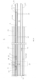
- FIG. 3 shows a longitudinal sectional view of a part of a steam generator 6, in particular a steam generator in a pressurized water reactor of a nuclear power plant.
- a steam generator 6 acts as a material barrier and heat exchanger between a primary reactor cooling circuit and a secondary reactor cooling circuit, thereby transferring heat from a pressurized primary reactor coolant to a secondary reactor coolant, vaporizing the secondary reactor coolant.
- the stabilizer 2 according to the invention is suited for other heat exchangers with a similar structure as well.
- the image section shows a plurality of so-called heating tubes or steam generator tubes 4 which during operation are flown through, usually in parallel flow configuration, by a fluid heating medium.
- this is a primary reactor coolant.
- the steam generator tubes 4 are led through and fixed in a pressure-sealed manner in a tube-sheet 34.
- the tube sheet 34 is part of a sealed enclosure, also known as a steam vessel, which during operation is flown through by a cooling medium.
- this is a secondary reactor coolant. Due to the thermal contact of the steam generator tubes 4 reaching into the steam space 36 of the steam vessel, heat is transferred from the heating medium to the cooling medium, thereby heating and usually vaporizing the cooling medium within the steam vessel.
- the primary reactor coolant (coming from a header not shown here) enters the steam generator tubes 4 from the left and flows to the right, firstly through the section within the tube sheet 34, and then through the steam space 36 of the steam vessel right to the tube sheet 34.
- this orientation is only exemplary for the purpose of description.
- the steam generator tubes 4 leave the steam vessel through another tube sheet not shown here or (after a bend) through another section of the same tube sheet 34, only a portion of which is shown here.
- the left-hand side of the tube sheet 34 may be called primary side, and the right-hand side may be called secondary side of the steam generator 6.
- the steam generator tubes 4 are straight, arranged parallel to each other, and have a constant inner diameter.
- Such a sealing plug 40 is shown in FIG. 3 in its operating position within a steam generator tube 4. More specifically, the sealing plug 40 is inserted from the primary side of the steam generator 6 into the according inlet opening 42 of the steam generator tube 4 in question, such that the sealing plug 40 is located within an entry region of the steam generator tube 4 within the tube sheet 34. Strong holding forces and a high level of leak tightness are achieved by fixing the sealing plug within the steam generator tube 4 by the process of roll expansion.
- a such-closed steam generator tube 4 might still rupture / tear off above the tube sheet 34 and waggle around, thereby causing damage to the surrounding steam generator tubes 4.
- a stabilizer 2 of the above-described kind is inserted into the damaged steam generator tube 4 as shown in FIG. 3 .
- the stabilizer 2 In its operation position the stabilizer 2 is located downstream of the sealing plug 40 within the steam generator tube 4 in question, as viewed in the normal flow direction 44 of the primary reactor coolant. More specifically, the stabilizer 2 is dimensioned and located such that its rear-end section III with the clamping section 30 and parts of or all of the middle section II with the supporting section 28 are located within the tube sheet 34 region (at least the supporting section 28 is arranged within the tube sheet 34), whereas the front-end section I with the supporting section 26 is located within the steam space 36 region of the steam generator tube 4. Hence, in the case of rupture in the most critical region slightly above the tube sheet 34, the disrupted steam generator tube 4 is hold and fixed in its initial position by the inserted stabilizer 2.
- the stabilizer 2 may also provide support for the steam generator tube 4 and may dampen tube oscillations even before rupture, thereby preventing or at least delaying rupture.
- Fixing of the stabilizer 2 within the steam generator tube is mainly achieved by the clamping section 30 of the rear-end section III.
- the supporting sections 26, 28 are intended mainly for supporting the surrounding steam generator tube 4 but do not need to provide fixing forces.
- the ring-like wall 28 of the rear-end section III is pressed radially outwards (i.e. clamped) against the tube wall of the steam generator tube 4 during the installation process, preferably by the process of roll expanding (similar to the fixing of the sealing plug 14 within the tube).
- a friction-locked connection of the stabilizer 2 to the steam generator tube 4 is established due to the permanent deformation of the ring-like wall 28 of the rear-end section III in radial direction.
- a well-defined fixing force can be achieved by controlling the torque of a tube expander tool used for the process of roll expansion, such that a given maximum clamping torque is reached but not exceeded.
- the clamping section 30 of the stabilizer 2 in the rear-end section III must be designed for relatively small forces only, minimizing mechanical stresses on the steam generator tube 4 and the surrounding tube sheet 34.
- the holding forces established during roll expansion can be set considerably lower than the holding forces related to the sealing plug 40. This also eases the removal of the stabilizer 2 from the steam generator tube 4 without damaging it in the case of need. Therefore, the installation process is reversible.
- the stabilizer 2 is pushed into to the steam generator tube 4 in question until the desired mounting position is reached, leaving some space in the primary-side entry region of the steam generator 4 tube for the sealing plug 40. Then the stabilizer 2 is fixed within the steam generator tube 4 by roll expansion in the clamping section 30 as described above. Afterwards, the sealing plug 14 is inserted into the steam generator tube 4 upstream to the stabilizer 2. Finally, the sealing plug 40 is fixed and sealed by roll expansion.
- the same set of remotely operatable tools can be used both for the installation of the stabilizer 2 and the sealing plug 40.
- existing tools for installing the sealing plug 40 can also be used for installing the stabilizer 2 without or with just small modifications. The whole installation process can be realized in a fast and efficient manner.
- Typical dimensions of the stabilizer 2 and the surrounding elements may be chosen as follows:
- the stabilizer according to the invention can be used in practically any steam generator, or more generally any heat exchanger, which comprises steam generator tubes, or more generally heating or cooling tubes to be flown through by a primary flow medium and which are fixed within a tube sheet.
- the term 'steam space' may be replaced by 'secondary flow medium space' or similar
- the term 'steam generator tube' may be replaced by 'heating or cooling tube' or 'heat exchanger tube' or 'primary flow medium tube' or similar.
Landscapes
- Engineering & Computer Science (AREA)
- Physics & Mathematics (AREA)
- High Energy & Nuclear Physics (AREA)
- Thermal Sciences (AREA)
- Mechanical Engineering (AREA)
- General Engineering & Computer Science (AREA)
- Life Sciences & Earth Sciences (AREA)
- Sustainable Development (AREA)
- Sustainable Energy (AREA)
- Heat-Exchange Devices With Radiators And Conduit Assemblies (AREA)
- Monitoring And Testing Of Nuclear Reactors (AREA)
Claims (13)
- Wärmetauscher mit einer Anzahl von Heiz- oder Kühlrohren (50), die jeweils in einem Rohrboden (34) befestigt sind und über den Rohrboden (34) hinausragen, wobei mindestens eines der Heiz- oder Kühlrohre (50) durch einen eingesetzten Stabilisator (2) stabilisiert ist, wobei das Heiz- oder Kühlrohr (50) einen ersten Rohrabschnitt aufweist, der innerhalb des Rohrbodens (34) befestigt ist, und einen zweiten Rohrabschnitt, der über den Rohrboden (34) hinausragt, wobei der Stabilisator (2) einen länglichen Körper (8) mit einem Klemmabschnitt (30) aufweist, der innerhalb des ersten Rohrabschnitts befestigt ist, und einen Stützabschnitt (26), der an dem zweiten Rohrabschnitt anliegt,wobei der Stabilisator (2) so konstruiert ist, dass ein Fluid durch und/oder um seinen Körper (8) strömen kann,wobei der Stabilisator (2) einen hinteren Abschnitt (III), einen vorderen Abschnitt (I) und einen mittleren Abschnitt (II) dazwischen umfasst, wobei der Klemmabschnitt (30) innerhalb des hinteren Abschnitts (III) angeordnet ist und der Stützabschnitt (26) innerhalb des vorderen Abschnitts (I) angeordnet ist;wobei der hintere Abschnitt (III) einen zentralen Hohlraum (16) aufweist, der durch eine hintere Öffnung (18) zugänglich ist, und wobei der Hohlraum (16) von einer ringförmigen Wand (20) umschlossen ist,dadurch gekennzeichnet, dass eine radiale Bohrung (24) durch die Wand (20) vom Hohlraum (16) bis zu einem kreisförmigen Spalt zwischen dem Körper (8) und dem Heiz- oder Kühlrohr (50) reicht und einen Fluid-Bypass bildet.
- Wärmetauscher nach Anspruch 1, wobei der Wärmetauscher ein Dampferzeuger für einen Druckwasserreaktor ist.
- Wärmetauscher nach Anspruch 2, mit einem an den Rohrboden (34) angrenzenden Dampfraum (36), undwobei es sich bei den Kühl- oder Heizrohren um Dampferzeugerrohre (4) handelt, die so ausgelegt sind, dass sie im Normalbetrieb ein primäres Reaktorkühlmittel führen, wobei jedes Dampferzeugerrohr (4) einen ersten Rohrabschnitt aufweist, der im Rohrboden (34) befestigt ist, und einen zweiten Rohrabschnitt, der in den Dampfraum (36) hineinragt,wobei mindestens eines der Dampferzeugerrohre (4) durch einen in den ersten Rohrabschnitt eingesetzten Verschlussstopfen (40) verschlossen ist, wobei der Stabilisator (2) ein separater Stabilisator (2) ist, der in das geschlossene Dampferzeugerrohr (4) neben oder über dem Verschlussstopfen (40) eingesetzt ist.
- Wärmetauscher nach Anspruch 3, wobei der Körper (8) eine im Wesentlichen zylindrische Form aufweist.
- Wärmetauscher nach Anspruch 3 oder 4, wobei der Stabilisator (2) einen weiteren Stützabschnitt (28) aufweist, der innerhalb des Mittelabschnitts (II) angeordnet ist.
- Wärmetauscher nach Anspruch 5, wobei der weitere Stützabschnitt (28) innerhalb des ersten Rohrabschnitts angeordnet ist.
- Wärmetauscher nach einem der Ansprüche 3 bis 6, wobei der Klemmabschnitt (30) und der/die Stützabschnitt(e) (26, 28) einen größeren Außendurchmesser als der Rest des Körpers (8) aufweisen.
- Wärmetauscher nach Anspruch 7, wobei der Stabilisator (2) am Dampferzeugerrohr (4) durch Walzexpansion eines Abschnitts der Wand (20) um den Hohlraum (16) befestigt ist.
- Wärmetauscher nach einem der Ansprüche 3 bis 8, wobei der Stabilisator (2) einstückig ausgebildet ist.
- Wärmetauscher nach Anspruch 9, wobei der Stabilisator (2) aus einer Legierung hergestellt ist.
- Wärmetauscher nach einem der Ansprüche 3 bis 10, wobei der Verschlussstopfen (40) in Strömungsrichtung des Primärreaktorkühlmittels gesehen vor dem Stabilisator (2) angeordnet ist.
- Verfahren zur Stabilisierung eines Heiz- oder Kühlrohres (50) eines Wärmetauschers, wobei das Heiz- oder Kühlrohr (50) einen ersten, in einem Rohrboden (34) befestigten Rohrabschnitt und einen zweiten, über den Rohrboden (34) hinausragenden Rohrabschnitt aufweist, wobei ein Stabilisator (2) in das Heiz- oder Kühlrohr (50) eingesetzt und eingeklemmt wird, wobei der Stabilisator (2) einen langgestreckten Körper (8) mit einem im ersten Rohrabschnitt befestigten Klemmabschnitt (30) und einem am zweiten Rohrabschnitt anliegenden Stützabschnitt (26) aufweist,wobei der Stabilisator (2) so konstruiert ist, dass ein Fluid durch und/oder um seinen Körper (8) strömen kann,wobei der Stabilisator (2) einen hinteren Abschnitt (III), einen vorderen Abschnitt (I) und einen mittleren Abschnitt (II) dazwischen umfasst, wobei der Klemmabschnitt (30) innerhalb des hinteren Abschnitts (III) angeordnet ist und der Stützabschnitt (26) innerhalb des vorderen Abschnitts (I) angeordnet ist;wobei der hintere Abschnitt (III) einen zentralen Hohlraum (16) aufweist, der durch eine hintere Öffnung (18) zugänglich ist, und wobei der Hohlraum (16) von einer ringförmigen Wand (20) umschlossen ist, undwobei eine radiale Bohrung (24) durch die Wand (20) vom Hohlraum (16) bis zu einem kreisförmigen Spalt zwischen dem Körper (8) und dem Heiz- oder Kühlrohr (50) reicht und einen Fluid-Bypass bildet;und wobei anschließend das Heiz- oder Kühlrohr (50) durch einen separaten Verschlussstopfen (40) verschlossen und abgedichtet wird.
- Verfahren nach Anspruch 12, wobei der Wärmetauscher ein Dampferzeuger ist.
Priority Applications (1)
| Application Number | Priority Date | Filing Date | Title |
|---|---|---|---|
| SI201930817T SI3963258T1 (sl) | 2019-04-30 | 2019-04-30 | Prenosnik toplote s stabilizatorjem |
Applications Claiming Priority (1)
| Application Number | Priority Date | Filing Date | Title |
|---|---|---|---|
| PCT/EP2019/061101 WO2020221444A1 (en) | 2019-04-30 | 2019-04-30 | Stabilizer for a heat exchanger tube |
Publications (2)
| Publication Number | Publication Date |
|---|---|
| EP3963258A1 EP3963258A1 (de) | 2022-03-09 |
| EP3963258B1 true EP3963258B1 (de) | 2024-07-24 |
Family
ID=66448527
Family Applications (1)
| Application Number | Title | Priority Date | Filing Date |
|---|---|---|---|
| EP19722832.3A Active EP3963258B1 (de) | 2019-04-30 | 2019-04-30 | Wärmetauscher mit einem stabilistor |
Country Status (7)
| Country | Link |
|---|---|
| EP (1) | EP3963258B1 (de) |
| JP (1) | JP7198374B2 (de) |
| AR (1) | AR118738A1 (de) |
| ES (1) | ES2991451T3 (de) |
| FI (1) | FI3963258T3 (de) |
| SI (1) | SI3963258T1 (de) |
| WO (1) | WO2020221444A1 (de) |
Family Cites Families (12)
| Publication number | Priority date | Publication date | Assignee | Title |
|---|---|---|---|---|
| FR2426232A1 (fr) * | 1978-05-17 | 1979-12-14 | Commissariat Energie Atomique | Dispositif pour colmater une fuite dans une portion droite d'un tube d'echangeur de chaleur |
| EP0047410B1 (de) * | 1980-09-09 | 1985-12-04 | Westinghouse Electric Corporation | Verfahren zum Hartlöten von Muffen |
| US4590991A (en) * | 1984-01-09 | 1986-05-27 | Westinghouse Electric Corp. | Flexible stabilizer for degraded heat exchanger tubing |
| FR2595439B1 (fr) * | 1986-03-10 | 1988-08-26 | Thome Paul | Methode de manchonnage de tubes de generateurs de vapeur et outils correspondants |
| US4800637A (en) | 1987-12-07 | 1989-01-31 | Combustion Engineering, Inc. | Method of removing plugs |
| DE3817654A1 (de) * | 1988-05-25 | 1989-11-30 | Abb Reaktor Gmbh | Einrichtung zum stabilisieren eines rohres eines waermetauschers |
| US5167064A (en) * | 1990-09-20 | 1992-12-01 | Expando Seal Tools, Inc. | Tube stabilizer assembly |
| WO1997021956A2 (en) | 1995-12-15 | 1997-06-19 | Westinghouse Electric Corporation | System and method for stabilizing a heat exchanger tube |
| JP2004138115A (ja) | 2002-10-16 | 2004-05-13 | Mitsubishi Heavy Ind Ltd | 配管損傷防止装置 |
| US20150219332A1 (en) | 2012-08-24 | 2015-08-06 | Mitsubishi Heavy Industries, Ltd. | Heat exchanger tube vibration suppression device and steam generator |
| CN102956276B (zh) | 2012-11-08 | 2015-06-03 | 中国核动力研究设计院 | 一种反应堆堆芯水位测量的流场稳定装置 |
| DE102016122513B3 (de) | 2016-11-22 | 2017-03-16 | Areva Gmbh | Verfahren zum Demontieren eines Dampferzeugers oder Wärmetauschers, insbesondere eines Dampferzeugers oder Wärmetauschers eines Kernkraftwerks |
-
2019
- 2019-04-30 EP EP19722832.3A patent/EP3963258B1/de active Active
- 2019-04-30 ES ES19722832T patent/ES2991451T3/es active Active
- 2019-04-30 WO PCT/EP2019/061101 patent/WO2020221444A1/en not_active Ceased
- 2019-04-30 JP JP2021564748A patent/JP7198374B2/ja active Active
- 2019-04-30 SI SI201930817T patent/SI3963258T1/sl unknown
- 2019-04-30 FI FIEP19722832.3T patent/FI3963258T3/fi active
-
2020
- 2020-04-20 AR ARP200101111A patent/AR118738A1/es unknown
Also Published As
| Publication number | Publication date |
|---|---|
| JP7198374B2 (ja) | 2022-12-28 |
| WO2020221444A1 (en) | 2020-11-05 |
| FI3963258T3 (fi) | 2024-10-04 |
| JP2022530553A (ja) | 2022-06-29 |
| EP3963258A1 (de) | 2022-03-09 |
| BR112021019286A2 (pt) | 2022-02-01 |
| SI3963258T1 (sl) | 2024-10-30 |
| AR118738A1 (es) | 2021-10-27 |
| ES2991451T3 (es) | 2024-12-03 |
Similar Documents
| Publication | Publication Date | Title |
|---|---|---|
| KR101981148B1 (ko) | 증기 발생기 가열관 수리 수단 및 수리 방법 | |
| JP4520017B2 (ja) | 原子炉熱スリーブの補修交換用連結装置及び交換方法 | |
| EP3246609B1 (de) | Ummanteltes rohr | |
| US8555647B2 (en) | Methods and apparatus for providing a sacrificial shield for a fuel injector | |
| US12523435B2 (en) | Device and method for restoring the tube-to-tube sheet weld joints in a shell-and-tube equipment | |
| US9709346B2 (en) | Centrally threaded plug for heat exchanger tube and removal tool | |
| US8640337B2 (en) | Pipe expansion method | |
| EP2577208B1 (de) | Rauchgas-luft-vorwärmofen und verfahren für den einbau sowie eine luftrohrkomponente für einen rauchgas-luft-vorwärmofen | |
| US8573288B2 (en) | Heat transfer tube support structure | |
| EP3963258B1 (de) | Wärmetauscher mit einem stabilistor | |
| EP0429267B1 (de) | Stopfen und Stopfverfahren für Rohrkörper | |
| EP1965132A1 (de) | Enthitzer | |
| US4783890A (en) | Method of repairing a steam generator tube by means of lining | |
| CN214305687U (zh) | 一种形状记忆合金管路连接组件 | |
| US9664067B2 (en) | Seal retaining assembly | |
| US5167907A (en) | Process for plugging a tube of a straight-tube heat exchanger | |
| KR20090026143A (ko) | 관 형상의 열 교환기용 스레디드 채널 폐쇄부 | |
| BR112021019286B1 (pt) | Gerador de vapor, trocador de calor e método para estabilizar um tubo de aquecimento ou resfriamento de um trocador de calor | |
| JPH0419442B2 (de) | ||
| EP4501527B1 (de) | Verfahren zur herstellung eines warmwasserspeichers | |
| CA3191377C (en) | Device and method for restoring the tube-to-tube sheet weld joints in a shell-and-tube equipment | |
| US12504240B2 (en) | Heat exchanger with expansion joint insert for thermal expansion and external force tolerance | |
| US20250334356A1 (en) | Heat exchanger with expansion joint for thermal expansion and external force tolerance | |
| JP7319139B2 (ja) | 配管構造体及び熱交換器 | |
| JP2009030813A (ja) | 熱交換器およびその補修方法 |
Legal Events
| Date | Code | Title | Description |
|---|---|---|---|
| STAA | Information on the status of an ep patent application or granted ep patent |
Free format text: STATUS: UNKNOWN |
|
| STAA | Information on the status of an ep patent application or granted ep patent |
Free format text: STATUS: THE INTERNATIONAL PUBLICATION HAS BEEN MADE |
|
| PUAI | Public reference made under article 153(3) epc to a published international application that has entered the european phase |
Free format text: ORIGINAL CODE: 0009012 |
|
| STAA | Information on the status of an ep patent application or granted ep patent |
Free format text: STATUS: REQUEST FOR EXAMINATION WAS MADE |
|
| 17P | Request for examination filed |
Effective date: 20211123 |
|
| AK | Designated contracting states |
Kind code of ref document: A1 Designated state(s): AL AT BE BG CH CY CZ DE DK EE ES FI FR GB GR HR HU IE IS IT LI LT LU LV MC MK MT NL NO PL PT RO RS SE SI SK SM TR |
|
| DAV | Request for validation of the european patent (deleted) | ||
| DAX | Request for extension of the european patent (deleted) | ||
| STAA | Information on the status of an ep patent application or granted ep patent |
Free format text: STATUS: EXAMINATION IS IN PROGRESS |
|
| P01 | Opt-out of the competence of the unified patent court (upc) registered |
Effective date: 20230419 |
|
| 17Q | First examination report despatched |
Effective date: 20230525 |
|
| RIC1 | Information provided on ipc code assigned before grant |
Ipc: F28F 11/02 20060101ALI20240213BHEP Ipc: F22B 37/00 20060101ALI20240213BHEP Ipc: F22B 1/16 20060101AFI20240213BHEP |
|
| GRAP | Despatch of communication of intention to grant a patent |
Free format text: ORIGINAL CODE: EPIDOSNIGR1 |
|
| STAA | Information on the status of an ep patent application or granted ep patent |
Free format text: STATUS: GRANT OF PATENT IS INTENDED |
|
| INTG | Intention to grant announced |
Effective date: 20240402 |
|
| GRAS | Grant fee paid |
Free format text: ORIGINAL CODE: EPIDOSNIGR3 |
|
| GRAA | (expected) grant |
Free format text: ORIGINAL CODE: 0009210 |
|
| STAA | Information on the status of an ep patent application or granted ep patent |
Free format text: STATUS: THE PATENT HAS BEEN GRANTED |
|
| AK | Designated contracting states |
Kind code of ref document: B1 Designated state(s): AL AT BE BG CH CY CZ DE DK EE ES FI FR GB GR HR HU IE IS IT LI LT LU LV MC MK MT NL NO PL PT RO RS SE SI SK SM TR |
|
| REG | Reference to a national code |
Ref country code: GB Ref legal event code: FG4D |
|
| REG | Reference to a national code |
Ref country code: CH Ref legal event code: EP |
|
| REG | Reference to a national code |
Ref country code: IE Ref legal event code: FG4D Ref country code: DE Ref legal event code: R096 Ref document number: 602019055680 Country of ref document: DE |
|
| REG | Reference to a national code |
Ref country code: NL Ref legal event code: FP |
|
| REG | Reference to a national code |
Ref country code: FI Ref legal event code: FGE |
|
| REG | Reference to a national code |
Ref country code: LT Ref legal event code: MG9D |
|
| REG | Reference to a national code |
Ref country code: ES Ref legal event code: FG2A Ref document number: 2991451 Country of ref document: ES Kind code of ref document: T3 Effective date: 20241203 |
|
| PG25 | Lapsed in a contracting state [announced via postgrant information from national office to epo] |
Ref country code: PT Free format text: LAPSE BECAUSE OF FAILURE TO SUBMIT A TRANSLATION OF THE DESCRIPTION OR TO PAY THE FEE WITHIN THE PRESCRIBED TIME-LIMIT Effective date: 20241125 |
|
| REG | Reference to a national code |
Ref country code: AT Ref legal event code: MK05 Ref document number: 1706594 Country of ref document: AT Kind code of ref document: T Effective date: 20240724 |
|
| PG25 | Lapsed in a contracting state [announced via postgrant information from national office to epo] |
Ref country code: PT Free format text: LAPSE BECAUSE OF FAILURE TO SUBMIT A TRANSLATION OF THE DESCRIPTION OR TO PAY THE FEE WITHIN THE PRESCRIBED TIME-LIMIT Effective date: 20241125 |
|
| PG25 | Lapsed in a contracting state [announced via postgrant information from national office to epo] |
Ref country code: NO Free format text: LAPSE BECAUSE OF FAILURE TO SUBMIT A TRANSLATION OF THE DESCRIPTION OR TO PAY THE FEE WITHIN THE PRESCRIBED TIME-LIMIT Effective date: 20241024 |
|
| PG25 | Lapsed in a contracting state [announced via postgrant information from national office to epo] |
Ref country code: GR Free format text: LAPSE BECAUSE OF FAILURE TO SUBMIT A TRANSLATION OF THE DESCRIPTION OR TO PAY THE FEE WITHIN THE PRESCRIBED TIME-LIMIT Effective date: 20241025 Ref country code: PL Free format text: LAPSE BECAUSE OF FAILURE TO SUBMIT A TRANSLATION OF THE DESCRIPTION OR TO PAY THE FEE WITHIN THE PRESCRIBED TIME-LIMIT Effective date: 20240724 |
|
| PG25 | Lapsed in a contracting state [announced via postgrant information from national office to epo] |
Ref country code: BG Free format text: LAPSE BECAUSE OF FAILURE TO SUBMIT A TRANSLATION OF THE DESCRIPTION OR TO PAY THE FEE WITHIN THE PRESCRIBED TIME-LIMIT Effective date: 20240724 |
|
| PG25 | Lapsed in a contracting state [announced via postgrant information from national office to epo] |
Ref country code: LV Free format text: LAPSE BECAUSE OF FAILURE TO SUBMIT A TRANSLATION OF THE DESCRIPTION OR TO PAY THE FEE WITHIN THE PRESCRIBED TIME-LIMIT Effective date: 20240724 |
|
| PG25 | Lapsed in a contracting state [announced via postgrant information from national office to epo] |
Ref country code: IS Free format text: LAPSE BECAUSE OF FAILURE TO SUBMIT A TRANSLATION OF THE DESCRIPTION OR TO PAY THE FEE WITHIN THE PRESCRIBED TIME-LIMIT Effective date: 20241124 Ref country code: AT Free format text: LAPSE BECAUSE OF FAILURE TO SUBMIT A TRANSLATION OF THE DESCRIPTION OR TO PAY THE FEE WITHIN THE PRESCRIBED TIME-LIMIT Effective date: 20240724 |
|
| PG25 | Lapsed in a contracting state [announced via postgrant information from national office to epo] |
Ref country code: HR Free format text: LAPSE BECAUSE OF FAILURE TO SUBMIT A TRANSLATION OF THE DESCRIPTION OR TO PAY THE FEE WITHIN THE PRESCRIBED TIME-LIMIT Effective date: 20240724 |
|
| PG25 | Lapsed in a contracting state [announced via postgrant information from national office to epo] |
Ref country code: RS Free format text: LAPSE BECAUSE OF FAILURE TO SUBMIT A TRANSLATION OF THE DESCRIPTION OR TO PAY THE FEE WITHIN THE PRESCRIBED TIME-LIMIT Effective date: 20241024 |
|
| PG25 | Lapsed in a contracting state [announced via postgrant information from national office to epo] |
Ref country code: RS Free format text: LAPSE BECAUSE OF FAILURE TO SUBMIT A TRANSLATION OF THE DESCRIPTION OR TO PAY THE FEE WITHIN THE PRESCRIBED TIME-LIMIT Effective date: 20241024 Ref country code: PL Free format text: LAPSE BECAUSE OF FAILURE TO SUBMIT A TRANSLATION OF THE DESCRIPTION OR TO PAY THE FEE WITHIN THE PRESCRIBED TIME-LIMIT Effective date: 20240724 Ref country code: NO Free format text: LAPSE BECAUSE OF FAILURE TO SUBMIT A TRANSLATION OF THE DESCRIPTION OR TO PAY THE FEE WITHIN THE PRESCRIBED TIME-LIMIT Effective date: 20241024 Ref country code: LV Free format text: LAPSE BECAUSE OF FAILURE TO SUBMIT A TRANSLATION OF THE DESCRIPTION OR TO PAY THE FEE WITHIN THE PRESCRIBED TIME-LIMIT Effective date: 20240724 Ref country code: IS Free format text: LAPSE BECAUSE OF FAILURE TO SUBMIT A TRANSLATION OF THE DESCRIPTION OR TO PAY THE FEE WITHIN THE PRESCRIBED TIME-LIMIT Effective date: 20241124 Ref country code: HR Free format text: LAPSE BECAUSE OF FAILURE TO SUBMIT A TRANSLATION OF THE DESCRIPTION OR TO PAY THE FEE WITHIN THE PRESCRIBED TIME-LIMIT Effective date: 20240724 Ref country code: GR Free format text: LAPSE BECAUSE OF FAILURE TO SUBMIT A TRANSLATION OF THE DESCRIPTION OR TO PAY THE FEE WITHIN THE PRESCRIBED TIME-LIMIT Effective date: 20241025 Ref country code: BG Free format text: LAPSE BECAUSE OF FAILURE TO SUBMIT A TRANSLATION OF THE DESCRIPTION OR TO PAY THE FEE WITHIN THE PRESCRIBED TIME-LIMIT Effective date: 20240724 Ref country code: AT Free format text: LAPSE BECAUSE OF FAILURE TO SUBMIT A TRANSLATION OF THE DESCRIPTION OR TO PAY THE FEE WITHIN THE PRESCRIBED TIME-LIMIT Effective date: 20240724 |
|
| PG25 | Lapsed in a contracting state [announced via postgrant information from national office to epo] |
Ref country code: SM Free format text: LAPSE BECAUSE OF FAILURE TO SUBMIT A TRANSLATION OF THE DESCRIPTION OR TO PAY THE FEE WITHIN THE PRESCRIBED TIME-LIMIT Effective date: 20240724 Ref country code: DK Free format text: LAPSE BECAUSE OF FAILURE TO SUBMIT A TRANSLATION OF THE DESCRIPTION OR TO PAY THE FEE WITHIN THE PRESCRIBED TIME-LIMIT Effective date: 20240724 Ref country code: RO Free format text: LAPSE BECAUSE OF FAILURE TO SUBMIT A TRANSLATION OF THE DESCRIPTION OR TO PAY THE FEE WITHIN THE PRESCRIBED TIME-LIMIT Effective date: 20240724 |
|
| PG25 | Lapsed in a contracting state [announced via postgrant information from national office to epo] |
Ref country code: EE Free format text: LAPSE BECAUSE OF FAILURE TO SUBMIT A TRANSLATION OF THE DESCRIPTION OR TO PAY THE FEE WITHIN THE PRESCRIBED TIME-LIMIT Effective date: 20240724 |
|
| PGFP | Annual fee paid to national office [announced via postgrant information from national office to epo] |
Ref country code: SI Payment date: 20250321 Year of fee payment: 7 |
|
| PG25 | Lapsed in a contracting state [announced via postgrant information from national office to epo] |
Ref country code: CZ Free format text: LAPSE BECAUSE OF FAILURE TO SUBMIT A TRANSLATION OF THE DESCRIPTION OR TO PAY THE FEE WITHIN THE PRESCRIBED TIME-LIMIT Effective date: 20240724 |
|
| REG | Reference to a national code |
Ref country code: DE Ref legal event code: R097 Ref document number: 602019055680 Country of ref document: DE |
|
| PG25 | Lapsed in a contracting state [announced via postgrant information from national office to epo] |
Ref country code: IT Free format text: LAPSE BECAUSE OF FAILURE TO SUBMIT A TRANSLATION OF THE DESCRIPTION OR TO PAY THE FEE WITHIN THE PRESCRIBED TIME-LIMIT Effective date: 20240724 Ref country code: SK Free format text: LAPSE BECAUSE OF FAILURE TO SUBMIT A TRANSLATION OF THE DESCRIPTION OR TO PAY THE FEE WITHIN THE PRESCRIBED TIME-LIMIT Effective date: 20240724 |
|
| PLBE | No opposition filed within time limit |
Free format text: ORIGINAL CODE: 0009261 |
|
| STAA | Information on the status of an ep patent application or granted ep patent |
Free format text: STATUS: NO OPPOSITION FILED WITHIN TIME LIMIT |
|
| 26N | No opposition filed |
Effective date: 20250425 |
|
| PGFP | Annual fee paid to national office [announced via postgrant information from national office to epo] |
Ref country code: GB Payment date: 20250417 Year of fee payment: 7 Ref country code: ES Payment date: 20250512 Year of fee payment: 7 |
|
| PGFP | Annual fee paid to national office [announced via postgrant information from national office to epo] |
Ref country code: BE Payment date: 20250423 Year of fee payment: 7 |
|
| PGFP | Annual fee paid to national office [announced via postgrant information from national office to epo] |
Ref country code: FR Payment date: 20250429 Year of fee payment: 7 |
|
| PGFP | Annual fee paid to national office [announced via postgrant information from national office to epo] |
Ref country code: CH Payment date: 20250501 Year of fee payment: 7 |
|
| PG25 | Lapsed in a contracting state [announced via postgrant information from national office to epo] |
Ref country code: SE Free format text: LAPSE BECAUSE OF FAILURE TO SUBMIT A TRANSLATION OF THE DESCRIPTION OR TO PAY THE FEE WITHIN THE PRESCRIBED TIME-LIMIT Effective date: 20240724 |
|
| REG | Reference to a national code |
Ref country code: DE Ref legal event code: R119 Ref document number: 602019055680 Country of ref document: DE |
|
| PG25 | Lapsed in a contracting state [announced via postgrant information from national office to epo] |
Ref country code: LU Free format text: LAPSE BECAUSE OF NON-PAYMENT OF DUE FEES Effective date: 20250430 |
|
| PG25 | Lapsed in a contracting state [announced via postgrant information from national office to epo] |
Ref country code: MC Free format text: LAPSE BECAUSE OF FAILURE TO SUBMIT A TRANSLATION OF THE DESCRIPTION OR TO PAY THE FEE WITHIN THE PRESCRIBED TIME-LIMIT Effective date: 20240724 |
|
| REG | Reference to a national code |
Ref country code: CH Ref legal event code: R18 Free format text: ST27 STATUS EVENT CODE: U-0-0-R10-R18 (AS PROVIDED BY THE NATIONAL OFFICE) Effective date: 20260106 |
|
| PG25 | Lapsed in a contracting state [announced via postgrant information from national office to epo] |
Ref country code: DE Free format text: LAPSE BECAUSE OF NON-PAYMENT OF DUE FEES Effective date: 20251104 |
|
| PG25 | Lapsed in a contracting state [announced via postgrant information from national office to epo] |
Ref country code: IE Free format text: LAPSE BECAUSE OF NON-PAYMENT OF DUE FEES Effective date: 20250430 |
|
| PGFP | Annual fee paid to national office [announced via postgrant information from national office to epo] |
Ref country code: FI Payment date: 20260324 Year of fee payment: 8 |
|
| PGFP | Annual fee paid to national office [announced via postgrant information from national office to epo] |
Ref country code: NL Payment date: 20260326 Year of fee payment: 8 |