EP3963211B1 - Schmiermittelzufuhrsystem und vakuumpumpe - Google Patents
Schmiermittelzufuhrsystem und vakuumpumpe Download PDFInfo
- Publication number
- EP3963211B1 EP3963211B1 EP20723503.7A EP20723503A EP3963211B1 EP 3963211 B1 EP3963211 B1 EP 3963211B1 EP 20723503 A EP20723503 A EP 20723503A EP 3963211 B1 EP3963211 B1 EP 3963211B1
- Authority
- EP
- European Patent Office
- Prior art keywords
- lubricant
- collar
- container body
- supply system
- housing
- Prior art date
- Legal status (The legal status is an assumption and is not a legal conclusion. Google has not performed a legal analysis and makes no representation as to the accuracy of the status listed.)
- Active
Links
Images



Classifications
-
- F—MECHANICAL ENGINEERING; LIGHTING; HEATING; WEAPONS; BLASTING
- F04—POSITIVE - DISPLACEMENT MACHINES FOR LIQUIDS; PUMPS FOR LIQUIDS OR ELASTIC FLUIDS
- F04D—NON-POSITIVE-DISPLACEMENT PUMPS
- F04D19/00—Axial-flow pumps
- F04D19/02—Multi-stage pumps
- F04D19/04—Multi-stage pumps specially adapted to the production of a high vacuum, e.g. molecular pumps
- F04D19/042—Turbomolecular vacuum pumps
-
- F—MECHANICAL ENGINEERING; LIGHTING; HEATING; WEAPONS; BLASTING
- F04—POSITIVE - DISPLACEMENT MACHINES FOR LIQUIDS; PUMPS FOR LIQUIDS OR ELASTIC FLUIDS
- F04D—NON-POSITIVE-DISPLACEMENT PUMPS
- F04D29/00—Details, component parts, or accessories
- F04D29/05—Shafts or bearings, or assemblies thereof, specially adapted for elastic fluid pumps
- F04D29/056—Bearings
-
- F—MECHANICAL ENGINEERING; LIGHTING; HEATING; WEAPONS; BLASTING
- F04—POSITIVE - DISPLACEMENT MACHINES FOR LIQUIDS; PUMPS FOR LIQUIDS OR ELASTIC FLUIDS
- F04D—NON-POSITIVE-DISPLACEMENT PUMPS
- F04D29/00—Details, component parts, or accessories
- F04D29/05—Shafts or bearings, or assemblies thereof, specially adapted for elastic fluid pumps
- F04D29/056—Bearings
- F04D29/059—Roller bearings
-
- F—MECHANICAL ENGINEERING; LIGHTING; HEATING; WEAPONS; BLASTING
- F04—POSITIVE - DISPLACEMENT MACHINES FOR LIQUIDS; PUMPS FOR LIQUIDS OR ELASTIC FLUIDS
- F04D—NON-POSITIVE-DISPLACEMENT PUMPS
- F04D17/00—Radial-flow pumps, e.g. centrifugal pumps; Helico-centrifugal pumps
- F04D17/08—Centrifugal pumps
- F04D17/16—Centrifugal pumps for displacing without appreciable compression
- F04D17/168—Pumps specially adapted to produce a vacuum
-
- F—MECHANICAL ENGINEERING; LIGHTING; HEATING; WEAPONS; BLASTING
- F04—POSITIVE - DISPLACEMENT MACHINES FOR LIQUIDS; PUMPS FOR LIQUIDS OR ELASTIC FLUIDS
- F04D—NON-POSITIVE-DISPLACEMENT PUMPS
- F04D29/00—Details, component parts, or accessories
- F04D29/05—Shafts or bearings, or assemblies thereof, specially adapted for elastic fluid pumps
- F04D29/056—Bearings
- F04D29/058—Bearings magnetic; electromagnetic
-
- F—MECHANICAL ENGINEERING; LIGHTING; HEATING; WEAPONS; BLASTING
- F04—POSITIVE - DISPLACEMENT MACHINES FOR LIQUIDS; PUMPS FOR LIQUIDS OR ELASTIC FLUIDS
- F04D—NON-POSITIVE-DISPLACEMENT PUMPS
- F04D29/00—Details, component parts, or accessories
- F04D29/06—Lubrication
- F04D29/063—Lubrication specially adapted for elastic fluid pumps
-
- F—MECHANICAL ENGINEERING; LIGHTING; HEATING; WEAPONS; BLASTING
- F16—ENGINEERING ELEMENTS AND UNITS; GENERAL MEASURES FOR PRODUCING AND MAINTAINING EFFECTIVE FUNCTIONING OF MACHINES OR INSTALLATIONS; THERMAL INSULATION IN GENERAL
- F16C—SHAFTS; FLEXIBLE SHAFTS; ELEMENTS OR CRANKSHAFT MECHANISMS; ROTARY BODIES OTHER THAN GEARING ELEMENTS; BEARINGS
- F16C2360/00—Engines or pumps
- F16C2360/44—Centrifugal pumps
- F16C2360/45—Turbo-molecular pumps
Definitions
- the invention relates to lubricant supply systems for supplying lubricant to a rolling bearing of a vacuum pump. Further, the present invention relates to a vacuum pump with such a lubricant supply system. Further, the present invention relates to a method for fabrication of such a lubricant supply system
- Many pumps comprise an impeller in the form of a rotor mounted on a rotor shaft for rotation relative to a surrounding stator.
- the rotor shaft is supported by a bearing arrangement that may comprise two bearings located at or intermediate respective ends of the shaft.
- One or both of these bearings may be a rolling bearing.
- the upper bearing may be in the form of a magnetic bearing and the lower bearing is a rolling bearing.
- This arrangement may be used in vacuum pumps such as, for example, turbomolecular vacuum pumps.
- a typical rolling bearing comprises an inner race fixed relative to the rotor shaft, an outer race and a plurality of rolling elements located between the races for allowing relative rotation of the inner race and the outer race. To prevent mutual contact between the rolling elements they are often guided and evenly spaced by a cage. Adequate lubrication is essential to ensure accurate and reliable operation of rolling bearings.
- the main purpose of the lubricant is - to establish a load-carrying film separating the bearing components in rolling and sliding contact in order to minimize fiction and wear. Other purposes include the prevention of oxidation or corrosion of the bearing components, the formation of a barrier to contaminants and the transfer of heat away from the bearing components.
- the lubricant is generally in the form of either oil or grease.
- the oil reservoir from which the felt wick is supplied may comprise two stacks of layers of felt that lay against respective major surfaces of the felt wick so that the felt wick is sandwiched between the two stacks.
- the feed rate of oil to the bearing may be affected by a number of factors, including the taper angle of the conical nut, the rate of transfer of oil from the wick to the nut, the surface finish of the conical surface of the nut, temperature and the speed of rotation of the shaft.
- the position of the oil leaving the lubricant transfer device might vary and as a consequence the oil might not reach homogenously the respective bearing.
- US2017/102034 discloses a lubricant transfer device that passes through a hole in the lubricant reservoir and has a return path, in the form of a cylindrical tube member running from the outer race of the bearing to the reservoir.
- EP 2060794 discloses a lubricant reservoir comprising a delivery channel going from a reservoir to the one end of a surface of a lubricant transfer device and a return channel going from the bearing to the reservoir.
- US4286829 discloses a system for lubricating a bearing comprising a ring made of a porous material fixed adjacent at least one axial end of the stationary race of a bearing, an annular lubricant source located adjacent the porous ring which extends into the region of the running surface of the rotating race whereby the lubricant under the influence of negative pressure generated by high rotation is drawn from the lubricant reservoir through the porous ring, circulated through the bearing raceways and rolling elements and returned to the porous ring along the running surface of the stationary race ring.
- the lubricant supply system in particular for a vacuum pump in accordance to the present invention comprises a lubricant container body defining a lubricant reservoir.
- the lubricant reservoir containing a lubricant or oil to be fed to the bearing of a vacuum pump.
- the lubricant container body comprises an indentation or through-hole to receive a lubricant transfer device of the vacuum pump.
- the indentation or through-hole of the lubricant container body is at least partially surrounded by a collar extending from said lubricant container body.
- the collar has the advantage that excess oil or lubricant is collected which drops of or is centrifuged from the lubricant transfer device during operation. Without the collar in accordance with the known prior art, oil dripping off from the lubricant transfer device of the vacuum pump before the intended delivery point in the bearing might return to the lubricant container body, if the vacuum pump is in an upright position. However, if the vacuum pump is in an inverted position oil or lubricant centrifuged from the lubricant transfer device drips into the bearing of the vacuum pump, which might result in increased oil churning losses.
- the lubricant supply system comprises at least one lubricant return member extending from the lubricant container body to return the lubricant after the lubricant has passed through the rolling bearing of the vacuum pump. If the vacuum pump is in an upright position all lubricant provided to the rolling bearing of the vacuum pump might be dripping back by gravity towards the lubricant container body and then recycled in a lubricant circulation. However, if the vacuum pump is in an inverted position the lubricant provided to the rolling bearing of the vacuum pump by the transfer device is then returned by the lubricant return member to the reservoir.
- the collar extends less from the lubricant container body than any of the lubricant return member.
- the collar is completely surrounding the indentation or through-hole.
- excess oil dripping off from the lubricant transfer device of the vacuum pump in any direction can be collected by the additional collar.
- the porous material of the collar might be made of a stable fibrous material or materials that are able to conduct lubricant by a capillary or wicking action.
- the fibrous material may be natural or synthetic and, in some examples, may be a felt material.
- the felt is a woven or unwoven material and/or a material with chemically bonded fibers.
- the porous material absorbs the oil by capillary forces.
- the porosity must not be closed but interconnected between pores and open to the outside. The porous material thus stores the lubricant in the container body.
- the collar comprising a porous material in fluid communication with the lubricant container body.
- the porous material might be made of a stable fibrous material or materials that are able to conduct lubricant by a capillary or wicking action.
- the fibrous material may be natural or synthetic and, in some examples, may be a felt material.
- the at least one lubricant return member is also made of a porous material.
- the at least one lubricant return member is integrally formed with the lubricant container body.
- the lubricant supply system comprises more than one lubricant return member, wherein each lubricant return member is preferably formed as strip or finger extending from the lubricant container body beyond the position of the rolling bearing of the vacuum pump.
- the collar extends by more than 1mm and less 20mm from the lubricant container body.
- the collar extends from the lubricant container body by more than 1mm and less than 10mm and more preferably by more than 2mm and less than 6mm.
- the lubricant supply system comprises a contactor connected to the lubricant container body to engage the lubricant transfer device of the vacuum pump in order to transfer lubricant or oil from the reservoir to the lubricant transfer device.
- the contactor might be a wicking element wherein the wicking element is made of porous material such as felt or the like. Further, the contactor might be sandwiched between two elements of the lubricant container body to receive a lubricant or oil from the reservoir of the lubricant container body.
- the contactor is made of a porous material extending radially into the indentation or through-hole and more preferably being made integral with the lubricant container body.
- the lubricant container body has an approximately annular shape wherein the indentation or though-hole might be arranged centrically.
- the lubricant container body has a first major surface and an opposite second major surface wherein the collar is extending from the first major surface and the indentation is defined in the first major surface or the through-hole is extending from the first major surface to the second major surface.
- the lubricant container body might have a cylindrical shape.
- the collar is made of a flat element by rolling up this flat element.
- the collar is connected to a plurality of strip elements extending radially from the collar.
- the strips elements might be formed by partial incisions of the flat element before rolling up the flat element.
- the strip elements are connected to the first major surface to fluidly connect the collar with the lubricant container body.
- excess oil or lubricant collected by the collar is fed back thought the strip elements to the lubricant container body and is recirculated.
- the strip elements are inserted and sandwiched by one of the elements of the lubricant container body stack or sandwiched between the contactor and one of the elements of the lubricant container body stack.
- the lubricant supply system comprises a housing wherein the lubricant container body is at least partially and more preferably completely enclosed by the housing. Therein, the collar is extending from the housing.
- the collar is connected to the housing by at least one web.
- more than one web can be used to connect to the collar to the housing.
- the housing comprises at least one ring element surrounding and supporting the collar, wherein the ring element is connected to the housing by at least one web.
- the ring element is connected to the housing by at least one web.
- the lubricant supply system is formed as a cartridge which might be easy to implement to any existing vacuum pumps.
- an object of the present invention is to provide a vacuum pump according to claim 10.
- the vacuum pump might be a Siegbahn pump, a Gaede pump, a Holweck pump or, in general, a molecular-drag pump as well as a turbomolecular pump.
- the vacuum pump comprises a pump housing and a rotor shaft disposed in the pump housing having an axis of rotation. To the rotor shaft might be connected at least one pump element in order to convey a gaseous medium from an inlet of the vacuum pump to an outlet of the vacuum pump.
- the vacuum pump in accordance to the present invention comprises at least one rolling bearing for supporting the rotor shaft and allow fast rotation of the rotor shaft for pumping action.
- the vacuum pump comprises a lubricant supply system as previously described.
- at least one further bearing is built as magnetic bearing supporting the rotor shaft in a contact-free manner.
- the vacuum pump in accordance to the present invention comprises a lubricant transfer device mounted to the rotor shaft and extending into the indentation or through-hole of the lubricant supply system to receive lubricant from said lubricant supply system and to transfer the lubricant to the rolling ring.
- the collar is extending towards the rolling bearing.
- any lubricant or oil dripping off from the transfer device too early, such that it would not reach the rolling bearing, is collected by the collar and recirculated to the lubricant reservoir.
- the collar is not in contact with the rolling bearing and is also not in contact with the lubricant transfer device.
- a gap exists between 1 to 5mm and preferably between 1 to 2 mm.
- the at least one lubricant return member of the lubricant supply system extend beyond the rolling bearing in order to return lubricant or oil that has been passed through the rolling bearing for recirculation.
- the method comprises the steps of:
- the collar after inserting the collar into the housing and before inserting the lubricant container body into the housing, the collar might be fixed by a fixing element inserted into the housing from the same side as the collar. More preferably, the fixing element is interacting with a ring element of the housing to clampingly fix the collar into the housing.
- the lubricant supply system is built according to the features as described above.
- a turbomolecular pump 110 comprises a housing 112, a pumping mechanism 114 disposed in the housing, an inlet 116 and an outlet 118.
- the pumping mechanism 114 may comprise a turbomolecular pumping mechanism comprising a plurality of rotor blades 120 disposed in interleaving relationship with a plurality of stator discs 122.
- the rotor blades 120 may be mounted on, or integral with, a rotor shaft 124 that has a longitudinal axis (axis of rotation) 126.
- the rotor shaft 124 is driven to rotate about the axis of rotation 126 by a motor 128 in order to convey a gaseous medium from an inlet 116 to an outlet 118 of the pump.
- the pumping mechanism 114 may additionally comprise a molecular drag pumping mechanism 130, which may be a Gaede mechanism, a Holweck mechanism or a Siegbahn mechanism. There may be additional, or alternative, mechanisms downstream of the molecular drag pumping mechanism such as an aerodynamic pumping mechanism comprising a regenerative mechanism.
- the rotor shaft 124 is supported by a plurality of bearings 132, 134.
- the plurality of bearings may comprise two bearings 132, 134 positioned at, or adjacent, respective ends of the rotor shaft 124 as shown in Figure 1 , or alternatively, intermediate the ends.
- a rolling bearing 132 supports a first end portion of the rotor shaft 124 and a magnetic bearing 134 supports a second end portion of the rotor shaft 124.
- a second rolling bearing may be used as an alternative to the magnetic bearing 134.
- a back-up rolling bearing (not shown) may be provided.
- the rolling bearing 132 is disposed above the datum 135.
- the longitudinal axis 126 is disposed perpendicular to the datum 135 and the rolling bearing 132 is disposed towards the top of the turbomolecular pump 110 and the bearing 134 is towards the bottom of the pump.
- the turbomolecular pump 110 additionally comprises a lubrication system to lubricate the rolling bearing 132.
- the lubrication system may comprise a lubricant supply system 136 and a lubricant transfer device 138 provided on the rotor shaft 124 to transfer lubricant from the lubricant supply system to the rolling bearing 132.
- the rolling bearing 132 is provided between the first end portion of the rotor shaft 124 and a bearing housing 142 of the turbo-molecular pump 110.
- the bearing housing 142 may be integral with the housing 112 or a component fitted to the housing.
- the rolling bearing 132 comprises an inner race 144 fixed relative to the rotor shaft 124, an outer race 146 fixed relative to the bearing housing 142, a plurality of rolling elements 148 disposed between the inner and outer races and a cage 150 that is configured to provide a desired spacing between the rolling elements.
- the cage 150 is piloted on its outer diameter so that the cage pilot land 152 is disposed in face-to-face relation with the outer race 146.
- the cage pilot land 152 may comprise an annular surface, which in the orientation of the pump 110 shown in Figure 2 is disposed above the rolling elements 148.
- the rolling bearing 132 is configured to allow relative rotation of the inner and outer races 144, 146 so that it can support the rotor shaft 124 during rotation of the rotor shaft relative to the housing 112.
- the rolling bearing 132 is supplied with a lubricant from the lubricant supply system 136 to establish a load-carrying film that minimizes friction and wear in the bearing and provides support for the cage 150 by separating the rolling elements 148 from the inner and outer races 144, 146 and the cage and the cage pilot land 152 from the outer race.
- the lubricant is liquid and may be an oil.
- the lubricant supply system 136 may comprise a lubricant container body 154 built by two lubricant container body portions 154-1, 154-2 containing a lubricant reservoir, one or more fingers 156 projecting inwardly of the lubricant container body 154 to engage the lubricant transfer device 138 and one or more lubricant return members 158.
- lubricant from the lubricant reservoir flows to the lubricant transfer device 138 via the one or more fingers 156 and is transferred by the lubricant transfer device 138 to the rolling bearing as indicated by the arrows in Figure 2 .
- Lubricant that has passed through the rolling bearing 132 is returned to the lubricant reservoir via the one or more lubricant return members 158.
- the or each finger 156 and the or each lubricant return member 158 may be connected by an integral body member 160.
- an integral body member 160 For the sake of simplicity, in the description that follows, reference will be made to just one finger 156 and one lubricant return member 158, although, it is to be understood that this is not to be taken as limiting.
- the lubricant supply system 136 may further comprise a collection channel 168 that is configured to receive lubricant that has been supplied to the rolling bearing 132 via the lubricant transfer device 138 and then passed through the bearing.
- the collection channel 168 has a downstream end 170 and an upstream end.
- An upstream end 174 of the lubricant return member 158 may be disposed at or adjacent the downstream end 170 of the collection channel 168 to receive and return lubricant from the collection channel 168 to the lubricant container body 154.
- An absorbent collector body 176 may be disposed in the collection channel 168.
- the lubricant supply system 136 may comprise a deflector 140 mounted on the rotor shaft 124.
- the deflector 140 may comprise a drip former 180 ( Figure 2 ) to prevent the flow of lubricant along the underside of the deflector (as viewed in Figure 2 ) towards the rotor shaft 124.
- the drip former 180 comprises a depending annular skirt, although, it may take many other forms such as an annular groove in the underside of the deflector.
- the deflector 140 may be mounted on the rotor shaft 124 such that the rolling bearing 132 is disposed between the deflector and the lubricant transfer device 138.
- the positioning of the deflector 140 is such that lubricant that has passed through the rolling bearing 132 may impinge on the deflector.
- the deflector 140 is configured to deflect lubricant that has passed through the rolling bearing 132 into the collection channel 168.
- the deflector 140 may be seated on a shoulder 184 defined by a reduced diameter section of the rotor shaft 124.
- the shoulder 184 may be disposed adjacent a bore provided in a partition 188 that separates the pumping mechanism 114 and motor 128 from the rolling bearing 132.
- the partition 188 may be an integral part of the housing 112 or an element fitted into and secured to the housing 112.
- the deflector 140 is configured to shield the bore against the ingress of lubricant that has passed through the rolling bearing 132 and deflect, or divert, the lubricant into the collection channel 168.
- the deflector 140 is mounted on the rotor shaft 124.
- a deflector may be provided on rolling bearing, for example on the inner race.
- the lubricant supply system 136 may comprise a housing 10 to hold the lubricant container body 154, lubricant return member 158 and body member 160 in an assembled condition.
- the housing 10 may comprise a main housing body 11 configured to receive the container body portions 154-1, 154-2 and body member 160 and a return member holder body 13 that may be integral with the main housing body 11, secured to the main housing body or disposed in the turbomolecular vacuum pump 110 such that it abuts the inner end of the main housing body.
- the return member holder body 13 may be an elongate body defining a lengthways extending channel configured to receive and support the lubricant return member 158.
- the housing may comprise one or more plastics moldings or is made by a 3D-printing process.
- the housing 10 may be received in a recess 200 provided at an end of the housing 112.
- the inner end of the recess 200 may be at least in part defined by the partition 188.
- the rolling bearing 132 is housed in the recess 200.
- the housing 10 may be held in place in the recess 200 by an end cap 202 that may be secured to the housing 12 by bolts, clamps, screws or any other suitable securing mechanism.
- the lubricant transfer device 138 may comprise a hollow frusto-conical body secured to the rotor shaft 124.
- the lubricant transfer device 138 has a longitudinal axis that is coincident with the longitudinal axis 126 of the rotor shaft 124.
- the lubricant transfer device 138 has an outer surface 206 that tapers radially outwardly with respect to the longitudinal axis 126 as it approaches the rolling bearing 132.
- the rotor shaft 124 and lubricant transfer device 138 may be provided with male and female threads respectively to enable the lubricant transfer device to be screwed onto the rotor shaft in the manner of a nut.
- the lubricant transfer device 138 may comprise a sleeve-like construction that is slid onto the rotor shaft 124 and secured to the rotor shaft by means of a nut, holt, screw or other suitable securing means,
- the lubricant transfer device may be a solid body provided which a male thread at one end to screw into a female thread provided in an end of the rotor shaft.
- the lubricant collected in the collector body 176 migrates to the downstream end 170 of the collection channel 168 by a capillary or wicking action and passes into the lubricant return member 158 via which it is returned to the reservoir of the lubricant container body 154.
- lubricant supplied to the rolling bearing 132 can be effectively returned to the lubricant reservoir for recirculation.
- the collection channel 168 may be an annular channel, or passage that surrounds the rotor shaft such that the upstream end 172 of the collection channel is defined by the inner circumference of the annular channel and the downstream end 170 is defined by the outer circumference of the annular collection channel.
- an annular collector body 176 may be fitted in the collection channel 168, in which case the upstream end of the lubricant return member 158 may about the collector body at or adjacent the outer periphery of the collector body.
- the absorbent collector body 176 may be omitted, in which case the upstream end 174 of the lubricant return member 158 may be disposed in the collection channel 168 such that, in use, it is in direct contact with lubricant pooling in the collection channel 168.
- An additional collar 155 is connected to the lubricant container body 154 and surrounding the lubricant transfer device 138. Therein, the collar 155 is not in contact neither with the lubricant transfer device 138 nor with the rolling bearing 132.
- the collar 155 is also made from a porous material and is in fluid communication with the lubricant reservoir of the lubricant container body 154.
- the lubricant container body 154, collar 155, finger 156, lubricant return member 158, body member 160 and collector body 176 may be made of a stable fibrous material or materials that are able to conduct lubricant by a capillary or wicking action.
- the fibrous material may be natural or synthetic and, in some examples, may be a felt material.
- the lubricant container body 154, collar 155, finger 156, lubricant return member 158 and body member 160 may be made of the same fibrous material, although in some examples different fibrous materials may be used.
- one or both lubricant container body portions 154-1, 154-2 of the lubricant reservoir body may comprise a plurality of relatively thin layers of fibrous material stacked one upon another as shown in Figure 2 .
- FIG 4A shows a lubricant supply system in accordance to the present invention.
- the lubricant supply system is built as cartridge having an annular housing 10 containing the lubricant container body 154.
- the lubricant container body 154 comprises a through-hole 12, which is centrically arranged in order to receive the lubricant transfer device 138.
- the hole 12 is surrounded by the additional collar 155 that extends away from the housing 10 towards the rolling bearing 132, thereby surrounding the lubricant transfer device 138.
- the additional collar 155 is surrounded by a ring element 14, which is connected to the housing 10 by webs 16 providing sufficient stability to the additional collar 155.
- the lubricant supply system of figure 4A shows three lubricant return members 158 extending also from the housing 10 of the lubricant supply system. Therein, the lubricant return member 158 extends beyond the rolling bearing 132, while the additional collar 155 extends towards the rolling bearing 132 but ends before the rolling bearing as shown in Figures 2 and 3 .
- Figure 4A also shows strip elements 18 connected to the collar 155.
- the strip elements 18 are made from the material as the collar 155.
- the collar 155 is in fluid communication with the strip elements 18.
- Preferably collar 155 and the strip elements 18 are integrally formed or one piece. The excess oil or lubricant collected by the collar 155 is fed back to the lubricant reservoir of the lubricant container body 154 and recirculated.
- the collar and the strip elements are made from a single flat element 19, which is incised and provides a plurality of partial incisions 20 as well as an uncut part 22.
- the uncut part 22 will form the collar while the incised part forms the strip elements 18.
- the flat element 19 is rolled up in order to form the collar 155 integrally connected to the strip elements 18 as shown in Figure 5B by bending the cut parts ourside by about 90 degrees.
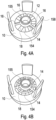
- FIG 4B showing another embodiment of the lubricant supply system having a cartridge formed by a housing 10.
- ring elements 14 are used in order to stabilize the collar 155 as well as attaching the strip elements 18 to the lubricant container body 154 in order to maintain fluid communication between the reservoir of the lubricant container body 154 and the collar 155 via the strip elements 18.
Landscapes
- Engineering & Computer Science (AREA)
- Mechanical Engineering (AREA)
- General Engineering & Computer Science (AREA)
- Non-Positive Displacement Air Blowers (AREA)
- Rolling Contact Bearings (AREA)
Claims (13)
- Schmiermittelzufuhrsystem zum Zuführen von Schmiermittel zu einem Wälzlager einer Vakuumpumpe, wobei das Schmiermittelzufuhrsystem umfasst:einen Schmiermittelbehälterkörper (154), der ein Schmiermittelreservoir definiert, wobei der Schmiermittelbehälterkörper eine Vertiefung oder ein Durchgangsloch (12) für die Aufnahme einer Schmiermittelübertragungsvorrichtung (138) einer Vakuumpumpe umfasst;wobei die Vertiefung oder das Durchgangsloch (12) mindestens teilweise von einem sich von dem Schmiermittelbehälterkörper erstreckenden Bund (155) umgeben ist, wobei der Bund dazu konfiguriert ist, zentrifugiertes oder von der Schmiermittelübertragungsvorrichtung tropfendes Schmiermittel zu sammeln; undmindestens ein Schmiermittelrücklaufelement (158), das sich vom Schmiermittelbehälterkörper erstreckt und dazu konfiguriert ist, Schmiermittel zurückzuführen; wobeisich der Bund (155) weniger vom Schmiermittelbehälterkörper erstreckt als das Schmiermittelrücklaufelement; dadurch gekennzeichnet, dass der Bund ein poröses Material in Fluidverbindung mit dem Schmiermittelbehälterkörper umfasst.
- Schmiermittelzufuhrsystem nach Anspruch 1, dadurch gekennzeichnet, dass der Bund die Vertiefung oder das Durchgangsloch vollständig umgibt.
- Schmiermittelzufuhrsystem nach Anspruch 1 oder 2, dadurch gekennzeichnet, dass der Schmiermittelbehälterkörper ein poröses Material umfasst.
- Schmiermittelzufuhrsystem nach einem der Ansprüche 1 bis 3, dadurch gekennzeichnet, dass sich der Bund um mehr als 1 mm und weniger als 20 mm, vorzugsweise mehr als 1 mm und weniger als 10 mm und am stärksten bevorzugt um mehr als 2 mm und weniger als 6 mm erstreckt.
- Schmiermittelzufuhrsystem nach einem der Ansprüche 1 bis 4, gekennzeichnet durch eine Schaltvorrichtung für das Herstellen eines Eingriffs mit einer Schmiermittelübertragungsvorrichtung zum Übertragen von Schmiermittel aus dem Behälter zu der Schmiermittelübertragungsvornchtung, wobei die Schaltvorrichtung optional aus porösem Material hergestellt ist, sich radial in die Vertiefung oder das Durchgangsloch erstreckend und vorzugsweise einstückig mit dem Schmiermittelbehälterkörper hergestellt.
- Schmiermittelzufuhrsystem nach einem der Ansprüche 1 bis 5, dadurch gekennzeichnet, dass der Schmiermittelbehälterkörper Folgendes aufweist: (i) eine Ringform, und die Vertiefung oder das Durchgangsloch ist vorzugsweise zentrisch angeordnet; und/oder (ii) eine erste Hauptfläche und eine gegenüberliegende zweite Hauptfläche, wobei sich der Bund von der ersten Hauptfläche erstreckt und die Vertiefung in der ersten Hauptfläche definiert ist oder sich das Durchgangsloch von der ersten Hauptfläche zur zweiten Hauptfläche erstreckt.
- Schmiermittelzufuhrsystem nach einem der Ansprüche 1 bis 6, dadurch gekennzeichnet, dass der Bund aus einem flachen Element, vorzugsweise durch Aufrollen, hergestellt ist.
- Schmiermittelzufuhrsystem nach einem der Ansprüche 1 bis 7, dadurch gekennzeichnet, dass der Bund mit einer Vielzahl von Streifenelementen verbunden ist, die sich radial vom Bund erstrecken, wobei optional: (i) die Streifenelemente durch Teileinschnitte des flachen Elements, vorzugsweise vor dem Aufrollen des flachen Elements, gebildet sind; und/oder (ii) die Streifenelemente mit der ersten Hauptfläche verbunden sind, um den Bund fluidisch mit dem Schmiermittelbehälterkörper zu verbinden.
- Schmiermittelzufuhrsystem nach einem der Ansprüche 1 bis 8, gekennzeichnet durch ein Gehäuse, wobei der Schmiermittelbehälterkörper mindestens teilweise von dem Gehäuse umschlossen ist und sich der Bund von dem Gehäuse erstreckt, wobei optional: (i) der Bund mit dem Gehäuse durch mindestens einen Steg verbunden ist; und/oder (ii) das Gehäuse mindestens ein Ringelement umfasst, das den Bund umgibt und trägt, wobei das Ringelement durch mindestens einen Steg mit dem Gehäuse verbunden ist und der Schmiermittelbehälterkörper optional eine erste Hauptfläche und eine gegenüberliegende zweite Hauptfläche aufweist und das Ringelement an der ersten Hauptfläche des Schmiermittelbehälterkörpers angeordnet ist.
- Vakuumpumpe, insbesondere eine Turbomolekularpumpe, umfassend:ein Pumpengehäuse;eine Rotorwelle, angeordnet in dem Pumpengehäuse, eine Drehachse aufweisend;ein Wälzlager, das die Rotorwelle trägt;ein Schmiermittelzufuhrsystem nach einem der Ansprüche 1 bis 9; undeine Schmiermittelübertragungsvorrichtung, montiert an der Rotorwelle und sich in die Vertiefung oder das Durchgangsloch des Schmiermittelzufuhrsystems erstreckend, um Schmiermittel aus dem Schmiermittelzufuhrsystem aufzunehmen und das Schmiermittel an das Wälzlager zu übertragen.
- Vakuumpumpe nach Anspruch 10, dadurch gekennzeichnet, dass sich der Bund in Richtung des Wälzlagers erstreckt.
- Vakuumpumpe nach Anspruch 10 oder 11, dadurch gekennzeichnet, dass der Bund nicht in Kontakt mit dem Wälzlager ist.
- Verfahren zum Herstellen des Schmiermittelzufuhrsystems, nach Anspruch 7 oder einem der Ansprüche 8 oder 9, wenn von Anspruch 7 abhängig, mit den Schritten:Bereitstellen eines flachen Elements;Schneiden des flachen Elements, um eine Vielzahl von Teileinschnitten bereitzustellen, wobei das ungeschnittene Teil des flachen Elements eine Breite aufweist, die der Höhe des Bundes entspricht;Bereitstellen eines Gehäuses;Aufrollen des flachen Elements;Einsetzen des aufgerollten flachen Elements in das Gehäuse, bis sich das ungeschnittene Teil vom Gehäuse erstreckt, um einen sich vom Gehäuse erstreckenden Bund zu bilden;Biegen der geschnittenen Teile des flachen Elements in einer radialen Richtung, um Streifenelemente zu bilden; undBereitstellen und Einsetzen eines Schmiermittelbehälterkörpers in das Gehäuse.
Priority Applications (1)
| Application Number | Priority Date | Filing Date | Title |
|---|---|---|---|
| EP24164392.3A EP4365454A3 (de) | 2019-05-03 | 2020-04-27 | Schmiermittelversorgungssystem und vakuumpumpe |
Applications Claiming Priority (2)
| Application Number | Priority Date | Filing Date | Title |
|---|---|---|---|
| GB1906248.8A GB2584076B (en) | 2019-05-03 | 2019-05-03 | Lubricant supply system and vacuum pump |
| PCT/GB2020/051026 WO2020225528A1 (en) | 2019-05-03 | 2020-04-27 | Lubricant supply system and vacuum pump |
Related Child Applications (2)
| Application Number | Title | Priority Date | Filing Date |
|---|---|---|---|
| EP24164392.3A Division EP4365454A3 (de) | 2019-05-03 | 2020-04-27 | Schmiermittelversorgungssystem und vakuumpumpe |
| EP24164392.3A Division-Into EP4365454A3 (de) | 2019-05-03 | 2020-04-27 | Schmiermittelversorgungssystem und vakuumpumpe |
Publications (2)
| Publication Number | Publication Date |
|---|---|
| EP3963211A1 EP3963211A1 (de) | 2022-03-09 |
| EP3963211B1 true EP3963211B1 (de) | 2024-08-07 |
Family
ID=67384991
Family Applications (2)
| Application Number | Title | Priority Date | Filing Date |
|---|---|---|---|
| EP24164392.3A Pending EP4365454A3 (de) | 2019-05-03 | 2020-04-27 | Schmiermittelversorgungssystem und vakuumpumpe |
| EP20723503.7A Active EP3963211B1 (de) | 2019-05-03 | 2020-04-27 | Schmiermittelzufuhrsystem und vakuumpumpe |
Family Applications Before (1)
| Application Number | Title | Priority Date | Filing Date |
|---|---|---|---|
| EP24164392.3A Pending EP4365454A3 (de) | 2019-05-03 | 2020-04-27 | Schmiermittelversorgungssystem und vakuumpumpe |
Country Status (8)
| Country | Link |
|---|---|
| US (1) | US12092119B2 (de) |
| EP (2) | EP4365454A3 (de) |
| JP (1) | JP7642564B2 (de) |
| CN (1) | CN114026334B (de) |
| CA (1) | CA3136534A1 (de) |
| GB (1) | GB2584076B (de) |
| SG (1) | SG11202112236TA (de) |
| WO (1) | WO2020225528A1 (de) |
Families Citing this family (4)
| Publication number | Priority date | Publication date | Assignee | Title |
|---|---|---|---|---|
| GB2578431B (en) * | 2018-10-25 | 2021-09-22 | Edwards Ltd | Oil feed for a vacuum pump |
| GB2584076B (en) * | 2019-05-03 | 2022-04-20 | Edwards Ltd | Lubricant supply system and vacuum pump |
| GB2627208A (en) * | 2023-02-15 | 2024-08-21 | Edwards S R O | Cartridge and vacuum pump |
| US12338948B1 (en) * | 2023-12-21 | 2025-06-24 | Dana Italia S.R.L. | Methods and systems for a lubrication system |
Citations (1)
| Publication number | Priority date | Publication date | Assignee | Title |
|---|---|---|---|---|
| EP3674552A2 (de) * | 2018-12-28 | 2020-07-01 | Ebara Corporation | Lagervorrichtung und vakuumpumpenvorrichtung |
Family Cites Families (22)
| Publication number | Priority date | Publication date | Assignee | Title |
|---|---|---|---|---|
| US3614261A (en) * | 1970-01-09 | 1971-10-19 | Imc Magnetics Corp | Bearing seal means for an electrically driven fan |
| DE2119857A1 (de) | 1971-04-23 | 1972-11-02 | Leybold-Heraeus GmbH & Co KG, 5000 Köln | Einrichtung zur Ölversorgung von Lagerstellen |
| US3877546A (en) * | 1973-04-12 | 1975-04-15 | Airco Inc | Lubrication system for vertical spindle motor |
| GB1558447A (en) | 1977-10-04 | 1980-01-03 | Airscrew Howden Ltd | Bearing structure |
| NL7809912A (nl) * | 1978-10-02 | 1980-04-08 | Skf Ind Trading & Dev | Lager voor hoge draaisnelheden. |
| DE4314419A1 (de) * | 1993-05-03 | 1994-11-10 | Leybold Ag | Reibungsvakuumpumpe mit Lagerabstützung |
| JP2004019605A (ja) * | 2002-06-19 | 2004-01-22 | Matsushita Electric Ind Co Ltd | 流体輸送システム及びその方法 |
| DE102006053237A1 (de) * | 2006-11-11 | 2008-05-29 | Pfeiffer Vacuum Gmbh | Lagermodul für eine Vakuumpumpe |
| DE102007053979A1 (de) * | 2007-11-13 | 2009-05-14 | Pfeiffer Vacuum Gmbh | Vakuumpumpe mit Schmiermittelpumpe |
| DE102011109929A1 (de) | 2011-08-10 | 2013-02-14 | Pfeiffer Vacuum Gmbh | Vakuumpumpe |
| GB2507501B (en) * | 2012-10-30 | 2015-07-15 | Edwards Ltd | Vacuum pump |
| DE102012220040A1 (de) * | 2012-11-02 | 2014-05-08 | Pfeiffer Vacuum Gmbh | Vakuumpumpe |
| GB201307196D0 (en) * | 2013-04-22 | 2013-05-29 | Edwards Ltd | Vacuum pump |
| GB2535163B (en) * | 2015-02-09 | 2017-04-05 | Edwards Ltd | Pump lubricant supply systems |
| US9958005B2 (en) * | 2015-10-13 | 2018-05-01 | Shimadzu Corporation | Oil-lubricated bearing device and vacuum pump |
| JP6623964B2 (ja) * | 2015-10-13 | 2019-12-25 | 株式会社島津製作所 | 油潤滑軸受装置および真空ポンプ |
| JP6638444B2 (ja) * | 2016-02-09 | 2020-01-29 | 株式会社島津製作所 | 真空ポンプ |
| GB2552700A (en) | 2016-08-04 | 2018-02-07 | Edwards Ltd | Turbomolecular pump lubricant supply systems |
| GB2557676A (en) * | 2016-12-15 | 2018-06-27 | Edwards Ltd | Bearing support for a vacuum pump |
| GB2575473B (en) * | 2018-07-11 | 2021-07-28 | Edwards Ltd | Bearing cage |
| GB2578431B (en) * | 2018-10-25 | 2021-09-22 | Edwards Ltd | Oil feed for a vacuum pump |
| GB2584076B (en) * | 2019-05-03 | 2022-04-20 | Edwards Ltd | Lubricant supply system and vacuum pump |
-
2019
- 2019-05-03 GB GB1906248.8A patent/GB2584076B/en active Active
-
2020
- 2020-04-27 CN CN202080048925.7A patent/CN114026334B/zh active Active
- 2020-04-27 US US17/608,326 patent/US12092119B2/en active Active
- 2020-04-27 EP EP24164392.3A patent/EP4365454A3/de active Pending
- 2020-04-27 WO PCT/GB2020/051026 patent/WO2020225528A1/en not_active Ceased
- 2020-04-27 SG SG11202112236TA patent/SG11202112236TA/en unknown
- 2020-04-27 EP EP20723503.7A patent/EP3963211B1/de active Active
- 2020-04-27 JP JP2021565750A patent/JP7642564B2/ja active Active
- 2020-04-27 CA CA3136534A patent/CA3136534A1/en active Pending
Patent Citations (1)
| Publication number | Priority date | Publication date | Assignee | Title |
|---|---|---|---|---|
| EP3674552A2 (de) * | 2018-12-28 | 2020-07-01 | Ebara Corporation | Lagervorrichtung und vakuumpumpenvorrichtung |
Also Published As
| Publication number | Publication date |
|---|---|
| GB2584076A (en) | 2020-11-25 |
| US12092119B2 (en) | 2024-09-17 |
| JP7642564B2 (ja) | 2025-03-10 |
| EP4365454A2 (de) | 2024-05-08 |
| GB2584076B (en) | 2022-04-20 |
| GB201906248D0 (en) | 2019-06-19 |
| EP3963211A1 (de) | 2022-03-09 |
| WO2020225528A1 (en) | 2020-11-12 |
| SG11202112236TA (en) | 2021-12-30 |
| EP4365454A3 (de) | 2024-07-03 |
| CN114026334A (zh) | 2022-02-08 |
| JP2022530925A (ja) | 2022-07-04 |
| CA3136534A1 (en) | 2020-11-12 |
| CN114026334B (zh) | 2024-10-29 |
| US20220220964A1 (en) | 2022-07-14 |
Similar Documents
| Publication | Publication Date | Title |
|---|---|---|
| EP3963211B1 (de) | Schmiermittelzufuhrsystem und vakuumpumpe | |
| US11111927B2 (en) | Turbomolecular pump lubricant supply systems | |
| JP6895889B2 (ja) | ポンプ潤滑剤供給システム | |
| EP3243006B1 (de) | Vakuumpumpenschmiermittelversorgungssysteme | |
| JP6402175B2 (ja) | 真空ポンプ | |
| EP3510288B1 (de) | Schmiermittelversorgungssysteme für turbomolekulare pumpe | |
| WO2019239138A1 (en) | Pump bearing lubricant supply systems | |
| WO2018211256A1 (en) | Pump bearing lubrication | |
| US20210270280A1 (en) | Bearing cage | |
| US10480582B2 (en) | Roller bearing lubrication systems | |
| GB2625939A (en) | A pump, a bearing assembly for a pump and a method of assembling the bearing assembly | |
| GB2615848A (en) | A pump, a bearing assembly for a pump and a method of assembling the bearing assembly |
Legal Events
| Date | Code | Title | Description |
|---|---|---|---|
| STAA | Information on the status of an ep patent application or granted ep patent |
Free format text: STATUS: UNKNOWN |
|
| STAA | Information on the status of an ep patent application or granted ep patent |
Free format text: STATUS: THE INTERNATIONAL PUBLICATION HAS BEEN MADE |
|
| PUAI | Public reference made under article 153(3) epc to a published international application that has entered the european phase |
Free format text: ORIGINAL CODE: 0009012 |
|
| STAA | Information on the status of an ep patent application or granted ep patent |
Free format text: STATUS: REQUEST FOR EXAMINATION WAS MADE |
|
| 17P | Request for examination filed |
Effective date: 20211104 |
|
| AK | Designated contracting states |
Kind code of ref document: A1 Designated state(s): AL AT BE BG CH CY CZ DE DK EE ES FI FR GB GR HR HU IE IS IT LI LT LU LV MC MK MT NL NO PL PT RO RS SE SI SK SM TR |
|
| DAV | Request for validation of the european patent (deleted) | ||
| DAX | Request for extension of the european patent (deleted) | ||
| TPAC | Observations filed by third parties |
Free format text: ORIGINAL CODE: EPIDOSNTIPA |
|
| STAA | Information on the status of an ep patent application or granted ep patent |
Free format text: STATUS: EXAMINATION IS IN PROGRESS |
|
| 17Q | First examination report despatched |
Effective date: 20230119 |
|
| GRAP | Despatch of communication of intention to grant a patent |
Free format text: ORIGINAL CODE: EPIDOSNIGR1 |
|
| STAA | Information on the status of an ep patent application or granted ep patent |
Free format text: STATUS: GRANT OF PATENT IS INTENDED |
|
| INTG | Intention to grant announced |
Effective date: 20240314 |
|
| GRAS | Grant fee paid |
Free format text: ORIGINAL CODE: EPIDOSNIGR3 |
|
| GRAA | (expected) grant |
Free format text: ORIGINAL CODE: 0009210 |
|
| STAA | Information on the status of an ep patent application or granted ep patent |
Free format text: STATUS: THE PATENT HAS BEEN GRANTED |
|
| AK | Designated contracting states |
Kind code of ref document: B1 Designated state(s): AL AT BE BG CH CY CZ DE DK EE ES FI FR GB GR HR HU IE IS IT LI LT LU LV MC MK MT NL NO PL PT RO RS SE SI SK SM TR |
|
| P01 | Opt-out of the competence of the unified patent court (upc) registered |
Free format text: CASE NUMBER: APP_38810/2024 Effective date: 20240628 |
|
| REG | Reference to a national code |
Ref country code: GB Ref legal event code: FG4D |
|
| REG | Reference to a national code |
Ref country code: CH Ref legal event code: EP |
|
| REG | Reference to a national code |
Ref country code: IE Ref legal event code: FG4D |
|
| REG | Reference to a national code |
Ref country code: DE Ref legal event code: R096 Ref document number: 602020035285 Country of ref document: DE |
|
| REG | Reference to a national code |
Ref country code: LT Ref legal event code: MG9D |
|
| REG | Reference to a national code |
Ref country code: NL Ref legal event code: MP Effective date: 20240807 |
|
| PG25 | Lapsed in a contracting state [announced via postgrant information from national office to epo] |
Ref country code: NO Free format text: LAPSE BECAUSE OF FAILURE TO SUBMIT A TRANSLATION OF THE DESCRIPTION OR TO PAY THE FEE WITHIN THE PRESCRIBED TIME-LIMIT Effective date: 20241107 |
|
| REG | Reference to a national code |
Ref country code: AT Ref legal event code: MK05 Ref document number: 1711212 Country of ref document: AT Kind code of ref document: T Effective date: 20240807 |
|
| PG25 | Lapsed in a contracting state [announced via postgrant information from national office to epo] |
Ref country code: NL Free format text: LAPSE BECAUSE OF FAILURE TO SUBMIT A TRANSLATION OF THE DESCRIPTION OR TO PAY THE FEE WITHIN THE PRESCRIBED TIME-LIMIT Effective date: 20240807 Ref country code: PL Free format text: LAPSE BECAUSE OF FAILURE TO SUBMIT A TRANSLATION OF THE DESCRIPTION OR TO PAY THE FEE WITHIN THE PRESCRIBED TIME-LIMIT Effective date: 20240807 Ref country code: FI Free format text: LAPSE BECAUSE OF FAILURE TO SUBMIT A TRANSLATION OF THE DESCRIPTION OR TO PAY THE FEE WITHIN THE PRESCRIBED TIME-LIMIT Effective date: 20240807 Ref country code: GR Free format text: LAPSE BECAUSE OF FAILURE TO SUBMIT A TRANSLATION OF THE DESCRIPTION OR TO PAY THE FEE WITHIN THE PRESCRIBED TIME-LIMIT Effective date: 20241108 Ref country code: PT Free format text: LAPSE BECAUSE OF FAILURE TO SUBMIT A TRANSLATION OF THE DESCRIPTION OR TO PAY THE FEE WITHIN THE PRESCRIBED TIME-LIMIT Effective date: 20241209 |
|
| PG25 | Lapsed in a contracting state [announced via postgrant information from national office to epo] |
Ref country code: BG Free format text: LAPSE BECAUSE OF FAILURE TO SUBMIT A TRANSLATION OF THE DESCRIPTION OR TO PAY THE FEE WITHIN THE PRESCRIBED TIME-LIMIT Effective date: 20240807 |
|
| PG25 | Lapsed in a contracting state [announced via postgrant information from national office to epo] |
Ref country code: LV Free format text: LAPSE BECAUSE OF FAILURE TO SUBMIT A TRANSLATION OF THE DESCRIPTION OR TO PAY THE FEE WITHIN THE PRESCRIBED TIME-LIMIT Effective date: 20240807 |
|
| PG25 | Lapsed in a contracting state [announced via postgrant information from national office to epo] |
Ref country code: AT Free format text: LAPSE BECAUSE OF FAILURE TO SUBMIT A TRANSLATION OF THE DESCRIPTION OR TO PAY THE FEE WITHIN THE PRESCRIBED TIME-LIMIT Effective date: 20240807 Ref country code: IS Free format text: LAPSE BECAUSE OF FAILURE TO SUBMIT A TRANSLATION OF THE DESCRIPTION OR TO PAY THE FEE WITHIN THE PRESCRIBED TIME-LIMIT Effective date: 20241207 |
|
| PG25 | Lapsed in a contracting state [announced via postgrant information from national office to epo] |
Ref country code: HR Free format text: LAPSE BECAUSE OF FAILURE TO SUBMIT A TRANSLATION OF THE DESCRIPTION OR TO PAY THE FEE WITHIN THE PRESCRIBED TIME-LIMIT Effective date: 20240807 |
|
| PG25 | Lapsed in a contracting state [announced via postgrant information from national office to epo] |
Ref country code: ES Free format text: LAPSE BECAUSE OF FAILURE TO SUBMIT A TRANSLATION OF THE DESCRIPTION OR TO PAY THE FEE WITHIN THE PRESCRIBED TIME-LIMIT Effective date: 20240807 Ref country code: RS Free format text: LAPSE BECAUSE OF FAILURE TO SUBMIT A TRANSLATION OF THE DESCRIPTION OR TO PAY THE FEE WITHIN THE PRESCRIBED TIME-LIMIT Effective date: 20241107 |
|
| PG25 | Lapsed in a contracting state [announced via postgrant information from national office to epo] |
Ref country code: RS Free format text: LAPSE BECAUSE OF FAILURE TO SUBMIT A TRANSLATION OF THE DESCRIPTION OR TO PAY THE FEE WITHIN THE PRESCRIBED TIME-LIMIT Effective date: 20241107 Ref country code: PT Free format text: LAPSE BECAUSE OF FAILURE TO SUBMIT A TRANSLATION OF THE DESCRIPTION OR TO PAY THE FEE WITHIN THE PRESCRIBED TIME-LIMIT Effective date: 20241209 Ref country code: PL Free format text: LAPSE BECAUSE OF FAILURE TO SUBMIT A TRANSLATION OF THE DESCRIPTION OR TO PAY THE FEE WITHIN THE PRESCRIBED TIME-LIMIT Effective date: 20240807 Ref country code: NO Free format text: LAPSE BECAUSE OF FAILURE TO SUBMIT A TRANSLATION OF THE DESCRIPTION OR TO PAY THE FEE WITHIN THE PRESCRIBED TIME-LIMIT Effective date: 20241107 Ref country code: NL Free format text: LAPSE BECAUSE OF FAILURE TO SUBMIT A TRANSLATION OF THE DESCRIPTION OR TO PAY THE FEE WITHIN THE PRESCRIBED TIME-LIMIT Effective date: 20240807 Ref country code: LV Free format text: LAPSE BECAUSE OF FAILURE TO SUBMIT A TRANSLATION OF THE DESCRIPTION OR TO PAY THE FEE WITHIN THE PRESCRIBED TIME-LIMIT Effective date: 20240807 Ref country code: IS Free format text: LAPSE BECAUSE OF FAILURE TO SUBMIT A TRANSLATION OF THE DESCRIPTION OR TO PAY THE FEE WITHIN THE PRESCRIBED TIME-LIMIT Effective date: 20241207 Ref country code: HR Free format text: LAPSE BECAUSE OF FAILURE TO SUBMIT A TRANSLATION OF THE DESCRIPTION OR TO PAY THE FEE WITHIN THE PRESCRIBED TIME-LIMIT Effective date: 20240807 Ref country code: GR Free format text: LAPSE BECAUSE OF FAILURE TO SUBMIT A TRANSLATION OF THE DESCRIPTION OR TO PAY THE FEE WITHIN THE PRESCRIBED TIME-LIMIT Effective date: 20241108 Ref country code: FI Free format text: LAPSE BECAUSE OF FAILURE TO SUBMIT A TRANSLATION OF THE DESCRIPTION OR TO PAY THE FEE WITHIN THE PRESCRIBED TIME-LIMIT Effective date: 20240807 Ref country code: ES Free format text: LAPSE BECAUSE OF FAILURE TO SUBMIT A TRANSLATION OF THE DESCRIPTION OR TO PAY THE FEE WITHIN THE PRESCRIBED TIME-LIMIT Effective date: 20240807 Ref country code: BG Free format text: LAPSE BECAUSE OF FAILURE TO SUBMIT A TRANSLATION OF THE DESCRIPTION OR TO PAY THE FEE WITHIN THE PRESCRIBED TIME-LIMIT Effective date: 20240807 Ref country code: AT Free format text: LAPSE BECAUSE OF FAILURE TO SUBMIT A TRANSLATION OF THE DESCRIPTION OR TO PAY THE FEE WITHIN THE PRESCRIBED TIME-LIMIT Effective date: 20240807 |
|
| PG25 | Lapsed in a contracting state [announced via postgrant information from national office to epo] |
Ref country code: DK Free format text: LAPSE BECAUSE OF FAILURE TO SUBMIT A TRANSLATION OF THE DESCRIPTION OR TO PAY THE FEE WITHIN THE PRESCRIBED TIME-LIMIT Effective date: 20240807 Ref country code: SM Free format text: LAPSE BECAUSE OF FAILURE TO SUBMIT A TRANSLATION OF THE DESCRIPTION OR TO PAY THE FEE WITHIN THE PRESCRIBED TIME-LIMIT Effective date: 20240807 |
|
| PG25 | Lapsed in a contracting state [announced via postgrant information from national office to epo] |
Ref country code: EE Free format text: LAPSE BECAUSE OF FAILURE TO SUBMIT A TRANSLATION OF THE DESCRIPTION OR TO PAY THE FEE WITHIN THE PRESCRIBED TIME-LIMIT Effective date: 20240807 |
|
| PG25 | Lapsed in a contracting state [announced via postgrant information from national office to epo] |
Ref country code: SK Free format text: LAPSE BECAUSE OF FAILURE TO SUBMIT A TRANSLATION OF THE DESCRIPTION OR TO PAY THE FEE WITHIN THE PRESCRIBED TIME-LIMIT Effective date: 20240807 |
|
| REG | Reference to a national code |
Ref country code: DE Ref legal event code: R097 Ref document number: 602020035285 Country of ref document: DE |
|
| PLBE | No opposition filed within time limit |
Free format text: ORIGINAL CODE: 0009261 |
|
| STAA | Information on the status of an ep patent application or granted ep patent |
Free format text: STATUS: NO OPPOSITION FILED WITHIN TIME LIMIT |
|
| PGFP | Annual fee paid to national office [announced via postgrant information from national office to epo] |
Ref country code: DE Payment date: 20250429 Year of fee payment: 6 |
|
| PGFP | Annual fee paid to national office [announced via postgrant information from national office to epo] |
Ref country code: GB Payment date: 20250428 Year of fee payment: 6 |
|
| 26N | No opposition filed |
Effective date: 20250508 |
|
| PGFP | Annual fee paid to national office [announced via postgrant information from national office to epo] |
Ref country code: FR Payment date: 20250425 Year of fee payment: 6 |
|
| PGFP | Annual fee paid to national office [announced via postgrant information from national office to epo] |
Ref country code: RO Payment date: 20250407 Year of fee payment: 6 |
|
| PGFP | Annual fee paid to national office [announced via postgrant information from national office to epo] |
Ref country code: CZ Payment date: 20250408 Year of fee payment: 6 |
|
| PG25 | Lapsed in a contracting state [announced via postgrant information from national office to epo] |
Ref country code: SE Free format text: LAPSE BECAUSE OF FAILURE TO SUBMIT A TRANSLATION OF THE DESCRIPTION OR TO PAY THE FEE WITHIN THE PRESCRIBED TIME-LIMIT Effective date: 20240807 |
|
| REG | Reference to a national code |
Ref country code: CH Ref legal event code: H13 Free format text: ST27 STATUS EVENT CODE: U-0-0-H10-H13 (AS PROVIDED BY THE NATIONAL OFFICE) Effective date: 20251125 |
|
| PG25 | Lapsed in a contracting state [announced via postgrant information from national office to epo] |
Ref country code: LU Free format text: LAPSE BECAUSE OF NON-PAYMENT OF DUE FEES Effective date: 20250427 |
|
| PG25 | Lapsed in a contracting state [announced via postgrant information from national office to epo] |
Ref country code: MC Free format text: LAPSE BECAUSE OF FAILURE TO SUBMIT A TRANSLATION OF THE DESCRIPTION OR TO PAY THE FEE WITHIN THE PRESCRIBED TIME-LIMIT Effective date: 20240807 |
|
| REG | Reference to a national code |
Ref country code: BE Ref legal event code: MM Effective date: 20250430 |
|
| PG25 | Lapsed in a contracting state [announced via postgrant information from national office to epo] |
Ref country code: BE Free format text: LAPSE BECAUSE OF NON-PAYMENT OF DUE FEES Effective date: 20250430 |
|
| PG25 | Lapsed in a contracting state [announced via postgrant information from national office to epo] |
Ref country code: CH Free format text: LAPSE BECAUSE OF NON-PAYMENT OF DUE FEES Effective date: 20250430 |
|
| PG25 | Lapsed in a contracting state [announced via postgrant information from national office to epo] |
Ref country code: IT Free format text: LAPSE BECAUSE OF FAILURE TO SUBMIT A TRANSLATION OF THE DESCRIPTION OR TO PAY THE FEE WITHIN THE PRESCRIBED TIME-LIMIT Effective date: 20240807 |
|
| PG25 | Lapsed in a contracting state [announced via postgrant information from national office to epo] |
Ref country code: IE Free format text: LAPSE BECAUSE OF NON-PAYMENT OF DUE FEES Effective date: 20250427 |