EP3963136B1 - Rail clamp connector - Google Patents
Rail clamp connector Download PDFInfo
- Publication number
- EP3963136B1 EP3963136B1 EP20723329.7A EP20723329A EP3963136B1 EP 3963136 B1 EP3963136 B1 EP 3963136B1 EP 20723329 A EP20723329 A EP 20723329A EP 3963136 B1 EP3963136 B1 EP 3963136B1
- Authority
- EP
- European Patent Office
- Prior art keywords
- rail
- rail clamp
- clamp
- connector
- foot
- Prior art date
- Legal status (The legal status is an assumption and is not a legal conclusion. Google has not performed a legal analysis and makes no representation as to the accuracy of the status listed.)
- Active
Links
Images


Classifications
-
- E—FIXED CONSTRUCTIONS
- E01—CONSTRUCTION OF ROADS, RAILWAYS, OR BRIDGES
- E01B—PERMANENT WAY; PERMANENT-WAY TOOLS; MACHINES FOR MAKING RAILWAYS OF ALL KINDS
- E01B9/00—Fastening rails on sleepers, or the like
- E01B9/60—Rail fastenings making use of clamps or braces supporting the side of the rail
-
- B—PERFORMING OPERATIONS; TRANSPORTING
- B61—RAILWAYS
- B61L—GUIDING RAILWAY TRAFFIC; ENSURING THE SAFETY OF RAILWAY TRAFFIC
- B61L1/00—Devices along the route controlled by interaction with the vehicle or train
- B61L1/02—Electric devices associated with track, e.g. rail contacts
-
- B—PERFORMING OPERATIONS; TRANSPORTING
- B61—RAILWAYS
- B61L—GUIDING RAILWAY TRAFFIC; ENSURING THE SAFETY OF RAILWAY TRAFFIC
- B61L3/00—Devices along the route for controlling devices on the vehicle or train, e.g. to release brake or to operate a warning signal
- B61L3/02—Devices along the route for controlling devices on the vehicle or train, e.g. to release brake or to operate a warning signal at selected places along the route, e.g. intermittent control simultaneous mechanical and electrical control
- B61L3/08—Devices along the route for controlling devices on the vehicle or train, e.g. to release brake or to operate a warning signal at selected places along the route, e.g. intermittent control simultaneous mechanical and electrical control controlling electrically
- B61L3/12—Devices along the route for controlling devices on the vehicle or train, e.g. to release brake or to operate a warning signal at selected places along the route, e.g. intermittent control simultaneous mechanical and electrical control controlling electrically using magnetic or electrostatic induction; using radio waves
- B61L3/126—Constructional details
-
- E—FIXED CONSTRUCTIONS
- E01—CONSTRUCTION OF ROADS, RAILWAYS, OR BRIDGES
- E01B—PERMANENT WAY; PERMANENT-WAY TOOLS; MACHINES FOR MAKING RAILWAYS OF ALL KINDS
- E01B26/00—Tracks or track components not covered by any one of the preceding groups
- E01B26/005—Means for fixing posts, barriers, fences or the like to rails
-
- E—FIXED CONSTRUCTIONS
- E01—CONSTRUCTION OF ROADS, RAILWAYS, OR BRIDGES
- E01B—PERMANENT WAY; PERMANENT-WAY TOOLS; MACHINES FOR MAKING RAILWAYS OF ALL KINDS
- E01B5/00—Rails; Guard rails; Distance-keeping means for them
- E01B5/16—Distance keepers
-
- E—FIXED CONSTRUCTIONS
- E01—CONSTRUCTION OF ROADS, RAILWAYS, OR BRIDGES
- E01B—PERMANENT WAY; PERMANENT-WAY TOOLS; MACHINES FOR MAKING RAILWAYS OF ALL KINDS
- E01B9/00—Fastening rails on sleepers, or the like
- E01B9/64—Rail fastenings gripping or encircling the sleeper
Definitions
- the present invention relates to a rail clamp connector, for connecting a rail clamp to a beam for mounting equipment to a rail track.
- the invention further relates to a rail clamp assembly.
- DE-U-20300537 discloses a device for fixing mobile blocking devices on rail tracks which comprises a movable angular clamping element for clamping a rail from the side and fixed on a sliding component movably arranged on a support receiving a fixed angular clamping element and passing under the rail.
- a clamping device clamping the clamping elements together is supported against an abutment fixed to the support.
- the clamping device is a two-piece hinge which is hinged with one free end in a compression-elastic and rotational manner on the sliding component and is supported with its other free end against the abutment likewise in a rotational manner.
- the abutment is arranged on the support a distance in front of the sliding component.
- the hinge element hinged on the sliding component has a lever.
- WO-A-03033327 discloses a guardrail assembly for securing to a rail of a track which has a plurality of post forming means and one or more rail means supported by the plurality of post forming means, each post forming means including locking means slidably insertable under the rail, clamping means adapted to engage against a first side portion of the rail and to be moved between a first position, where the locking means is slidably removable from under the rail, and a second position, where the locking means locks the clamping means to the rail, upright post means and spacing means connected between the clamping means and the upright post means) for locating the upright post means sufficiently remote of the rail to prevent a rail worker encroaching dangerously close to the rail.
- GB2347456 discloses a rail clamp connector connecting a rail clamp assembly to a beam, the rail clamp connector comprising an aperture which houses the rail clamp assembly.
- GB2431956 discloses the connection of a rail base including rail clamps to a to a beam, including a pivot allowing angular orientation before fixing.
- a rail clamp connector for connecting a rail clamp to a beam.
- the rail clamp connector comprises a first part connectable to the beam and a second part, pivotally (pivotably) connected to the first part and connectable to the rail clamp.
- the rail clamp connector further comprises a vibration damping device to reduce the transmittal of vibration from the second part to the first part.
- an improved rail clamp connector for an equipment mounting assembly may be provided, which allows for quick installation and increased life of the assembly and equipment.
- the rail clamp connector may provide a beneficial connection between the rail clamp and the beam, which allows for articulation such that the rail clamp may be passed under the rail to allow for easier and faster installation. Such articulation also provides improved manoeuvrability when attaching the rail clamp, avoiding the need, in some instances, for the rail to be moved to install the rail clamp or equipment mounting assembly. Further, the articulation may allow the rail clamp to move with a rail, to which it is attached, when the rail tilts or moves due for example to the passing of a train.
- the vibration damper may assist in providing reduced translation of the movement, due to the passing of the train, from the second part to the first part and, indirectly, from the rail to the equipment mounted on the beam.
- the second part may be pivotally connected to the first part by a clevis joint.
- a clevis joint may beneficially allow for sufficient relative movement of the first and second part, while providing appropriate support to the beam and any equipment to be mounted on the beam.
- a clevis joint may further provide suitable relative movement between the first and second part during installation to allow the rail clamp to be mounted to a rail, but may be fixed in place, so as to inhibit relative movement, after installation, as described further below.
- the vibration damping device may be an elastic member or a resiliently deformable member.
- the member may for example be made of rubber. Damping may be provided by any suitable material.
- An elastic or resiliently deformable member may be provided as a mount in the pivotal connection, for example in the clevis joint.
- the first and second part may be fixed to the damping device to inhibit movement other than flex provided by the damping device to maintain the damping effect.
- the vibration damping device may reduce the transmittal of vibration from the first part to the second part. That is, while the vibration damping device reduces the transmission of vibrations from the second part to the first part, the vibration damping device may also reduce vibrations in the opposite direction. Vibration damping may beneficially reduce the vibrations experienced by equipment mounted on the beam, which are created by normal railway use, such as a train passing on the rail over the rail clamp.
- the rail clamp connector may further comprise a fixing device to restrict relative movement of the first part and the second part at the pivotal connection.
- a rail clamp assembly or system may comprise the rail clamp connector as described above.
- the rail clamp assembly may further comprise an adjustable rail clamp connectable to an underside of a rail.
- a rail clamp for attachment around the foot of a rail may be part of a rail clamp assembly.
- the rail clamp assembly may provide means to connect a beam, on which equipment may be mounted, to a rail.
- the rail clamp may be adjustable in width to be connectable around the underside of rails of differing widths.
- the rail clamp may for example include fasteners, such as bolts, which may be adjusted so that the rail clamp may pass around the foot of rails having different foot widths. With such an arrangement, only a minimal clearance beneath the rail is required, as the rail clamp may be attached to the rail by passing the fasteners under the rail and attaching the fasteners at either end to respective sides of the rail clamp.
- the rail clamp assembly may further comprise a beam connectable to the first part.
- the beam may extend above the underside of the rail. When viewed from the side, the top of the beam may be higher than the underside of the rail. It may be beneficial to reduce how far the rail clamp assembly protrudes beneath the rail. Components such as the beam may have a relatively large cross section, making their positioning relative to the rail a consideration when reducing the dimensions of the assembly below the rail.
- the beam may extend away from the rail clamp connector, towards a rail clamp assembly connected to another rail, while only extending partly beneath the foot of the rail or not extending beneath the foot of the rail at all.
- a centreline of the beam may be substantially in line with the bottom surface of the rail, when the rail is in a vertical orientation and therefore the bottom surface of the rail horizontal.
- the rail clamp may comprise pivotally attachable fasteners to clamp a foot of the rail.
- the rail clamp may include a portion arranged to extend at least partly over the foot of the rail, so that, when tightened, the portion holds or clamps onto the rail.
- Such fasteners may for example include nut and bolt-type fasteners where the bolt is able to pivot so as to provide flexibility to accommodate rails of different sizes.
- Pivotally attachable fasteners may provide a benefit during installation that they can be moved to allow the rail clamp to be manoeuvred into place more easily. Further, pivotally attachable fasteners may allow the rail clamp to fit around rails having a range of different foot heights.
- the rail clamp assembly may comprise a rail clamp connector as described above.
- the rail clamp assembly may further comprise an adjustable rail clamp connectable to a side of a foot of a rail, wherein the rail is a running rail or a guard rail.
- the rail clamp assembly may comprise a beam, a first rail clamp connector of any preceding claim attached to one end of the beam, a second rail clamp connector of any preceding claim attached to the other end of the beam, a first adjustable rail clamp connected at one side to the first rail clamp connector and at the other side to a side of a foot of a first rail, and a second adjustable rail clamp connected at one side to the second rail clamp connector and at the other side to a side of a foot of a second rail.
- the first and/or second rails may be a running rail or a guard rail.
- a rail clamp connector which may be used to mount equipment between sleepers on ballasted track, or in between rail fastenings on slab or ballastless track, which equipment is retained in place by clamping to the foot of the rail.
- a railway rail may include a head, web (middle connecting portion) and foot.
- a rail clamp In order to attach equipment at a desired location to the rail, there may be provided a rail clamp. Such a clamp may be attachable around the foot of the rail.
- a rail clamp may then be connected to a beam, such as an equipment mount beam, via a rail clamp connector.
- the rail clamp connector may be part of the rail clamp or may be separate to the rail clamp.
- a rail clamp may be provided on each rail of a railway track, with a beam mounted between the two clamps and attached to both clamps by two rail clamp connectors.
- a rail clamp assembly which may also be described as an equipment mounting assembly, may for example include the rail clamps, connectors and beam.
- a rail clamp may include parts which extend around both sides of the foot of a rail or a part attaching/clamping onto one side of the rail, which may for example be the inner side of the rail, facing the other rail, on a railway track having two rails.
- the rail clamp connector may provide a pivotal connection so that the rail clamp may pivot relative to the beam. Providing such a pivotal connection allows the rail clamp assembly to be adjusted during installation to compensate for any rail leaning, so as to provide an appropriate attachment to a leaning rail. Further, providing a pivotal connection with a vibration damping device may allow any equipment mounted to the beam to be held while experiencing less movement resulting from the rail leaning (cant) as the pivot allows the rail and clamp to move while the beam and equipment remain relatively still.
- the beam may be attached to the rail clamp connector by any suitable means. For example, the beam may be attached to the rail clamp connector by fitting to a yoke end (clevis end). Equipment may be attached to the beam by any suitable means, for example a fastener or clamp.
- the beam may comprise a length of glass reinforced plastic (GRP). The beam may provide electrical isolation and resilience to shock as well as further vibration damping.
- the rail clamp connector may for example be made primarily of stainless steel. GRP and stainless steel may provide a rail clamp assembly that is highly resistant to chemical and biological substances.
- a rail clamp connector 10 may connect a rail clamp 20 to a beam 30 and the rail clamp connector 10 may comprise a first part 11a connectable to the beam 30.
- the rail clamp connector 10 may further comprise a second part 11b, pivotally connected to the first part 11a at a pivotal connection.
- the second part 11b may be connectable to the rail clamp 20.
- the rail clamp connector 10 may further comprise a vibration damping device 13 to reduce the transmittal of vibration from the second part 11b to the first part 11a.
- the rail clamp connector 10 may further comprise a fixing device (124 - shown in Figure 3 ) to restrict relative movement of the first part and the second part at the pivotal connection.
- a fixing device may attach to the vibration damping device 13.
- the fixing device 124 may comprise a through bolt and locking nut.
- the second part 11b may be pivotally connected to the first part 11a by a clevis joint and the damping device 13 may be an elastic member or a resiliently deformable member.
- the member may for example preferably be made of rubber.
- the vibration damping device 13 may provide vibration damping to reduce the transmittal of vibration from the first part 11a to the second part 11b. While the vibration damping device 13 may reduce the transmission of vibrations from the second part 11b to the first part 11a, the vibration damping device 13 may also reduce vibrations in the opposite direction. Vibration damping may beneficially reduce the vibrations experienced by equipment mounted on the beam, which are created by normal railway use, such as a train passing on the rail over the rail clamp.
- the pivotal connection which may be a clevis joint including a pin 12 surrounded by rubber bushes as the damping device 13, isolating the male and female parts. Rubber bushes 13 may improve shock and vibration resistance to whatever equipment may be mounted on the beam, from the shock and vibration input by traffic running on the rail.
- a rail clamp assembly or system 1 may comprise the rail clamp connector 10 as described above.
- the rail clamp assembly 1 may further comprise an adjustable rail clamp 20 connectable to an underside of a rail 40.
- a rail clamp 20 for attachment around the foot of a rail 40 may be part of the rail clamp assembly 1.
- the rail clamp assembly 1 may provide connection means to connect a beam 30, on which equipment 50 may be mounted, to a rail 40.
- the rail clamp assembly 1 may provide means for fixing or mounting equipment 50, such as sensors, between rails 40 of a railway line.
- the rail clamp assembly 1 may for example include two rail clamps 20 for attachment to two parallel rails 40.
- the rail clamps 20 may each be connected by a rail clamp connector 10 to either side of a beam 30.
- the beam 30 may extend from one rail clamp connector 10 to the other, so that the rail clamp assembly 1 may hold the beam 30 in place, extending between the rails 40. Therefore, equipment 50 may be mounted in the space between the rails 40, on the beam 30.
- Providing a rail clamp connector 10 at either side of the beam 30, between the beam 30 and each rail 40, may beneficially make installation easier as the assembly 1 may be more easily manoeuvred into place and/or reduce movement of the equipment 50 when mounted to the beam 30.
- This arrangement may allow for installation on leaning rails and allow the rails 40 to lean without the need for the beam 30 to move or flex.
- the rail clamp assembly 1 may accommodate typical rail incline/lean/cant, such as 1:20, 1:30, 1:40 or vertical rail, but the rail clamp connector 10 may allow for total adjustability for cant.
- the rail clamp 20 may be adjustable in width to be connectable around the underside of rails 40 of differing widths.
- the rail clamp 20 may for example include fasteners 121, 122, such as bolts, which may be adjusted so that the rail clamp 20 may pass around the foot of rails 40 having different foot widths.
- the rail clamp may be connectable to one side of a foot of a rail only.
- the rail clamp assembly 1 may further comprise a beam 30 connectable to the first part 11a.
- the beam 30 may extend above the underside of the rail 40. It may be beneficial to reduce how far the rail clamp assembly 1 protrudes beneath the rail 40. Components such as the beam 30 may have a relatively large cross section, making their positioning relative to the rail 40 a consideration when reducing the dimensions of the assembly 1 below the rail 40.
- the beam 30 may extend away from the rail clamp connector 10 while only extending partly beneath the foot of the rail 40 or not extending beneath the foot of the rail 40 at all.
- a centreline of the beam 30 may be substantially in line with the bottom surface of the rail 40, when the rail 40 is in a vertical orientation and therefore the bottom surface of the rail 40 horizontal.
- the rail clamp 20 may be adjustable in width.
- the width may be adjusted by appropriate tightening/untightening of through bolts 121 that pass under the rail 40.
- the bolts 121 may allow for adjustment over any desired range of rail foot widths. In some examples, the range may include 100mm to 155mm rail foot widths.
- the bolts 121 may be fastened by corresponding nuts 122, such as locking nuts.
- the rail clamp 20 may clamp a rail 40 in place by positioning the rail foot between a clamp plate 112 and a clamp seat 123.
- the clamp plate 112 and clamp seat 123 may be held together by bolts 111, described in more detail below.
- the rail clamp 20 may further be adjustable for different foot heights. As shown in Figure 1 , the rail clamp 20 may be adjusted by a convex 'arched' washer arrangement, in the concave 'arched' housing of the clamp seat. Therefore, various rail foot heights may be accommodated by the rail clamp.
- the rail clamp 20 may comprise pivotally attachable fasteners to clamp a foot of the rail 40.
- the rail clamp 20 may include a portion arranged to extend at least partly over the foot of the rail, so that, when tightened, the portion holds or clamps onto the rail.
- the rail clamp connector 10 may be fixed in place by a fixing device 124 to restrict relative movement of the first part and the second part at the pivotal connection.
- the fixing device 124 may for example comprise a through bolt and locking nut.
- the rail clamp 20 may provide a clamp or fastener which may attach to a rail 40 and the rail clamp connector 10.
- the rail clamp 20 may include a clamp bolt 111 which passes through the clamp seat 123, through the second part 11b of the rail clamp connector 10, through a clamp plate 112 and engages with a nut 113, such as a hardlock nut.
- the second part 11b of the rail clamp connector 10 defines an arched or concave housing for the bolt head 111a. Between the bolt head 111a and the concave housing of the second part 11b there is provided an arched or convex washer 114 which allows the bolt 111 to pivot relative to the second part 11b of the rail clamp connector 10.
- the bolt head 111a may be arched or convex, in a similar shape to the washer, so as to allow the bolt 111 to pivot relative to the second part 11b of the rail clamp connector 10.
- the bolt 111 may pivot slightly clockwise (as shown in the figure) to clamp onto a rail foot having a height of 6mm and may pivot slightly anticlockwise, as shown in Figure 4b to accommodate a rail foot having a greater height, so as 16mm in the example shown.
- the values shown in the figures are exemplary and only used for explanation.
- the fasteners such as nut and bolt-type fasteners, being able to pivot may ensure than the clamp is firmly securable around the foot of the rail by aligning the head of the bolt, and the nut, respectively, with the surfaces of the clamp seat and clamp plate.
- a rail clamp 20a may clamp a rail 40 in place by positioning the rail foot between a clamp plate and a clamp seat, as shown in Figures 4a and 4b .
- the rail clamp 20a only clamps to one side of the rail.
- the rail clamp 20 may comprise two rail clamps 20a, connected together by one or more fasteners, which, in situ, may pass underneath the rail 40.
- the rail clamp 20a may clamp to a guard rail 40a.
- the guard rail 40a may normally run next to the running rail 40, on the inside (between the two running rails 40).
- the beam 30 may be correspondingly shorter than if attached between the two running rails 40.
- the guard rail 40a may for example be oriented vertically, whereas the running rail 40 may lean.
- the assembly 1 With the rail clamp connector 10 as described above in a rail clamp assembly 1, the assembly 1 may be mounted onto a running rail 40 which is leaning at one end and a guard rail 40a, which is vertical (the foot thus being horizontal), at the other end.
Landscapes
- Engineering & Computer Science (AREA)
- Mechanical Engineering (AREA)
- Architecture (AREA)
- Civil Engineering (AREA)
- Structural Engineering (AREA)
- Automation & Control Theory (AREA)
- Clamps And Clips (AREA)
- Mutual Connection Of Rods And Tubes (AREA)
- Fittings On The Vehicle Exterior For Carrying Loads, And Devices For Holding Or Mounting Articles (AREA)
- Suspension Of Electric Lines Or Cables (AREA)
Description
- The present invention relates to a rail clamp connector, for connecting a rail clamp to a beam for mounting equipment to a rail track. The invention further relates to a rail clamp assembly.
- It is possible to mount equipment such as sensors, transponders, magnets or balises directly to a rail foundation. Mounting equipment to the rail foundation directly may be time consuming and may lead to railway lines needing to be closed for long periods of time. Equipment may be positioned between the rails of a railway line and may be mounted directly to the rails.
-
DE-U-20300537 discloses a device for fixing mobile blocking devices on rail tracks which comprises a movable angular clamping element for clamping a rail from the side and fixed on a sliding component movably arranged on a support receiving a fixed angular clamping element and passing under the rail. A clamping device clamping the clamping elements together is supported against an abutment fixed to the support. The clamping device is a two-piece hinge which is hinged with one free end in a compression-elastic and rotational manner on the sliding component and is supported with its other free end against the abutment likewise in a rotational manner. The abutment is arranged on the support a distance in front of the sliding component. The hinge element hinged on the sliding component has a lever.WO-A-03033327 -
GB2347456 -
GB2431956 - The present invention is defined in the independent claim, to which reference should now be made. Optional features are defined in the dependent claims. According to an embodiment, there is provided a rail clamp connector for connecting a rail clamp to a beam. The rail clamp connector comprises a first part connectable to the beam and a second part, pivotally (pivotably) connected to the first part and connectable to the rail clamp. The rail clamp connector further comprises a vibration damping device to reduce the transmittal of vibration from the second part to the first part. According to the embodiment, an improved rail clamp connector for an equipment mounting assembly may be provided, which allows for quick installation and increased life of the assembly and equipment.
- The rail clamp connector may provide a beneficial connection between the rail clamp and the beam, which allows for articulation such that the rail clamp may be passed under the rail to allow for easier and faster installation. Such articulation also provides improved manoeuvrability when attaching the rail clamp, avoiding the need, in some instances, for the rail to be moved to install the rail clamp or equipment mounting assembly. Further, the articulation may allow the rail clamp to move with a rail, to which it is attached, when the rail tilts or moves due for example to the passing of a train. The vibration damper may assist in providing reduced translation of the movement, due to the passing of the train, from the second part to the first part and, indirectly, from the rail to the equipment mounted on the beam.
- In an example, the second part may be pivotally connected to the first part by a clevis joint. A clevis joint may beneficially allow for sufficient relative movement of the first and second part, while providing appropriate support to the beam and any equipment to be mounted on the beam. A clevis joint may further provide suitable relative movement between the first and second part during installation to allow the rail clamp to be mounted to a rail, but may be fixed in place, so as to inhibit relative movement, after installation, as described further below.
- In a further example, the vibration damping device may be an elastic member or a resiliently deformable member. The member may for example be made of rubber. Damping may be provided by any suitable material. An elastic or resiliently deformable member may be provided as a mount in the pivotal connection, for example in the clevis joint. In an example, the first and second part may be fixed to the damping device to inhibit movement other than flex provided by the damping device to maintain the damping effect.
- The vibration damping device may reduce the transmittal of vibration from the first part to the second part. That is, while the vibration damping device reduces the transmission of vibrations from the second part to the first part, the vibration damping device may also reduce vibrations in the opposite direction. Vibration damping may beneficially reduce the vibrations experienced by equipment mounted on the beam, which are created by normal railway use, such as a train passing on the rail over the rail clamp.
- In an example, the rail clamp connector may further comprise a fixing device to restrict relative movement of the first part and the second part at the pivotal connection.
- According to an embodiment, there is provided a rail clamp assembly or system. The rail clamp assembly may comprise the rail clamp connector as described above. The rail clamp assembly may further comprise an adjustable rail clamp connectable to an underside of a rail. In an example, a rail clamp for attachment around the foot of a rail may be part of a rail clamp assembly. The rail clamp assembly may provide means to connect a beam, on which equipment may be mounted, to a rail.
- In an example, the rail clamp may be adjustable in width to be connectable around the underside of rails of differing widths. The rail clamp may for example include fasteners, such as bolts, which may be adjusted so that the rail clamp may pass around the foot of rails having different foot widths. With such an arrangement, only a minimal clearance beneath the rail is required, as the rail clamp may be attached to the rail by passing the fasteners under the rail and attaching the fasteners at either end to respective sides of the rail clamp.
- In a further example, the rail clamp assembly may further comprise a beam connectable to the first part. In use, the beam may extend above the underside of the rail. When viewed from the side, the top of the beam may be higher than the underside of the rail. It may be beneficial to reduce how far the rail clamp assembly protrudes beneath the rail. Components such as the beam may have a relatively large cross section, making their positioning relative to the rail a consideration when reducing the dimensions of the assembly below the rail. In this example, the beam may extend away from the rail clamp connector, towards a rail clamp assembly connected to another rail, while only extending partly beneath the foot of the rail or not extending beneath the foot of the rail at all. In an example, a centreline of the beam may be substantially in line with the bottom surface of the rail, when the rail is in a vertical orientation and therefore the bottom surface of the rail horizontal. By positioning the beam in this way, the amount of space required beneath the rail may be reduced.
- In an example, the rail clamp may comprise pivotally attachable fasteners to clamp a foot of the rail. The rail clamp may include a portion arranged to extend at least partly over the foot of the rail, so that, when tightened, the portion holds or clamps onto the rail. Such fasteners may for example include nut and bolt-type fasteners where the bolt is able to pivot so as to provide flexibility to accommodate rails of different sizes. Pivotally attachable fasteners may provide a benefit during installation that they can be moved to allow the rail clamp to be manoeuvred into place more easily. Further, pivotally attachable fasteners may allow the rail clamp to fit around rails having a range of different foot heights.
- In an example, there is provided a further rail clamp assembly. The rail clamp assembly may comprise a rail clamp connector as described above. The rail clamp assembly may further comprise an adjustable rail clamp connectable to a side of a foot of a rail, wherein the rail is a running rail or a guard rail.
- In an example, there is provided a further rail clamp assembly. The rail clamp assembly may comprise a beam, a first rail clamp connector of any preceding claim attached to one end of the beam, a second rail clamp connector of any preceding claim attached to the other end of the beam, a first adjustable rail clamp connected at one side to the first rail clamp connector and at the other side to a side of a foot of a first rail, and a second adjustable rail clamp connected at one side to the second rail clamp connector and at the other side to a side of a foot of a second rail. The first and/or second rails may be a running rail or a guard rail.
- Examples will now be described, by way of non-limiting examples, with reference to the accompanying drawings, in which:
-
Figure 1 is a schematic of an example of a rail clamp connector in situ; -
Figure 2 is a schematic of an example of a rail clamp assembly; -
Figure 3 is a schematic of an example of an underside view of a rail clamp; -
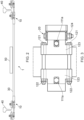
Figures 4a and 4b are schematics of an example of an adjustable clamp; -
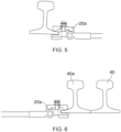
Figure 5 is a schematic of an example of a rail clamp; and -
Figure 6 is a schematic of an example of a rail clamp assembly attached to a guard rail. - In the present disclosure, there is provided a rail clamp connector which may be used to mount equipment between sleepers on ballasted track, or in between rail fastenings on slab or ballastless track, which equipment is retained in place by clamping to the foot of the rail. A railway rail may include a head, web (middle connecting portion) and foot. In order to attach equipment at a desired location to the rail, there may be provided a rail clamp. Such a clamp may be attachable around the foot of the rail. A rail clamp may then be connected to a beam, such as an equipment mount beam, via a rail clamp connector. The rail clamp connector may be part of the rail clamp or may be separate to the rail clamp. A rail clamp may be provided on each rail of a railway track, with a beam mounted between the two clamps and attached to both clamps by two rail clamp connectors. A rail clamp assembly, which may also be described as an equipment mounting assembly, may for example include the rail clamps, connectors and beam. In an example, a rail clamp may include parts which extend around both sides of the foot of a rail or a part attaching/clamping onto one side of the rail, which may for example be the inner side of the rail, facing the other rail, on a railway track having two rails.
- The rail clamp connector may provide a pivotal connection so that the rail clamp may pivot relative to the beam. Providing such a pivotal connection allows the rail clamp assembly to be adjusted during installation to compensate for any rail leaning, so as to provide an appropriate attachment to a leaning rail. Further, providing a pivotal connection with a vibration damping device may allow any equipment mounted to the beam to be held while experiencing less movement resulting from the rail leaning (cant) as the pivot allows the rail and clamp to move while the beam and equipment remain relatively still. The beam may be attached to the rail clamp connector by any suitable means. For example, the beam may be attached to the rail clamp connector by fitting to a yoke end (clevis end). Equipment may be attached to the beam by any suitable means, for example a fastener or clamp. The beam may comprise a length of glass reinforced plastic (GRP). The beam may provide electrical isolation and resilience to shock as well as further vibration damping.
- The rail clamp connector may for example be made primarily of stainless steel. GRP and stainless steel may provide a rail clamp assembly that is highly resistant to chemical and biological substances.
- In an example, as shown in
Figure 1 , there is provided arail clamp connector 10. Therail clamp connector 10 may connect arail clamp 20 to abeam 30 and therail clamp connector 10 may comprise afirst part 11a connectable to thebeam 30. Therail clamp connector 10 may further comprise asecond part 11b, pivotally connected to thefirst part 11a at a pivotal connection. Thesecond part 11b may be connectable to therail clamp 20. Therail clamp connector 10 may further comprise avibration damping device 13 to reduce the transmittal of vibration from thesecond part 11b to thefirst part 11a. In an example, therail clamp connector 10 may further comprise a fixing device (124 - shown inFigure 3 ) to restrict relative movement of the first part and the second part at the pivotal connection. Such a fixing device may attach to thevibration damping device 13. In an example, the fixingdevice 124 may comprise a through bolt and locking nut. - The
second part 11b may be pivotally connected to thefirst part 11a by a clevis joint and the dampingdevice 13 may be an elastic member or a resiliently deformable member. The member may for example preferably be made of rubber. - In an example, the
vibration damping device 13 may provide vibration damping to reduce the transmittal of vibration from thefirst part 11a to thesecond part 11b. While thevibration damping device 13 may reduce the transmission of vibrations from thesecond part 11b to thefirst part 11a, thevibration damping device 13 may also reduce vibrations in the opposite direction. Vibration damping may beneficially reduce the vibrations experienced by equipment mounted on the beam, which are created by normal railway use, such as a train passing on the rail over the rail clamp. In an example, the pivotal connection, which may be a clevis joint including apin 12 surrounded by rubber bushes as the dampingdevice 13, isolating the male and female parts.Rubber bushes 13 may improve shock and vibration resistance to whatever equipment may be mounted on the beam, from the shock and vibration input by traffic running on the rail. - In an example, as shown in
Figure 2 , there is provided a rail clamp assembly or system 1. The rail clamp assembly 1 may comprise therail clamp connector 10 as described above. The rail clamp assembly 1 may further comprise anadjustable rail clamp 20 connectable to an underside of arail 40. In an example, arail clamp 20 for attachment around the foot of arail 40 may be part of the rail clamp assembly 1. The rail clamp assembly 1 may provide connection means to connect abeam 30, on whichequipment 50 may be mounted, to arail 40. - The rail clamp assembly 1 may provide means for fixing or mounting
equipment 50, such as sensors, betweenrails 40 of a railway line. The rail clamp assembly 1 may for example include two rail clamps 20 for attachment to twoparallel rails 40. The rail clamps 20 may each be connected by arail clamp connector 10 to either side of abeam 30. Thebeam 30 may extend from onerail clamp connector 10 to the other, so that the rail clamp assembly 1 may hold thebeam 30 in place, extending between therails 40. Therefore,equipment 50 may be mounted in the space between therails 40, on thebeam 30. Providing arail clamp connector 10 at either side of thebeam 30, between thebeam 30 and eachrail 40, may beneficially make installation easier as the assembly 1 may be more easily manoeuvred into place and/or reduce movement of theequipment 50 when mounted to thebeam 30. This arrangement may allow for installation on leaning rails and allow therails 40 to lean without the need for thebeam 30 to move or flex. The rail clamp assembly 1 may accommodate typical rail incline/lean/cant, such as 1:20, 1:30, 1:40 or vertical rail, but therail clamp connector 10 may allow for total adjustability for cant. - In an example, the
rail clamp 20 may be adjustable in width to be connectable around the underside ofrails 40 of differing widths. Therail clamp 20 may for example includefasteners rail clamp 20 may pass around the foot ofrails 40 having different foot widths. In an example, the rail clamp may be connectable to one side of a foot of a rail only. - In a further example, the rail clamp assembly 1 may further comprise a
beam 30 connectable to thefirst part 11a. In use, thebeam 30 may extend above the underside of therail 40. It may be beneficial to reduce how far the rail clamp assembly 1 protrudes beneath therail 40. Components such as thebeam 30 may have a relatively large cross section, making their positioning relative to therail 40 a consideration when reducing the dimensions of the assembly 1 below therail 40. In this example, thebeam 30 may extend away from therail clamp connector 10 while only extending partly beneath the foot of therail 40 or not extending beneath the foot of therail 40 at all. In an example, a centreline of thebeam 30 may be substantially in line with the bottom surface of therail 40, when therail 40 is in a vertical orientation and therefore the bottom surface of therail 40 horizontal. - In an example, as shown in
Figure 3 , which shows the underside of therail clamp 20, therail clamp 20 may be adjustable in width. The width may be adjusted by appropriate tightening/untightening of throughbolts 121 that pass under therail 40. Thebolts 121 may allow for adjustment over any desired range of rail foot widths. In some examples, the range may include 100mm to 155mm rail foot widths. Thebolts 121 may be fastened by correspondingnuts 122, such as locking nuts. - The
rail clamp 20 may clamp arail 40 in place by positioning the rail foot between aclamp plate 112 and aclamp seat 123. Theclamp plate 112 and clampseat 123 may be held together bybolts 111, described in more detail below. - The
rail clamp 20 may further be adjustable for different foot heights. As shown inFigure 1 , therail clamp 20 may be adjusted by a convex 'arched' washer arrangement, in the concave 'arched' housing of the clamp seat. Therefore, various rail foot heights may be accommodated by the rail clamp. - In an example, the
rail clamp 20 may comprise pivotally attachable fasteners to clamp a foot of therail 40. Therail clamp 20 may include a portion arranged to extend at least partly over the foot of the rail, so that, when tightened, the portion holds or clamps onto the rail. In an example, therail clamp connector 10 may be fixed in place by a fixingdevice 124 to restrict relative movement of the first part and the second part at the pivotal connection. The fixingdevice 124 may for example comprise a through bolt and locking nut. - As shown in
Figures 4a and 4b , in some examples therail clamp 20 may provide a clamp or fastener which may attach to arail 40 and therail clamp connector 10. Therail clamp 20 may include aclamp bolt 111 which passes through theclamp seat 123, through thesecond part 11b of therail clamp connector 10, through aclamp plate 112 and engages with anut 113, such as a hardlock nut. Thesecond part 11b of therail clamp connector 10 defines an arched or concave housing for thebolt head 111a. Between thebolt head 111a and the concave housing of thesecond part 11b there is provided an arched orconvex washer 114 which allows thebolt 111 to pivot relative to thesecond part 11b of therail clamp connector 10. In another example, thebolt head 111a may be arched or convex, in a similar shape to the washer, so as to allow thebolt 111 to pivot relative to thesecond part 11b of therail clamp connector 10. As shown inFigure 4a , thebolt 111 may pivot slightly clockwise (as shown in the figure) to clamp onto a rail foot having a height of 6mm and may pivot slightly anticlockwise, as shown inFigure 4b to accommodate a rail foot having a greater height, so as 16mm in the example shown. The values shown in the figures are exemplary and only used for explanation. The fasteners, such as nut and bolt-type fasteners, being able to pivot may ensure than the clamp is firmly securable around the foot of the rail by aligning the head of the bolt, and the nut, respectively, with the surfaces of the clamp seat and clamp plate. - In an example, as shown in
Figure 5 , arail clamp 20a may clamp arail 40 in place by positioning the rail foot between a clamp plate and a clamp seat, as shown inFigures 4a and 4b . In the example shown inFigure 5 , therail clamp 20a only clamps to one side of the rail. For example, therail clamp 20 may comprise tworail clamps 20a, connected together by one or more fasteners, which, in situ, may pass underneath therail 40. - In an example, as shown in
Figure 6 , therail clamp 20a may clamp to aguard rail 40a. Theguard rail 40a may normally run next to the runningrail 40, on the inside (between the two running rails 40). In this example, thebeam 30 may be correspondingly shorter than if attached between the two runningrails 40. Theguard rail 40a may for example be oriented vertically, whereas the runningrail 40 may lean. With therail clamp connector 10 as described above in a rail clamp assembly 1, the assembly 1 may be mounted onto a runningrail 40 which is leaning at one end and aguard rail 40a, which is vertical (the foot thus being horizontal), at the other end. - While the apparatus and related aspects have been described with reference to certain examples, various modifications, changes, omissions, and substitutions can be made without departing from the invention, the invention being defined by the following claims. It should be noted that the above-mentioned examples illustrate rather than limit what is described herein, and that those skilled in the art will be able to design many alternative implementations without departing from the scope of the appended claims.
- The word "comprising" does not exclude the presence of elements other than those listed in a claim, "a" or "an" does not exclude a plurality, and a single processor or other unit may fulfil the functions of several units recited in the claims.
Claims (12)
- A rail clamp connector (10), for connecting a rail clamp (20; 20a) to a beam (30), the rail clamp connector (10) comprising:a first part (11a) connectable to the beam (30);characterised in that the rail clamp connector further comprises:a second part (11b) connectable to the rail clamp (20; 20a), the second part (11b) being pivotally connected to the first part (11a) by virtue of a pivotal connection such that the first part (11a) is adjustable to compensate for leaning of a rail (40; 40a) to which the rail clamp (20) is connectable when in use; anda vibration damping device (13) to reduce the transmittal of vibration from the second part (11b) to the first part (11a).
- The rail clamp connector of claim 1, wherein
the second part (11b) is pivotally connected to the first part (11a) by a clevis joint (12). - The rail clamp connector of any preceding claim, wherein
the vibration damping device (13) is an elastic member. - The rail clamp connector of any preceding claim, wherein
the vibration damping device (13) is a resiliently deformable member. - The rail clamp connector of claim 3 or claim 4, wherein
the elastic and/or resiliently deformable member is made of rubber. - The rail clamp connector of any preceding claim, further comprising:
a fixing device (124) to restrict relative movement of the first part (11a) and the second part (11b) at the pivotal connection. - A rail clamp assembly (1) comprising:the rail clamp connector (10) of any preceding claim; andan adjustable rail clamp (20; 20a) connectable to an underside of a rail (40; 40a).
- The rail clamp assembly of claim 7, wherein
the rail clamp (20; 20a) is adjustable in width to be connectable around the underside of rails (40; 40a) of differing widths. - The rail clamp assembly of claim 7 or claim 8, further comprising:a beam (30) connectable to the first part (11a), whereinin use, the beam (30) extends above the underside of the rail (40; 40a).
- The rail clamp assembly of any of claims 7-9, wherein
the rail clamp (20; 20a) comprises pivotally attachable fasteners to clamp to a foot of the rail (40; 40a). - A rail clamp assembly (1) comprising:the rail clamp connector (10) of any of claims 1-6; andan adjustable rail clamp (20; 20a) connectable to a side of a foot of a rail (40; 40a), wherein the rail is a running rail (40) or a guard rail (40a).
- A rail clamp assembly (1) comprising:a beam (30);a first rail clamp connector (10) of any of claims 1 - 6 attached to one end of the beam (30);a second rail clamp connector (10) of any of claims 1 - 6 attached to the other end of the beam (30);a first adjustable rail clamp (20; 20a) connected at one side to the first rail clamp connector (10) and at the other side to a side of a foot of a first rail (40; 40a); anda second adjustable rail clamp (20; 20a) connected at one side to the second rail clamp connector (10) and at the other side to a side of a foot of a second rail (40; 40a).
Applications Claiming Priority (2)
| Application Number | Priority Date | Filing Date | Title |
|---|---|---|---|
| GB1906254.6A GB2583722B (en) | 2019-05-03 | 2019-05-03 | Rail clamp connector |
| PCT/EP2020/061796 WO2020225037A1 (en) | 2019-05-03 | 2020-04-28 | Rail clamp connector |
Publications (3)
| Publication Number | Publication Date |
|---|---|
| EP3963136A1 EP3963136A1 (en) | 2022-03-09 |
| EP3963136B1 true EP3963136B1 (en) | 2024-03-13 |
| EP3963136C0 EP3963136C0 (en) | 2024-03-13 |
Family
ID=67384890
Family Applications (1)
| Application Number | Title | Priority Date | Filing Date |
|---|---|---|---|
| EP20723329.7A Active EP3963136B1 (en) | 2019-05-03 | 2020-04-28 | Rail clamp connector |
Country Status (7)
| Country | Link |
|---|---|
| US (1) | US12371859B2 (en) |
| EP (1) | EP3963136B1 (en) |
| AU (1) | AU2020269210B2 (en) |
| ES (1) | ES2980816T3 (en) |
| GB (1) | GB2583722B (en) |
| PL (1) | PL3963136T3 (en) |
| WO (1) | WO2020225037A1 (en) |
Cited By (1)
| Publication number | Priority date | Publication date | Assignee | Title |
|---|---|---|---|---|
| US20220235520A1 (en) * | 2019-05-03 | 2022-07-28 | Pandrol (Vortok) Ltd | Rail clamp connector |
Family Cites Families (17)
| Publication number | Priority date | Publication date | Assignee | Title |
|---|---|---|---|---|
| US1468532A (en) * | 1923-04-11 | 1923-09-18 | Korba Alex | Rail chair |
| US4753403A (en) * | 1986-12-08 | 1988-06-28 | American Standard Inc. | Railroad track mounting arrangement |
| US4799444A (en) * | 1987-10-01 | 1989-01-24 | Helm Products, Inc. | Rail clamp |
| US4824015A (en) * | 1987-11-06 | 1989-04-25 | Abc Rail Corporation | Rail brace |
| GB9826674D0 (en) * | 1998-12-03 | 1999-01-27 | Multiclip Co Ltd | Securing an aerial fixation assembly to a railway rail foundation |
| BE1014197A3 (en) * | 2001-02-16 | 2003-06-03 | Dirven Stuphane | Rail and elastic jacket assembly e.g. for tramlines is made in a a cavity in a cast constructional material such as concrete |
| AUPR827501A0 (en) * | 2001-10-16 | 2001-11-08 | Robertson, Malcolm | Fastrax quicktwist guardrail system |
| DE20300537U1 (en) * | 2003-01-14 | 2003-06-18 | Agrar-Technik Mangelsdorf GmbH, 39524 Mangelsdorf | Device for fixing mobile blocking devices on rail tracks comprises a clamping device designed as a two-piece hinge which is hinged with one free end on a sliding component and is supported with its other free end against an abutment |
| GB2431956A (en) | 2005-11-02 | 2007-05-09 | Balfour Beatty Plc | Rail bearer joint and rail baseplate for use in the joint |
| DE102007046543A1 (en) * | 2007-09-27 | 2009-04-16 | Vossloh-Werke Gmbh | System for securing a rail and tension clamp for such a system |
| GB2471277B (en) * | 2009-06-22 | 2016-04-27 | Multiclip Co Ltd | Equipment mounting assembly |
| KR20120123763A (en) * | 2011-05-02 | 2012-11-12 | 한국철도공사 | Coupling apparatus for the tip of tongue rail |
| KR20140143246A (en) * | 2013-06-05 | 2014-12-16 | (주) 주은산업 | balise holding device for automatic train protection |
| EP3318444A1 (en) * | 2016-11-07 | 2018-05-09 | Dubuis et Cie | Rail clamp |
| GB2583722B (en) * | 2019-05-03 | 2022-05-18 | Pandrol Vortok Ltd | Rail clamp connector |
| WO2023108194A1 (en) * | 2021-12-14 | 2023-06-22 | Cold Forged Products No. 1 Pty Limited | Rail clamp |
| CN221589089U (en) * | 2024-01-04 | 2024-08-23 | 中铁第一勘察设计院集团有限公司 | Railway line curve section reinforcing rail clamp device with insulating piece |
-
2019
- 2019-05-03 GB GB1906254.6A patent/GB2583722B/en not_active Expired - Fee Related
-
2020
- 2020-04-28 US US17/608,364 patent/US12371859B2/en active Active
- 2020-04-28 EP EP20723329.7A patent/EP3963136B1/en active Active
- 2020-04-28 PL PL20723329.7T patent/PL3963136T3/en unknown
- 2020-04-28 AU AU2020269210A patent/AU2020269210B2/en active Active
- 2020-04-28 ES ES20723329T patent/ES2980816T3/en active Active
- 2020-04-28 WO PCT/EP2020/061796 patent/WO2020225037A1/en not_active Ceased
Cited By (2)
| Publication number | Priority date | Publication date | Assignee | Title |
|---|---|---|---|---|
| US20220235520A1 (en) * | 2019-05-03 | 2022-07-28 | Pandrol (Vortok) Ltd | Rail clamp connector |
| US12371859B2 (en) * | 2019-05-03 | 2025-07-29 | Pandrol (Vortok) Ltd | Rail clamp connector |
Also Published As
| Publication number | Publication date |
|---|---|
| GB2583722A (en) | 2020-11-11 |
| WO2020225037A1 (en) | 2020-11-12 |
| GB2583722B (en) | 2022-05-18 |
| EP3963136C0 (en) | 2024-03-13 |
| EP3963136A1 (en) | 2022-03-09 |
| ES2980816T3 (en) | 2024-10-03 |
| PL3963136T3 (en) | 2024-09-09 |
| GB201906254D0 (en) | 2019-06-19 |
| US20220235520A1 (en) | 2022-07-28 |
| US12371859B2 (en) | 2025-07-29 |
| AU2020269210A1 (en) | 2021-11-11 |
| CA3137782A1 (en) | 2020-11-12 |
| AU2020269210B2 (en) | 2025-01-30 |
Similar Documents
| Publication | Publication Date | Title |
|---|---|---|
| US9010655B2 (en) | System for securing a rail on level solid ground | |
| US8602317B2 (en) | Support for a system for fastening a rail and a system for fastening a rail | |
| JP2022502584A (en) | bracket | |
| US7140157B2 (en) | Foundation system for beam of manufactured home | |
| EP3488049B1 (en) | Mechanism and system for fastening track rail to a substrate and track rail fastening method | |
| IL204527A (en) | System for fastening a rail and tensioning clamp for a system to this type | |
| EP2522400A2 (en) | Support post assembly for a safety line system | |
| AU2020269210B2 (en) | Rail clamp connector | |
| JP2002331935A (en) | Ground mounting bracket | |
| US20200378069A1 (en) | Rail Fastening System | |
| US8864084B2 (en) | Railway track switch cover system | |
| US6648276B1 (en) | Drop down lug for railroad switch application | |
| CA3137782C (en) | Rail clamp connector | |
| EP0376594B1 (en) | Rail-fastening for rails | |
| KR20140000963U (en) | Rail fastening apparatus | |
| JP5424149B2 (en) | Planting installation structure | |
| KR101859876B1 (en) | Anchor apparatus capable of changing the installation position of an anchor socket and apparatus for supporting a structure utilizing the same | |
| EP3695458A1 (en) | Adjustable antenna mounting system | |
| KR101961617B1 (en) | Multi-purpose fixture body for balise | |
| CN212011230U (en) | Antenna protection box of railway vehicle number identification system | |
| KR20170075480A (en) | Apparatus for supporting railway | |
| RU2300598C1 (en) | Direct fixation rail fastening for track on reinforced concrete base | |
| JP4732635B2 (en) | Mounting bracket for control equipment | |
| KR20150109627A (en) | Adjustable pads for railway rails fixture | |
| KR102752002B1 (en) | Temporary support device for piping support of offshore structures |
Legal Events
| Date | Code | Title | Description |
|---|---|---|---|
| STAA | Information on the status of an ep patent application or granted ep patent |
Free format text: STATUS: UNKNOWN |
|
| STAA | Information on the status of an ep patent application or granted ep patent |
Free format text: STATUS: THE INTERNATIONAL PUBLICATION HAS BEEN MADE |
|
| PUAI | Public reference made under article 153(3) epc to a published international application that has entered the european phase |
Free format text: ORIGINAL CODE: 0009012 |
|
| STAA | Information on the status of an ep patent application or granted ep patent |
Free format text: STATUS: REQUEST FOR EXAMINATION WAS MADE |
|
| 17P | Request for examination filed |
Effective date: 20211011 |
|
| AK | Designated contracting states |
Kind code of ref document: A1 Designated state(s): AL AT BE BG CH CY CZ DE DK EE ES FI FR GB GR HR HU IE IS IT LI LT LU LV MC MK MT NL NO PL PT RO RS SE SI SK SM TR |
|
| RIN1 | Information on inventor provided before grant (corrected) |
Inventor name: MULVAY, CRAIG Inventor name: ALGAR, NEIL Inventor name: GRIMWADE, DAVID JAMES |
|
| DAV | Request for validation of the european patent (deleted) | ||
| DAX | Request for extension of the european patent (deleted) | ||
| STAA | Information on the status of an ep patent application or granted ep patent |
Free format text: STATUS: EXAMINATION IS IN PROGRESS |
|
| 17Q | First examination report despatched |
Effective date: 20230202 |
|
| RAP3 | Party data changed (applicant data changed or rights of an application transferred) |
Owner name: PANDROL (VORTOK) LIMITED |
|
| REG | Reference to a national code |
Ref country code: DE Ref legal event code: R079 Free format text: PREVIOUS MAIN CLASS: E01B0005160000 Ipc: B61L0001020000 Ref document number: 602020027175 Country of ref document: DE |
|
| GRAP | Despatch of communication of intention to grant a patent |
Free format text: ORIGINAL CODE: EPIDOSNIGR1 |
|
| STAA | Information on the status of an ep patent application or granted ep patent |
Free format text: STATUS: GRANT OF PATENT IS INTENDED |
|
| RIC1 | Information provided on ipc code assigned before grant |
Ipc: E01B 26/00 20060101ALI20230908BHEP Ipc: E01B 5/16 20060101ALI20230908BHEP Ipc: B61L 3/12 20060101ALI20230908BHEP Ipc: B61L 1/02 20060101AFI20230908BHEP |
|
| INTG | Intention to grant announced |
Effective date: 20231006 |
|
| GRAS | Grant fee paid |
Free format text: ORIGINAL CODE: EPIDOSNIGR3 |
|
| GRAA | (expected) grant |
Free format text: ORIGINAL CODE: 0009210 |
|
| STAA | Information on the status of an ep patent application or granted ep patent |
Free format text: STATUS: THE PATENT HAS BEEN GRANTED |
|
| AK | Designated contracting states |
Kind code of ref document: B1 Designated state(s): AL AT BE BG CH CY CZ DE DK EE ES FI FR GB GR HR HU IE IS IT LI LT LU LV MC MK MT NL NO PL PT RO RS SE SI SK SM TR |
|
| REG | Reference to a national code |
Ref country code: GB Ref legal event code: FG4D |
|
| REG | Reference to a national code |
Ref country code: CH Ref legal event code: EP |
|
| REG | Reference to a national code |
Ref country code: DE Ref legal event code: R096 Ref document number: 602020027175 Country of ref document: DE |
|
| REG | Reference to a national code |
Ref country code: IE Ref legal event code: FG4D |
|
| U01 | Request for unitary effect filed |
Effective date: 20240313 |
|
| U07 | Unitary effect registered |
Designated state(s): AT BE BG DE DK EE FI FR IT LT LU LV MT NL PT SE SI Effective date: 20240322 |
|
| PG25 | Lapsed in a contracting state [announced via postgrant information from national office to epo] |
Ref country code: GR Free format text: LAPSE BECAUSE OF FAILURE TO SUBMIT A TRANSLATION OF THE DESCRIPTION OR TO PAY THE FEE WITHIN THE PRESCRIBED TIME-LIMIT Effective date: 20240614 |
|
| PG25 | Lapsed in a contracting state [announced via postgrant information from national office to epo] |
Ref country code: RS Free format text: LAPSE BECAUSE OF FAILURE TO SUBMIT A TRANSLATION OF THE DESCRIPTION OR TO PAY THE FEE WITHIN THE PRESCRIBED TIME-LIMIT Effective date: 20240613 Ref country code: HR Free format text: LAPSE BECAUSE OF FAILURE TO SUBMIT A TRANSLATION OF THE DESCRIPTION OR TO PAY THE FEE WITHIN THE PRESCRIBED TIME-LIMIT Effective date: 20240313 |
|
| U20 | Renewal fee for the european patent with unitary effect paid |
Year of fee payment: 5 Effective date: 20240620 |
|
| PG25 | Lapsed in a contracting state [announced via postgrant information from national office to epo] |
Ref country code: RS Free format text: LAPSE BECAUSE OF FAILURE TO SUBMIT A TRANSLATION OF THE DESCRIPTION OR TO PAY THE FEE WITHIN THE PRESCRIBED TIME-LIMIT Effective date: 20240613 Ref country code: HR Free format text: LAPSE BECAUSE OF FAILURE TO SUBMIT A TRANSLATION OF THE DESCRIPTION OR TO PAY THE FEE WITHIN THE PRESCRIBED TIME-LIMIT Effective date: 20240313 Ref country code: GR Free format text: LAPSE BECAUSE OF FAILURE TO SUBMIT A TRANSLATION OF THE DESCRIPTION OR TO PAY THE FEE WITHIN THE PRESCRIBED TIME-LIMIT Effective date: 20240614 |
|
| REG | Reference to a national code |
Ref country code: ES Ref legal event code: FG2A Ref document number: 2980816 Country of ref document: ES Kind code of ref document: T3 Effective date: 20241003 |
|
| PG25 | Lapsed in a contracting state [announced via postgrant information from national office to epo] |
Ref country code: IS Free format text: LAPSE BECAUSE OF FAILURE TO SUBMIT A TRANSLATION OF THE DESCRIPTION OR TO PAY THE FEE WITHIN THE PRESCRIBED TIME-LIMIT Effective date: 20240713 |
|
| PG25 | Lapsed in a contracting state [announced via postgrant information from national office to epo] |
Ref country code: SM Free format text: LAPSE BECAUSE OF FAILURE TO SUBMIT A TRANSLATION OF THE DESCRIPTION OR TO PAY THE FEE WITHIN THE PRESCRIBED TIME-LIMIT Effective date: 20240313 |
|
| PG25 | Lapsed in a contracting state [announced via postgrant information from national office to epo] |
Ref country code: SK Free format text: LAPSE BECAUSE OF FAILURE TO SUBMIT A TRANSLATION OF THE DESCRIPTION OR TO PAY THE FEE WITHIN THE PRESCRIBED TIME-LIMIT Effective date: 20240313 |
|
| PG25 | Lapsed in a contracting state [announced via postgrant information from national office to epo] |
Ref country code: SM Free format text: LAPSE BECAUSE OF FAILURE TO SUBMIT A TRANSLATION OF THE DESCRIPTION OR TO PAY THE FEE WITHIN THE PRESCRIBED TIME-LIMIT Effective date: 20240313 Ref country code: SK Free format text: LAPSE BECAUSE OF FAILURE TO SUBMIT A TRANSLATION OF THE DESCRIPTION OR TO PAY THE FEE WITHIN THE PRESCRIBED TIME-LIMIT Effective date: 20240313 Ref country code: RO Free format text: LAPSE BECAUSE OF FAILURE TO SUBMIT A TRANSLATION OF THE DESCRIPTION OR TO PAY THE FEE WITHIN THE PRESCRIBED TIME-LIMIT Effective date: 20240313 Ref country code: IS Free format text: LAPSE BECAUSE OF FAILURE TO SUBMIT A TRANSLATION OF THE DESCRIPTION OR TO PAY THE FEE WITHIN THE PRESCRIBED TIME-LIMIT Effective date: 20240713 |
|
| REG | Reference to a national code |
Ref country code: DE Ref legal event code: R097 Ref document number: 602020027175 Country of ref document: DE |
|
| PG25 | Lapsed in a contracting state [announced via postgrant information from national office to epo] |
Ref country code: MC Free format text: LAPSE BECAUSE OF FAILURE TO SUBMIT A TRANSLATION OF THE DESCRIPTION OR TO PAY THE FEE WITHIN THE PRESCRIBED TIME-LIMIT Effective date: 20240313 |
|
| PLBE | No opposition filed within time limit |
Free format text: ORIGINAL CODE: 0009261 |
|
| STAA | Information on the status of an ep patent application or granted ep patent |
Free format text: STATUS: NO OPPOSITION FILED WITHIN TIME LIMIT |
|
| PG25 | Lapsed in a contracting state [announced via postgrant information from national office to epo] |
Ref country code: MC Free format text: LAPSE BECAUSE OF FAILURE TO SUBMIT A TRANSLATION OF THE DESCRIPTION OR TO PAY THE FEE WITHIN THE PRESCRIBED TIME-LIMIT Effective date: 20240313 |
|
| 26N | No opposition filed |
Effective date: 20241216 |
|
| PG25 | Lapsed in a contracting state [announced via postgrant information from national office to epo] |
Ref country code: IE Free format text: LAPSE BECAUSE OF NON-PAYMENT OF DUE FEES Effective date: 20240428 |
|
| U20 | Renewal fee for the european patent with unitary effect paid |
Year of fee payment: 6 Effective date: 20250428 |
|
| PGFP | Annual fee paid to national office [announced via postgrant information from national office to epo] |
Ref country code: ES Payment date: 20250507 Year of fee payment: 6 |
|
| PGFP | Annual fee paid to national office [announced via postgrant information from national office to epo] |
Ref country code: CH Payment date: 20250501 Year of fee payment: 6 |
|
| PG25 | Lapsed in a contracting state [announced via postgrant information from national office to epo] |
Ref country code: CY Free format text: LAPSE BECAUSE OF FAILURE TO SUBMIT A TRANSLATION OF THE DESCRIPTION OR TO PAY THE FEE WITHIN THE PRESCRIBED TIME-LIMIT; INVALID AB INITIO Effective date: 20200428 |
|
| PG25 | Lapsed in a contracting state [announced via postgrant information from national office to epo] |
Ref country code: HU Free format text: LAPSE BECAUSE OF FAILURE TO SUBMIT A TRANSLATION OF THE DESCRIPTION OR TO PAY THE FEE WITHIN THE PRESCRIBED TIME-LIMIT; INVALID AB INITIO Effective date: 20200428 |
|
| PGFP | Annual fee paid to national office [announced via postgrant information from national office to epo] |
Ref country code: GB Payment date: 20260327 Year of fee payment: 7 |
|
| PGFP | Annual fee paid to national office [announced via postgrant information from national office to epo] |
Ref country code: NO Payment date: 20260326 Year of fee payment: 7 |
|
| PGFP | Annual fee paid to national office [announced via postgrant information from national office to epo] |
Ref country code: CZ Payment date: 20260316 Year of fee payment: 7 |
|
| PGFP | Annual fee paid to national office [announced via postgrant information from national office to epo] |
Ref country code: PL Payment date: 20260320 Year of fee payment: 7 |
|
| REG | Reference to a national code |
Ref country code: CH Ref legal event code: U11 Free format text: ST27 STATUS EVENT CODE: U-0-0-U10-U11 (AS PROVIDED BY THE NATIONAL OFFICE) Effective date: 20260501 |