EP3962810B1 - Aktuatoranordnung für ein festes eintrittskantelement einer flugzeugflügelanordnung und flugzeug mit dieser betätigungsvorrichtung - Google Patents
Aktuatoranordnung für ein festes eintrittskantelement einer flugzeugflügelanordnung und flugzeug mit dieser betätigungsvorrichtung Download PDFInfo
- Publication number
- EP3962810B1 EP3962810B1 EP20771850.3A EP20771850A EP3962810B1 EP 3962810 B1 EP3962810 B1 EP 3962810B1 EP 20771850 A EP20771850 A EP 20771850A EP 3962810 B1 EP3962810 B1 EP 3962810B1
- Authority
- EP
- European Patent Office
- Prior art keywords
- actuator
- assembly
- drive unit
- lift device
- wing assembly
- Prior art date
- Legal status (The legal status is an assumption and is not a legal conclusion. Google has not performed a legal analysis and makes no representation as to the accuracy of the status listed.)
- Active
Links
Images






Classifications
-
- B—PERFORMING OPERATIONS; TRANSPORTING
- B64—AIRCRAFT; AVIATION; COSMONAUTICS
- B64C—AEROPLANES; HELICOPTERS
- B64C13/00—Control systems or transmitting systems for actuating flying-control surfaces, lift-increasing flaps, air brakes, or spoilers
- B64C13/24—Transmitting means
- B64C13/26—Transmitting means without power amplification or where power amplification is irrelevant
- B64C13/28—Transmitting means without power amplification or where power amplification is irrelevant mechanical
- B64C13/30—Transmitting means without power amplification or where power amplification is irrelevant mechanical using cable, chain, or rod mechanisms
-
- B—PERFORMING OPERATIONS; TRANSPORTING
- B64—AIRCRAFT; AVIATION; COSMONAUTICS
- B64C—AEROPLANES; HELICOPTERS
- B64C9/00—Adjustable control surfaces or members, e.g. rudders
- B64C9/14—Adjustable control surfaces or members, e.g. rudders forming slots
- B64C9/22—Adjustable control surfaces or members, e.g. rudders forming slots at the front of the wing
-
- B—PERFORMING OPERATIONS; TRANSPORTING
- B64—AIRCRAFT; AVIATION; COSMONAUTICS
- B64C—AEROPLANES; HELICOPTERS
- B64C13/00—Control systems or transmitting systems for actuating flying-control surfaces, lift-increasing flaps, air brakes, or spoilers
- B64C13/24—Transmitting means
- B64C13/26—Transmitting means without power amplification or where power amplification is irrelevant
- B64C13/28—Transmitting means without power amplification or where power amplification is irrelevant mechanical
- B64C13/34—Transmitting means without power amplification or where power amplification is irrelevant mechanical using toothed gearing
-
- B—PERFORMING OPERATIONS; TRANSPORTING
- B64—AIRCRAFT; AVIATION; COSMONAUTICS
- B64C—AEROPLANES; HELICOPTERS
- B64C13/00—Control systems or transmitting systems for actuating flying-control surfaces, lift-increasing flaps, air brakes, or spoilers
- B64C13/24—Transmitting means
- B64C13/26—Transmitting means without power amplification or where power amplification is irrelevant
- B64C13/28—Transmitting means without power amplification or where power amplification is irrelevant mechanical
-
- B—PERFORMING OPERATIONS; TRANSPORTING
- B64—AIRCRAFT; AVIATION; COSMONAUTICS
- B64C—AEROPLANES; HELICOPTERS
- B64C13/00—Control systems or transmitting systems for actuating flying-control surfaces, lift-increasing flaps, air brakes, or spoilers
- B64C13/24—Transmitting means
- B64C13/38—Transmitting means with power amplification
-
- B—PERFORMING OPERATIONS; TRANSPORTING
- B64—AIRCRAFT; AVIATION; COSMONAUTICS
- B64C—AEROPLANES; HELICOPTERS
- B64C9/00—Adjustable control surfaces or members, e.g. rudders
- B64C9/14—Adjustable control surfaces or members, e.g. rudders forming slots
- B64C9/22—Adjustable control surfaces or members, e.g. rudders forming slots at the front of the wing
- B64C9/24—Adjustable control surfaces or members, e.g. rudders forming slots at the front of the wing by single flap
-
- B—PERFORMING OPERATIONS; TRANSPORTING
- B64—AIRCRAFT; AVIATION; COSMONAUTICS
- B64C—AEROPLANES; HELICOPTERS
- B64C9/00—Adjustable control surfaces or members, e.g. rudders
- B64C9/14—Adjustable control surfaces or members, e.g. rudders forming slots
- B64C9/22—Adjustable control surfaces or members, e.g. rudders forming slots at the front of the wing
- B64C9/26—Adjustable control surfaces or members, e.g. rudders forming slots at the front of the wing by multiple flaps
Definitions
- the invention relates to an actuator arrangement for a fixed leading edge member of an aircraft. Furthermore, the invention relates to a wing assembly and an aircraft equipped with such an actuator arrangement.
- slat actuation architectures have a static geared rotary actuator (GRA) that drives the slat via a pinon.
- GAA static geared rotary actuator
- lever bearing assemblies are preferred.
- US 4 979 700 A discloses a typical GRA for a leading edge of an aircraft.
- EP 3 378 762 A1 discloses a wing for an aircraft, comprising a main wing, a slat, and a connection assembly for movably connecting the slat to the main wing.
- the connection assembly comprises a drive unit provided at the main wing and connected to the slat for initiating movement of the slat.
- the drive unit comprises a plurality of drive stations spaced apart from one another in the wing span direction.
- WO 2010 / 119 280 A1 discloses a panel device for modifying airflow about a wing of an aircraft.
- the panel device comprises a plurality of independently operable panel sub-sections.
- the panel sub-section is coupled to the trailing edge of the wing by a linkage mechanism.
- the linkage mechanism comprises an actuator coupled to a trapezoidal frame by a mechanical linkage.
- the actuator is fixed to the wing at the trailing edge. Activation of the actuator is operable to raise and lower the relative position of the panel sub-section with respect to the wing.
- US 3 128 966 A discloses a high-lift system for aircraft wings.
- the leading edge device comprises a worm and linkage system in which pivoted scissors are pivoted at one of their ends.
- the scissors connect to a lower flap door and a fixed bracket respectively.
- the scissors connect to a nut-and-bracket device driven by a turning screw.
- the turning screw results in translation of the nut-and-bracket device, angular displacements of the scissors, and motion of the lower flap door about its pivotal axis.
- US 3 617 018 A discloses a flap connected to a wing by a geared hinge. Extension or retraction of the flap is accomplished by an actuating and drive mechanism arranged on the flap. Upon command of an associated remotely positioned control means the actuating mechanism will via the drive mechanism drive the geared hinge connection for moving the flap into a predetermined position in reference to the wing surface.
- the invention provides a wing assembly for an aircraft, the wing assembly comprising a fixed leading edge member, a high-lift device movably attached to the fixed leading edge member, and an actuator arrangement, the actuator arrangement comprising:
- the geared rotary actuator is movable along a circular arc section in a forward direction during extending of the high-lift device and/or in an aft direction during retracting of the high-lift device.
- the geared rotary actuator when in the fully retracted position, is wholly accommodated within the inner cavity.
- the geared rotary actuator when in the fully extended position, is wholly positioned outside the inner cavity.
- the geared rotary actuator assembly includes at least two geared rotary actuators and two geared rotary actuators each are grouped together into a respective geared rotary actuator group for driving one high-lift device.
- the geared rotary actuator arrangement further comprises a drive unit providing mechanical power for driving the geared rotary actuator assembly
- the geared rotary actuator assembly includes a spanwise drive train having at least one spanwise straight drive shaft, which mechanically couples two adjacent geared rotary actuators.
- the geared rotary actuator assembly includes a first geared rotary actuator and a second geared rotary actuator, wherein the first geared rotary actuator is mechanically coupled to the drive unit.
- the first geared rotary actuator is mechanically coupled to the drive unit via a pivotable drive shaft.
- the second geared rotary actuator is mechanically coupled to the first geared rotary actuator via a spanwise straight drive shaft.
- the drive unit is arranged spanwise between adjacent geared rotary actuators associated with one high-lift device
- the drive unit is arranged on the same axis as the geared rotary actuator in a spanwise direction.
- the drive unit is arranged aft of the geared rotary actuator.
- the drive unit is arranged below the geared rotary actuator.
- the drive unit is arranged aft and below of the geared rotary actuator.
- the drive unit is arranged adjacent to the geared rotary actuator in a spanwise direction or chordwise direction.
- the drive unit is configured to be arranged predominantly, in particular entirely, within an upper half of the inner cavity in the fully retracted position.
- the drive unit is configured to be arranged partially, in particular predominantly, within a lower half of the inner cavity in the fully extended position.
- the drive unit is configured to be arranged within the inner cavity, when in the fully retracted position, in the fully extended position and when moving between said positions.
- the drive unit is configured to be arranged predominantly, in particular entirely, within a lower half of the inner cavity in the fully retracted position.
- the drive unit is configured to be arranged partially outside inner cavity in the fully extended position.
- the drive unit is configured to be arranged to protrude downward through a cut-out of the fixed leading edge member.
- the drive unit is attached to the actuator assembly, so as to be simultaneously movable.
- the drive unit has at least one motor for driving the geared rotary actuator.
- the drive unit has at least one electric motor for driving the geared rotary actuator.
- the drive unit has at least one hydraulic motor for driving the geared rotary actuator.
- one or each motor is mechanically coupled to two adjacent geared rotary actuators associated with one high-lift device, in particular via a spanwise straight drive shaft.
- one or each motor is arranged aft of and adjacent to the geared rotary actuator when viewed in a top view.
- one or each motor is arranged aft of and below the geared rotary actuator and adjacent to the geared rotary actuator when viewed in a top view.
- one or each motor is arranged on the same axis as the geared rotary actuator in a spanwise direction.
- the invention allows for a GRA to be integrated into the lever architecture.
- the stroke of the GRA may be maximized using the preferred configurations, thereby increasing efficiency. This may be achieved due to a reduction of the required forces by increasing travel, thus reducing actuation momentum.
- gear sizes within the GRA and the overall size of the GRA may be reduced. Consequently, weight and space efficiency are improved.
- the aircraft 10 comprises a fuselage 12, a vertical tail plane 14 and a horizontal tail plane 16. Furthermore, the aircraft 10 comprises a wing assembly 18, which comprises at least one high-lift device 20, such as a slat 22.
- an actuator arrangement 24 is configured to move the high-lift device 20 between a fully retracted position ( Fig. 4 ) and a fully extended position ( Fig. 5 ).
- the high-lift device 20 is movably attached to a fixed leading edge member 26 ( Fig. 3 ) using a plurality of rails 28, which are supported by roller bearings 30.
- the rails 28 are attached to the high-lift device 20 via a lever assembly 32.
- the actuator arrangement 24 comprises two fixed leading edge levers 34.
- the fixed leading edge lever 34 is mechanically coupled to the fixed leading edge member 26.
- the actuator arrangement 24 comprises a high-lift device lever 36.
- the high-lift device lever 36 is coupled to the high-lift device 20.
- the actuator arrangement 24 comprises an actuator assembly 38.
- the actuator assembly 38 is configured for driving the fixed leading edge lever 34 and the high-lift device lever 36 relative to each other, so as to extend and retract the high-lift device 20.
- the actuator assembly 38 comprises at least one actuator 40.
- the actuator 40 is preferably a geared rotary actuator 42.
- the fixed leading edge member 26 comprises in manner known per se an outer skin 44 and a plurality of ribs 46, which support the outer skin 44. Adjacent ribs 46 and the outer skin 44 define an inner cavity 48 of the fixed leading edge member 26.
- the outer skin 44 comprises so-called D-nose cut-outs 50, which allow extending and retracting the high-lift device 20 via the actuator arrangement 24 and the rails 28.
- the actuator 40 is arranged predominately inside the inner cavity 48, when in the fully retracted position ( Fig. 4 ). Furthermore, the actuator 40 is arranged predominately in an upper half of the inner cavity 48, when in the fully retracted position.
- the actuator arrangement 24 is operated. In doing so, the actuator 40 moves the fixed leading edge lever 34 relative to the high-lift device lever 36.
- the fixed leading edge lever 34 and the high-lift device lever 36 stretch in the forward aft direction.
- the angle between the fixed leading edge lever 34 and the high-lift device lever 36 is acute at the beginning and increases to be more than 90 degrees in the extended position ( Fig. 5 ).
- the actuator 40 itself follows the movement along a circular arc section 52 until the actuator 40 is arranged entirely outside the inner cavity 48, when in the fully extended position.
- the actuator 40 rotates about a rotational axis 53.
- the rotational axis 53 is defined by the mounting point of the fixed leading edge lever 34.
- the actuator arrangement 24 comprises a plurality of actuators 40.
- Each actuator 40 has an input shaft 54 and an output shaft 56.
- the actuator arrangement 24 comprises a drive unit 58.
- the drive unit 58 may be hydraulic or electric in nature.
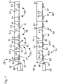
- the actuator arrangement 24 comprises a drive train formed by a plurality of straight drive shafts 62, which are aligned substantially along the spanwise direction.
- the drive unit 58 may be fixed in place and be connected to a first actuator 64 using an initial drive shaft 66 and universal joints 68.
- Splines 70 may be used to transfer the torque.
- the actuator assembly 38 comprises a second actuator 72 which is associated with the same high-lift device 20 as the first actuator 64.
- the first actuator 64 and the second actuator 72 thereby form an actuator group 74, which is associated with the same high-lift device 20.
- a connecting drive shaft 76 is mechanically coupled to the output shaft 56 of the first actuator 64 and to the input shaft 54 of the second actuator 72.
- the output shaft 56 of the second actuator 72 is connected to a further actuator group 78 via a further drive shaft 80.
- the actuator 40 is arranged in its entirety within the inner cavity 48, when in the fully retracted position, whereas the actuator 40 predominately protrudes outside the inner cavity 48 at the bottom in the fully extended position.
- the actuator 40 thus extends through one of the D-nose cut-outs 50.
- the drive unit 58 comprises an electric motor 82.
- each electric motor 82 is arranged on the axis defined by the actuator 40.
- each actuator 40 has its own electric motor 82.
- the movement of the actuator or the actuator arrangement 24 is substantially the same as the movement in the previous embodiment.
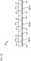
- FIG. 10 a variant of the previous actuator arrangement 24 ( Fig. 8 ) is depicted.
- an actuator group 74 are driven by a single electric motor 82, which is connected to the respective actuators 40 using a drive shaft 62.
- each actuator 40 is driven by the drive unit 58 individually.
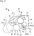
- the actuator 40 in the fully retracted position, is arranged in its entirety within the inner cavity 48, as well as the drive unit 58.
- the actuator 40 is arranged in an upper half of the inner cavity 48, whereas the drive unit 58 is arranged in a lower half of the inner cavity 48, when in the fully retracted position.
- the actuator 40 In the fully extended position, the actuator 40 is predominately protruding outside of the fixed leading edge member 26, whereas the drive unit 58 is still predominately accommodated within the inner cavity 48.
- both the actuator 40 and the drive unit 58 are arranged in an upper half of the inner cavity 48 in the fully retracted position, whereas in the fully extended position, the actuator 40 protrudes outside the inner cavity 48 and the drive unit 58 is entirely accommodated within the inner cavity 48.
- the actuators 40 such as geared rotary actuators 42, can be integrated more easily into the small space provided by fixed leading edge member 26 and the high-lift device 20.
- the stroke of the actuator 40 may be maximized which allows an increase in efficiency due to a reduction of required forces for moving the high-lift device 20. Due to the lower requirements the overall size of actuators 40 may be reduced so that weight and space efficiency are improved. Furthermore, the size of the D-nose cut-out 50 may be reduced using a preferred actuator arrangement 24.
- an actuator arrangement (24) for a fixed leading edge member (26) is proposed.
- the fixed leading edge member (26) has an inner cavity (48) defined by the outer skin (44) and ribs (46).
- the actuator arrangement (24) comprises at least one geared rotary actuator (42) which moves relative to the other parts along a circular arc section (52) during extending and retracting of the high-lift device (20) between a fully retracted position and a fully extended position.
- the geared rotary actuator (42) In the fully retracted position, the geared rotary actuator (42) is predominantly accommodated within the inner cavity (48) and in the extended position the geared rotary actuator (42) is predominantly positioned outside the inner cavity (48), preferably protruding through a D-nose cut-out (50).
Landscapes
- Engineering & Computer Science (AREA)
- Aviation & Aerospace Engineering (AREA)
- Mechanical Engineering (AREA)
- Automation & Control Theory (AREA)
- Actuator (AREA)
- Transmission Devices (AREA)
Claims (15)
- Flügelanordnung (18) für ein Luftfahrzeug (10), wobei die Flügelanordnung (18) ein festes Vorderkantenelement (26), eine Hochauftriebsvorrichtung (20), die beweglich an dem festen Vorderkantenelement (26) angebracht ist, und eine Aktuatoranordnung (24) umfasst, wobei die Aktuatoranordnung (24) Folgendes umfasst:- einen festen Vorderkantenhebel (34), der an einem Montagepunkt (53) am festen Vorderkantenelement (26) befestigt ist,- einen Hochauftriebsvorrichtungshebel (36), der an der Hochauftriebsvorrichtung (20) befestigt ist, und- eine Aktuatoranordnung (38), die zum Antreiben des festen Vorderkantenhebels (34) und des Hochauftriebsvorrichtungshebels (36) relativ zueinander ausgelegt ist,um Folgendes zu ermöglicheneine Bewegung der Hochauftriebsvorrichtung (20) zwischen einer vollständig eingefahrenen Position und einer vollständig ausgefahrenen Position, wobei das feste Vorderkantenelement (26) einen inneren Hohlraum (48) aufweist, der zumindest teilweise durch eine Außenhaut (44) und eine Rippe (46) definiert ist, wobei die Aktuatoranordnung (24) zum Ein- und Ausfahren der Hochauftriebsvorrichtung (20) ausgelegt ist,wobei die Aktuatoranordnung (38) mindestens einen verzahnten Drehaktuator (42) beinhaltet, wobei die Aktuatoranordnung (38) so ausgelegt ist, dass der verzahnte Drehaktuator (42) während eines Ausfahrens und Einfahrens der Hochauftriebsvorrichtung (20) zwischen einer vollständig eingefahrenen Position, in der der verzahnte Drehaktuator (42) überwiegend innerhalb des inneren Hohlraums (48) aufgenommen ist, und einer vollständig ausgefahrenen Position, in der der verzahnte Drehaktuator (42) überwiegend außerhalb des inneren Hohlraums (48) positioniert ist, bewegbar ist, wobei der verzahnte Drehaktuator (42) um eine Drehachse drehbar ist, die durch den Montagepunkt (53) des festen Vorderkantenhebels (34) definiert ist.
- Flügelanordnung (18) nach einem der vorhergehenden Ansprüche, wobei der verzahnte Drehaktuator (42) entlang eines Kreisbogenabschnitts (52) in einer Vorwärtsrichtung während eines Ausfahrens der Hochauftriebsvorrichtung (20) und/oder in einer Rückwärtsrichtung während eines Einfahrens der Hochauftriebsvorrichtung (20) bewegbar ist.
- Flügelanordnung (18) nach einem der vorhergehenden Ansprüche, wobei der verzahnte Drehaktuator (42), wenn er sich in der vollständig eingefahrenen Position befindet, vollständig innerhalb des inneren Hohlraums (48) aufgenommen ist.
- Flügelanordnung (18) nach einem der vorhergehenden Ansprüche, wobei der verzahnte Drehaktuator (42), wenn er sich in der vollständig ausgefahrenen Position befindet, vollständig außerhalb des inneren Hohlraums (48) positioniert ist.
- Flügelanordnung (18) nach einem der vorhergehenden Ansprüche, wobei die Aktuatoranordnung (38) mindestens zwei Aktuatoren beinhaltet und jeweils zwei Aktuatoren in eine jeweilige Aktuatorgruppe (74) zum Antreiben einer Hochauftriebsvorrichtung (20) zusammengefasst sind.
- Flügelanordnung (18) nach einem der vorhergehenden Ansprüche, ferner umfassend eine Antriebseinheit (58), die mechanische Leistung zum Antreiben der Aktuatoranordnung (38) bereitstellt, wobei die Aktuatoranordnung (38) einen spannweitigen Antriebsstrang (60) mit mindestens einer spannweitigen geraden Antriebswelle (62) beinhaltet, die zwei angrenzende Aktuatoren (40) mechanisch koppelt.
- Flügelanordnung (18) nach Anspruch 6, wobei die Aktuatoranordnung (38) einen ersten Aktuator (64) und einen zweiten Aktuator (72) beinhaltet, wobei der erste Aktuator (64) mechanisch mit der Antriebseinheit (58) gekoppelt ist.
- Flügelanordnung (18) nach Anspruch 7, wobei der erste Aktuator (64) über eine schwenkbare Antriebswelle (62) mechanisch mit der Antriebseinheit (58) gekoppelt ist.
- Flügelanordnung (18) nach Anspruch 7 oder 8, wobei der zweite Aktuator (72) über eine spannweitige gerade Antriebswelle (62) mechanisch mit dem ersten Aktuator (64) gekoppelt ist.
- Flügelanordnung (18) nach einem der vorhergehenden Ansprüche, ferner umfassend eine oder die Antriebseinheit (58), die mechanische Leistung zum Antreiben der Aktuatoranordnung (38) bereitstellt, wobei die Antriebseinheit (58) spannweitig zwischen angrenzenden Aktuatoren (40) angeordnet ist, die mit einer Hochauftriebsvorrichtung (20) assoziiert sind.
- Flügelanordnung (18) nach einem der vorhergehenden Ansprüche, ferner umfassend eine oder die Antriebseinheit (58), die mechanische Leistung zum Antreiben der Aktuatoranordnung (38) bereitstellt, wobei die Antriebseinheit (58) auf der gleichen Achse wie der verzahnte Drehaktuator (42) in einer Spannweitenrichtung angeordnet ist.
- Flügelanordnung (18) nach einem der vorhergehenden Ansprüche, ferner umfassend eine oder die Antriebseinheit (58), die mechanische Leistung zum Antreiben der Aktuatoranordnung (38) bereitstellt, wobei die Antriebseinheit (58) hinter dem verzahnten Drehaktuator (42) angeordnet ist.
- Flügelanordnung (18) nach einem der vorhergehenden Ansprüche, ferner umfassend eine oder die Antriebseinheit (58), die mechanische Leistung zum Antreiben der Aktuatoranordnung (38) bereitstellt, wobei die Antriebseinheit (58) angrenzend an den verzahnten Drehaktuator (42) in einer Spannweitenrichtung oder einer Sehnenrichtung angeordnet ist.
- Flügelanordnung (18) nach einem der vorhergehenden Ansprüche, ferner umfassend eine oder die Antriebseinheit (58), die mechanische Leistung zum Antreiben der Aktuatoranordnung (38) bereitstellt, wobei die Antriebseinheit (58) an der Aktuatoranordnung (38) angebracht ist, um gleichzeitig bewegbar zu sein.
- Luftfahrzeug (10), das eine Flügelanordnung (18) nach einem der vorhergehenden Ansprüche umfasst.
Applications Claiming Priority (2)
| Application Number | Priority Date | Filing Date | Title |
|---|---|---|---|
| DE102019124987 | 2019-09-17 | ||
| PCT/EP2020/075643 WO2021052908A1 (en) | 2019-09-17 | 2020-09-14 | Actuator arrangement for a fixed leading edge member of an aircraft, wing assembly and aircraft equipped with said actuator arrangement |
Publications (2)
| Publication Number | Publication Date |
|---|---|
| EP3962810A1 EP3962810A1 (de) | 2022-03-09 |
| EP3962810B1 true EP3962810B1 (de) | 2025-03-12 |
Family
ID=72474334
Family Applications (1)
| Application Number | Title | Priority Date | Filing Date |
|---|---|---|---|
| EP20771850.3A Active EP3962810B1 (de) | 2019-09-17 | 2020-09-14 | Aktuatoranordnung für ein festes eintrittskantelement einer flugzeugflügelanordnung und flugzeug mit dieser betätigungsvorrichtung |
Country Status (4)
| Country | Link |
|---|---|
| US (1) | US11866155B2 (de) |
| EP (1) | EP3962810B1 (de) |
| CN (1) | CN114174169A (de) |
| WO (1) | WO2021052908A1 (de) |
Families Citing this family (2)
| Publication number | Priority date | Publication date | Assignee | Title |
|---|---|---|---|---|
| EP4086165B1 (de) * | 2021-05-03 | 2024-08-28 | Airbus Operations GmbH | Flügel für ein flugzeug |
| US12116108B2 (en) * | 2021-12-16 | 2024-10-15 | Hamilton Sundstrand Corporation | Aircraft control surface actuation mechanism |
Citations (1)
| Publication number | Priority date | Publication date | Assignee | Title |
|---|---|---|---|---|
| US3617018A (en) * | 1970-01-26 | 1971-11-02 | Boeing Co | Folding flap |
Family Cites Families (15)
| Publication number | Priority date | Publication date | Assignee | Title |
|---|---|---|---|---|
| US3128966A (en) | 1964-04-14 | Alvarez-calderon | ||
| US3640150A (en) | 1970-06-25 | 1972-02-08 | Curtiss Wright Corp | Power driven actuator of the compound planetary gear type |
| US4979700A (en) | 1988-10-28 | 1990-12-25 | Curtiss Wright Flight Systems, Inc. | Rotary actuator for leading edge flap of aircraft |
| JP3565811B2 (ja) | 2001-10-09 | 2004-09-15 | ティーエスコーポレーション株式会社 | 操舵翼の制御装置 |
| EP1338506A1 (de) | 2002-02-15 | 2003-08-27 | Fairchild Dornier GmbH | Flugzeugflügel mit Spalt- und Krüger-Klappen |
| GB0906270D0 (en) * | 2009-04-14 | 2009-05-20 | Ge Aviat Systems Ltd | High lift devices for aircraft |
| FR2946617B1 (fr) * | 2009-06-10 | 2012-11-16 | Sagem Defense Securite | Dispositif d'actionnement d'une gouverne d'aeronef. |
| DE102011105912A1 (de) * | 2011-06-28 | 2013-01-03 | Airbus Operations Gmbh | Tragflügel mit einem Hauptflügel und einem Hochauftriebskörper sowie Verfahren zur Ausführung von Verstellbewegungen eines Hochauftriebskörpers gegenüber einem Hauptflügel |
| US10759515B2 (en) | 2014-09-10 | 2020-09-01 | Hamilton Sunstrand Corporation | Electromechanical hinge-line rotary actuator |
| FR3028836B1 (fr) | 2014-11-20 | 2016-12-16 | Sagem Defense Securite | Actionneur de gouverne de commande de vol d'un aeronef |
| US10633080B2 (en) | 2016-07-22 | 2020-04-28 | The Boeing Company | Electronically controlled rotary actuator for an aircraft control surface |
| EP3378760A1 (de) * | 2017-03-24 | 2018-09-26 | Airbus Operations GmbH | Flugzeugflügel |
| EP3378762A1 (de) | 2017-03-24 | 2018-09-26 | Airbus Operations GmbH | Flügel für ein flugzeug |
| EP3501978B1 (de) * | 2017-12-21 | 2021-03-10 | Airbus Operations GmbH | Flügel für ein flugzeug |
| EP4063257B1 (de) * | 2021-03-23 | 2024-11-27 | Airbus Operations GmbH | Flügel für ein flugzeug |
-
2020
- 2020-09-14 WO PCT/EP2020/075643 patent/WO2021052908A1/en not_active Ceased
- 2020-09-14 EP EP20771850.3A patent/EP3962810B1/de active Active
- 2020-09-14 CN CN202080054153.8A patent/CN114174169A/zh active Pending
- 2020-09-14 US US17/615,069 patent/US11866155B2/en active Active
Patent Citations (1)
| Publication number | Priority date | Publication date | Assignee | Title |
|---|---|---|---|---|
| US3617018A (en) * | 1970-01-26 | 1971-11-02 | Boeing Co | Folding flap |
Also Published As
| Publication number | Publication date |
|---|---|
| WO2021052908A1 (en) | 2021-03-25 |
| CN114174169A (zh) | 2022-03-11 |
| US20220219808A1 (en) | 2022-07-14 |
| EP3962810A1 (de) | 2022-03-09 |
| US11866155B2 (en) | 2024-01-09 |
Similar Documents
| Publication | Publication Date | Title |
|---|---|---|
| EP2440453B1 (de) | Vorrichtung zur betätigung einer steuerfläche eines flugzeuges | |
| US7309043B2 (en) | Actuation device positioning systems and associated methods, including aircraft spoiler droop systems | |
| CN104039647B (zh) | 具有主翼和增升体的机翼及实现调节增升体相对于主翼的运动的方法 | |
| CN109789920B (zh) | 对飞行器上的多功能后缘操纵面进行驱动和引导的系统 | |
| EP1316501B1 (de) | Betätigungssystem für ein aerodynamisches Ruder | |
| US20070102587A1 (en) | Wing leading edge slat system | |
| EP4324737B1 (de) | Tragflügel | |
| EP3461738B1 (de) | Fowler-klappenbetätigungsvorrichtung und zugehörige verfahren | |
| US11104423B2 (en) | Wing for an aircraft | |
| US20120138738A1 (en) | System for increasing controllability for an aircraft | |
| EP3439952A1 (de) | Aktuator für adaptive schaufel | |
| US11866155B2 (en) | Actuator arrangement for a fixed leading edge member of an aircraft, wing assembly and aircraft equipped with said actuator arrangement | |
| EP1868888B1 (de) | Antriebssystem für landeklappe | |
| EP4311766B1 (de) | Flügel für ein flugzeug | |
| US12208895B2 (en) | Wing for an aircraft | |
| EP4086166B1 (de) | Flügel für ein flugzeug | |
| EP2746151B1 (de) | Klappensystem für ein Flugzeug, Verfahren zur Einstellung des Auftriebs eines Flugzeugs und Flugzeug mit einem Hauptflügel und mindestens einem Klappensystem | |
| EP4656514A1 (de) | Flugzeugtragfläche | |
| EP4733188A1 (de) | Antriebsanordnung zum antreiben einer beweglichen strömungsvorrichtung eines flugzeugs | |
| US12612152B2 (en) | Wing for an aircraft | |
| EP4470912B1 (de) | Aerodynamisches system für ein flugzeug | |
| EP4286272B1 (de) | Aktuatoranordnung und flügelanordnung für ein flugzeug | |
| EP4660074A1 (de) | Flügel für ein flugzeug | |
| US20260109449A1 (en) | Support assembly for a high lift body, high lift body arrangement, as well as wing and aircraft comprising same | |
| HK40109059A (en) | An aerofoil |
Legal Events
| Date | Code | Title | Description |
|---|---|---|---|
| STAA | Information on the status of an ep patent application or granted ep patent |
Free format text: STATUS: UNKNOWN |
|
| STAA | Information on the status of an ep patent application or granted ep patent |
Free format text: STATUS: THE INTERNATIONAL PUBLICATION HAS BEEN MADE |
|
| PUAI | Public reference made under article 153(3) epc to a published international application that has entered the european phase |
Free format text: ORIGINAL CODE: 0009012 |
|
| STAA | Information on the status of an ep patent application or granted ep patent |
Free format text: STATUS: REQUEST FOR EXAMINATION WAS MADE |
|
| 17P | Request for examination filed |
Effective date: 20211201 |
|
| AK | Designated contracting states |
Kind code of ref document: A1 Designated state(s): AL AT BE BG CH CY CZ DE DK EE ES FI FR GB GR HR HU IE IS IT LI LT LU LV MC MK MT NL NO PL PT RO RS SE SI SK SM TR |
|
| DAV | Request for validation of the european patent (deleted) | ||
| DAX | Request for extension of the european patent (deleted) | ||
| STAA | Information on the status of an ep patent application or granted ep patent |
Free format text: STATUS: EXAMINATION IS IN PROGRESS |
|
| 17Q | First examination report despatched |
Effective date: 20230718 |
|
| GRAP | Despatch of communication of intention to grant a patent |
Free format text: ORIGINAL CODE: EPIDOSNIGR1 |
|
| STAA | Information on the status of an ep patent application or granted ep patent |
Free format text: STATUS: GRANT OF PATENT IS INTENDED |
|
| INTG | Intention to grant announced |
Effective date: 20241017 |
|
| GRAS | Grant fee paid |
Free format text: ORIGINAL CODE: EPIDOSNIGR3 |
|
| GRAA | (expected) grant |
Free format text: ORIGINAL CODE: 0009210 |
|
| STAA | Information on the status of an ep patent application or granted ep patent |
Free format text: STATUS: THE PATENT HAS BEEN GRANTED |
|
| AK | Designated contracting states |
Kind code of ref document: B1 Designated state(s): AL AT BE BG CH CY CZ DE DK EE ES FI FR GB GR HR HU IE IS IT LI LT LU LV MC MK MT NL NO PL PT RO RS SE SI SK SM TR |
|
| REG | Reference to a national code |
Ref country code: GB Ref legal event code: FG4D |
|
| REG | Reference to a national code |
Ref country code: CH Ref legal event code: EP |
|
| REG | Reference to a national code |
Ref country code: DE Ref legal event code: R096 Ref document number: 602020047617 Country of ref document: DE |
|
| REG | Reference to a national code |
Ref country code: IE Ref legal event code: FG4D |
|
| PG25 | Lapsed in a contracting state [announced via postgrant information from national office to epo] |
Ref country code: RS Free format text: LAPSE BECAUSE OF FAILURE TO SUBMIT A TRANSLATION OF THE DESCRIPTION OR TO PAY THE FEE WITHIN THE PRESCRIBED TIME-LIMIT Effective date: 20250612 |
|
| PG25 | Lapsed in a contracting state [announced via postgrant information from national office to epo] |
Ref country code: FI Free format text: LAPSE BECAUSE OF FAILURE TO SUBMIT A TRANSLATION OF THE DESCRIPTION OR TO PAY THE FEE WITHIN THE PRESCRIBED TIME-LIMIT Effective date: 20250312 |
|
| PG25 | Lapsed in a contracting state [announced via postgrant information from national office to epo] |
Ref country code: ES Free format text: LAPSE BECAUSE OF FAILURE TO SUBMIT A TRANSLATION OF THE DESCRIPTION OR TO PAY THE FEE WITHIN THE PRESCRIBED TIME-LIMIT Effective date: 20250312 |
|
| REG | Reference to a national code |
Ref country code: LT Ref legal event code: MG9D |
|
| PG25 | Lapsed in a contracting state [announced via postgrant information from national office to epo] |
Ref country code: NO Free format text: LAPSE BECAUSE OF FAILURE TO SUBMIT A TRANSLATION OF THE DESCRIPTION OR TO PAY THE FEE WITHIN THE PRESCRIBED TIME-LIMIT Effective date: 20250612 |
|
| PG25 | Lapsed in a contracting state [announced via postgrant information from national office to epo] |
Ref country code: HR Free format text: LAPSE BECAUSE OF FAILURE TO SUBMIT A TRANSLATION OF THE DESCRIPTION OR TO PAY THE FEE WITHIN THE PRESCRIBED TIME-LIMIT Effective date: 20250312 |
|
| REG | Reference to a national code |
Ref country code: NL Ref legal event code: MP Effective date: 20250312 |
|
| PG25 | Lapsed in a contracting state [announced via postgrant information from national office to epo] |
Ref country code: LV Free format text: LAPSE BECAUSE OF FAILURE TO SUBMIT A TRANSLATION OF THE DESCRIPTION OR TO PAY THE FEE WITHIN THE PRESCRIBED TIME-LIMIT Effective date: 20250312 |
|
| PG25 | Lapsed in a contracting state [announced via postgrant information from national office to epo] |
Ref country code: GR Free format text: LAPSE BECAUSE OF FAILURE TO SUBMIT A TRANSLATION OF THE DESCRIPTION OR TO PAY THE FEE WITHIN THE PRESCRIBED TIME-LIMIT Effective date: 20250613 Ref country code: BG Free format text: LAPSE BECAUSE OF FAILURE TO SUBMIT A TRANSLATION OF THE DESCRIPTION OR TO PAY THE FEE WITHIN THE PRESCRIBED TIME-LIMIT Effective date: 20250312 |
|
| REG | Reference to a national code |
Ref country code: AT Ref legal event code: MK05 Ref document number: 1774839 Country of ref document: AT Kind code of ref document: T Effective date: 20250312 |
|
| PG25 | Lapsed in a contracting state [announced via postgrant information from national office to epo] |
Ref country code: NL Free format text: LAPSE BECAUSE OF FAILURE TO SUBMIT A TRANSLATION OF THE DESCRIPTION OR TO PAY THE FEE WITHIN THE PRESCRIBED TIME-LIMIT Effective date: 20250312 |
|
| PG25 | Lapsed in a contracting state [announced via postgrant information from national office to epo] |
Ref country code: SE Free format text: LAPSE BECAUSE OF FAILURE TO SUBMIT A TRANSLATION OF THE DESCRIPTION OR TO PAY THE FEE WITHIN THE PRESCRIBED TIME-LIMIT Effective date: 20250312 |
|
| PG25 | Lapsed in a contracting state [announced via postgrant information from national office to epo] |
Ref country code: SM Free format text: LAPSE BECAUSE OF FAILURE TO SUBMIT A TRANSLATION OF THE DESCRIPTION OR TO PAY THE FEE WITHIN THE PRESCRIBED TIME-LIMIT Effective date: 20250312 |
|
| PG25 | Lapsed in a contracting state [announced via postgrant information from national office to epo] |
Ref country code: PT Free format text: LAPSE BECAUSE OF FAILURE TO SUBMIT A TRANSLATION OF THE DESCRIPTION OR TO PAY THE FEE WITHIN THE PRESCRIBED TIME-LIMIT Effective date: 20250714 |
|
| PGFP | Annual fee paid to national office [announced via postgrant information from national office to epo] |
Ref country code: DE Payment date: 20250919 Year of fee payment: 6 |
|
| PG25 | Lapsed in a contracting state [announced via postgrant information from national office to epo] |
Ref country code: PL Free format text: LAPSE BECAUSE OF FAILURE TO SUBMIT A TRANSLATION OF THE DESCRIPTION OR TO PAY THE FEE WITHIN THE PRESCRIBED TIME-LIMIT Effective date: 20250312 Ref country code: IT Free format text: LAPSE BECAUSE OF FAILURE TO SUBMIT A TRANSLATION OF THE DESCRIPTION OR TO PAY THE FEE WITHIN THE PRESCRIBED TIME-LIMIT Effective date: 20250312 |
|
| PGFP | Annual fee paid to national office [announced via postgrant information from national office to epo] |
Ref country code: BE Payment date: 20250918 Year of fee payment: 6 Ref country code: GB Payment date: 20250919 Year of fee payment: 6 |
|
| PG25 | Lapsed in a contracting state [announced via postgrant information from national office to epo] |
Ref country code: AT Free format text: LAPSE BECAUSE OF FAILURE TO SUBMIT A TRANSLATION OF THE DESCRIPTION OR TO PAY THE FEE WITHIN THE PRESCRIBED TIME-LIMIT Effective date: 20250312 |
|
| PGFP | Annual fee paid to national office [announced via postgrant information from national office to epo] |
Ref country code: FR Payment date: 20250922 Year of fee payment: 6 |
|
| PG25 | Lapsed in a contracting state [announced via postgrant information from national office to epo] |
Ref country code: EE Free format text: LAPSE BECAUSE OF FAILURE TO SUBMIT A TRANSLATION OF THE DESCRIPTION OR TO PAY THE FEE WITHIN THE PRESCRIBED TIME-LIMIT Effective date: 20250312 Ref country code: CZ Free format text: LAPSE BECAUSE OF FAILURE TO SUBMIT A TRANSLATION OF THE DESCRIPTION OR TO PAY THE FEE WITHIN THE PRESCRIBED TIME-LIMIT Effective date: 20250312 |
|
| PG25 | Lapsed in a contracting state [announced via postgrant information from national office to epo] |
Ref country code: RO Free format text: LAPSE BECAUSE OF FAILURE TO SUBMIT A TRANSLATION OF THE DESCRIPTION OR TO PAY THE FEE WITHIN THE PRESCRIBED TIME-LIMIT Effective date: 20250312 |
|
| PG25 | Lapsed in a contracting state [announced via postgrant information from national office to epo] |
Ref country code: SK Free format text: LAPSE BECAUSE OF FAILURE TO SUBMIT A TRANSLATION OF THE DESCRIPTION OR TO PAY THE FEE WITHIN THE PRESCRIBED TIME-LIMIT Effective date: 20250312 |
|
| PG25 | Lapsed in a contracting state [announced via postgrant information from national office to epo] |
Ref country code: IS Free format text: LAPSE BECAUSE OF FAILURE TO SUBMIT A TRANSLATION OF THE DESCRIPTION OR TO PAY THE FEE WITHIN THE PRESCRIBED TIME-LIMIT Effective date: 20250712 |
|
| REG | Reference to a national code |
Ref country code: DE Ref legal event code: R097 Ref document number: 602020047617 Country of ref document: DE |
|
| PG25 | Lapsed in a contracting state [announced via postgrant information from national office to epo] |
Ref country code: DK Free format text: LAPSE BECAUSE OF FAILURE TO SUBMIT A TRANSLATION OF THE DESCRIPTION OR TO PAY THE FEE WITHIN THE PRESCRIBED TIME-LIMIT Effective date: 20250312 |
|
| PLBE | No opposition filed within time limit |
Free format text: ORIGINAL CODE: 0009261 |
|
| STAA | Information on the status of an ep patent application or granted ep patent |
Free format text: STATUS: NO OPPOSITION FILED WITHIN TIME LIMIT |
|
| REG | Reference to a national code |
Ref country code: CH Ref legal event code: L10 Free format text: ST27 STATUS EVENT CODE: U-0-0-L10-L00 (AS PROVIDED BY THE NATIONAL OFFICE) Effective date: 20260121 |
|
| 26N | No opposition filed |
Effective date: 20251215 |
|
| REG | Reference to a national code |
Ref country code: CH Ref legal event code: H13 Free format text: ST27 STATUS EVENT CODE: U-0-0-H10-H13 (AS PROVIDED BY THE NATIONAL OFFICE) Effective date: 20260504 |