EP3961832A1 - Fault-point-locating device - Google Patents
Fault-point-locating device Download PDFInfo
- Publication number
- EP3961832A1 EP3961832A1 EP19926470.6A EP19926470A EP3961832A1 EP 3961832 A1 EP3961832 A1 EP 3961832A1 EP 19926470 A EP19926470 A EP 19926470A EP 3961832 A1 EP3961832 A1 EP 3961832A1
- Authority
- EP
- European Patent Office
- Prior art keywords
- tank
- fault
- point
- breaker
- current
- Prior art date
- Legal status (The legal status is an assumption and is not a legal conclusion. Google has not performed a legal analysis and makes no representation as to the accuracy of the status listed.)
- Granted
Links
Images



Classifications
-
- H—ELECTRICITY
- H02—GENERATION; CONVERSION OR DISTRIBUTION OF ELECTRIC POWER
- H02B—BOARDS, SUBSTATIONS OR SWITCHING ARRANGEMENTS FOR THE SUPPLY OR DISTRIBUTION OF ELECTRIC POWER
- H02B13/00—Arrangement of switchgear in which switches are enclosed in, or structurally associated with, a casing, e.g. cubicle
- H02B13/02—Arrangement of switchgear in which switches are enclosed in, or structurally associated with, a casing, e.g. cubicle with metal casing
- H02B13/035—Gas-insulated switchgear
- H02B13/065—Means for detecting or reacting to mechanical or electrical defects
-
- G—PHYSICS
- G01—MEASURING; TESTING
- G01R—MEASURING ELECTRIC VARIABLES; MEASURING MAGNETIC VARIABLES
- G01R31/00—Arrangements for testing electric properties; Arrangements for locating electric faults; Arrangements for electrical testing characterised by what is being tested not provided for elsewhere
- G01R31/327—Testing of circuit interrupters, switches or circuit-breakers
- G01R31/3271—Testing of circuit interrupters, switches or circuit-breakers of high voltage or medium voltage devices
- G01R31/3272—Apparatus, systems or circuits therefor
-
- G—PHYSICS
- G01—MEASURING; TESTING
- G01R—MEASURING ELECTRIC VARIABLES; MEASURING MAGNETIC VARIABLES
- G01R31/00—Arrangements for testing electric properties; Arrangements for locating electric faults; Arrangements for electrical testing characterised by what is being tested not provided for elsewhere
- G01R31/327—Testing of circuit interrupters, switches or circuit-breakers
- G01R31/3271—Testing of circuit interrupters, switches or circuit-breakers of high voltage or medium voltage devices
- G01R31/3275—Fault detection or status indication
-
- H—ELECTRICITY
- H02—GENERATION; CONVERSION OR DISTRIBUTION OF ELECTRIC POWER
- H02B—BOARDS, SUBSTATIONS OR SWITCHING ARRANGEMENTS FOR THE SUPPLY OR DISTRIBUTION OF ELECTRIC POWER
- H02B3/00—Apparatus specially adapted for the manufacture, assembly, or maintenance of boards or switchgear
-
- G—PHYSICS
- G01—MEASURING; TESTING
- G01R—MEASURING ELECTRIC VARIABLES; MEASURING MAGNETIC VARIABLES
- G01R31/00—Arrangements for testing electric properties; Arrangements for locating electric faults; Arrangements for electrical testing characterised by what is being tested not provided for elsewhere
- G01R31/12—Testing dielectric strength or breakdown voltage ; Testing or monitoring effectiveness or level of insulation, e.g. of a cable or of an apparatus, for example using partial discharge measurements; Electrostatic testing
- G01R31/1227—Testing dielectric strength or breakdown voltage ; Testing or monitoring effectiveness or level of insulation, e.g. of a cable or of an apparatus, for example using partial discharge measurements; Electrostatic testing of components, parts or materials
- G01R31/1254—Testing dielectric strength or breakdown voltage ; Testing or monitoring effectiveness or level of insulation, e.g. of a cable or of an apparatus, for example using partial discharge measurements; Electrostatic testing of components, parts or materials of gas-insulated power appliances or vacuum gaps
-
- G—PHYSICS
- G01—MEASURING; TESTING
- G01R—MEASURING ELECTRIC VARIABLES; MEASURING MAGNETIC VARIABLES
- G01R31/00—Arrangements for testing electric properties; Arrangements for locating electric faults; Arrangements for electrical testing characterised by what is being tested not provided for elsewhere
- G01R31/12—Testing dielectric strength or breakdown voltage ; Testing or monitoring effectiveness or level of insulation, e.g. of a cable or of an apparatus, for example using partial discharge measurements; Electrostatic testing
- G01R31/14—Circuits therefor, e.g. for generating test voltages, sensing circuits
-
- H—ELECTRICITY
- H02—GENERATION; CONVERSION OR DISTRIBUTION OF ELECTRIC POWER
- H02B—BOARDS, SUBSTATIONS OR SWITCHING ARRANGEMENTS FOR THE SUPPLY OR DISTRIBUTION OF ELECTRIC POWER
- H02B13/00—Arrangement of switchgear in which switches are enclosed in, or structurally associated with, a casing, e.g. cubicle
- H02B13/02—Arrangement of switchgear in which switches are enclosed in, or structurally associated with, a casing, e.g. cubicle with metal casing
- H02B13/035—Gas-insulated switchgear
- H02B13/075—Earthing arrangements
Definitions
- the present invention relates to a fault-point-locating device that locates a fault point in a three-phase separating gas-insulated switchgear.
- a conventional fault-point-locating device monitors the pressure in each tank equivalent to a gas section, and detects an increase in the pressure caused by a ground fault or a short circuit, so as to locate a fault point where the ground fault or the short circuit has occurred.
- the pressure in the tank can also be increased due to an arc generated during current interruption other than the ground fault or the short circuit.
- the fault-point-locating device is thus required to be capable of distinguishing a short circuit in the breaker tank from current interruption by a breaker.
- Patent Literature 1 discloses a fault-point-locating device provided with current transformers between a breaker tank and each of the tanks adjacent to the breaker tank, so as to monitor a ground fault in the breaker tank on the basis of the polarity of a current flowing through each of the current transformers.
- the current transformers are provided respectively between the breaker tank and a busbar tank, between the breaker tank and a cable head tank, and between the breaker tank and an earth.
- the present invention has been achieved to solve the above problems, and an object of the present invention is to provide a fault-point-locating device that makes it possible to reduce the number of constituent elements to be provided in a gas-insulated switchgear to locate a fault point in a tank in which a breaker is accommodated.
- a fault-point-locating device locates a fault point in a gas-insulated switchgear including a first tank having a breaker for a first phase accommodated therein, a second tank having a breaker for a second phase accommodated therein, and a third tank having a breaker for a third phase accommodated therein.
- the fault-point-locating device comprises a measurement unit to measure a waveform of a current flowing between the first tank and a grounding electrode, a waveform of a current flowing between the second tank and the grounding electrode, and a waveform of a current flowing between the third tank and the grounding electrode, the first tank, the second tank, and the third tank being connected to the grounding electrode, and a location processing unit to perform a process of locating the fault point in the first tank, the second tank, and the third tank on the basis of a measurement result of a waveform of each of the currents.
- the fault-point-locating device has an effect where it is possible to reduce the number of constituent elements to be provided in a gas-insulated switchgear to locate a fault point in a tank in which a breaker is accommodated.
- a fault-point-locating device according to embodiments of the present invention will be described in detail below with reference to the drawings.
- the present invention is not limited to the embodiments.
- FIG. 1 is a block diagram illustrating a configuration of a fault-point-locating device according to a first embodiment of the present invention.
- FIG. 2 is a diagram illustrating a schematic configuration of a gas-insulated switchgear that is a target for locating a fault point by the fault-point-locating device illustrated in FIG. 1 .
- a gas-insulated switchgear 10 illustrated in FIG. 2 is installed in power facilities such as a power plant or a substation.
- a voltage is applied to a busbar for three phases including a U-phase, a V-phase, and a W-phase. Wires for the three phases branch off from the busbar toward a target to/from which power is transmitted/received. Breakers are connected to branch wires that are the wires that branch off from the busbar. The busbar, the branch wires, and the breakers are accommodated respectively in tanks filled with insulating gas.
- the gas-insulated switchgear 10 is a so-called "three-phase separating gas-insulated switchgear" in which the branch wires for three phases are individually accommodated in separate tanks. In the three-phase separating gas-insulated switchgear, a ground fault may occur, while a phase-to-phase short circuit does not occur.
- the gas-insulated switchgear 10 includes a breaker tank 12a that is a first tank, a breaker tank 12b that is a second tank, and a breaker tank 12c that is a third tank.
- a breaker for a U-phase that is a first phase is accommodated in the breaker tank 12a.
- a breaker for a V-phase that is a second phase is accommodated in the breaker tank 12b.
- a breaker for a W-phase that is a third phase is accommodated in the breaker tank 12c.
- the busbar is accommodated in a busbar tank 11.
- Tanks other than the busbar tank 11 and the breaker tanks 12a, 12b, and 12c are connection tanks 13.
- a branch wire or a device connected to the branch wire is accommodated in each of the connection tanks 13.
- the busbar tank 11, the breaker tanks 12a, 12b, and 12c, and the connection tanks 13 illustrated in FIG. 1 form a single unit.
- a plurality of units are provided in the gas-insulated switchgear 10.
- the breaker tank 12a is installed on a stand 14a.
- the breaker tank 12b is installed on a stand 14b.
- the breaker tank 12c is installed on a stand 14c.
- the busbar tank 11 and the connection tanks 13 are installed on their respective stands similarly to the breaker tanks 12a, 12b, and 12c.
- FIG. 2 omits illustrations of the stand on which the busbar tank 11 is installed, and the stands on which the connection tanks 13 are installed.
- the stands 14a, 14b, and 14c are installed on a metal base 17.
- the stand 14a supports the breaker tank 12a on the metal base 17.
- the stand 14b supports the breaker tank 12b on the metal base 17.
- the stand 14c supports the breaker tank 12c on the metal base 17.
- the metal base 17 is provided in each unit.
- a grounding electrode 18 is connected to the metal base 17.
- the breaker tanks 12a, 12b, and 12c are connected to the grounding electrode 18 through the stands 14a, 14b, and 14c, respectively, and through the metal base 17.
- the grounding electrode 18 connects the metal base 17 to a grounding mesh 19.
- the grounding mesh 19 is provided underground in the power facilities.
- the grounding mesh 19 is made of copper wires laid into a net. The spacing between the copper wires is approximately 1 meter to 10 meters. Each of the copper wires has a cross-sectional area of approximately 100 mm 2 .
- the busbar tank 11, the breaker tanks 12a, 12b, and 12c, and the connection tanks 13 are provided respectively with pressure sensors 15.
- Each of the pressure sensors 15 detects the pressure in the tank.
- the pressure sensor 15 provided on the breaker tank 12a is referred to as "pressure sensor 15a”.
- the pressure sensor 15 provided on the breaker tank 12b is referred to as “pressure sensor 15b”.
- the pressure sensor 15 provided on the breaker tank 12c is referred to as "pressure sensor 15c" .
- CTs 16a, 16b, and 16c detect a current.
- the CT 16a is attached to one of the columns that form the stand 14a.
- the CT 16b is attached to one of the columns that form the stand 14b.
- the CT 16c is attached to one of the columns that form the stand 14c.
- the CT 16a, 16b, or 16c is a so-called "through-type current transformer”.
- a fault-point-locating device 1 illustrated in FIG. 1 locates a fault point in the gas-insulated switchgear 10.
- the fault-point-locating device 1 is installed along with the gas-insulated switchgear 10 in the power facilities.
- Each of the pressure sensors 15 provided in the gas-insulated switchgear 10 is connected to the fault-point-locating device 1 through a signal line.
- Each of the pressure sensors 15 outputs a pressure signal indicating the result of pressure detection to the fault-point-locating device 1.
- Each of the CTs 16a, 16b, and 16c provided in the gas-insulated switchgear 10 is connected to the fault-point-locating device 1 through a signal line.
- Each of the CTs 16a, 16b, and 16c outputs a current signal indicating the result of current detection to the fault-point-locating device 1.
- the fault-point-locating device 1 includes a computation unit 2 to perform various types of computational processing, a pressure-signal input unit 3 to which a pressure signal is input from each of the pressure sensors 15, a current-signal input unit 4 to which a current signal is input from each of the CTs 16a, 16b, and 16c, and a display unit 5 to display information.
- the computation unit 2 includes a determination unit 6 to determine whether a pressure increase has occurred in each of the tanks, a measurement unit 7 to measure a current waveform, and a location processing unit 8 to perform a process of locating a fault point.
- the determination unit 6 processes a pressure signal to determine whether a pressure increase has occurred.
- the measurement unit 7 processes a current signal to measure a current waveform.
- the display unit 5 displays the result of location of the fault point by the location processing unit 8.
- the determination unit 6 monitors whether a pressure increase has occurred in the busbar tank 11 and the connection tanks 13 on the basis of pressure signals from the pressure sensors 15 provided on the busbar tank 11 and the connection tanks 13. When the determination unit 6 determines that a pressure increase has occurred in any one of the busbar tank 11 and the connection tanks 13, the location processing unit 8 locates the tank in which a pressure increase is determined to have occurred as a fault point. As described above, when a ground fault has occurred in any of the busbar tank 11 and the connection tanks 13, the location processing unit 8 determines a fault point in the busbar tank 11 and the connection tanks 13 on the basis of the result of determination performed by the determination unit 6 regarding whether a pressure increase has occurred.
- the determination unit 6 monitors whether a pressure increase has occurred in the breaker tanks 12a, 12b, and 12c.
- the measurement unit 7 monitors whether the CTs 16a, 16b, and 16c have detected a current. That is, the measurement unit 7 monitors whether a current flows from the breaker tank 12a via the stand 14a to the grounding electrode 18, monitors whether a current flows from the breaker tank 12b via the stand 14b to the grounding electrode 18, and monitors whether a current flows from the breaker tank 12c via the stand 14c to the grounding electrode 18.
- the measurement unit 7 measures a waveform of the current detected by each CT.
- the location processing unit 8 locates the one breaker tank as a fault point. In the manner as described above, on the basis of the determination result of whether a pressure increase has occurred, and the measurement result of the waveform of the currents, the location processing unit 8 performs a process of locating a fault point in the breaker tank 12a, the breaker tank 12b, and the breaker tank 12c.
- a ground-fault current 25 that is a portion of the current having flowed between the branch wire and the breaker tank 12a, flows from the breaker tank 12a through the connection tank 13 and the busbar tank 11 to a transformer that is a power supply in the power facilities.
- a ground-fault current 21 that is a portion of the current having flowed between the branch wire and the breaker tank 12a, flows through the stand 14a to the metal base 17.
- the CT 16a detects the ground-fault current 21.
- the CT 16b detects the ground-fault current 22.
- the CT 16c detects the ground-fault current 23.
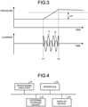
- FIG. 3 is a diagram for explaining a process to be performed by the location processing unit included in the fault-point-locating device illustrated in FIG. 1 .
- a graph illustrated on the upper side of FIG. 3 shows a relation between time and a pressure detected by the pressure sensor 15a.
- a graph illustrated on the lower side of FIG. 3 shows a relation between time and a current detected by the CTs 16a and 16b.
- a time T1 represents the time at which a ground fault has occurred at the position 28.
- the gas-insulated switchgear 10 causes respective breakers in the breaker tanks 12a, 12b, and 12c to perform an opening operation.
- a time T2 represents the time at which current interruption is completed by the opening operation of the breakers. The ground fault continues during the period from the time T1 to the time T2.
- the pressure detected by the pressure sensor 15a increases during the period from the time T1 to the time T2. At or after the time T2, the pressure gradually decreases due to heat dissipation from the breaker tank 12a.
- the determination unit 6 determines that a pressure increase has occurred.
- the threshold ⁇ P is set for each individual tank on the basis of the result of calculation of a minimum pressure increase at the occurrence of a ground fault. It is allowable that the threshold ⁇ P is set to a different value for each individual tank, or is set to a common value among all the tanks provided in the gas-insulated switchgear 10.
- the ground-fault currents 21, 22, 23, 24, 25, 26, and 27 are generated.
- the measurement unit 7 measures the current waveform of the ground-fault current 21 on the basis of a current signal from the CT 16a.
- the measurement unit 7 measures the current waveform of the ground-fault current 22 on the basis of a current signal from the CT 16b.
- the CT 16c detects the ground-fault current 23
- the measurement unit 7 measures the current waveform of the ground-fault current 23 on the basis of a current signal from the CT 16c.
- the graph on the lower side of FIG. 3 illustrates a current waveform I1 of the ground-fault current 21 and a current waveform I2 of the ground-fault current 22.
- the current waveform I1 and the current waveform I2 have opposite phases to each other. That is, the ground-fault current 21 is 180 degrees out of phase with the ground-fault current 22. Since the ground-fault current 23 and the ground-fault current 22 flow in the same direction, the current waveform of the ground-fault current 23 is in phase with the current waveform 12. That is, there is not phase shifting between the ground-fault current 23 and the ground-fault current 22. Therefore, only the current waveform I1, that is one of the three current waveforms obtained by measurement by the measurement unit 7, is out of phase with the other two current waveforms.
- the location processing unit 8 locates the breaker tank 12a as a fault point on the basis of the determination in the determination unit 6 that a pressure increase has occurred in the breaker tank 12a, and on the basis of the fact that only the current waveform I1 of the current waveforms measured by the measurement unit 7 is out of phase with the other current waveforms.
- the location processing unit 8 also locates the fault point in the same manner as performed on the breaker tank 12a.
- the location processing unit 8 can distinguish a short circuit having occurred in the breaker tanks 12a, 12b, and 12c from current interruption performed by the breaker due to reasons other than the ground fault.
- the path through which the ground-fault currents 25, 26, and 27 flow from the breaker tanks 12a, 12b, and 12c through the connection tanks 13 and the busbar tank 11 to the power supply has an impedance lower than the impedance on the path through which the ground-fault current 24 flows through the grounding electrode 18 and the grounding mesh 19 to the power supply.
- the grounding mesh 19 has an impedance per unit distance, where the value of impedance is of the order of magnitude of 1 ohm, and in contrast to that, the surface of the tank has an impedance per unit distance, where the value of impedance is of the order of magnitude of 10 milliohms.
- the value of impedance on the path passing through the surface of the tank is smaller by an order of magnitude than the value of impedance on the path passing through the grounding mesh 19. Accordingly, the paths of the ground-fault currents 25, 26, and 27 have a lower impedance than that on the path of the ground-fault current 24.
- ground-fault current 21 flows to the metal base 17, then due to the difference between the impedance values as described above, the ground-fault current 24 flows to the grounding electrode 18, and additionally the ground-fault currents 22 and 23 flow through the stands 14b and 14c to the breaker tanks 12b and 12c, respectively, and further the ground-fault currents 26 and 27 flow from the breaker tanks 12b and 12c, respectively, to the busbar tank 11.
- the ground-fault current 22 flowing through the stand 14b to the breaker tank 12b is generated, and the ground-fault current 23 flowing through the stand 14c to the breaker tank 12c is generated, making it possible for the CTs 16b and 16c to detect the ground-fault currents 22 and 23 whose current amount is sufficient for the measurement unit 7 to measure a current waveform.
- the fault-point-locating device 1 In the fault-point-locating device 1, three CTs 16a, 16b, and 16c are installed per unit, so that the fault-point-locating device 1 can monitor a ground fault in the breaker tanks 12a, 12b, and 12c.
- the fault-point-locating device 1 can locate a fault point by using a smaller number of CTs, that is, the CTs 16a, 16b, and 16c, as compared to a case where CTs are needed between the breaker tank 12a and each of its adjacent tanks, between the breaker tank 12b and each of its adjacent tanks, and between the breaker tank 12c and each of its adjacent tanks.
- the breaker tanks 12a, 12b, and 12c are not limited to being connected to the grounding electrode 18 through the metal base 17.
- the stands 14a, 14b, and 14c may not be necessarily installed on the metal base 17.
- the breaker tanks 12a, 12b, and 12c are grounded by connecting a grounding wire provided on each of the breaker tanks 12a, 12b, and 12c to the grounding mesh 19.
- the ground-fault current 21 having flowed from the stand 14a to the grounding mesh 19 partially flows through the grounding mesh 19 to the stand 14b and to the stand 14c. This can result in generating the ground-fault currents 22 and 23 similarly to the case when the metal base 17 is used.
- the function of the computation unit 2 included in the fault-point-locating device 1 is implemented by using a processing circuitry.
- the processing circuitry is dedicated hardware installed in the fault-point-locating device 1.
- the processing circuitry may be a processor that executes programs stored in a memory.
- FIG. 4 is a first diagram illustrating an example of the hardware configuration of the fault-point-locating device according to the first embodiment.
- FIG. 4 illustrates the hardware configuration of the fault-point-locating device 1 when the functions of the fault-point-locating device 1 are implemented by using the dedicated hardware.
- the fault-point-locating device 1 includes a processing circuitry 31 to perform various types of processing, an interface 32 through which the fault-point-locating device 1 is connected to external devices, an external storage device 33 to store therein various types of information, and a display device 34 that is an output device.
- the processing circuitry 31, the interface 32, the external storage device 33, and the display device 34 are connected to be capable of communicating with each other.
- the processing circuitry 31 as dedicated hardware is a single circuit, a combined circuit, a programmed processor, a parallel-programmed processor, an ASIC (Application Specific Integrated Circuit), an FPGA (Field-Programmable Gate Array), or a combination thereof.
- the functions of the determination unit 6, measurement unit 7, and the location processing unit 8 are implemented by using the processing circuitry 31.
- the functions of the pressure-signal input unit 3 and the current-signal input unit 4 are implemented by using the interface 32.
- the external storage device 33 stores therein the result of location by the location processing unit 8 and the threshold ⁇ P to be used for determination by the determination unit 6.
- the display device 34 displays the result of location and other information on a screen.
- the function of the display unit 5 is implemented by using the display device 34. It is allowable that the fault-point-locating device 1 includes an input device through which the threshold ⁇ P and other information is input.
- FIG. 5 is a second diagram illustrating an example of the hardware configuration of the fault-point-locating device according to the first embodiment.
- FIG. 5 illustrates the hardware configuration of the fault-point-locating device when the function of the computation unit 2 is implemented by using hardware that executes the programs.
- the fault-point-locating device 1 includes a processor 35, a memory 36, the interface 32, the external storage device 33, and the display device 34.
- the processor 35, the memory 36, the interface 32, the external storage device 33, and the display device 34 are connected to be capable of communicating with each other.
- the processor 35 is a CPU (Central Processing Unit), a processing device, a computation device, a microprocessor, a microcomputer, or a DSP (Digital Signal Processor). Each of the functions of the determination unit 6, the measurement unit 7, and the location processing unit 8 is implemented by the processor 35, software, firmware, or a combination of software and firmware.
- the software or firmware is described as a program to be stored in the memory 36 that is a built-in memory.
- the memory 36 is a nonvolatile or volatile semiconductor memory, and is a RAM (Random Access Memory), a ROM (Read Only Memory), a flash memory, an EPROM (Erasable Programmable Read Only Memory), or an EEPROM (registered trademark) (Electrically Erasable Programmable Read Only Memory).
- the fault-point-locating device 1 measures a waveform of a current flowing between the breaker tank 12a and the grounding electrode 18, a current flowing between the breaker tank 12b and the grounding electrode 18, and a current flowing between the breaker tank 12c and the grounding electrode 18. On the basis of a determination result of whether a pressure increase has occurred in the breaker tanks 12a, 12b, and 12c, and on the basis of a measurement result of the waveform of the currents, the fault-point-locating device 1 performs a process of locating a fault point in the breaker tanks 12a, 12b, and 12c.
- the fault-point-locating device 1 can reduce the number of CTs to be installed for measurement of the current waveform to the CTs 16a, 16b, and 16c. With this configuration, the fault-point-locating device 1 achieves an effect of reducing the number of constituent elements to be provided in the gas-insulated switchgear 10 to locate a fault point in a tank in which a breaker is accommodated.
- the fault-point-locating device 1 when it is determined that a pressure increase has not occurred in any of the tanks included in the fault-point-locating device 1, that are other than the breaker tanks 12a, 12b, and 12c, the fault-point-locating device 1 locates one of the breaker tanks 12a, 12b, and 12c as a fault point on the basis of a measurement result of the waveform of a current flowing between the breaker tank 12a and the grounding electrode 18, a current flowing between the breaker tank 12b and the grounding electrode 18, and a current flowing between the breaker tank 12c and the grounding electrode 18.
- constituent elements identical to those of the first embodiment are denoted by like reference signs, and configurations different from those of the first embodiment are mainly described.
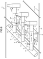
- FIG. 6 is a diagram illustrating a schematic configuration of a gas-insulated switchgear that is a target for locating a fault point by the fault-point-locating device according to the second embodiment of the present invention.
- the pressure sensors 15 are provided respectively on the busbar tank 11 and the connection tanks 13. That is, some of the tanks included in the gas-insulated switchgear 10, other than the breaker tank 12a, the breaker tank 12b, and the breaker tank 12c, are respectively provided with the pressure sensors 15.
- the pressure sensor 15 is not provided on any of the breaker tanks 12a, 12b, and 12c.
- the fault-point-locating device 1 has a configuration identical to that of the fault-point-locating device 1 illustrated in FIG. 1 .
- a pressure signal is input to the pressure-signal input unit 3 from the pressure sensors 15 provided respectively on the busbar tank 11 and the connection tanks 13.
- the determination unit 6 monitors whether a pressure increase has occurred in the busbar tank 11 and the connection tanks 13 on the basis of pressure signals from the pressure sensors 15 provided on the busbar tank 11 and the connection tanks 13. When the determination unit 6 determines that a pressure increase has occurred in any one of the busbar tank 11 and the connection tanks 13, the location processing unit 8 locates the tank in which a pressure increase is determined to have occurred as a fault point.
- the measurement unit 7 monitors whether the CTs 16a, 16b, and 16c have detected a current.
- a pressure increase is determined not to have occurred in any of the tanks other than the breaker tanks 12a, 12b, and 12c, that is, in any of the busbar tank 11 and the connection tanks 13, and when a current flowing between one of the breaker tanks 12a, 12b, and 12c and the grounding electrode 18 is out of phase with a current flowing between either of the other two breaker tanks and the grounding electrode 18, and a current flowing between the other of the other two breaker tanks and the grounding electrode 18, then the location processing unit 8 locates the one breaker tank as a fault point.
- the location processing unit 8 locates the fault point in the breaker tank 12a, the breaker tank 12b, and the breaker tank 12c on the basis of a measurement result of the waveform of the currents in the same manner as in the first embodiment. Also in the second embodiment, the function of the computation unit 2 included in the fault-point-locating device 1 is implemented by using a processing circuitry similarly to the first embodiment.
- the fault-point-locating device 1 can also reduce the number of CTs to be installed for measurement of a current waveform to the CTs 16a, 16b, and 16c.
- the breaker tanks 12a, 12b, and 12c do not need to be provided with the pressure sensors 15, so that the fault-point-locating device 1 can reduce the number of the pressure sensors 15 to be installed for locating a fault point.
- the fault-point-locating device 1 achieves an effect of reducing the number of constituent elements to be provided in the gas-insulated switchgear 10 to locate a fault point in a tank in which a breaker is accommodated.
- 1 fault-point-locating device 1 computation unit; 3 pressure-signal input unit; 4 current-signal input unit; 5 display unit; 6 determination unit; 7 measurement unit; 8 location processing unit; 10 gas-insulated switchgear; 11 busbar tank; 12a, 12b, 12c breaker tank; 13 connection tank; 14a, 14b, 14c stand; 15, 15a, 15b, 15c pressure sensor; 16a, 16b, 16c CT; 17 metal base; 18 grounding electrode; 19 grounding mesh; 21, 22, 23, 24, 25, 26, 27 ground-fault current; 28 position; 31 processing circuitry; 32 interface; 33 external storage device; 34 display device; 35 processor; 36 memory.
Landscapes
- Engineering & Computer Science (AREA)
- Physics & Mathematics (AREA)
- General Physics & Mathematics (AREA)
- Power Engineering (AREA)
- Manufacturing & Machinery (AREA)
- Locating Faults (AREA)
- Gas-Insulated Switchgears (AREA)
Abstract
Description
- The present invention relates to a fault-point-locating device that locates a fault point in a three-phase separating gas-insulated switchgear.
- A conventional fault-point-locating device monitors the pressure in each tank equivalent to a gas section, and detects an increase in the pressure caused by a ground fault or a short circuit, so as to locate a fault point where the ground fault or the short circuit has occurred. In a breaker tank in which a breaker is accommodated, the pressure in the tank can also be increased due to an arc generated during current interruption other than the ground fault or the short circuit. The fault-point-locating device is thus required to be capable of distinguishing a short circuit in the breaker tank from current interruption by a breaker.
- Patent Literature 1 discloses a fault-point-locating device provided with current transformers between a breaker tank and each of the tanks adjacent to the breaker tank, so as to monitor a ground fault in the breaker tank on the basis of the polarity of a current flowing through each of the current transformers. According to Patent Literature 1, in order to monitor a ground fault in the breaker tank forming a three-phase simultaneous gas-insulated switchgear, the current transformers are provided respectively between the breaker tank and a busbar tank, between the breaker tank and a cable head tank, and between the breaker tank and an earth.
-
Japanese Patent Application Laid-open No. H8-79923 - In a case where a three-phase separating gas-insulated switchgear monitors a ground fault in a breaker tank for each phase, when the technique disclosed in Patent Literature 1 described above is applied to the three-phase separating gas-insulated switchgear, the number of current transformers required for this gas-insulated switchgear is three times larger than that required for a three-phase simultaneous gas-insulated switchgear. Thus, many current transformers are needed for locating a fault point in the breaker tanks. According to the technique disclosed in Patent Literature 1 described above, there is a problem that the gas-insulated switchgear needs to be provided with many constituent elements to locate a fault point.
- The present invention has been achieved to solve the above problems, and an object of the present invention is to provide a fault-point-locating device that makes it possible to reduce the number of constituent elements to be provided in a gas-insulated switchgear to locate a fault point in a tank in which a breaker is accommodated.
- In order to solve the above problems and achieve the object, a fault-point-locating device according to the present invention locates a fault point in a gas-insulated switchgear including a first tank having a breaker for a first phase accommodated therein, a second tank having a breaker for a second phase accommodated therein, and a third tank having a breaker for a third phase accommodated therein. The fault-point-locating device according to the present invention comprises a measurement unit to measure a waveform of a current flowing between the first tank and a grounding electrode, a waveform of a current flowing between the second tank and the grounding electrode, and a waveform of a current flowing between the third tank and the grounding electrode, the first tank, the second tank, and the third tank being connected to the grounding electrode, and a location processing unit to perform a process of locating the fault point in the first tank, the second tank, and the third tank on the basis of a measurement result of a waveform of each of the currents.
- The fault-point-locating device according to the present invention has an effect where it is possible to reduce the number of constituent elements to be provided in a gas-insulated switchgear to locate a fault point in a tank in which a breaker is accommodated.
-
-
FIG. 1 is a block diagram illustrating a configuration of a fault-point-locating device according to a first embodiment of the present invention. -
FIG. 2 is a diagram illustrating a schematic configuration of a gas-insulated switchgear that is a target for locating a fault point by the fault-point-locating device illustrated inFIG. 1 . -
FIG. 3 is a diagram for explaining a process to be performed by a location processing unit included in the fault-point-locating device illustrated inFIG. 1 . -
FIG. 4 is a first diagram illustrating an example of a hardware configuration of the fault-point-locating device according to the first embodiment. -
FIG. 5 is a second diagram illustrating an example of the hardware configuration of the fault-point-locating device according to the first embodiment. -
FIG. 6 is a diagram illustrating a schematic configuration of a gas-insulated switchgear that is a target for locating a fault point by a fault-point-locating device according to a second embodiment of the present invention. - A fault-point-locating device according to embodiments of the present invention will be described in detail below with reference to the drawings. The present invention is not limited to the embodiments.
- First embodiment.
-
FIG. 1 is a block diagram illustrating a configuration of a fault-point-locating device according to a first embodiment of the present invention.FIG. 2 is a diagram illustrating a schematic configuration of a gas-insulated switchgear that is a target for locating a fault point by the fault-point-locating device illustrated inFIG. 1 . A gas-insulatedswitchgear 10 illustrated inFIG. 2 is installed in power facilities such as a power plant or a substation. - In the gas-insulated
switchgear 10, a voltage is applied to a busbar for three phases including a U-phase, a V-phase, and a W-phase. Wires for the three phases branch off from the busbar toward a target to/from which power is transmitted/received. Breakers are connected to branch wires that are the wires that branch off from the busbar. The busbar, the branch wires, and the breakers are accommodated respectively in tanks filled with insulating gas. The gas-insulatedswitchgear 10 is a so-called "three-phase separating gas-insulated switchgear" in which the branch wires for three phases are individually accommodated in separate tanks. In the three-phase separating gas-insulated switchgear, a ground fault may occur, while a phase-to-phase short circuit does not occur. - The gas-insulated
switchgear 10 includes abreaker tank 12a that is a first tank, abreaker tank 12b that is a second tank, and abreaker tank 12c that is a third tank. A breaker for a U-phase that is a first phase is accommodated in thebreaker tank 12a. A breaker for a V-phase that is a second phase is accommodated in thebreaker tank 12b. A breaker for a W-phase that is a third phase is accommodated in thebreaker tank 12c. The busbar is accommodated in abusbar tank 11. Tanks other than thebusbar tank 11 and thebreaker tanks connection tanks 13. A branch wire or a device connected to the branch wire is accommodated in each of theconnection tanks 13. - The
busbar tank 11, thebreaker tanks connection tanks 13 illustrated inFIG. 1 form a single unit. A plurality of units are provided in the gas-insulatedswitchgear 10. - The
breaker tank 12a is installed on astand 14a. Thebreaker tank 12b is installed on astand 14b. Thebreaker tank 12c is installed on astand 14c. Thebusbar tank 11 and theconnection tanks 13 are installed on their respective stands similarly to thebreaker tanks FIG. 2 omits illustrations of the stand on which thebusbar tank 11 is installed, and the stands on which theconnection tanks 13 are installed. - The
stands metal base 17. Thestand 14a supports thebreaker tank 12a on themetal base 17. Thestand 14b supports thebreaker tank 12b on themetal base 17. Thestand 14c supports thebreaker tank 12c on themetal base 17. Themetal base 17 is provided in each unit. - A
grounding electrode 18 is connected to themetal base 17. Thebreaker tanks grounding electrode 18 through thestands metal base 17. Thegrounding electrode 18 connects themetal base 17 to agrounding mesh 19. Thegrounding mesh 19 is provided underground in the power facilities. Thegrounding mesh 19 is made of copper wires laid into a net. The spacing between the copper wires is approximately 1 meter to 10 meters. Each of the copper wires has a cross-sectional area of approximately 100 mm2. - The
busbar tank 11, thebreaker tanks connection tanks 13 are provided respectively withpressure sensors 15. Each of thepressure sensors 15 detects the pressure in the tank. Thepressure sensor 15 provided on thebreaker tank 12a is referred to as "pressure sensor 15a". Thepressure sensor 15 provided on thebreaker tank 12b is referred to as "pressure sensor 15b". Thepressure sensor 15 provided on thebreaker tank 12c is referred to as "pressure sensor 15c" . - Current transformers (CTs) 16a, 16b, and 16c detect a current. The
CT 16a is attached to one of the columns that form thestand 14a. TheCT 16b is attached to one of the columns that form thestand 14b. TheCT 16c is attached to one of the columns that form thestand 14c. TheCT - A fault-point-locating device 1 illustrated in
FIG. 1 locates a fault point in the gas-insulatedswitchgear 10. The fault-point-locating device 1 is installed along with the gas-insulatedswitchgear 10 in the power facilities. Each of thepressure sensors 15 provided in the gas-insulatedswitchgear 10 is connected to the fault-point-locating device 1 through a signal line. Each of thepressure sensors 15 outputs a pressure signal indicating the result of pressure detection to the fault-point-locating device 1. Each of theCTs switchgear 10 is connected to the fault-point-locating device 1 through a signal line. Each of theCTs - The fault-point-locating device 1 includes a computation unit 2 to perform various types of computational processing, a pressure-signal input unit 3 to which a pressure signal is input from each of the
pressure sensors 15, a current-signal input unit 4 to which a current signal is input from each of theCTs display unit 5 to display information. The computation unit 2 includes a determination unit 6 to determine whether a pressure increase has occurred in each of the tanks, a measurement unit 7 to measure a current waveform, and alocation processing unit 8 to perform a process of locating a fault point. The determination unit 6 processes a pressure signal to determine whether a pressure increase has occurred. The measurement unit 7 processes a current signal to measure a current waveform. Thedisplay unit 5 displays the result of location of the fault point by thelocation processing unit 8. - Location of a fault point by the fault-point-locating device 1 is described here. The determination unit 6 monitors whether a pressure increase has occurred in the
busbar tank 11 and theconnection tanks 13 on the basis of pressure signals from thepressure sensors 15 provided on thebusbar tank 11 and theconnection tanks 13. When the determination unit 6 determines that a pressure increase has occurred in any one of thebusbar tank 11 and theconnection tanks 13, thelocation processing unit 8 locates the tank in which a pressure increase is determined to have occurred as a fault point. As described above, when a ground fault has occurred in any of thebusbar tank 11 and theconnection tanks 13, thelocation processing unit 8 determines a fault point in thebusbar tank 11 and theconnection tanks 13 on the basis of the result of determination performed by the determination unit 6 regarding whether a pressure increase has occurred. - On the basis of pressure signals from the
pressure sensors breaker tanks CTs CTs breaker tank 12a via thestand 14a to thegrounding electrode 18, monitors whether a current flows from thebreaker tank 12b via thestand 14b to thegrounding electrode 18, and monitors whether a current flows from thebreaker tank 12c via thestand 14c to thegrounding electrode 18. When theCTs - When a pressure increase is determined to have occurred in one of the
breaker tanks electrode 18 is out of phase with a current flowing between either of the other two breaker tanks and the groundingelectrode 18, and a current flowing between the other of the other two breaker tanks and the groundingelectrode 18, then thelocation processing unit 8 locates the one breaker tank as a fault point. In the manner as described above, on the basis of the determination result of whether a pressure increase has occurred, and the measurement result of the waveform of the currents, thelocation processing unit 8 performs a process of locating a fault point in thebreaker tank 12a, thebreaker tank 12b, and thebreaker tank 12c. - As illustrated in
FIG. 2 , it is assumed that a ground fault has occurred at aposition 28 in thebreaker tank 12a. Due to the occurrence of a ground fault in thebreaker tank 12a, the pressure in thebreaker tank 12a increases. - Due to the ground fault, a ground-fault current 25, that is a portion of the current having flowed between the branch wire and the
breaker tank 12a, flows from thebreaker tank 12a through theconnection tank 13 and thebusbar tank 11 to a transformer that is a power supply in the power facilities. In addition, a ground-fault current 21, that is a portion of the current having flowed between the branch wire and thebreaker tank 12a, flows through thestand 14a to themetal base 17. TheCT 16a detects the ground-fault current 21. A ground-fault current 24, that is a portion of the ground-fault current 21 having flowed to themetal base 17, flows from themetal base 17 through the groundingelectrode 18 and thegrounding mesh 19 to the transformer. - A ground-fault current 22, that is a portion of the ground-fault current 21 having flowed to the
metal base 17, flows from themetal base 17 through thestand 14b to thebreaker tank 12b. TheCT 16b detects the ground-fault current 22. A ground-fault current 26, that is a portion of the ground-fault current 22 having flowed to thebreaker tank 12b, flows from thebreaker tank 12b through theconnection tank 13 and thebusbar tank 11 to the transformer. - A ground-fault current 23, that is a portion of the ground-fault current 21 having flowed to the
metal base 17, flows from themetal base 17 through thestand 14c to thebreaker tank 12c. TheCT 16c detects the ground-fault current 23. A ground-fault current 27, that is a portion of the ground-fault current 22 having flowed to thebreaker tank 12c, flows from thebreaker tank 12c through theconnection tank 13 and thebusbar tank 11 to the transformer. -
FIG. 3 is a diagram for explaining a process to be performed by the location processing unit included in the fault-point-locating device illustrated inFIG. 1 . A graph illustrated on the upper side ofFIG. 3 shows a relation between time and a pressure detected by thepressure sensor 15a. A graph illustrated on the lower side ofFIG. 3 shows a relation between time and a current detected by theCTs - A time T1 represents the time at which a ground fault has occurred at the
position 28. When a ground fault has occurred at theposition 28, the gas-insulatedswitchgear 10 causes respective breakers in thebreaker tanks - Since a ground fault has occurred at the
position 28, the pressure detected by thepressure sensor 15a increases during the period from the time T1 to the time T2. At or after the time T2, the pressure gradually decreases due to heat dissipation from thebreaker tank 12a. When the pressure detected by thepressure sensor 15a starts increasing, and then the amount of pressure increase becomes greater than a threshold ΔP set in advance, then the determination unit 6 determines that a pressure increase has occurred. The threshold ΔP is set for each individual tank on the basis of the result of calculation of a minimum pressure increase at the occurrence of a ground fault. It is allowable that the threshold ΔP is set to a different value for each individual tank, or is set to a common value among all the tanks provided in the gas-insulatedswitchgear 10. - As a ground fault has occurred at the
position 28, the ground-fault currents CT 16a detects the ground-fault current 21, the measurement unit 7 measures the current waveform of the ground-fault current 21 on the basis of a current signal from theCT 16a. When theCT 16b detects the ground-fault current 22, the measurement unit 7 measures the current waveform of the ground-fault current 22 on the basis of a current signal from theCT 16b. When theCT 16c detects the ground-fault current 23, the measurement unit 7 measures the current waveform of the ground-fault current 23 on the basis of a current signal from theCT 16c. The graph on the lower side ofFIG. 3 illustrates a current waveform I1 of the ground-fault current 21 and a current waveform I2 of the ground-fault current 22. - Since the ground-fault current 21 and the ground-fault current 22 flow in directions opposite to each other, the current waveform I1 and the current waveform I2 have opposite phases to each other. That is, the ground-fault current 21 is 180 degrees out of phase with the ground-
fault current 22. Since the ground-fault current 23 and the ground-fault current 22 flow in the same direction, the current waveform of the ground-fault current 23 is in phase with thecurrent waveform 12. That is, there is not phase shifting between the ground-fault current 23 and the ground-fault current 22. Therefore, only the current waveform I1, that is one of the three current waveforms obtained by measurement by the measurement unit 7, is out of phase with the other two current waveforms. Illustrations of the current waveform of the ground-fault current 23 are omitted since the current waveform of the ground-fault current 23 is identical to the current waveform I2 except that the current waveform of the ground-fault current 23 has an amplitude different from that of thecurrent waveform 12. - The
location processing unit 8 locates thebreaker tank 12a as a fault point on the basis of the determination in the determination unit 6 that a pressure increase has occurred in thebreaker tank 12a, and on the basis of the fact that only the current waveform I1 of the current waveforms measured by the measurement unit 7 is out of phase with the other current waveforms. When a ground fault has occurred in thebreaker tank 12b or thebreaker tank 12c, thelocation processing unit 8 also locates the fault point in the same manner as performed on thebreaker tank 12a. - In the
breaker tanks fault currents fault currents location processing unit 8 can distinguish a short circuit having occurred in thebreaker tanks - The path through which the ground-
fault currents breaker tanks connection tanks 13 and thebusbar tank 11 to the power supply has an impedance lower than the impedance on the path through which the ground-fault current 24 flows through the groundingelectrode 18 and thegrounding mesh 19 to the power supply. A specific example is given in which thegrounding mesh 19 has an impedance per unit distance, where the value of impedance is of the order of magnitude of 1 ohm, and in contrast to that, the surface of the tank has an impedance per unit distance, where the value of impedance is of the order of magnitude of 10 milliohms. The value of impedance on the path passing through the surface of the tank is smaller by an order of magnitude than the value of impedance on the path passing through thegrounding mesh 19. Accordingly, the paths of the ground-fault currents fault current 24. - When the ground-fault current 21 flows to the
metal base 17, then due to the difference between the impedance values as described above, the ground-fault current 24 flows to thegrounding electrode 18, and additionally the ground-fault currents 22 and 23 flow through thestands breaker tanks fault currents breaker tanks busbar tank 11. In this manner, the ground-fault current 22 flowing through thestand 14b to thebreaker tank 12b is generated, and the ground-fault current 23 flowing through thestand 14c to thebreaker tank 12c is generated, making it possible for theCTs fault currents 22 and 23 whose current amount is sufficient for the measurement unit 7 to measure a current waveform. - In the fault-point-locating device 1, three
CTs breaker tanks CTs breaker tank 12a and each of its adjacent tanks, between thebreaker tank 12b and each of its adjacent tanks, and between thebreaker tank 12c and each of its adjacent tanks. - The
breaker tanks grounding electrode 18 through themetal base 17. Thestands metal base 17. Thebreaker tanks breaker tanks grounding mesh 19. In this case, the ground-fault current 21 having flowed from thestand 14a to thegrounding mesh 19 partially flows through thegrounding mesh 19 to thestand 14b and to thestand 14c. This can result in generating the ground-fault currents 22 and 23 similarly to the case when themetal base 17 is used. - Next, a hardware configuration of the fault-point-locating device 1 is described. The function of the computation unit 2 included in the fault-point-locating device 1 is implemented by using a processing circuitry. The processing circuitry is dedicated hardware installed in the fault-point-locating device 1. The processing circuitry may be a processor that executes programs stored in a memory.
-
FIG. 4 is a first diagram illustrating an example of the hardware configuration of the fault-point-locating device according to the first embodiment.FIG. 4 illustrates the hardware configuration of the fault-point-locating device 1 when the functions of the fault-point-locating device 1 are implemented by using the dedicated hardware. The fault-point-locating device 1 includes a processing circuitry 31 to perform various types of processing, an interface 32 through which the fault-point-locating device 1 is connected to external devices, an external storage device 33 to store therein various types of information, and adisplay device 34 that is an output device. The processing circuitry 31, the interface 32, the external storage device 33, and thedisplay device 34 are connected to be capable of communicating with each other. - The processing circuitry 31 as dedicated hardware is a single circuit, a combined circuit, a programmed processor, a parallel-programmed processor, an ASIC (Application Specific Integrated Circuit), an FPGA (Field-Programmable Gate Array), or a combination thereof. The functions of the determination unit 6, measurement unit 7, and the
location processing unit 8 are implemented by using the processing circuitry 31. - The functions of the pressure-signal input unit 3 and the current-signal input unit 4 are implemented by using the interface 32. The external storage device 33 stores therein the result of location by the
location processing unit 8 and the threshold ΔP to be used for determination by the determination unit 6. Thedisplay device 34 displays the result of location and other information on a screen. The function of thedisplay unit 5 is implemented by using thedisplay device 34. It is allowable that the fault-point-locating device 1 includes an input device through which the threshold ΔP and other information is input. -
FIG. 5 is a second diagram illustrating an example of the hardware configuration of the fault-point-locating device according to the first embodiment.FIG. 5 illustrates the hardware configuration of the fault-point-locating device when the function of the computation unit 2 is implemented by using hardware that executes the programs. The fault-point-locating device 1 includes aprocessor 35, a memory 36, the interface 32, the external storage device 33, and thedisplay device 34. Theprocessor 35, the memory 36, the interface 32, the external storage device 33, and thedisplay device 34 are connected to be capable of communicating with each other. - The
processor 35 is a CPU (Central Processing Unit), a processing device, a computation device, a microprocessor, a microcomputer, or a DSP (Digital Signal Processor). Each of the functions of the determination unit 6, the measurement unit 7, and thelocation processing unit 8 is implemented by theprocessor 35, software, firmware, or a combination of software and firmware. The software or firmware is described as a program to be stored in the memory 36 that is a built-in memory. The memory 36 is a nonvolatile or volatile semiconductor memory, and is a RAM (Random Access Memory), a ROM (Read Only Memory), a flash memory, an EPROM (Erasable Programmable Read Only Memory), or an EEPROM (registered trademark) (Electrically Erasable Programmable Read Only Memory). - According to the first embodiment, the fault-point-locating device 1 measures a waveform of a current flowing between the
breaker tank 12a and the groundingelectrode 18, a current flowing between thebreaker tank 12b and the groundingelectrode 18, and a current flowing between thebreaker tank 12c and the groundingelectrode 18. On the basis of a determination result of whether a pressure increase has occurred in thebreaker tanks breaker tanks CTs switchgear 10 to locate a fault point in a tank in which a breaker is accommodated. - Second embodiment.
- In the fault-point-locating device 1 according to a second embodiment, when it is determined that a pressure increase has not occurred in any of the tanks included in the fault-point-locating device 1, that are other than the
breaker tanks breaker tanks breaker tank 12a and the groundingelectrode 18, a current flowing between thebreaker tank 12b and the groundingelectrode 18, and a current flowing between thebreaker tank 12c and the groundingelectrode 18. In the second embodiment, constituent elements identical to those of the first embodiment are denoted by like reference signs, and configurations different from those of the first embodiment are mainly described. -
FIG. 6 is a diagram illustrating a schematic configuration of a gas-insulated switchgear that is a target for locating a fault point by the fault-point-locating device according to the second embodiment of the present invention. In the gas-insulatedswitchgear 10 illustrated inFIG. 6 , thepressure sensors 15 are provided respectively on thebusbar tank 11 and theconnection tanks 13. That is, some of the tanks included in the gas-insulatedswitchgear 10, other than thebreaker tank 12a, thebreaker tank 12b, and thebreaker tank 12c, are respectively provided with thepressure sensors 15. In the second embodiment, thepressure sensor 15 is not provided on any of thebreaker tanks - The fault-point-locating device 1 according to the second embodiment has a configuration identical to that of the fault-point-locating device 1 illustrated in
FIG. 1 . In the second embodiment, a pressure signal is input to the pressure-signal input unit 3 from thepressure sensors 15 provided respectively on thebusbar tank 11 and theconnection tanks 13. The determination unit 6 monitors whether a pressure increase has occurred in thebusbar tank 11 and theconnection tanks 13 on the basis of pressure signals from thepressure sensors 15 provided on thebusbar tank 11 and theconnection tanks 13. When the determination unit 6 determines that a pressure increase has occurred in any one of thebusbar tank 11 and theconnection tanks 13, thelocation processing unit 8 locates the tank in which a pressure increase is determined to have occurred as a fault point. - On the basis of current signals from the
CTs CTs breaker tanks busbar tank 11 and theconnection tanks 13, and when a current flowing between one of thebreaker tanks electrode 18 is out of phase with a current flowing between either of the other two breaker tanks and the groundingelectrode 18, and a current flowing between the other of the other two breaker tanks and the groundingelectrode 18, then thelocation processing unit 8 locates the one breaker tank as a fault point. When a pressure increase is determined not to have occurred in any of thebusbar tank 11 and theconnection tanks 13, thelocation processing unit 8 locates the fault point in thebreaker tank 12a, thebreaker tank 12b, and thebreaker tank 12c on the basis of a measurement result of the waveform of the currents in the same manner as in the first embodiment. Also in the second embodiment, the function of the computation unit 2 included in the fault-point-locating device 1 is implemented by using a processing circuitry similarly to the first embodiment. - In the same manner as in the first embodiment, the fault-point-locating device 1 according to the second embodiment can also reduce the number of CTs to be installed for measurement of a current waveform to the
CTs breaker tanks pressure sensors 15, so that the fault-point-locating device 1 can reduce the number of thepressure sensors 15 to be installed for locating a fault point. With this configuration, the fault-point-locating device 1 achieves an effect of reducing the number of constituent elements to be provided in the gas-insulatedswitchgear 10 to locate a fault point in a tank in which a breaker is accommodated. - The configurations described in the above embodiments are only examples of the content of the present invention. The configurations can be combined with other well-known techniques, and part of each of the configurations can be omitted or modified without departing from the scope of the present invention.
- 1 fault-point-locating device; 2 computation unit; 3 pressure-signal input unit; 4 current-signal input unit; 5 display unit; 6 determination unit; 7 measurement unit; 8 location processing unit; 10 gas-insulated switchgear; 11 busbar tank; 12a, 12b, 12c breaker tank; 13 connection tank; 14a, 14b, 14c stand; 15, 15a, 15b, 15c pressure sensor; 16a, 16b, 16c CT; 17 metal base; 18 grounding electrode; 19 grounding mesh; 21, 22, 23, 24, 25, 26, 27 ground-fault current; 28 position; 31 processing circuitry; 32 interface; 33 external storage device; 34 display device; 35 processor; 36 memory.
Claims (5)
- A fault-point-locating device that locates a fault point in a gas-insulated switchgear including a first tank having a breaker for a first phase accommodated therein, a second tank having a breaker for a second phase accommodated therein, and a third tank having a breaker for a third phase accommodated therein, the fault-point-locating device comprising:a measurement unit to measure a waveform of a current flowing between the first tank and a grounding electrode, a waveform of a current flowing between the second tank and the grounding electrode, and a waveform of a current flowing between the third tank and the grounding electrode, the first tank, the second tank, and the third tank being connected to the grounding electrode; anda location processing unit to perform a process of locating the fault point in the first tank, the second tank, and the third tank on a basis of a measurement result of a waveform of each of the currents.
- The fault-point-locating device according to claim 1, comprising a determination unit to determine whether a pressure increase has occurred in each of the first tank, the second tank, and the third tank, wherein
the location processing unit performs the process of locating the fault point on a basis of a determination result of whether the pressure increase has occurred, and a measurement result of a waveform of each of the currents. - The fault-point-locating device according to claim 2, wherein when the pressure increase is determined to have occurred in one of the first tank, the second tank, and the third tank, and when a current flowing between the one tank and the grounding electrode is out of phase with a current flowing between either of the other two tanks and the grounding electrode, and a current flowing between the other of the other two tanks and the grounding electrode, then the location processing unit locates the one tank as the fault point.
- The fault-point-locating device according to claim 1, comprising a determination unit to determine whether a pressure increase has occurred in each of tanks that are included in the gas-insulated switchgear, and that are other than the first tank, the second tank, and the third tank, wherein
when the pressure increase is determined not to have occurred in any of tanks other than the first tank, the second tank, and the third tank, and when a current flowing between one of the first tank, the second tank, and the third tank, and the grounding electrode is out of phase with a current flowing between either of the other two tanks and the grounding electrode, and a current flowing between the other of the other two tanks and the grounding electrode, then the location processing unit locates the one tank as the fault point. - The fault-point-locating device according to claim 1, wherein the measurement unit measures a waveform of a current detected by a current transformer attached to a stand supporting the first tank, a waveform of a current detected by a current transformer attached to a stand supporting the second tank, and a waveform of a current detected by a current transformer attached to a stand supporting the third tank.
Applications Claiming Priority (1)
| Application Number | Priority Date | Filing Date | Title |
|---|---|---|---|
| PCT/JP2019/017021 WO2020217275A1 (en) | 2019-04-22 | 2019-04-22 | Fault-point-locating device |
Publications (3)
| Publication Number | Publication Date |
|---|---|
| EP3961832A1 true EP3961832A1 (en) | 2022-03-02 |
| EP3961832A4 EP3961832A4 (en) | 2022-05-04 |
| EP3961832B1 EP3961832B1 (en) | 2024-12-11 |
Family
ID=69320987
Family Applications (1)
| Application Number | Title | Priority Date | Filing Date |
|---|---|---|---|
| EP19926470.6A Active EP3961832B1 (en) | 2019-04-22 | 2019-04-22 | Fault-point-locating device |
Country Status (3)
| Country | Link |
|---|---|
| EP (1) | EP3961832B1 (en) |
| JP (1) | JP6641541B1 (en) |
| WO (1) | WO2020217275A1 (en) |
Family Cites Families (10)
| Publication number | Priority date | Publication date | Assignee | Title |
|---|---|---|---|---|
| JPS57125189A (en) * | 1981-01-28 | 1982-08-04 | Tokyo Shibaura Electric Co | Device for orientating trouble point |
| JP2619038B2 (en) * | 1989-01-10 | 1997-06-11 | 株式会社日立製作所 | Substation protection systems and circuit breakers |
| JPH02275372A (en) * | 1989-04-15 | 1990-11-09 | Kandenko Co Ltd | Ground fault current sensor and ground fault location method |
| JPH06313776A (en) * | 1993-04-30 | 1994-11-08 | Meidensha Corp | Detector of ground fault current of grounding line |
| JPH07245832A (en) * | 1994-03-07 | 1995-09-19 | Takaoka Electric Mfg Co Ltd | Gas insulated switchgear |
| JPH0823628A (en) * | 1994-07-06 | 1996-01-23 | Nissin Electric Co Ltd | Method and device for locating accident point of gas insulated switchgear |
| JPH0879923A (en) * | 1994-08-31 | 1996-03-22 | Nissin Electric Co Ltd | Ground fault locator |
| JP3684291B2 (en) * | 1997-07-11 | 2005-08-17 | 三菱電機株式会社 | Power system total abnormality judgment device and protection device |
| JP4268314B2 (en) * | 2000-04-27 | 2009-05-27 | パナソニック電工電路株式会社 | Cable failure display device |
| JP4377542B2 (en) * | 2000-10-20 | 2009-12-02 | 株式会社東芝 | Internal partial discharge monitoring device for high voltage equipment |
-
2019
- 2019-04-22 EP EP19926470.6A patent/EP3961832B1/en active Active
- 2019-04-22 JP JP2019548091A patent/JP6641541B1/en active Active
- 2019-04-22 WO PCT/JP2019/017021 patent/WO2020217275A1/en not_active Ceased
Also Published As
| Publication number | Publication date |
|---|---|
| EP3961832B1 (en) | 2024-12-11 |
| EP3961832A4 (en) | 2022-05-04 |
| JPWO2020217275A1 (en) | 2021-05-06 |
| JP6641541B1 (en) | 2020-02-05 |
| WO2020217275A1 (en) | 2020-10-29 |
Similar Documents
| Publication | Publication Date | Title |
|---|---|---|
| EP2676346B1 (en) | Method and arrangement for detecting an internal failure in h-bridge connected capacitor bank | |
| KR102050255B1 (en) | Method and test device for testing wiring of transducers | |
| CN106918778B (en) | Method for loose joint detection in medium voltage switchgear and medium voltage switchgear | |
| KR101748554B1 (en) | Leakage current calculation device and leakage current calculation method | |
| ES2914042T3 (en) | Method and apparatus for commissioning branch circuit voltage sensors and branch circuit current sensors for branch circuit monitoring systems | |
| US10191102B2 (en) | Automatic current transformer polarity correction | |
| EP3304099B1 (en) | Method and apparatus to commission voltage sensors and branch circuit current sensors for branch circuit monitoring systems | |
| CN103852691A (en) | Directional detection of a fault in a network of a grounding system with compensated or insulated neutral point | |
| KR101916362B1 (en) | Intelligent power facility failure prediction system and method using three-phase leakage current measurement method by insulation deterioration | |
| KR101986221B1 (en) | 3-phase 4-wire electrical installation hot-line insulation resistance measurement method and device | |
| KR101041398B1 (en) | Switchgear current monitoring device | |
| WO2020026163A2 (en) | A method and a device for supervision of a voltage transformer | |
| EP3961832A1 (en) | Fault-point-locating device | |
| US8022709B2 (en) | Method and apparatus for determining circular characteristic | |
| JP2017194465A (en) | Monitoring device | |
| JP4121979B2 (en) | Non-grounded circuit insulation monitoring method and apparatus | |
| JP5679480B2 (en) | Indirect AC megger measuring instrument and insulation resistance measuring method | |
| KR101986518B1 (en) | Terminal Board for Measurement Continuity Electric Resistanc of Structure | |
| JP5241434B2 (en) | Cable section accident detection device | |
| RU2788519C1 (en) | Method for disconnecting a damaged connection with a single-phase earth fault in networks with an isolated neutral | |
| CN100533903C (en) | Insulation diagnostic device | |
| JP2010048577A (en) | System discrimination device | |
| KR20190127401A (en) | Gas insulated switchgear | |
| JPH0650330B2 (en) | Deterioration diagnosis method for zinc oxide type arrester | |
| ES2588260A1 (en) | Procedure and device for the determination of the condition of the neutral driver in an electrical installation (Machine-translation by Google Translate, not legally binding) |
Legal Events
| Date | Code | Title | Description |
|---|---|---|---|
| STAA | Information on the status of an ep patent application or granted ep patent |
Free format text: STATUS: THE INTERNATIONAL PUBLICATION HAS BEEN MADE |
|
| PUAI | Public reference made under article 153(3) epc to a published international application that has entered the european phase |
Free format text: ORIGINAL CODE: 0009012 |
|
| STAA | Information on the status of an ep patent application or granted ep patent |
Free format text: STATUS: REQUEST FOR EXAMINATION WAS MADE |
|
| 17P | Request for examination filed |
Effective date: 20210914 |
|
| AK | Designated contracting states |
Kind code of ref document: A1 Designated state(s): AL AT BE BG CH CY CZ DE DK EE ES FI FR GB GR HR HU IE IS IT LI LT LU LV MC MK MT NL NO PL PT RO RS SE SI SK SM TR |
|
| A4 | Supplementary search report drawn up and despatched |
Effective date: 20220404 |
|
| RIC1 | Information provided on ipc code assigned before grant |
Ipc: G01R 31/14 20060101ALI20220329BHEP Ipc: G01R 31/12 20200101ALI20220329BHEP Ipc: G01R 31/327 20060101ALI20220329BHEP Ipc: H02B 13/075 20060101ALI20220329BHEP Ipc: H02B 13/035 20060101ALI20220329BHEP Ipc: H02B 3/00 20060101ALI20220329BHEP Ipc: H02B 13/065 20060101AFI20220329BHEP |
|
| DAV | Request for validation of the european patent (deleted) | ||
| DAX | Request for extension of the european patent (deleted) | ||
| GRAP | Despatch of communication of intention to grant a patent |
Free format text: ORIGINAL CODE: EPIDOSNIGR1 |
|
| STAA | Information on the status of an ep patent application or granted ep patent |
Free format text: STATUS: GRANT OF PATENT IS INTENDED |
|
| INTG | Intention to grant announced |
Effective date: 20240719 |
|
| GRAS | Grant fee paid |
Free format text: ORIGINAL CODE: EPIDOSNIGR3 |
|
| GRAA | (expected) grant |
Free format text: ORIGINAL CODE: 0009210 |
|
| STAA | Information on the status of an ep patent application or granted ep patent |
Free format text: STATUS: THE PATENT HAS BEEN GRANTED |
|
| AK | Designated contracting states |
Kind code of ref document: B1 Designated state(s): AL AT BE BG CH CY CZ DE DK EE ES FI FR GB GR HR HU IE IS IT LI LT LU LV MC MK MT NL NO PL PT RO RS SE SI SK SM TR |
|
| REG | Reference to a national code |
Ref country code: GB Ref legal event code: FG4D |
|
| REG | Reference to a national code |
Ref country code: CH Ref legal event code: EP |
|
| REG | Reference to a national code |
Ref country code: IE Ref legal event code: FG4D |
|
| REG | Reference to a national code |
Ref country code: DE Ref legal event code: R096 Ref document number: 602019063519 Country of ref document: DE |
|
| REG | Reference to a national code |
Ref country code: LT Ref legal event code: MG9D |
|
| PG25 | Lapsed in a contracting state [announced via postgrant information from national office to epo] |
Ref country code: HR Free format text: LAPSE BECAUSE OF FAILURE TO SUBMIT A TRANSLATION OF THE DESCRIPTION OR TO PAY THE FEE WITHIN THE PRESCRIBED TIME-LIMIT Effective date: 20241211 |
|
| PG25 | Lapsed in a contracting state [announced via postgrant information from national office to epo] |
Ref country code: FI Free format text: LAPSE BECAUSE OF FAILURE TO SUBMIT A TRANSLATION OF THE DESCRIPTION OR TO PAY THE FEE WITHIN THE PRESCRIBED TIME-LIMIT Effective date: 20241211 |
|
| PG25 | Lapsed in a contracting state [announced via postgrant information from national office to epo] |
Ref country code: BG Free format text: LAPSE BECAUSE OF FAILURE TO SUBMIT A TRANSLATION OF THE DESCRIPTION OR TO PAY THE FEE WITHIN THE PRESCRIBED TIME-LIMIT Effective date: 20241211 |
|
| REG | Reference to a national code |
Ref country code: NL Ref legal event code: MP Effective date: 20241211 |
|
| PG25 | Lapsed in a contracting state [announced via postgrant information from national office to epo] |
Ref country code: ES Free format text: LAPSE BECAUSE OF FAILURE TO SUBMIT A TRANSLATION OF THE DESCRIPTION OR TO PAY THE FEE WITHIN THE PRESCRIBED TIME-LIMIT Effective date: 20241211 |
|
| PG25 | Lapsed in a contracting state [announced via postgrant information from national office to epo] |
Ref country code: NO Free format text: LAPSE BECAUSE OF FAILURE TO SUBMIT A TRANSLATION OF THE DESCRIPTION OR TO PAY THE FEE WITHIN THE PRESCRIBED TIME-LIMIT Effective date: 20250311 |
|
| PG25 | Lapsed in a contracting state [announced via postgrant information from national office to epo] |
Ref country code: LV Free format text: LAPSE BECAUSE OF FAILURE TO SUBMIT A TRANSLATION OF THE DESCRIPTION OR TO PAY THE FEE WITHIN THE PRESCRIBED TIME-LIMIT Effective date: 20241211 Ref country code: GR Free format text: LAPSE BECAUSE OF FAILURE TO SUBMIT A TRANSLATION OF THE DESCRIPTION OR TO PAY THE FEE WITHIN THE PRESCRIBED TIME-LIMIT Effective date: 20250312 |
|
| PG25 | Lapsed in a contracting state [announced via postgrant information from national office to epo] |
Ref country code: RS Free format text: LAPSE BECAUSE OF FAILURE TO SUBMIT A TRANSLATION OF THE DESCRIPTION OR TO PAY THE FEE WITHIN THE PRESCRIBED TIME-LIMIT Effective date: 20250311 |
|
| PG25 | Lapsed in a contracting state [announced via postgrant information from national office to epo] |
Ref country code: NL Free format text: LAPSE BECAUSE OF FAILURE TO SUBMIT A TRANSLATION OF THE DESCRIPTION OR TO PAY THE FEE WITHIN THE PRESCRIBED TIME-LIMIT Effective date: 20241211 |
|
| REG | Reference to a national code |
Ref country code: AT Ref legal event code: MK05 Ref document number: 1751137 Country of ref document: AT Kind code of ref document: T Effective date: 20241211 |
|
| PG25 | Lapsed in a contracting state [announced via postgrant information from national office to epo] |
Ref country code: SM Free format text: LAPSE BECAUSE OF FAILURE TO SUBMIT A TRANSLATION OF THE DESCRIPTION OR TO PAY THE FEE WITHIN THE PRESCRIBED TIME-LIMIT Effective date: 20241211 |
|
| PG25 | Lapsed in a contracting state [announced via postgrant information from national office to epo] |
Ref country code: PL Free format text: LAPSE BECAUSE OF FAILURE TO SUBMIT A TRANSLATION OF THE DESCRIPTION OR TO PAY THE FEE WITHIN THE PRESCRIBED TIME-LIMIT Effective date: 20241211 |
|
| PG25 | Lapsed in a contracting state [announced via postgrant information from national office to epo] |
Ref country code: IS Free format text: LAPSE BECAUSE OF FAILURE TO SUBMIT A TRANSLATION OF THE DESCRIPTION OR TO PAY THE FEE WITHIN THE PRESCRIBED TIME-LIMIT Effective date: 20250411 |
|
| PG25 | Lapsed in a contracting state [announced via postgrant information from national office to epo] |
Ref country code: PT Free format text: LAPSE BECAUSE OF FAILURE TO SUBMIT A TRANSLATION OF THE DESCRIPTION OR TO PAY THE FEE WITHIN THE PRESCRIBED TIME-LIMIT Effective date: 20250411 |
|
| PG25 | Lapsed in a contracting state [announced via postgrant information from national office to epo] |
Ref country code: EE Free format text: LAPSE BECAUSE OF FAILURE TO SUBMIT A TRANSLATION OF THE DESCRIPTION OR TO PAY THE FEE WITHIN THE PRESCRIBED TIME-LIMIT Effective date: 20241211 |
|
| PGFP | Annual fee paid to national office [announced via postgrant information from national office to epo] |
Ref country code: CH Payment date: 20250501 Year of fee payment: 7 |
|
| PG25 | Lapsed in a contracting state [announced via postgrant information from national office to epo] |
Ref country code: AT Free format text: LAPSE BECAUSE OF FAILURE TO SUBMIT A TRANSLATION OF THE DESCRIPTION OR TO PAY THE FEE WITHIN THE PRESCRIBED TIME-LIMIT Effective date: 20241211 Ref country code: RO Free format text: LAPSE BECAUSE OF FAILURE TO SUBMIT A TRANSLATION OF THE DESCRIPTION OR TO PAY THE FEE WITHIN THE PRESCRIBED TIME-LIMIT Effective date: 20241211 |
|
| PG25 | Lapsed in a contracting state [announced via postgrant information from national office to epo] |
Ref country code: SK Free format text: LAPSE BECAUSE OF FAILURE TO SUBMIT A TRANSLATION OF THE DESCRIPTION OR TO PAY THE FEE WITHIN THE PRESCRIBED TIME-LIMIT Effective date: 20241211 |
|
| PG25 | Lapsed in a contracting state [announced via postgrant information from national office to epo] |
Ref country code: CZ Free format text: LAPSE BECAUSE OF FAILURE TO SUBMIT A TRANSLATION OF THE DESCRIPTION OR TO PAY THE FEE WITHIN THE PRESCRIBED TIME-LIMIT Effective date: 20241211 |
|
| PG25 | Lapsed in a contracting state [announced via postgrant information from national office to epo] |
Ref country code: IT Free format text: LAPSE BECAUSE OF FAILURE TO SUBMIT A TRANSLATION OF THE DESCRIPTION OR TO PAY THE FEE WITHIN THE PRESCRIBED TIME-LIMIT Effective date: 20241211 |
|
| PG25 | Lapsed in a contracting state [announced via postgrant information from national office to epo] |
Ref country code: SE Free format text: LAPSE BECAUSE OF FAILURE TO SUBMIT A TRANSLATION OF THE DESCRIPTION OR TO PAY THE FEE WITHIN THE PRESCRIBED TIME-LIMIT Effective date: 20241211 |
|
| REG | Reference to a national code |
Ref country code: DE Ref legal event code: R097 Ref document number: 602019063519 Country of ref document: DE |
|
| P01 | Opt-out of the competence of the unified patent court (upc) registered |
Free format text: CASE NUMBER: UPC_APP_4938_3961832/2025 Effective date: 20250827 |
|
| PG25 | Lapsed in a contracting state [announced via postgrant information from national office to epo] |
Ref country code: DK Free format text: LAPSE BECAUSE OF FAILURE TO SUBMIT A TRANSLATION OF THE DESCRIPTION OR TO PAY THE FEE WITHIN THE PRESCRIBED TIME-LIMIT Effective date: 20241211 |
|
| PLBE | No opposition filed within time limit |
Free format text: ORIGINAL CODE: 0009261 |
|
| STAA | Information on the status of an ep patent application or granted ep patent |
Free format text: STATUS: NO OPPOSITION FILED WITHIN TIME LIMIT |
|
| REG | Reference to a national code |
Ref country code: DE Ref legal event code: R119 Ref document number: 602019063519 Country of ref document: DE |
|
| 26N | No opposition filed |
Effective date: 20250912 |
|
| PG25 | Lapsed in a contracting state [announced via postgrant information from national office to epo] |
Ref country code: LU Free format text: LAPSE BECAUSE OF NON-PAYMENT OF DUE FEES Effective date: 20250422 |
|
| PG25 | Lapsed in a contracting state [announced via postgrant information from national office to epo] |
Ref country code: MC Free format text: LAPSE BECAUSE OF FAILURE TO SUBMIT A TRANSLATION OF THE DESCRIPTION OR TO PAY THE FEE WITHIN THE PRESCRIBED TIME-LIMIT Effective date: 20241211 |
|
| GBPC | Gb: european patent ceased through non-payment of renewal fee |
Effective date: 20250422 |
|
| REG | Reference to a national code |
Ref country code: BE Ref legal event code: MM Effective date: 20250430 |
|
| PG25 | Lapsed in a contracting state [announced via postgrant information from national office to epo] |
Ref country code: DE Free format text: LAPSE BECAUSE OF NON-PAYMENT OF DUE FEES Effective date: 20251104 |
|
| PG25 | Lapsed in a contracting state [announced via postgrant information from national office to epo] |
Ref country code: GB Free format text: LAPSE BECAUSE OF NON-PAYMENT OF DUE FEES Effective date: 20250422 |
|
| PG25 | Lapsed in a contracting state [announced via postgrant information from national office to epo] |
Ref country code: FR Free format text: LAPSE BECAUSE OF NON-PAYMENT OF DUE FEES Effective date: 20250430 |
|
| PG25 | Lapsed in a contracting state [announced via postgrant information from national office to epo] |
Ref country code: BE Free format text: LAPSE BECAUSE OF NON-PAYMENT OF DUE FEES Effective date: 20250430 |
|
| PG25 | Lapsed in a contracting state [announced via postgrant information from national office to epo] |
Ref country code: IE Free format text: LAPSE BECAUSE OF NON-PAYMENT OF DUE FEES Effective date: 20250422 |