EP3961616A1 - Tuning device - Google Patents
Tuning device Download PDFInfo
- Publication number
- EP3961616A1 EP3961616A1 EP19925961.5A EP19925961A EP3961616A1 EP 3961616 A1 EP3961616 A1 EP 3961616A1 EP 19925961 A EP19925961 A EP 19925961A EP 3961616 A1 EP3961616 A1 EP 3961616A1
- Authority
- EP
- European Patent Office
- Prior art keywords
- sound
- signal
- frequency
- audio signal
- sound signal
- Prior art date
- Legal status (The legal status is an assumption and is not a legal conclusion. Google has not performed a legal analysis and makes no representation as to the accuracy of the status listed.)
- Granted
Links
Images



Classifications
-
- G—PHYSICS
- G10—MUSICAL INSTRUMENTS; ACOUSTICS
- G10G—REPRESENTATION OF MUSIC; RECORDING MUSIC IN NOTATION FORM; ACCESSORIES FOR MUSIC OR MUSICAL INSTRUMENTS NOT OTHERWISE PROVIDED FOR, e.g. SUPPORTS
- G10G7/00—Other auxiliary devices or accessories, e.g. conductors' batons or separate holders for resin or strings
- G10G7/02—Tuning forks or like devices
-
- G—PHYSICS
- G10—MUSICAL INSTRUMENTS; ACOUSTICS
- G10H—ELECTROPHONIC MUSICAL INSTRUMENTS; INSTRUMENTS IN WHICH THE TONES ARE GENERATED BY ELECTROMECHANICAL MEANS OR ELECTRONIC GENERATORS, OR IN WHICH THE TONES ARE SYNTHESISED FROM A DATA STORE
- G10H1/00—Details of electrophonic musical instruments
- G10H1/44—Tuning means
-
- G—PHYSICS
- G10—MUSICAL INSTRUMENTS; ACOUSTICS
- G10H—ELECTROPHONIC MUSICAL INSTRUMENTS; INSTRUMENTS IN WHICH THE TONES ARE GENERATED BY ELECTROMECHANICAL MEANS OR ELECTRONIC GENERATORS, OR IN WHICH THE TONES ARE SYNTHESISED FROM A DATA STORE
- G10H1/00—Details of electrophonic musical instruments
- G10H1/46—Volume control
-
- G—PHYSICS
- G10—MUSICAL INSTRUMENTS; ACOUSTICS
- G10H—ELECTROPHONIC MUSICAL INSTRUMENTS; INSTRUMENTS IN WHICH THE TONES ARE GENERATED BY ELECTROMECHANICAL MEANS OR ELECTRONIC GENERATORS, OR IN WHICH THE TONES ARE SYNTHESISED FROM A DATA STORE
- G10H3/00—Instruments in which the tones are generated by electromechanical means
- G10H3/12—Instruments in which the tones are generated by electromechanical means using mechanical resonant generators, e.g. strings or percussive instruments, the tones of which are picked up by electromechanical transducers, the electrical signals being further manipulated or amplified and subsequently converted to sound by a loudspeaker or equivalent instrument
- G10H3/125—Extracting or recognising the pitch or fundamental frequency of the picked up signal
-
- G—PHYSICS
- G10—MUSICAL INSTRUMENTS; ACOUSTICS
- G10H—ELECTROPHONIC MUSICAL INSTRUMENTS; INSTRUMENTS IN WHICH THE TONES ARE GENERATED BY ELECTROMECHANICAL MEANS OR ELECTRONIC GENERATORS, OR IN WHICH THE TONES ARE SYNTHESISED FROM A DATA STORE
- G10H3/00—Instruments in which the tones are generated by electromechanical means
- G10H3/12—Instruments in which the tones are generated by electromechanical means using mechanical resonant generators, e.g. strings or percussive instruments, the tones of which are picked up by electromechanical transducers, the electrical signals being further manipulated or amplified and subsequently converted to sound by a loudspeaker or equivalent instrument
- G10H3/14—Instruments in which the tones are generated by electromechanical means using mechanical resonant generators, e.g. strings or percussive instruments, the tones of which are picked up by electromechanical transducers, the electrical signals being further manipulated or amplified and subsequently converted to sound by a loudspeaker or equivalent instrument using mechanically actuated vibrators with pick-up means
- G10H3/18—Instruments in which the tones are generated by electromechanical means using mechanical resonant generators, e.g. strings or percussive instruments, the tones of which are picked up by electromechanical transducers, the electrical signals being further manipulated or amplified and subsequently converted to sound by a loudspeaker or equivalent instrument using mechanically actuated vibrators with pick-up means using a string, e.g. electric guitar
- G10H3/186—Means for processing the signal picked up from the strings
Definitions
- the present invention relates to a technique of tuning a musical instrument.
- Patent Literatures 1 and 2 disclose a device that visually displays to what extent a frequency of sound output from a target musical instrument deviates relative to a frequency of a reference sound.
- Patent Literatures 1 and 2 a tuning status of an electronic musical instrument can be intuitively understood.
- this invention since a status is reported by using a light emitting element or a liquid crystal screen, an operator needs to always pay attention to the device during tuning work in order to ascertain a hierarchical pitch relationship between a sound output from a musical instrument and a reference sound. That is, there is a problem in that usability is reduced.
- the present invention has been made in view of this problem, and an objective thereof is to provide a technique for intuitively reporting a difference between a pitch of a sound output from a musical instrument and a pitch of a reference sound.
- a tuning device including a signal acquisition means for acquiring an audio signal, a comparison means for comparing a frequency of the audio signal with a reference frequency corresponding to the audio signal, and a generation means for generating a first sound signal in a case where the frequency of the audio signal is lower than the reference frequency and generating a second sound signal different from the first sound signal in a case where the frequency of the audio signal is higher than the reference frequency.
- the tuning device determines a hierarchical relationship between a frequency of an audio signal (for example, a musical sound signal acquired from an electronic musical instrument) and a reference frequency corresponding to the audio signal, and changes a sound signal to be generated on the basis of the hierarchical relationship.
- an audio signal for example, a musical sound signal acquired from an electronic musical instrument
- the frequency of the audio signal is a frequency corresponding to a sound (for example, representing a sound) included in the audio signal, and is a frequency obtained by evaluating the audio signal according to any evaluation method. Therefore, the audio signal does not necessarily have to include only a single frequency component.
- the first and second sound signals may be sound signals generated in a first cycle, and the first cycle may be a value correlated with a difference between the frequency of the audio signal and the reference frequency.
- the generation means may reset counting of the first cycle and immediately start to generate the first sound signal or the second sound signal.
- the first cycle is reset and a sound signal is immediately generated when the operator hits a key or performs picking, and thus it is possible to transfer the current status to an operator more quickly.
- a rising timing of the audio signal may be, for example, a timing at which a level of the audio signal exceeds a predetermined value.
- the first and second sound signals may be a combination of two or more sounds having different pitches, and the pitches may have opposite combinations in the first sound signal and the second sound signal.
- Each of the sounds having different pitches does not necessarily have to be a single sound, and may change smoothly.
- the first and second sound signals may be sweep sounds in which two or more sounds having different pitches are continuously connected to each other, and are preferably exponential chirp signals.
- a pitch changes exponentially, and thus it is possible to report a vertical direction in an easy-to-understand manner.
- the generation means may generate a third sound signal different from the first and second sound signals.
- the tuning device may further include an effect adding means for adding a predetermined effect to the audio signal, and the generation means may mix the audio signal to which an effect has been added with the first sound signal or the second sound signal.
- the audio signal for reporting a tuning status and the audio signal to which a predetermined effect has been added are mixed, and thus an operator can understand a tuning target sound.
- a tuning device including a signal acquisition means for acquiring an audio signal, a comparison means for comparing a frequency of the audio signal with a reference frequency corresponding to the audio signal, and a generation means for generating a sound signal in a first cycle in a case where the frequency of the audio signal is not substantially the same as the reference frequency, in which the first cycle is a value correlated with a difference between the frequency of the audio signal and the reference frequency.
- the present invention may also be specified as a device for reporting the magnitude of a frequency deviation width by sound.
- the signal acquisition means may acquire the audio signal from a musical instrument that is capable of continuously adjusting a pitch according to an amount of tuning operation.
- the present invention may be specified as a tuning device including at least some of the above means.
- the present invention may also be specified as a method performed by the tuning device.
- the present invention may also be specified as a program for executing the method.
- the above processes or means may be freely combined and implemented as long as there are no technical contradictions therebetween.
- An electronic musical instrument system is configured to include a transmitter 10 that wirelessly transmits a sound signal output from an electronic musical instrument and a sound output device 20 that receives and amplifies the wirelessly transmitted sound signal and outputs an amplified result.
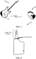
- Fig. 1 is a configuration diagram of the overall electronic musical instrument system according to the present embodiment.
- the transmitter 10 is a portable device that is connected to a portable electronic musical instrument (an electronic guitar 30 in the present embodiment) having a performance operating device and wirelessly transmits a sound signal output from the electronic musical instrument.
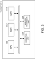
- Fig. 2 is a diagram illustrating an appearance of the transmitter 10. As illustrated, the transmitter 10 may be connected to the electronic musical instrument via a phone plug having a three-pole connection terminal. When the transmitter 10 is inserted into a sound output terminal (phone jack) of the electronic musical instrument, a physical switch (power switch) is turned on, and the transmitter 10 acquires a sound signal from the electronic musical instrument, and wirelessly transmits the sound signal.
- the electronic guitar 30 has a plurality of strings and a pickup that detects vibrations of the strings, detects the vibrations of the strings with the pickup, converts the vibrations into an electrical signal (sound signal), and outputs the signal.
- the electronic guitar 30 outputs the sound signal to the transmitter 10 via the phone jack.
- the output sound signal is modulated and wirelessly transmitted by the transmitter 10 to be received and demodulated by the sound output device 20 that is a headphone device, and is output.
- the transmitter 10 is configured to include a central processing unit (CPU) 101, a ROM 102, a RAM 103, a connection unit 104, and a wireless transmission unit 105. These means are driven by power supplied from a rechargeable type battery (not illustrated).
- CPU central processing unit
- ROM read-only memory
- RAM random access memory
- connection unit 104 connection unit
- wireless transmission unit 105 wireless transmission unit
- the CPU 101 is a calculation device that manages control performed by the transmitter 10.
- the ROM 102 is a rewritable nonvolatile memory.
- the ROM 102 stores a control program executed by the CPU 101 and data (for example, a frequency used for transmitting a musical sound signal) used by the control program.
- the RAM 103 is a memory to which the control program executed by the CPU 101 and the data used by the control program are loaded.
- the program stored in the ROM 102 is loaded to the RAM 103 and executed by the CPU 101 to perform processes described below.
- the configuration illustrated in Fig. 3 is only an example, and all or some of the illustrated functions may be executed by using a dedicated circuit.
- the program may be stored or executed through a combination of a main storage device and an auxiliary storage device other than those illustrated.
- the connection unit 104 is an interface (for example, a two-pole or three-pole phone plug) for physically connecting the transmitter 10 to the electronic guitar 30.
- the connection unit 104 has the connection terminal illustrated in Fig. 2 , and is configured to be able to acquire a sound signal from the electronic guitar 30 when connected to the electronic guitar 30.
- the power switch is disposed near the connection terminal of the connection unit 104, and the power switch is pressed by inserting the plug.
- the wireless transmission unit 105 is a wireless communication interface that wirelessly transmits signals.
- the wireless transmission unit 105 transmits a sound signal output from the electronic guitar 30 to the sound output device 20.
- the respective means are communicatively connected to each other via a bus.
- the sound output device 20 is a headphone type device that amplifies and outputs a sound signal transmitted wirelessly from the transmitter 10.
- the sound output device 20 has (1) a function of performing a predetermined process (such as adding a sound effect) to the received sound signal, amplifying the sound signal, and outputting an amplified result, and (2) a function of tuning an electronic musical instrument on the basis of the received sound signal.
- the two functions may be switched between by an operation performed by an operator.
- the sound output device 20 is configured to include a wireless reception unit 201, a DSP 202, a ROM 203, a RAM 204, an amplifier 205, and a speaker 206. These means are driven by power supplied by a rechargeable type battery.
- the wireless reception unit 201 is a wireless communication interface that receives a signal transmitted from the transmitter 10.
- the wireless reception unit 201 is wirelessly connected to the wireless transmission unit 105 of the transmitter 10, and receives a sound signal output from the electronic guitar 30.
- the DSP 202 is a microprocessor specialized in digital signal processing.
- the DSP 202 performs processing specialized for processing an audio signal. Specifically, a signal acquired via the wireless reception unit 201 is decoded to acquire a sound signal, and an effect is added to the sound signal as necessary. The sound signal output from the DSP 202 is converted into an analog signal that is then amplified by the amplifier 205, and then the analog signal is output from the speaker 206.
- the DSP 202 is configured to be able to execute a tuning process described in the present specification. A specific process will be described later.
- the ROM 203 is a rewritable nonvolatile memory.
- the ROM 203 stores a control program executed by the DSP 202 and data used by the control program.
- the data stored in the ROM 203 may include, for example, a frequency or a channel list when the sound output device 20 and the transmitter 10 perform wireless communication.
- the data may also include information required for tuning (for example, information regarding a reference frequency (that will be described later with reference to Fig. 7 )).
- the RAM 204 is a memory to which the control program executed by the DSP 202 and the data used by the control program are loaded.
- the program stored in the ROM 203 is loaded to the RAM 204 and executed by the DSP 202 to perform processes described below.
- the configuration illustrated in Fig. 4 is only an example, and all or some of the illustrated functions may be executed by using a dedicated circuit.
- the program may be stored or executed through a combination of a main storage device and an auxiliary storage device other than illustrated.
- the DSP 202 is configured to include each of functional blocks such as a musical sound signal input unit 2021, an effector 2022, a determination sound generation unit 2023, a function selecting unit 2024, a volume setting unit 2025, and a sound emitting unit 2026.
- the functional blocks may be realized by the DSP 202 executing corresponding program modules.
- the musical sound signal input unit 2021 acquires a musical sound signal received via the wireless reception unit 201 and decodes the musical sound signal.
- the decoded signal is input to the effector 2022 and the determination sound generation unit 2023.
- a musical sound signal is used to refer to both of an analog signal and a digital signal.
- the effector 2022 adds an effect to the input musical sound signal.
- the effector 2022 has a plurality of effect units built thereinto, and may add predetermined effects such as chorus, phaser, tremolo, and vibrato to the musical sound signal.
- the determination sound generation unit 2023 performs tuning on the basis of the input musical sound signal. Specifically, a frequency (hereinafter, a reference frequency) for comparison is determined on the basis of the input musical sound signal, and a frequency of the musical sound signal is compared with the reference frequency. For example, in a case where it is recognized that the input musical sound signal corresponds to the scale of A4, it is determined that comparison will be performed by using a frequency of 440 Hz, and the two frequencies are compared. On the basis of a result of the comparison, a signal sound (hereinafter, a determination sound) indicating the result of the comparison is generated. In the present embodiment, there are the following three types of determination sounds.
- the function selecting unit 2024 switches between an active/inactive state of the determination sound generation unit 2023.
- the function selecting unit 2024 switches an active/inactive state of the determination sound generation unit 2023 on the basis of an operation performed by an operator by using a switch (not illustrated).
- a determination sound (any of the first to third determination sounds) is generated by the determination sound generation unit 2023.
- the generated determination sound is mixed with a sound signal (hereinafter, an original sound) having passed through the effector 2022 and output.
- the volume setting unit 2025 attenuates the sound signals output from the determination sound generation unit 2023 and the effector 2022 on the basis of the user's operation.
- the sound emitting unit 2026 outputs the sound signal output from the effector 2022 and the sound signal output from the determination sound generation unit 2023.
- the output sound signals are emitted via the amplifier 205 and the speaker 206.
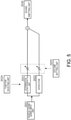
- Fig. 6 is a diagram for describing functional blocks of the determination sound generation unit 2023.
- Fig. 7 is a flowchart illustrating a process performed by the determination sound generation unit 2023 in an active state.
- step S11 it is determined whether or not a musical sound signal has been detected.
- the determination sound generation unit 2023 waits for a musical sound signal to be detected.
- the flow proceeds to step S12, and a frequency f1 corresponding to the musical sound signal and a reference frequency fb for comparison are determined.
- a reference frequency determination portion 32 estimates an original scale of the musical sound signal.
- the musical sound signal is subjected to Fourier transform to extract frequency components, and the frequency f1 corresponding to the musical sound signal is specified on the basis of the extracted frequency components.
- a principal frequency may be specified according to a predetermined method.
- a pitch is estimated on the basis of the specified frequency.
- Fig. 8 illustrates an example of data (hereinafter, frequency data) for determining a reference frequency by using a frequency corresponding to a musical sound signal. A pitch closest to the musical sound signal can be estimated by referring to the frequency data as illustrated.
- the reference frequency fb corresponding to the estimated pitch is determined. For example, in a case where the estimated pitch is A4, 440 Hz is selected as the reference frequency.
- the frequency data illustrated in Fig. 8 may be stored in advance in the ROM 203.
- the scale is set to one octave, but the frequency data is not limited to this.
- a tuning target is a piano
- frequency data in which pitches and frequencies corresponding to 88 strings are associated with each other may be used.
- a tuning target is a double bass
- frequency data in which pitches and frequencies corresponding to four strings are associated with each other may be used.
- a tuning target is a guitar
- frequency data in which pitches and frequencies corresponding to six strings are associated with each other may be used.
- a plurality of pieces of frequency data may be stored.
- the reference frequency determination portion 32 may select frequency data to be used on the basis of an instruction from the operator.
- a connected musical instrument may be automatically determined, and frequency data to be used may then be selected.
- a comparison portion 31 compares the frequency of the musical sound signal with the reference frequency, and classifies a comparison result into three patterns such as "lower”, “substantially the same", and “higher” (step S13).
- Substantially the same range may be set to a design value, but is preferably set to a range in which tuning is considered to be musically established.
- step S14A a selecting portion 33 selects a first determination sound generation portion 34, and the first determination sound generation portion 34 generates the first determination sound.
- step S14C the flow proceeds to step S14C such that the second determination sound is generated and output.
- the selecting portion 33 selects a second determination sound generation portion 35, and the second determination sound generation portion 35 generates the second determination sound.
- step S14B the flow proceeds to step S14B such that the third determination sound is generated and output.
- the selecting portion 33 selects a third determination sound generation portion 36, and the third determination sound generation portion 36 generates the third determination sound.
- step S15 standby is performed for a predetermined time, and then the flow proceeds to step S11. Consequently, a determination sound can be intermittently output.
- the first determination sound is preferably a sound from which it can be intuitively understood that a frequency of a currently emitted sound is lower than the reference frequency.
- a frequency of a currently emitted sound is lower than the reference frequency.
- two types of beep sounds having different pitches in the order of low to high are output, and thus it is possible to transfer to the operator that a pitch is to be raised.
- the second determination sound is preferably a sound from which it can be intuitively understood that a frequency of a currently emitted sound is higher than the reference frequency.
- a frequency of a currently emitted sound is higher than the reference frequency.
- two types of beep sounds having different pitches in the order of high to low are output, and thus it is possible to transfer to the operator that a pitch is to be lowered.
- a combination of pitches of the determination sounds is not limited to the examples.
- the determination sound does not have to be a combination of independent beep sounds.
- a sound (sweep sound) of which a pitch changes continuously is output, and thus it is possible to transfer a direction in which adjustment is to be performed (whether the pitch is to be adjusted to be raised or lowered).
- the pitch of the sweep sound changes in proportion to time, but a rate of change is not limited to a linear function.
- the pitch may change exponentially with time, such as an exponential chirp. According to such a configuration, it is possible to give the operator the impression that the pitch goes up and down linearly.
- the third determination sound is preferably a sound from which it can be intuitively understood that a frequency of a currently emitted sound is substantially the same as the reference frequency. For example, a beep sound of which a pitch does not change is output, and thus it is possible to transfer to the operator that tuning has been completed.
- an emission interval (first cycle) of a determination sound is changed with the predetermined time in step S15.
- the tuning device outputs different determination sounds on the basis of a result of comparing a frequency of a musical sound signal acquired from a musical instrument with the reference frequency. According to such an aspect, it is possible to intuitively understand a direction in which adjustment is to be performed (whether a pitch is to be adjusted to be raised or lowered).
- the tuning device according to the present embodiment can be suitably applied to tuning of a musical instrument of which a pitch can be continuously adjusted according to, for example, an amount of operation.
- a stringed instrument such as a guitar, a double bass, or a piano, particularly an instrument having pegs for adjusting tension of strings
- the tuning device according to the present embodiment can report a status only by sound, and thus an operator can concentrate on work.
- a second embodiment is an embodiment in which the predetermined time in step S15 is variable.
- a hardware configuration of the sound output device 20 according to the second embodiment is the same as that in the first embodiment except processes executed by the determination sound generation unit 2023.
- the determination sound generation unit 2023 determines the predetermined time in step S15, that is, a sound emission interval of a determination sound on the basis of a "deviation width between a frequency of a musical sound signal and the reference frequency".
- Fig. 9 is a diagram for describing a sound emission interval of a determination sound.
- control is performed such that a sound emission interval becomes longer.
- a relationship between the deviation width and the sound emission interval can be defined as illustrated in Fig. 10 , for example.
- Such data may be stored in the ROM 203 in advance.
- an operator can be notified by sound of the magnitude of a difference between a frequency of a musical sound signal and the reference frequency. Consequently, the operator can easily understand a width to be adjusted.
- control is performed such that a sound emission interval becomes longer as a deviation width becomes larger, but the control may be performed such that the sound emission interval becomes shorter as the deviation width becomes larger. That is, the sound emission interval may be correlated with a difference between the frequency of the musical sound signal and the reference frequency.
- a third embodiment is an embodiment in which a sound signal indicating a reference frequency is output in addition to a determination sound.
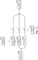
- Fig. 11 is a functional block diagram of the sound output device 20 (DSP 202) according to the third embodiment.
- the DSP 202 is configured to further include a reference sound generation unit 2027.
- the reference sound generation unit 2027 generates a sound signal (hereinafter, a reference sound; for example, a sine wave) corresponding to a reference frequency determined by the determination sound generation unit 2023.
- the reference sound is mixed with a determination sound and an original sound to be output via the sound emitting unit 2026.
- the function selecting unit 2024 is configured such that an active state of the determination sound generation unit 2023 and an active state of the reference sound generation unit 2027 are switched simultaneously or separately. For example, selection may be made such as “only the determination sound generation unit 2023 is in an active state” and "the determination sound generation unit 2023 and the reference sound generation unit 2027 are in an active state”.
- the third embodiment since an operator can hear an original sound and a reference sound at the same time, it becomes easier to understand a direction in which adjustment is to be performed.
- the tuning device according to the present invention may be a device connected in a wired manner.
- a tuning target does not necessarily have to be an electronic musical instrument, and may be any musical instrument as long as the musical instrument outputs an audio signal.
- standby is performed for the predetermined time in step S15, but in a case where new rising (attack) of a musical sound signal is detected during the standby, the standby may be interrupted and the determination in step S13 may be started immediately.
- Arising timing of the musical sound signal may be, for example, a timing at which a level of the musical sound signal exceeds a predetermined value.
Landscapes
- Engineering & Computer Science (AREA)
- Physics & Mathematics (AREA)
- Acoustics & Sound (AREA)
- Multimedia (AREA)
- Signal Processing (AREA)
- Auxiliary Devices For Music (AREA)
Abstract
Description
- The present invention relates to a technique of tuning a musical instrument.
- In the musical instrument field, there is a device that performs tuning on the basis of a musical sound signal output from a musical instrument. For example,
Patent Literatures 1 and 2 disclose a device that visually displays to what extent a frequency of sound output from a target musical instrument deviates relative to a frequency of a reference sound. -
- [Patent Literature 1]
Japanese Patent Laid-Open No. 2009-86443 - [Patent Literature 2]
Japanese Patent Laid-Open No. 2004-53779 - According to the invention disclosed in
Patent Literatures 1 and 2, a tuning status of an electronic musical instrument can be intuitively understood. On the other hand, in this invention, since a status is reported by using a light emitting element or a liquid crystal screen, an operator needs to always pay attention to the device during tuning work in order to ascertain a hierarchical pitch relationship between a sound output from a musical instrument and a reference sound. That is, there is a problem in that usability is reduced. - The present invention has been made in view of this problem, and an objective thereof is to provide a technique for intuitively reporting a difference between a pitch of a sound output from a musical instrument and a pitch of a reference sound.
- According to the present invention, there is provided a tuning device including a signal acquisition means for acquiring an audio signal, a comparison means for comparing a frequency of the audio signal with a reference frequency corresponding to the audio signal, and a generation means for generating a first sound signal in a case where the frequency of the audio signal is lower than the reference frequency and generating a second sound signal different from the first sound signal in a case where the frequency of the audio signal is higher than the reference frequency.
- The tuning device according to the present invention determines a hierarchical relationship between a frequency of an audio signal (for example, a musical sound signal acquired from an electronic musical instrument) and a reference frequency corresponding to the audio signal, and changes a sound signal to be generated on the basis of the hierarchical relationship.
- According to this configuration, since it is possible to notify an operator of the hierarchical relationship between the frequency of the audio signal and the reference frequency only by sound, it is not necessary to always pay attention to the device, and thus usability can be improved.
- In the present specification, the frequency of the audio signal is a frequency corresponding to a sound (for example, representing a sound) included in the audio signal, and is a frequency obtained by evaluating the audio signal according to any evaluation method. Therefore, the audio signal does not necessarily have to include only a single frequency component.
- The first and second sound signals may be sound signals generated in a first cycle, and the first cycle may be a value correlated with a difference between the frequency of the audio signal and the reference frequency.
- According to this configuration, in addition to a hierarchical relationship between frequencies, it is possible to report by sound how wide a difference between the frequencies is (how much the deviation width is).
- In a case where the signal acquisition means has detected rising of the audio signal, the generation means may reset counting of the first cycle and immediately start to generate the first sound signal or the second sound signal.
- For example, in a case where the audio signal is a musical sound signal output from an electronic musical instrument, the first cycle is reset and a sound signal is immediately generated when the operator hits a key or performs picking, and thus it is possible to transfer the current status to an operator more quickly. A rising timing of the audio signal may be, for example, a timing at which a level of the audio signal exceeds a predetermined value.
- The first and second sound signals may be a combination of two or more sounds having different pitches, and the pitches may have opposite combinations in the first sound signal and the second sound signal.
- For example, a combination of sounds having different pitches such as "high to low" and "low to high" is provided, and thus it is possible to intuitively report whether the frequency of the audio signal is lower or higher than the reference frequency.
- Each of the sounds having different pitches does not necessarily have to be a single sound, and may change smoothly.
- For example, the first and second sound signals may be sweep sounds in which two or more sounds having different pitches are continuously connected to each other, and are preferably exponential chirp signals. In this case, a pitch changes exponentially, and thus it is possible to report a vertical direction in an easy-to-understand manner.
- In a case where the frequency of the audio signal is substantially the same as the reference frequency, the generation means may generate a third sound signal different from the first and second sound signals.
- According to this configuration, it is possible to notify an operator by sound that a pitch has reached an ideal state.
- The tuning device may further include an effect adding means for adding a predetermined effect to the audio signal, and the generation means may mix the audio signal to which an effect has been added with the first sound signal or the second sound signal.
- The audio signal for reporting a tuning status and the audio signal to which a predetermined effect has been added are mixed, and thus an operator can understand a tuning target sound.
- According to another aspect of the present invention, there is provided a tuning device including a signal acquisition means for acquiring an audio signal, a comparison means for comparing a frequency of the audio signal with a reference frequency corresponding to the audio signal, and a generation means for generating a sound signal in a first cycle in a case where the frequency of the audio signal is not substantially the same as the reference frequency, in which the first cycle is a value correlated with a difference between the frequency of the audio signal and the reference frequency.
- As described above, the present invention may also be specified as a device for reporting the magnitude of a frequency deviation width by sound.
- The signal acquisition means may acquire the audio signal from a musical instrument that is capable of continuously adjusting a pitch according to an amount of tuning operation.
- The present invention may be specified as a tuning device including at least some of the above means. The present invention may also be specified as a method performed by the tuning device. The present invention may also be specified as a program for executing the method. The above processes or means may be freely combined and implemented as long as there are no technical contradictions therebetween.
-
-
Fig. 1 is a configuration diagram of an electronic musical instrument system according to an embodiment. -
Fig. 2 is an appearance diagram of a transmitter. -
Fig. 3 is a hardware configuration diagram of the transmitter. -
Fig. 4 is a hardware configuration diagram of a sound output device. -
Fig. 5 is a functional configuration diagram of a DSP (Digital Signal Processor) of a sound output device according to a first embodiment. -
Fig. 6 is a functional configuration diagram of a determination sound generation unit. -
Fig. 7 is a flowchart illustrating a process performed by the sound output device. -
Fig. 8 illustrates an example of a table for specifying a pitch from a frequency. -
Fig. 9 is a diagram for describing a relationship between a deviation width and a sound emission interval. -
Fig. 10 is a diagram for describing a relationship between a deviation width and a sound emission interval. -
Fig. 11 is a functional configuration diagram of a DSP of a sound output device according to a third embodiment. - An electronic musical instrument system according to the present embodiment is configured to include a
transmitter 10 that wirelessly transmits a sound signal output from an electronic musical instrument and asound output device 20 that receives and amplifies the wirelessly transmitted sound signal and outputs an amplified result. -
Fig. 1 is a configuration diagram of the overall electronic musical instrument system according to the present embodiment. - The
transmitter 10 is a portable device that is connected to a portable electronic musical instrument (anelectronic guitar 30 in the present embodiment) having a performance operating device and wirelessly transmits a sound signal output from the electronic musical instrument.Fig. 2 is a diagram illustrating an appearance of thetransmitter 10. As illustrated, thetransmitter 10 may be connected to the electronic musical instrument via a phone plug having a three-pole connection terminal. When thetransmitter 10 is inserted into a sound output terminal (phone jack) of the electronic musical instrument, a physical switch (power switch) is turned on, and thetransmitter 10 acquires a sound signal from the electronic musical instrument, and wirelessly transmits the sound signal. - The
electronic guitar 30 has a plurality of strings and a pickup that detects vibrations of the strings, detects the vibrations of the strings with the pickup, converts the vibrations into an electrical signal (sound signal), and outputs the signal. Theelectronic guitar 30 outputs the sound signal to thetransmitter 10 via the phone jack. The output sound signal is modulated and wirelessly transmitted by thetransmitter 10 to be received and demodulated by thesound output device 20 that is a headphone device, and is output. - With reference to
Fig. 3 , a hardware configuration of thetransmitter 10 will be described. - The
transmitter 10 is configured to include a central processing unit (CPU) 101, aROM 102, aRAM 103, aconnection unit 104, and awireless transmission unit 105. These means are driven by power supplied from a rechargeable type battery (not illustrated). - The
CPU 101 is a calculation device that manages control performed by thetransmitter 10. - The
ROM 102 is a rewritable nonvolatile memory. TheROM 102 stores a control program executed by theCPU 101 and data (for example, a frequency used for transmitting a musical sound signal) used by the control program. - The
RAM 103 is a memory to which the control program executed by theCPU 101 and the data used by the control program are loaded. The program stored in theROM 102 is loaded to theRAM 103 and executed by theCPU 101 to perform processes described below. - The configuration illustrated in
Fig. 3 is only an example, and all or some of the illustrated functions may be executed by using a dedicated circuit. The program may be stored or executed through a combination of a main storage device and an auxiliary storage device other than those illustrated. - The
connection unit 104 is an interface (for example, a two-pole or three-pole phone plug) for physically connecting thetransmitter 10 to theelectronic guitar 30. Theconnection unit 104 has the connection terminal illustrated inFig. 2 , and is configured to be able to acquire a sound signal from theelectronic guitar 30 when connected to theelectronic guitar 30. - The power switch is disposed near the connection terminal of the
connection unit 104, and the power switch is pressed by inserting the plug. - The
wireless transmission unit 105 is a wireless communication interface that wirelessly transmits signals. In the present embodiment, thewireless transmission unit 105 transmits a sound signal output from theelectronic guitar 30 to thesound output device 20. - The respective means are communicatively connected to each other via a bus.
- Next, a hardware configuration of the
sound output device 20 will be described with reference toFig. 4 . - The
sound output device 20 is a headphone type device that amplifies and outputs a sound signal transmitted wirelessly from thetransmitter 10. Thesound output device 20 has (1) a function of performing a predetermined process (such as adding a sound effect) to the received sound signal, amplifying the sound signal, and outputting an amplified result, and (2) a function of tuning an electronic musical instrument on the basis of the received sound signal. - The two functions may be switched between by an operation performed by an operator.
- The
sound output device 20 is configured to include awireless reception unit 201, aDSP 202, aROM 203, aRAM 204, anamplifier 205, and aspeaker 206. These means are driven by power supplied by a rechargeable type battery. - The
wireless reception unit 201 is a wireless communication interface that receives a signal transmitted from thetransmitter 10. In the present embodiment, thewireless reception unit 201 is wirelessly connected to thewireless transmission unit 105 of thetransmitter 10, and receives a sound signal output from theelectronic guitar 30. - The
DSP 202 is a microprocessor specialized in digital signal processing. In the present embodiment, theDSP 202 performs processing specialized for processing an audio signal. Specifically, a signal acquired via thewireless reception unit 201 is decoded to acquire a sound signal, and an effect is added to the sound signal as necessary. The sound signal output from theDSP 202 is converted into an analog signal that is then amplified by theamplifier 205, and then the analog signal is output from thespeaker 206. - The
DSP 202 is configured to be able to execute a tuning process described in the present specification. A specific process will be described later. - The
ROM 203 is a rewritable nonvolatile memory. TheROM 203 stores a control program executed by theDSP 202 and data used by the control program. The data stored in theROM 203 may include, for example, a frequency or a channel list when thesound output device 20 and thetransmitter 10 perform wireless communication. The data may also include information required for tuning (for example, information regarding a reference frequency (that will be described later with reference toFig. 7 )). - The
RAM 204 is a memory to which the control program executed by theDSP 202 and the data used by the control program are loaded. The program stored in theROM 203 is loaded to theRAM 204 and executed by theDSP 202 to perform processes described below. - The configuration illustrated in
Fig. 4 is only an example, and all or some of the illustrated functions may be executed by using a dedicated circuit. The program may be stored or executed through a combination of a main storage device and an auxiliary storage device other than illustrated. - Next, with reference to
Fig. 5 , a functional block of theDSP 202 will be described. - The
DSP 202 is configured to include each of functional blocks such as a musical soundsignal input unit 2021, aneffector 2022, a determinationsound generation unit 2023, afunction selecting unit 2024, avolume setting unit 2025, and asound emitting unit 2026. The functional blocks may be realized by theDSP 202 executing corresponding program modules. - The musical sound
signal input unit 2021 acquires a musical sound signal received via thewireless reception unit 201 and decodes the musical sound signal. The decoded signal is input to theeffector 2022 and the determinationsound generation unit 2023. In the following description, a musical sound signal is used to refer to both of an analog signal and a digital signal. - The
effector 2022 adds an effect to the input musical sound signal. Theeffector 2022 has a plurality of effect units built thereinto, and may add predetermined effects such as chorus, phaser, tremolo, and vibrato to the musical sound signal. - The determination
sound generation unit 2023 performs tuning on the basis of the input musical sound signal. Specifically, a frequency (hereinafter, a reference frequency) for comparison is determined on the basis of the input musical sound signal, and a frequency of the musical sound signal is compared with the reference frequency. For example, in a case where it is recognized that the input musical sound signal corresponds to the scale of A4, it is determined that comparison will be performed by using a frequency of 440 Hz, and the two frequencies are compared. On the basis of a result of the comparison, a signal sound (hereinafter, a determination sound) indicating the result of the comparison is generated. In the present embodiment, there are the following three types of determination sounds. - (1) A determination sound indicating that the frequency of the musical sound signal is lower than the reference frequency (first determination sound)
- (2) A determination sound indicating that the frequency of the musical sound signal is higher than the reference frequency (second determination sound)
- (3) A determination sound indicating that the frequency of the musical sound signal is substantially the same as the reference frequency (third determination sound)
- The
function selecting unit 2024 switches between an active/inactive state of the determinationsound generation unit 2023. Thefunction selecting unit 2024 switches an active/inactive state of the determinationsound generation unit 2023 on the basis of an operation performed by an operator by using a switch (not illustrated). - Here, in a case where the determination
sound generation unit 2023 is brought into an active state, that is, a tuning function is selected to be validated, as described above, a determination sound (any of the first to third determination sounds) is generated by the determinationsound generation unit 2023. The generated determination sound is mixed with a sound signal (hereinafter, an original sound) having passed through theeffector 2022 and output. - On the other hand, in a case where the determination
sound generation unit 2023 is brought into an inactive state, that is, the tuning function is selected to be invalidated, a process using the determinationsound generation unit 2023 is not performed. In this case, only a sound signal (original sound) having passed through theeffector 2022 is output. - The
volume setting unit 2025 attenuates the sound signals output from the determinationsound generation unit 2023 and theeffector 2022 on the basis of the user's operation. - The
sound emitting unit 2026 outputs the sound signal output from theeffector 2022 and the sound signal output from the determinationsound generation unit 2023. The output sound signals are emitted via theamplifier 205 and thespeaker 206. - Next, a process performed by the determination
sound generation unit 2023 will be described with reference toFigs. 6 and7 . -
Fig. 6 is a diagram for describing functional blocks of the determinationsound generation unit 2023.Fig. 7 is a flowchart illustrating a process performed by the determinationsound generation unit 2023 in an active state. - First, in step S11, it is determined whether or not a musical sound signal has been detected. Here, in a case where a determination result is negative (for example, in a case where a signal level is equal to or less than a predetermined value), the determination
sound generation unit 2023 waits for a musical sound signal to be detected. In a case where a determination result is affirmative in step S11, the flow proceeds to step S12, and a frequency f1 corresponding to the musical sound signal and a reference frequency fb for comparison are determined. - In step S12, first, a reference
frequency determination portion 32 estimates an original scale of the musical sound signal. For example, the musical sound signal is subjected to Fourier transform to extract frequency components, and the frequency f1 corresponding to the musical sound signal is specified on the basis of the extracted frequency components. In a case where there are frequency components of a plurality of peaks, a principal frequency may be specified according to a predetermined method. - Next, a pitch is estimated on the basis of the specified frequency.
Fig. 8 illustrates an example of data (hereinafter, frequency data) for determining a reference frequency by using a frequency corresponding to a musical sound signal. A pitch closest to the musical sound signal can be estimated by referring to the frequency data as illustrated. - The reference frequency fb corresponding to the estimated pitch is determined. For example, in a case where the estimated pitch is A4, 440 Hz is selected as the reference frequency.
- The frequency data illustrated in
Fig. 8 may be stored in advance in theROM 203. - In the example in
Fig. 8 , the scale is set to one octave, but the frequency data is not limited to this. For example, in a case where a tuning target is a piano, frequency data in which pitches and frequencies corresponding to 88 strings are associated with each other may be used. In a case where a tuning target is a double bass, frequency data in which pitches and frequencies corresponding to four strings are associated with each other may be used. In a case where a tuning target is a guitar, frequency data in which pitches and frequencies corresponding to six strings are associated with each other may be used. - A plurality of pieces of frequency data may be stored. In a case where a plurality of pieces of frequency data are used, the reference
frequency determination portion 32 may select frequency data to be used on the basis of an instruction from the operator. A connected musical instrument may be automatically determined, and frequency data to be used may then be selected. - Next, a
comparison portion 31 compares the frequency of the musical sound signal with the reference frequency, and classifies a comparison result into three patterns such as "lower", "substantially the same", and "higher" (step S13). Substantially the same range may be set to a design value, but is preferably set to a range in which tuning is considered to be musically established. - In a case where the frequency of the musical sound signal is lower than the reference frequency (or a predetermined range set on the basis of the reference frequency), the flow proceeds to step S14A such that the first determination sound is generated and output. In step S14A, a selecting
portion 33 selects a first determinationsound generation portion 34, and the first determinationsound generation portion 34 generates the first determination sound. - In a case where the frequency of the musical sound signal is higher than the reference frequency (or a predetermined range set on the basis of the reference frequency), the flow proceeds to step S14C such that the second determination sound is generated and output. In step S14C, the selecting
portion 33 selects a second determinationsound generation portion 35, and the second determinationsound generation portion 35 generates the second determination sound. - In a case where the frequency of the musical sound signal is substantially the same as the reference frequency (or within a predetermined range set on the basis of the reference frequency), the flow proceeds to step S14B such that the third determination sound is generated and output. In step S14B, the selecting
portion 33 selects a third determinationsound generation portion 36, and the third determinationsound generation portion 36 generates the third determination sound. - In step S15, standby is performed for a predetermined time, and then the flow proceeds to step S11. Consequently, a determination sound can be intermittently output.
- Here, a determination sound will be described.
- The first determination sound is preferably a sound from which it can be intuitively understood that a frequency of a currently emitted sound is lower than the reference frequency. For example, two types of beep sounds having different pitches in the order of low to high are output, and thus it is possible to transfer to the operator that a pitch is to be raised.
- The second determination sound is preferably a sound from which it can be intuitively understood that a frequency of a currently emitted sound is higher than the reference frequency. For example, two types of beep sounds having different pitches in the order of high to low are output, and thus it is possible to transfer to the operator that a pitch is to be lowered.
- (An example of the first determination sound) popi ... popi ... popi ... (po represents a low pitch, and pi represents a high pitch)
- (An example of the second determination sound) pipo ... pipo ... pipo ... (same)
- A combination of pitches of the determination sounds is not limited to the examples.
- The determination sound does not have to be a combination of independent beep sounds. For example, a sound (sweep sound) of which a pitch changes continuously is output, and thus it is possible to transfer a direction in which adjustment is to be performed (whether the pitch is to be adjusted to be raised or lowered). The pitch of the sweep sound changes in proportion to time, but a rate of change is not limited to a linear function. For example, the pitch may change exponentially with time, such as an exponential chirp. According to such a configuration, it is possible to give the operator the impression that the pitch goes up and down linearly.
- The third determination sound is preferably a sound from which it can be intuitively understood that a frequency of a currently emitted sound is substantially the same as the reference frequency. For example, a beep sound of which a pitch does not change is output, and thus it is possible to transfer to the operator that tuning has been completed.
- (An example of the third determination sound) pipi ... pipi ... pipi ...
- In the above-described example, an emission interval (first cycle) of a determination sound is changed with the predetermined time in step S15.
- As described above, the tuning device according to the present embodiment outputs different determination sounds on the basis of a result of comparing a frequency of a musical sound signal acquired from a musical instrument with the reference frequency. According to such an aspect, it is possible to intuitively understand a direction in which adjustment is to be performed (whether a pitch is to be adjusted to be raised or lowered).
- Since a musical sound signal that has passed through the effector and a determination sound are mixed and output, it is possible to perform tuning while hearing actually obtained performance sounds.
- The tuning device according to the present embodiment can be suitably applied to tuning of a musical instrument of which a pitch can be continuously adjusted according to, for example, an amount of operation. For example, when tuning a stringed instrument such as a guitar, a double bass, or a piano, particularly an instrument having pegs for adjusting tension of strings, it is preferable to observe states of the pegs or the strings one by one during work, but in a case where information is given visually as in the related art, an operator cannot concentrate on a state of the instrument. On the other hand, the tuning device according to the present embodiment can report a status only by sound, and thus an operator can concentrate on work.
- A second embodiment is an embodiment in which the predetermined time in step S15 is variable. A hardware configuration of the
sound output device 20 according to the second embodiment is the same as that in the first embodiment except processes executed by the determinationsound generation unit 2023. - In the second embodiment, the determination
sound generation unit 2023 determines the predetermined time in step S15, that is, a sound emission interval of a determination sound on the basis of a "deviation width between a frequency of a musical sound signal and the reference frequency". -
Fig. 9 is a diagram for describing a sound emission interval of a determination sound. In the present embodiment, in a case where a difference (deviation width) between the frequency of the musical sound signal and the reference frequency is large, control is performed such that a sound emission interval becomes longer. A relationship between the deviation width and the sound emission interval can be defined as illustrated inFig. 10 , for example. Such data may be stored in theROM 203 in advance. - According to the second embodiment, an operator can be notified by sound of the magnitude of a difference between a frequency of a musical sound signal and the reference frequency. Consequently, the operator can easily understand a width to be adjusted.
- In the present embodiment, control is performed such that a sound emission interval becomes longer as a deviation width becomes larger, but the control may be performed such that the sound emission interval becomes shorter as the deviation width becomes larger. That is, the sound emission interval may be correlated with a difference between the frequency of the musical sound signal and the reference frequency.
- A third embodiment is an embodiment in which a sound signal indicating a reference frequency is output in addition to a determination sound.
Fig. 11 is a functional block diagram of the sound output device 20 (DSP 202) according to the third embodiment. - In the third embodiment, the
DSP 202 is configured to further include a referencesound generation unit 2027. The referencesound generation unit 2027 generates a sound signal (hereinafter, a reference sound; for example, a sine wave) corresponding to a reference frequency determined by the determinationsound generation unit 2023. The reference sound is mixed with a determination sound and an original sound to be output via thesound emitting unit 2026. - In the third embodiment, the
function selecting unit 2024 is configured such that an active state of the determinationsound generation unit 2023 and an active state of the referencesound generation unit 2027 are switched simultaneously or separately. For example, selection may be made such as "only the determinationsound generation unit 2023 is in an active state" and "the determinationsound generation unit 2023 and the referencesound generation unit 2027 are in an active state". - According to the third embodiment, since an operator can hear an original sound and a reference sound at the same time, it becomes easier to understand a direction in which adjustment is to be performed.
- The embodiments are only examples, and the present invention may be modified and implemented as appropriate without departing from the spirit thereof. For example, the respective embodiments may be combined and implemented.
- In the description of the embodiments, the
sound output device 20 connected in a wireless manner has been described, but the tuning device according to the present invention may be a device connected in a wired manner. - A tuning target does not necessarily have to be an electronic musical instrument, and may be any musical instrument as long as the musical instrument outputs an audio signal.
- In the description of the embodiments, standby is performed for the predetermined time in step S15, but in a case where new rising (attack) of a musical sound signal is detected during the standby, the standby may be interrupted and the determination in step S13 may be started immediately. Arising timing of the musical sound signal may be, for example, a timing at which a level of the musical sound signal exceeds a predetermined value.
- According to such a configuration, in a case where an operator hits a key or performs picking, a determination sound is immediately output, and thus a deviation width can be reported more quickly and intuitively.
-
- 10
- Transmitter
- 20
- Sound output device
- 30
- Electronic guitar
- 101
- CPU
- 102, 203
- ROM
- 103, 204
- RAM
- 104
- Connection unit
- 105
- Wireless transmission unit
- 201
- Wireless reception unit
- 202
- DSP
- 205
- Amplifier
- 206
- Speaker
Claims (15)
- A tuning device comprising:a signal acquisition means for acquiring an audio signal;a comparison means for comparing a frequency of the audio signal with a reference frequency corresponding to the audio signal; anda generation means for generating a first sound signal in a case where the frequency of the audio signal is lower than the reference frequency and generating a second sound signal different from the first sound signal in a case where the frequency of the audio signal is higher than the reference frequency.
- The tuning device according to claim 1,wherein the first and second sound signals are sound signals generated in a first cycle, andwherein the first cycle is a value correlated with a difference between the frequency of the audio signal and the reference frequency.
- The tuning device according to claim 2,
wherein, in a case where the signal acquisition means has detected rising of the audio signal, the generation means resets counting of the first cycle and immediately starts to generate the first sound signal or the second sound signal. - The tuning device according to any one of claims 1 to 3,wherein the first and second sound signals are a combination of two or more sounds having different pitches, andwherein the pitches have opposite combinations in the first sound signal and the second sound signal.
- The tuning device according to claim 4,
wherein the first and second sound signals are sweep sounds in which two or more sounds having different pitches are continuously connected to each other. - The tuning device according to any one of claims 1 to 5,
wherein, in a case where the frequency of the audio signal is substantially the same as the reference frequency, the generation means generates a third sound signal different from the first and second sound signals. - The tuning device according to any one of claims 1 to 6, further comprising:an effect adding means for adding a predetermined effect to the audio signal,wherein the generation means mixes the audio signal to which an effect has been added with the first sound signal or the second sound signal.
- A tuning device comprising:a signal acquisition means for acquiring an audio signal;a comparison means for comparing a frequency of the audio signal with a reference frequency corresponding to the audio signal; anda generation means for generating a sound signal in a first cycle in a case where the frequency of the audio signal is not substantially the same as the reference frequency,wherein the first cycle is a value correlated with a difference between the frequency of the audio signal and the reference frequency.
- The tuning device according to claim 8,
wherein the generation means generates a first sound signal in a case where the frequency of the audio signal is lower than the reference frequency and generates a second sound signal different from the first sound signal in a case where the frequency of the audio signal is higher than the reference frequency. - The tuning device according to claim 9,wherein the first and second sound signals are a combination of two or more sounds having different pitches, andwherein the pitches have opposite combinations in the first sound signal and the second sound signal.
- The tuning device according to claim 10,
wherein the first and second sound signals are sweep sounds in which two or more sounds having different pitches are continuously connected to each other. - The tuning device according to any one of claims 9 to 11,
wherein, in a case where the signal acquisition means has detected rising of the audio signal, the generation means resets counting of the first cycle and immediately starts to generate the first sound signal or the second sound signal. - The tuning device according to any one of claims 9 to 12,
wherein, in a case where the frequency of the audio signal is substantially the same as the reference frequency, the generation means generates a third sound signal different from the first and second sound signals. - The tuning device according to any one of claims 8 to 13, further comprising:an effect adding means for adding a predetermined effect to the audio signal,wherein the generation means mixes the audio signal to which an effect has been added with the first sound signal or the second sound signal.
- The tuning device according to any one of claims 1 to 14,
wherein the signal acquisition means acquires the audio signal from a musical instrument that is capable of continuously adjusting a pitch according to an amount of tuning operation.
Applications Claiming Priority (1)
| Application Number | Priority Date | Filing Date | Title |
|---|---|---|---|
| PCT/JP2019/018058 WO2020217489A1 (en) | 2019-04-26 | 2019-04-26 | Tuning device |
Publications (3)
| Publication Number | Publication Date |
|---|---|
| EP3961616A1 true EP3961616A1 (en) | 2022-03-02 |
| EP3961616A4 EP3961616A4 (en) | 2023-03-22 |
| EP3961616B1 EP3961616B1 (en) | 2025-06-04 |
Family
ID=72940901
Family Applications (1)
| Application Number | Title | Priority Date | Filing Date |
|---|---|---|---|
| EP19925961.5A Active EP3961616B1 (en) | 2019-04-26 | 2019-04-26 | Tuning device |
Country Status (5)
| Country | Link |
|---|---|
| US (1) | US11804201B2 (en) |
| EP (1) | EP3961616B1 (en) |
| JP (1) | JP7202454B2 (en) |
| CN (1) | CN113728377B (en) |
| WO (1) | WO2020217489A1 (en) |
Families Citing this family (2)
| Publication number | Priority date | Publication date | Assignee | Title |
|---|---|---|---|---|
| EP3961616B1 (en) * | 2019-04-26 | 2025-06-04 | Roland Corporation | Tuning device |
| JP7730080B2 (en) * | 2020-12-08 | 2025-08-27 | ヤマハ株式会社 | Sound generating device, method and program |
Family Cites Families (29)
| Publication number | Priority date | Publication date | Assignee | Title |
|---|---|---|---|---|
| US4122751A (en) | 1977-04-08 | 1978-10-31 | Calvin Noel M | Automatic instrument tuner |
| US4281577A (en) * | 1979-05-21 | 1981-08-04 | Peter Middleton | Electronic tuning device |
| JPS56162081A (en) * | 1980-05-20 | 1981-12-12 | Ricoh Elemex Corp | Electronic timepiece |
| JPS6365097A (en) | 1986-09-04 | 1988-03-23 | Kawasaki Steel Corp | Zinc alloy electroplated steel sheet having superior plating adhesion after coating and corrosion resistance |
| JPS6389897A (en) * | 1986-10-03 | 1988-04-20 | セイコーインスツルメンツ株式会社 | Tuner with sound judgment |
| JPH0524958Y2 (en) * | 1986-10-15 | 1993-06-24 | ||
| JP2000046407A (en) | 1998-07-29 | 2000-02-18 | Nippon Seiki Co Ltd | Confirmation sound generator |
| JP4125559B2 (en) | 2002-07-18 | 2008-07-30 | ローランド株式会社 | Electronic tuner |
| JP2005017995A (en) | 2003-06-23 | 2005-01-20 | Ric:Kk | Tuning device |
| JP3826177B2 (en) | 2003-09-12 | 2006-09-27 | 株式会社創成電子 | Tuning support device |
| JP4343780B2 (en) * | 2004-06-23 | 2009-10-14 | セイコーインスツル株式会社 | Tuning device, tuning method |
| JP2006220882A (en) | 2005-02-10 | 2006-08-24 | Katsufumi Hashimitsu | Tuning program and recording medium |
| JP2007094220A (en) | 2005-09-30 | 2007-04-12 | Morioka Seiko Instruments Inc | Electronic tuner device |
| JP5156885B2 (en) | 2007-10-01 | 2013-03-06 | 株式会社コルグ | Tuning display, tuning display method, tuning display program and recording medium thereof |
| KR20090130630A (en) * | 2008-06-16 | 2009-12-24 | 허남웅 | Speech practice aid using frequency comparison method |
| US20120240749A1 (en) | 2011-03-25 | 2012-09-27 | John Eric Bjornson | Instrument Tuner for Drums |
| KR20130051386A (en) | 2011-11-09 | 2013-05-20 | 차희찬 | Tuner providing method for instruments using smart device |
| JP2013242440A (en) * | 2012-05-21 | 2013-12-05 | Korg Inc | Tuner |
| US9012757B2 (en) * | 2012-08-22 | 2015-04-21 | David Hirshberg | Synthesized signal tuner |
| JP6225818B2 (en) * | 2014-04-30 | 2017-11-08 | ヤマハ株式会社 | Pitch information generation apparatus, pitch information generation method, and program |
| US20160225356A1 (en) * | 2015-01-30 | 2016-08-04 | D'addario & Company, Inc. | Dual Mode Tuner Display |
| US20160372097A1 (en) * | 2015-06-22 | 2016-12-22 | Gerald Rogers | Wireless musical instrument tuner |
| US9804818B2 (en) * | 2015-09-30 | 2017-10-31 | Apple Inc. | Musical analysis platform |
| US9852721B2 (en) * | 2015-09-30 | 2017-12-26 | Apple Inc. | Musical analysis platform |
| US20170092246A1 (en) * | 2015-09-30 | 2017-03-30 | Apple Inc. | Automatic music recording and authoring tool |
| JP2019028407A (en) | 2017-08-03 | 2019-02-21 | ヤマハ株式会社 | Harmony teaching device, harmony teaching method, and harmony teaching program |
| CN107835298B (en) * | 2017-10-19 | 2020-08-28 | 维沃移动通信有限公司 | Control method of mobile terminal and mobile terminal |
| KR102124326B1 (en) * | 2018-03-16 | 2020-06-19 | 주식회사 잼이지 | Device for detetcting musical scale of instrument which generate sound based on sensor |
| EP3961616B1 (en) * | 2019-04-26 | 2025-06-04 | Roland Corporation | Tuning device |
-
2019
- 2019-04-26 EP EP19925961.5A patent/EP3961616B1/en active Active
- 2019-04-26 CN CN201980095656.7A patent/CN113728377B/en active Active
- 2019-04-26 JP JP2021515719A patent/JP7202454B2/en active Active
- 2019-04-26 US US17/605,004 patent/US11804201B2/en active Active
- 2019-04-26 WO PCT/JP2019/018058 patent/WO2020217489A1/en not_active Ceased
Also Published As
| Publication number | Publication date |
|---|---|
| EP3961616B1 (en) | 2025-06-04 |
| WO2020217489A1 (en) | 2020-10-29 |
| CN113728377B (en) | 2025-10-24 |
| CN113728377A (en) | 2021-11-30 |
| US11804201B2 (en) | 2023-10-31 |
| EP3961616A4 (en) | 2023-03-22 |
| US20220230607A1 (en) | 2022-07-21 |
| JP7202454B2 (en) | 2023-01-11 |
| JPWO2020217489A1 (en) | 2021-12-09 |
Similar Documents
| Publication | Publication Date | Title |
|---|---|---|
| US10243680B2 (en) | Audio processing device and audio processing method | |
| US10672372B2 (en) | Tone setting device, electronic musical instrument system, and tone setting method | |
| US11804201B2 (en) | Tuning device and tuning method | |
| US9633642B2 (en) | Electronic musical instrument system | |
| EP3018848B1 (en) | Apparatus for labeling outputs of an audio mixing console system | |
| US7915510B2 (en) | Tuner for musical instruments and amplifier with tuner | |
| US10242697B2 (en) | Pitch information generation device, pitch information generation method, and computer-readable recording medium therefor | |
| EP3018847B1 (en) | Apparatus for labeling inputs of an audio mixing console system | |
| US7812242B2 (en) | Electronic musical instruments | |
| JP5086053B2 (en) | Impact detection device | |
| GB2569779A (en) | Music Synthesis system | |
| JP4193738B2 (en) | Electronic music apparatus and program | |
| JP7073709B2 (en) | Electronic devices, control methods and programs for electronic devices, and audio systems | |
| JP5678409B2 (en) | Music signal generation apparatus and program | |
| JP2000231382A (en) | Musical sound generator, electronic musical instrument, and storage medium | |
| JP2015087436A (en) | Voice sound processing device, control method and program for voice sound processing device | |
| JP5532653B2 (en) | Music signal generator | |
| JP4640467B2 (en) | Electronic music apparatus and program | |
| JP2023093334A (en) | Musical tone control device, musical tone control system, and musical tone control program | |
| WO2020255317A1 (en) | Audio apparatus and self-oscillation determination program | |
| JP2013061523A (en) | Electronic musical instrument system | |
| CN114868181A (en) | Feedback control device and method for electronic percussion instrument | |
| JP2009020297A (en) | Electronic musical device and program | |
| JP2006171083A (en) | Microphone and microphone system | |
| KR20060073659A (en) | Mobile communication terminal with time measurement function and instrument tuning function |
Legal Events
| Date | Code | Title | Description |
|---|---|---|---|
| STAA | Information on the status of an ep patent application or granted ep patent |
Free format text: STATUS: THE INTERNATIONAL PUBLICATION HAS BEEN MADE |
|
| PUAI | Public reference made under article 153(3) epc to a published international application that has entered the european phase |
Free format text: ORIGINAL CODE: 0009012 |
|
| STAA | Information on the status of an ep patent application or granted ep patent |
Free format text: STATUS: REQUEST FOR EXAMINATION WAS MADE |
|
| 17P | Request for examination filed |
Effective date: 20211021 |
|
| AK | Designated contracting states |
Kind code of ref document: A1 Designated state(s): AL AT BE BG CH CY CZ DE DK EE ES FI FR GB GR HR HU IE IS IT LI LT LU LV MC MK MT NL NO PL PT RO RS SE SI SK SM TR |
|
| DAV | Request for validation of the european patent (deleted) | ||
| DAX | Request for extension of the european patent (deleted) | ||
| A4 | Supplementary search report drawn up and despatched |
Effective date: 20230217 |
|
| RIC1 | Information provided on ipc code assigned before grant |
Ipc: G10H 1/44 20060101ALI20230213BHEP Ipc: G10G 7/02 20060101AFI20230213BHEP |
|
| STAA | Information on the status of an ep patent application or granted ep patent |
Free format text: STATUS: EXAMINATION IS IN PROGRESS |
|
| 17Q | First examination report despatched |
Effective date: 20240503 |
|
| REG | Reference to a national code |
Ref country code: DE Ref legal event code: R079 Free format text: PREVIOUS MAIN CLASS: G10G0007020000 Ipc: G10H0001440000 Ref country code: DE Ref legal event code: R079 Ref document number: 602019070932 Country of ref document: DE Free format text: PREVIOUS MAIN CLASS: G10G0007020000 Ipc: G10H0001440000 |
|
| RIC1 | Information provided on ipc code assigned before grant |
Ipc: G10G 7/02 20060101ALI20241205BHEP Ipc: G10H 3/18 20060101ALI20241205BHEP Ipc: G10H 3/12 20060101ALI20241205BHEP Ipc: G10H 1/46 20060101ALI20241205BHEP Ipc: G10H 1/44 20060101AFI20241205BHEP |
|
| GRAP | Despatch of communication of intention to grant a patent |
Free format text: ORIGINAL CODE: EPIDOSNIGR1 |
|
| STAA | Information on the status of an ep patent application or granted ep patent |
Free format text: STATUS: GRANT OF PATENT IS INTENDED |
|
| INTG | Intention to grant announced |
Effective date: 20250117 |
|
| RAP3 | Party data changed (applicant data changed or rights of an application transferred) |
Owner name: ROLAND CORPORATION |
|
| GRAS | Grant fee paid |
Free format text: ORIGINAL CODE: EPIDOSNIGR3 |
|
| GRAA | (expected) grant |
Free format text: ORIGINAL CODE: 0009210 |
|
| STAA | Information on the status of an ep patent application or granted ep patent |
Free format text: STATUS: THE PATENT HAS BEEN GRANTED |
|
| AK | Designated contracting states |
Kind code of ref document: B1 Designated state(s): AL AT BE BG CH CY CZ DE DK EE ES FI FR GB GR HR HU IE IS IT LI LT LU LV MC MK MT NL NO PL PT RO RS SE SI SK SM TR |
|
| REG | Reference to a national code |
Ref country code: GB Ref legal event code: FG4D |
|
| REG | Reference to a national code |
Ref country code: CH Ref legal event code: EP |
|
| REG | Reference to a national code |
Ref country code: DE Ref legal event code: R096 Ref document number: 602019070932 Country of ref document: DE |
|
| REG | Reference to a national code |
Ref country code: IE Ref legal event code: FG4D |
|
| REG | Reference to a national code |
Ref country code: NL Ref legal event code: MP Effective date: 20250604 |
|
| PG25 | Lapsed in a contracting state [announced via postgrant information from national office to epo] |
Ref country code: FI Free format text: LAPSE BECAUSE OF FAILURE TO SUBMIT A TRANSLATION OF THE DESCRIPTION OR TO PAY THE FEE WITHIN THE PRESCRIBED TIME-LIMIT Effective date: 20250604 Ref country code: ES Free format text: LAPSE BECAUSE OF FAILURE TO SUBMIT A TRANSLATION OF THE DESCRIPTION OR TO PAY THE FEE WITHIN THE PRESCRIBED TIME-LIMIT Effective date: 20250604 |
|
| REG | Reference to a national code |
Ref country code: LT Ref legal event code: MG9D |
|
| PG25 | Lapsed in a contracting state [announced via postgrant information from national office to epo] |
Ref country code: GR Free format text: LAPSE BECAUSE OF FAILURE TO SUBMIT A TRANSLATION OF THE DESCRIPTION OR TO PAY THE FEE WITHIN THE PRESCRIBED TIME-LIMIT Effective date: 20250905 Ref country code: NO Free format text: LAPSE BECAUSE OF FAILURE TO SUBMIT A TRANSLATION OF THE DESCRIPTION OR TO PAY THE FEE WITHIN THE PRESCRIBED TIME-LIMIT Effective date: 20250904 |
|
| PG25 | Lapsed in a contracting state [announced via postgrant information from national office to epo] |
Ref country code: PL Free format text: LAPSE BECAUSE OF FAILURE TO SUBMIT A TRANSLATION OF THE DESCRIPTION OR TO PAY THE FEE WITHIN THE PRESCRIBED TIME-LIMIT Effective date: 20250604 |
|
| PG25 | Lapsed in a contracting state [announced via postgrant information from national office to epo] |
Ref country code: BG Free format text: LAPSE BECAUSE OF FAILURE TO SUBMIT A TRANSLATION OF THE DESCRIPTION OR TO PAY THE FEE WITHIN THE PRESCRIBED TIME-LIMIT Effective date: 20250604 |
|
| PG25 | Lapsed in a contracting state [announced via postgrant information from national office to epo] |
Ref country code: HR Free format text: LAPSE BECAUSE OF FAILURE TO SUBMIT A TRANSLATION OF THE DESCRIPTION OR TO PAY THE FEE WITHIN THE PRESCRIBED TIME-LIMIT Effective date: 20250604 |
|
| PG25 | Lapsed in a contracting state [announced via postgrant information from national office to epo] |
Ref country code: RS Free format text: LAPSE BECAUSE OF FAILURE TO SUBMIT A TRANSLATION OF THE DESCRIPTION OR TO PAY THE FEE WITHIN THE PRESCRIBED TIME-LIMIT Effective date: 20250904 |
|
| PG25 | Lapsed in a contracting state [announced via postgrant information from national office to epo] |
Ref country code: LV Free format text: LAPSE BECAUSE OF FAILURE TO SUBMIT A TRANSLATION OF THE DESCRIPTION OR TO PAY THE FEE WITHIN THE PRESCRIBED TIME-LIMIT Effective date: 20250604 |
|
| PG25 | Lapsed in a contracting state [announced via postgrant information from national office to epo] |
Ref country code: NL Free format text: LAPSE BECAUSE OF FAILURE TO SUBMIT A TRANSLATION OF THE DESCRIPTION OR TO PAY THE FEE WITHIN THE PRESCRIBED TIME-LIMIT Effective date: 20250604 |
|
| PG25 | Lapsed in a contracting state [announced via postgrant information from national office to epo] |
Ref country code: PT Free format text: LAPSE BECAUSE OF FAILURE TO SUBMIT A TRANSLATION OF THE DESCRIPTION OR TO PAY THE FEE WITHIN THE PRESCRIBED TIME-LIMIT Effective date: 20251006 |
|
| REG | Reference to a national code |
Ref country code: AT Ref legal event code: MK05 Ref document number: 1801165 Country of ref document: AT Kind code of ref document: T Effective date: 20250604 |
|
| PG25 | Lapsed in a contracting state [announced via postgrant information from national office to epo] |
Ref country code: IS Free format text: LAPSE BECAUSE OF FAILURE TO SUBMIT A TRANSLATION OF THE DESCRIPTION OR TO PAY THE FEE WITHIN THE PRESCRIBED TIME-LIMIT Effective date: 20251004 |
|
| PG25 | Lapsed in a contracting state [announced via postgrant information from national office to epo] |
Ref country code: SM Free format text: LAPSE BECAUSE OF FAILURE TO SUBMIT A TRANSLATION OF THE DESCRIPTION OR TO PAY THE FEE WITHIN THE PRESCRIBED TIME-LIMIT Effective date: 20250604 Ref country code: AT Free format text: LAPSE BECAUSE OF FAILURE TO SUBMIT A TRANSLATION OF THE DESCRIPTION OR TO PAY THE FEE WITHIN THE PRESCRIBED TIME-LIMIT Effective date: 20250604 |
|
| PG25 | Lapsed in a contracting state [announced via postgrant information from national office to epo] |
Ref country code: CZ Free format text: LAPSE BECAUSE OF FAILURE TO SUBMIT A TRANSLATION OF THE DESCRIPTION OR TO PAY THE FEE WITHIN THE PRESCRIBED TIME-LIMIT Effective date: 20250604 |
|
| PG25 | Lapsed in a contracting state [announced via postgrant information from national office to epo] |
Ref country code: EE Free format text: LAPSE BECAUSE OF FAILURE TO SUBMIT A TRANSLATION OF THE DESCRIPTION OR TO PAY THE FEE WITHIN THE PRESCRIBED TIME-LIMIT Effective date: 20250604 |
|
| PG25 | Lapsed in a contracting state [announced via postgrant information from national office to epo] |
Ref country code: SK Free format text: LAPSE BECAUSE OF FAILURE TO SUBMIT A TRANSLATION OF THE DESCRIPTION OR TO PAY THE FEE WITHIN THE PRESCRIBED TIME-LIMIT Effective date: 20250604 Ref country code: RO Free format text: LAPSE BECAUSE OF FAILURE TO SUBMIT A TRANSLATION OF THE DESCRIPTION OR TO PAY THE FEE WITHIN THE PRESCRIBED TIME-LIMIT Effective date: 20250604 |
|
| PG25 | Lapsed in a contracting state [announced via postgrant information from national office to epo] |
Ref country code: IT Free format text: LAPSE BECAUSE OF FAILURE TO SUBMIT A TRANSLATION OF THE DESCRIPTION OR TO PAY THE FEE WITHIN THE PRESCRIBED TIME-LIMIT Effective date: 20250604 |
|
| REG | Reference to a national code |
Ref country code: DE Ref legal event code: R097 Ref document number: 602019070932 Country of ref document: DE |
|
| PGFP | Annual fee paid to national office [announced via postgrant information from national office to epo] |
Ref country code: GB Payment date: 20260313 Year of fee payment: 8 |
|
| PLBE | No opposition filed within time limit |
Free format text: ORIGINAL CODE: 0009261 |
|
| STAA | Information on the status of an ep patent application or granted ep patent |
Free format text: STATUS: NO OPPOSITION FILED WITHIN TIME LIMIT |
|
| PG25 | Lapsed in a contracting state [announced via postgrant information from national office to epo] |
Ref country code: DK Free format text: LAPSE BECAUSE OF FAILURE TO SUBMIT A TRANSLATION OF THE DESCRIPTION OR TO PAY THE FEE WITHIN THE PRESCRIBED TIME-LIMIT Effective date: 20250604 |
|
| REG | Reference to a national code |
Ref country code: CH Ref legal event code: L10 Free format text: ST27 STATUS EVENT CODE: U-0-0-L10-L00 (AS PROVIDED BY THE NATIONAL OFFICE) Effective date: 20260416 |
|
| PGFP | Annual fee paid to national office [announced via postgrant information from national office to epo] |
Ref country code: FR Payment date: 20260309 Year of fee payment: 8 |
|
| 26N | No opposition filed |
Effective date: 20260305 |
|
| PG25 | Lapsed in a contracting state [announced via postgrant information from national office to epo] |
Ref country code: LT Free format text: LAPSE BECAUSE OF FAILURE TO SUBMIT A TRANSLATION OF THE DESCRIPTION OR TO PAY THE FEE WITHIN THE PRESCRIBED TIME-LIMIT Effective date: 20250604 |
|
| PGFP | Annual fee paid to national office [announced via postgrant information from national office to epo] |
Ref country code: DE Payment date: 20260305 Year of fee payment: 8 |
|
| PG25 | Lapsed in a contracting state [announced via postgrant information from national office to epo] |
Ref country code: SE Free format text: LAPSE BECAUSE OF FAILURE TO SUBMIT A TRANSLATION OF THE DESCRIPTION OR TO PAY THE FEE WITHIN THE PRESCRIBED TIME-LIMIT Effective date: 20250604 |