EP3961590A1 - Article supply device and article supply system - Google Patents
Article supply device and article supply system Download PDFInfo
- Publication number
- EP3961590A1 EP3961590A1 EP20839565.7A EP20839565A EP3961590A1 EP 3961590 A1 EP3961590 A1 EP 3961590A1 EP 20839565 A EP20839565 A EP 20839565A EP 3961590 A1 EP3961590 A1 EP 3961590A1
- Authority
- EP
- European Patent Office
- Prior art keywords
- article
- unit
- supply
- sold
- article supply
- Prior art date
- Legal status (The legal status is an assumption and is not a legal conclusion. Google has not performed a legal analysis and makes no representation as to the accuracy of the status listed.)
- Pending
Links
Images


Classifications
-
- G—PHYSICS
- G07—CHECKING-DEVICES
- G07F—COIN-FREED OR LIKE APPARATUS
- G07F11/00—Coin-freed apparatus for dispensing, or the like, discrete articles
-
- G—PHYSICS
- G07—CHECKING-DEVICES
- G07F—COIN-FREED OR LIKE APPARATUS
- G07F9/00—Details other than those peculiar to special kinds or types of apparatus
- G07F9/02—Devices for alarm or indication, e.g. when empty; Advertising arrangements in coin-freed apparatus
-
- G—PHYSICS
- G06—COMPUTING OR CALCULATING; COUNTING
- G06Q—INFORMATION AND COMMUNICATION TECHNOLOGY [ICT] SPECIALLY ADAPTED FOR ADMINISTRATIVE, COMMERCIAL, FINANCIAL, MANAGERIAL OR SUPERVISORY PURPOSES; SYSTEMS OR METHODS SPECIALLY ADAPTED FOR ADMINISTRATIVE, COMMERCIAL, FINANCIAL, MANAGERIAL OR SUPERVISORY PURPOSES, NOT OTHERWISE PROVIDED FOR
- G06Q10/00—Administration; Management
- G06Q10/08—Logistics, e.g. warehousing, loading or distribution; Inventory or stock management
- G06Q10/087—Inventory or stock management, e.g. order filling, procurement or balancing against orders
-
- G—PHYSICS
- G07—CHECKING-DEVICES
- G07F—COIN-FREED OR LIKE APPARATUS
- G07F11/00—Coin-freed apparatus for dispensing, or the like, discrete articles
- G07F11/46—Coin-freed apparatus for dispensing, or the like, discrete articles from movable storage containers or supports
- G07F11/50—Coin-freed apparatus for dispensing, or the like, discrete articles from movable storage containers or supports the storage containers or supports being rotatably mounted
- G07F11/54—Coin-freed apparatus for dispensing, or the like, discrete articles from movable storage containers or supports the storage containers or supports being rotatably mounted about vertical axes
Definitions
- the present invention relates to an article supply device that can supply an article in accordance with a supply operation and an article supply system using the article supply device.
- a vending machine (hereinafter simply referred to as device) that can discharge a capsule item in a box from a drum to an item discharge port in response to a handle being turned after insertion of a coin to rotate the drum.
- This device has a liquid crystal display means.
- the apparatus can cause the liquid crystal display means to indicate that the capsule item is sold out.
- the above selling out is generally confirmed by an on-the-road staff member of a maintenance contractor to which management of the device is entrusted or an employee of a store where the device is installed, and thus there may be a time difference between the time when the capsule item actually sold out and the time when the selling out is actually confirmed.
- This time difference corresponds to the duration of a sold-out state, and thus especially when the sold-out state is of long duration, there are concerns that, for example, prospective consumers would feel inconvenienced and their impression of the store would worsen.
- a problem to be solved by the present invention is to provide an article supply device and an article supply system that can minimize inconvenience due to selling out.
- An article supply device includes an article supply means capable of supplying an article in an article container unit in response to a supply operation performed on a supply operation unit, and a sold-out signal transmission means capable of transmitting a sold-out signal when the article is out of stock in the article container unit.
- An article supply system includes at least one of the above article supply device, and a communication means capable of transmitting, to a management server, the sold-out signal from the article supply device via a communication network.
- an article supply system includes at least one of the above article supply device, a communication means capable of transmitting the sold-out signal from the article supply device, and a management server capable of receiving the sold-out signal from the communication means via a communication network.
- Figs. 1(A) to 1(C) illustrate the configuration of an article supply device 100 according to an application of the present invention.
- Figs. 1(D) and 1(E) illustrate articles AR.
- Figs. 2(A) and 2(B) illustrate the configuration and operation of a supply blocking unit 110.
- Fig. 3 illustrates a control system of the article supply device 100.
- Fig. 1(A) the front side of Fig. 1(A) is referred to as front, the depth side of Fig. 1(A) as rear, the left side of Fig. 1(A) as right, the right side of Fig. 1(A) as left, the upper side of Fig. 1(A) as up, and the lower side of Fig. 1(A) as down. Substantially the same applies to the directions in Figs. 1(B), 1(C), 2(A), and 2(B) .
- a state where there is an article AR in an article container unit 102 of the article supply device 100 is referred to as a "not-sold-out state", and a state where there is not an article AR in the article container unit 102 is referred to as a "sold-out state".
- the articles AR there are no special limitations as long as the articles AR have spherical external shapes or shapes similar to a sphere, that is, as long as the articles can roll.
- a specific example may be an article formed by a capsule having a toy inside, the capsule being constituted by two capsule constituent parts that are detachable from and attachable to each other (see Fig. 1(D) ), an article obtained by covering, with a film or the like, the surface of a toy folded into a somewhat spherical shape (see Fig. 1(F)), or the like.
- the maximum containable number of articles AR in the article container unit 102 is set within a range from about 40 to 120.
- the article supply device 100 includes a device main unit 101, the article container unit 102, a supply operation unit 103, an article supply means (no reference numeral), an article outlet 104, a coin slot 105, a coin return button 106, a coin return slot 107, a sold-out signal transmission means (no reference numeral), and a supply signal transmission means (no reference numeral) (see Figs. 1(A), 1(B), and 1(C) ).
- the coin slot 105 is a section from which a coin such as a 500 yen coin is inserted
- the coin return button 106 is an item for returning the inserted coin
- the coin return slot 107 is a section from which a returned coin is taken out.
- the exterior of the device main unit 101 has a substantially rectangular parallelepiped shape, and the upper portion of the front surface, the left side surface, and the right side surface of the device main unit 101 is open such that a container entrance port 101a is provided (see Figs. 1(A) and 1(B) ). That is, the article container unit 102 is arranged such that the front wall and front portions of the left and right side walls are exposed and such that the article container unit 102 can be pulled out from the device main unit 101. The article container unit 102 can be pulled out through the container entrance port 101a toward the front by unlocking a lock unit that is not illustrated (see Fig. 1(C) ).
- the article container unit 102 includes an open-topped box having a substantially rectangular parallelepiped shape, and at least the front wall and the front portions of the left and right side walls of the article container unit 102 are made transparent or semi-transparent (see Figs. 1(A), 1(B), and 1(C) ). That is, a printed sheet (not illustrated) that is arranged inside the front wall (for example, a sheet presenting a picture or a description of an article AR) can be visually recognized from the outside through the front wall, and the article AR contained in the article container unit 102 can be visually recognized from the outside through the front portions of the left and right side walls.
- the top surface of a lower wall 102a of the article container unit 102 is flat, and a slope unit 102b for guiding articles AR backward is formed on a front portion of the top surface of the lower wall 102a (see Fig. 1(C) ). Furthermore, a rear portion of the top surface of the lower wall 102a has a hollow section 102a1, which is circular in top view, and the bottom surface of the hollow section 102a1 has an article supply port 102a2, which is circular in top view (see Figs. 1(C), 2(A), and 2(B) ).
- the supply operation unit 103 has a disc shape with a knob and is arranged on the front surface of the front wall of the device main unit 110 so as to be rotatable (see Figs. 1(A) and 1(B) ).
- a front end of a shaft 103a is coupled to the supply operation unit 103, and a rear end of the shaft 103 is supported by the front surface of the rear wall of the device main unit 110 so as to be rotatable (see Fig. 1(C) ).
- the supply operation unit 103 is a portion on which a supply operation is performed, and the supply operation is for example a 360-degree rotation of the supply operation unit 103 when the supply operation unit 103 is viewed from the front.
- the article supply means includes the article supply unit 108, a supply path unit 109, and the supply blocking unit 110 (see Figs. 1(C), 2(A), and 2(B) ).
- the article supply unit 108 can supply an article AR in response to an operation based on the supply operation performed in the not-sold-out state.
- the supply path unit 109 guides, to the article outlet 104, the article AR supplied from the article supply unit 108.
- the supply blocking unit 110 makes the article supply unit 108 inoperable in the sold-out state even when the supply operation is performed.
- the article supply unit 108 has an overall disc shape and has a plurality of support holes 108a (five support holes in the drawings) spaced angularly uniformly in top view (see Figs. 2(A) and 2(B) ).
- the top view shape of each support hole 108a is a circle slightly larger than the outside shape of the article AR, and the outer side of an inner peripheral surface of each support hole 108a is partially open.
- the article supply unit 108 is arranged in the hollow section 102a1 of the article container unit 102 so as to be rotatable and such that the upper portion of each article support hole 108 protrudes upward from the top surface of the lower wall 102a of the article container unit 102 (see Fig. 1(C) ).
- the top surface of the article supply unit 108 has an agitation unit 108b in the center thereof (see Fig. 1(C) , not illustrated in Fig. 2 ).
- the agitation unit 108b includes a center protrusion and a plurality of flexible parts (for example, items like extension coil springs) arranged around the center protrusion.
- teeth are provided along the periphery of the bottom surface of the article supply unit 108, the teeth being similar to face gear teeth. Some of the teeth are positioned in a hole provided in the bottom surface of the hollow section 102a1 of the article container unit 102 and engage with the top gear of the gear mechanism 103b of the supply operation unit 103. That is, the article supply unit 108 can rotate by a predetermined angle in response to the performed supply operation.
- the supply path unit 109 has a tubular shape that is curved or bent as a whole and has a supply path 109a extending from a lower end of the article supply port 102a2 present at the bottom surface of the hollow section 102a1 of the article container unit 102 to a rear end of the article outlet 104 (see Fig. 1(C) ).
- the supply path unit 109 does not have to have a tubular shape as long as the supply path unit 109 can guide, to the article outlet 104, the article AR supplied from the article supply unit 108.
- a curved or bent groove provided inside the device main unit 101 can be substituted.
- the supply blocking unit 110 is formed of a part that is overall L-shaped or J-shaped, is arranged on the top surface of the lower wall 102a of the article container unit 102 so as to be rotatable, and is urged in a clockwise direction, when viewed in top view, by a spring member such as a helical torsion spring or a compression spring, which is not illustrated (see Figs. 2(A) and 2(B) ).
- the sold-out signal transmission means is a means that can transmit a sold-out signal when the state enters the sold-out state, and includes a sold-out detection unit 152, which can detect selling out when the supply blocking unit 110 is rotated and displaced to a position at which the supply blocking unit 110 makes the article supply unit 108 inoperable (see Fig. 3 ).
- the sold-out detection unit 152 includes, for example, at least a magnet unit 111, which is provided at a front end portion of the supply blocking unit 110, and a first switch unit 112, which is operated by magnetic force from the magnet unit 111 (see Figs. 1(C) and 2(B) ).
- the magnet unit 111 is provided in the article container unit 102, and the first switch unit 112 is provided (lower than the article container unit 102) in the device main unit 101.
- the lower wall 102a of the article container unit 102 is provided with a columnar magnetic material unit for transferring magnetic force from the magnet unit 111 to the first switch unit 112 (see Figs. 1(C), 2(A), and 2(B) ).
- the magnet unit 111 preferably includes a rare earth magnet such as a neodymium magnet or a samarium-cobalt magnet
- the first switch unit 112 preferably includes a reed switch
- the magnetic material unit 113 preferably includes a ferromagnet such as iron. Note that in a case where the first switch unit 112 can be provided on the article container unit 102 side, the magnetic material unit 113 is not always necessary.
- the supply blocking unit 110 cannot be displaced as above due to the article AR, and the magnet unit 111 is positioned away from the magnetic material unit 113.
- the first switch unit 112 cannot be operated.
- the supply signal transmission means is a means that can transmit a supply signal in response to the supply operation performed when there is an article AR in the article container unit 102, and includes a supply detection unit 153, which can detect supply when the supply operation is performed (see Fig. 3 ).
- the supply detection unit 153 includes, for example, a switch operation unit 114, which can be displaced on the basis of performance of the supply operation, and a second switch unit 115, which operates on the basis of the displacement of the switch operation unit 114 (see Fig. 1(C) ).
- the switch operation unit 114 preferably includes a rotation displacement part such as an eccentric cam provided at the shaft unit 103a of the supply operation unit 103.
- the second switch unit 115 preferably includes a press switch such as a microswitch, the press switch being capable of operating when the rotation displacement part is displaced partway such as when the supply operation unit 103 is rotated by 180 degrees to 270 degrees (see Fig. 1(C) ).
- the second switch unit 115 can be operated one time when the switch operation unit 114 is rotated and displaced partway.
- This control system includes, as illustrated in Fig. 3 , a main controller 151 having a microcomputer configuration, the sold-out detection unit 152, the supply detection unit 153, and a transmission unit 154.
- the sold-out detection unit 152 includes the above first switch unit 112, and the supply detection unit 153 includes the above second switch unit 115.
- the transmission unit 154 has a dual-purpose output terminal 154a, which can transmit a sold-out signal (preferably, a binary signal) detected by the sold-out detection unit 152 and a supply signal (preferably, a binary signal) detected by the supply detection unit 153.
- the output terminal 154a is provided at the back surface of the device main unit 101. Power for the control system may be acquired from a commercial power supply using an alternating-current-to-direct-current (AC-DC) adapter other than from batteries or rechargeable batteries.
- AC-DC alternating-current-to-direct-current
- the article supply unit 108 rotates by a predetermined angle, the article AR held in the support hole 108a falls into the supply path unit 109 through the article supply port 102a2 (see Fig. 2(B) ), and the article AR is guided to the article outlet 104 through the supply path 109a.
- the supply signal is transmitted to the output terminal 154a of the transmission unit 154, the supply signal being based on a detection signal from the second switch unit 115 included in the supply detection unit 153.
- the sold-out signal is transmitted to the output terminal 154a of the transmission unit 154, the sold-out signal being based on a detection signal from the first switch unit 112 included in the sold-out detection unit 152.
- the sold-out signal is normally transmitted after the supply signal is transmitted.
- the supply signal and the sold-out signal are not simultaneously transmitted from one article supply device 100, and thus signal control for transmitting these signals is unnecessary.
- the sold-out signal is immediately transmitted from the article supply device 100.
- the selling out of the article AR can be confirmed without a time lag by using the sold-out signal.
- the supply signal is transmitted every time the article AR is supplied in the not-sold-out state, and thus the remaining number of articles contained in each article supply device 100 can be checked using the supply signal.
- the above article supply device 100 may display a sold-out indication in order to allow consumers to visually confirm that the article supply device 100 is in the sold-out state.
- a sold-out indication for example, it is preferable that a mechanism as described in Japanese Unexamined Patent Application Publication No. 2016-053993 of the applicant of the present application be used.
- a sold-out display unit having a substantially L-shaped, longitudinal section is arranged so as to be rotatable inside the front wall of the article container unit 102, and the sold-out display unit can be recognized from the outside by being rotated using a rotational displacement to protrude downward from a hole provided in a front end of the lower wall 102a of the article container unit 102, the rotational displacement being caused when the rear end portion of the supply blocking unit 110 enters the upper-left support hole 108a of the article supply unit 108 in Fig. 2(A) .
- the supply signal transmission means (no reference numeral) may be eliminated from the above article supply device 100, and only the sold-out signal transmission means (no reference numeral) may be provided.
- the dual-purpose output terminal 154a provided at the transmission unit 154 may be divided into an output terminal for the sold-out signal detected by the sold-out detection unit 152 and an output terminal for the supply signal detected by the supply detection unit 153.
- Fig. 4 illustrates a schematic configuration of an article supply system (no reference numeral) according to an application of the present invention.
- Fig. 5 illustrates a control system of a first communication apparatus 200.
- Fig. 6 illustrates a connection form of the first communication apparatus 200.
- Fig. 7 illustrates a control system of a second communication apparatus 300.
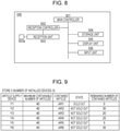
- Fig. 8 illustrates a control system of a management server 500.
- Fig. 9 illustrates an example of a management table displayed on a display unit 505 of the management server 500.
- this article supply system includes one or more article supply devices 100 (six article supply devices in the illustrated example) installed in or near a store, and a communication means (no reference numeral) that can transmit the sold-out signal and the supply signal from each article supply device 100 to the management server 500 via a communication network 400 (the Internet communication network in the illustrated example), the communication means corresponding to the first communication apparatus 200 and the second communication apparatus 300 (see Fig. 4 ).
- a communication network 400 the Internet communication network in the illustrated example
- the article supply system includes one or more article supply devices 100 (six article supply devices in the illustrated example), a communication means (no reference numeral) that can transmit the sold-out signal and the supply signal from each article supply device 100 (the communication means corresponding to the first communication apparatus 200 and the second communication apparatus 300), and the management server 500, which can receive the sold-out signal and the supply signal from the communication means via the communication network 400.
- the communication means includes the first communication apparatus 200 (see Fig. 5 ), which is connected to the output terminals 154a of the respective article supply devices 100 with dedicated cables CA (see Fig. 6 ), and the second communication apparatus 300, which can wirelessly communicate with the first communication apparatus 200 and can communicate with the management server 500 via the Internet communication network 400. That is, each article supply device 100, the first communication apparatus 200, and the second communication apparatus 300 are installed in the store (including at the front of and inside the store), and the maintenance contractor has the management server 500.
- the control system of the first communication apparatus 200 includes, as illustrated in Fig. 5 , a main controller 201 having a microcomputer configuration, a reception controller 202, a transmission controller 203, a transmission unit 204, and an antenna unit 205.
- the reception controller 202 has a plurality of input terminals 202a to 202f (six input terminals in the illustrated example) and has, for example, the function of identifying, for each of the input terminals 202a to 202f, the article supply device 100 from which the sold-out signal and the supply signal input to the input terminal originated, and the function of preventing interference between two or more simultaneously input signals regardless of whether the signals are the sold-out or supply signals.
- the transmission controller 203 has, for example, the function of multiplexing signals from the reception unit controller 202 to perform conversion into a signal appropriate for the communication scheme of the transmission unit 204.
- the transmission unit 204 includes a transmission device that supports a wireless communication standard such as Bluetooth (registered trademark) or Wi-Fi (registered trademark), and can transmit a signal from the transmission controller 203 through the antenna unit 204.
- a wireless communication standard such as Bluetooth (registered trademark) or Wi-Fi (registered trademark)
- power for the control system may be acquired from a commercial power supply using an AC-DC adapter other than from batteries or rechargeable batteries.
- the identification and multiplexing described above will be described in more detail.
- the sold-out signals or the supply signals from two or more of the article supply devices 100 may be simultaneously transmitted to the first communication apparatus 200.
- identification data corresponding to the article supply device 100 is assigned after the sold-out signal and the supply signal are input to the reception controller 202. Since the first communication apparatus 200 is connected to the six article supply devices 100, multiplexing is performed so that, for example, even in a case where the sold-out signal is transmitted from one out of two of the article supply devices 100 and the supply signal is transmitted from the other one of the two article supply devices 100, these signals can be transmitted without problems.
- the control system of the second communication apparatus 300 includes, as illustrated in Fig. 7 , a main controller 301 having a microcomputer configuration, a reception unit 302, an antenna unit 303, a transmission controller 304, and a transmission unit 305.
- the reception unit 302 includes a reception device that supports the same wireless communication standard as the transmission unit 203 of the first communication apparatus 200, and can receive a signal from the first communication apparatus 200 through the antenna unit 303.
- the transmission controller 304 has, for example, the function of multiplexing signals from the reception unit 302 to perform conversion into a signal appropriate for the communication scheme of the transmission unit 305.
- the transmission unit 305 includes a transmission device that supports an Internet communication scheme such as TCP/IP, and has an output terminal 305a, which can be connected to the Internet communication network 400 via a modem or a router (not illustrated).
- power for the control system may be acquired from a commercial power supply using an AC-DC adapter other than from batteries or rechargeable batteries.
- the control system of the management server 500 includes, as illustrated in Fig. 8 , a main controller 501 having a microcomputer configuration, a reception controller 502, a reception unit 503, a storage unit 504, the display unit 505 such as a liquid crystal display, and an input unit 506 such as a keyboard.
- the management server 500 is a general-purpose computer to which a management function described below is added.
- the reception unit 503 includes a reception device that supports an Internet communication scheme such as TCP/IP, and has an input terminal 503a, which can be connected to the Internet communication network 400 via a modem or a router (not illustrated).
- the reception controller 502 has, for example, the function of converting a signal from the reception unit 503 into a signal that can be processed internally.
- the storage unit 504 stores management data in which, for example, the number and the types of article supply devices 100 installed in a store, the maximum containable number of articles, contained articles, the state of each article supply device 100 (the sold-out state and the not-sold-out state), and the remaining number of contained articles are collected on a store-by-store basis.
- the display unit 505 displays a store-specific management table based on the above management data (see Fig. 9 ), and the input unit 506 is used when a numerical value or the like in the management table is changed.
- the six article supply devices 100 are installed so as to be stacked as in Fig. 6 at the front of or inside the store (as a matter of course, the six article supply devices 100 may be installed side by side).
- the first communication apparatus 200 is fixed to the back surface of any one of the article supply devices 100 with screws or the like.
- the output terminals 154a of the respective article supply devices 100 and the input terminals 202a to 202f of the first communication apparatus 200 are connected by the dedicated cables CA.
- the second communication apparatus 300 is installed inside the store, and its output terminal 305a is connected to the Internet communication network 400 via a modem or a router.
- the distance to be set between the first communication apparatus 200 and the second communication apparatus 300 depends on the presence or absence of an obstruction, it is desirable that the distance between the first communication apparatus 200 and the second communication apparatus 300 be less than or equal to 10 m when the wireless communication standard of the apparatuses is Bluetooth (registered trademark) and 30 mm when the wireless communication standard of the apparatuses is Wi-Fi (registered trademark).
- the sold-out signal and the supply signal from each article supply device 100 are transmitted to the management server 500, which the maintenance contractor has, via the first communication apparatus 200, the second notification communication apparatus 300, and the Internet communication network 400 as described above.
- the management server 500 When the management server 500 receives the above sold-out signal and the above supply signal, the management server 500 reads out management data on a store corresponding to the source of the signals from the storage unit 504 and displays the management table illustrated in Fig. 9 on the display unit 504.
- the management table illustrated in Fig. 9 includes the number and the types of article supply devices 100 installed in a store X, the maximum containable number of articles, and contained articles, and furthermore display fields of the states of the respective article supply devices 100 (the sold-out state and the not-sold-out state) and the remaining number of contained articles.
- the management server 500 when the management server 500 receives the sold-out signal regarding the article supply device Y1, the management table corresponding to the store X is displayed on the display unit 505, and also "sold out” is displayed in the state field of the article supply device Y1 in the management table, preferably in an enhanced manner.
- the numerical value in the field of the remaining number of contained articles of the article supply device Y1 is reduced on the basis of reception of the supply signal, and thus the remaining number of contained articles at the stage when the sold-out signal is received is "0" as a general rule.
- the desired article supply device Y1 can be replenished with articles AR1 not long after the time when the article supply device Y1 actually entered the sold-out state.
- the article supply device Y5 having a small remaining number of contained articles the remaining number of contained articles is 5
- the day when the article supply device Y5 will enter the sold-out state can be roughly estimated, and thus preparations for the replenishment of articles AR5 can be made in advance before the article supply device Y5 enters the sold-out state.
- the supply blocking unit 110 illustrated in Fig. 2(A) is rotated and displaced to the position illustrated in Fig. 2(B) , the sold-out signal transmission to the management server 500 is stopped, and the display in the state field of the article supply device Y1 is switched to "not sold out" (the remaining number of contained articles is also switched to 40).
- the completion of replenishment of the desired article supply device Y1 with the articles AR1 can be confirmed.
- the above sold-out signal may be stopped for a moment due to, for example, shock from the outside as described above, and thus it is preferable that the time when the above supply signal is received after the above true selling out is recognized, that is, when the first article AR is supplied after replenishment be recognized as true sold-out elimination (completion of article replenishment).
- the communication network 400 in the above article supply system may be a communication network other than the Internet communication network such as a mobile phone communication network, a wide area network (WAN), or a local-area network (LAN).
- WAN wide area network
- LAN local-area network
- the case where the maintenance contractor has the management server 500 has been described; however, in a case where the article supply device or devices 100 are managed by the store (a case where management of the article supply device or devices 100 is not entrusted to a maintenance contractor), the management server 500 may be installed in, for example, an office of the store.
Landscapes
- General Physics & Mathematics (AREA)
- Physics & Mathematics (AREA)
- Business, Economics & Management (AREA)
- Engineering & Computer Science (AREA)
- Economics (AREA)
- Marketing (AREA)
- Tourism & Hospitality (AREA)
- Human Resources & Organizations (AREA)
- Development Economics (AREA)
- Operations Research (AREA)
- Quality & Reliability (AREA)
- Strategic Management (AREA)
- Entrepreneurship & Innovation (AREA)
- Finance (AREA)
- General Business, Economics & Management (AREA)
- Accounting & Taxation (AREA)
- Theoretical Computer Science (AREA)
- Control Of Vending Devices And Auxiliary Devices For Vending Devices (AREA)
- Vending Machines For Individual Products (AREA)
Abstract
Description
- The present invention relates to an article supply device that can supply an article in accordance with a supply operation and an article supply system using the article supply device.
- In PTL 1, which is described later, a vending machine (hereinafter simply referred to as device) is disclosed that can discharge a capsule item in a box from a drum to an item discharge port in response to a handle being turned after insertion of a coin to rotate the drum. This device has a liquid crystal display means. When the capsule item is out of stock in the box, the apparatus can cause the liquid crystal display means to indicate that the capsule item is sold out.
- The above selling out is generally confirmed by an on-the-road staff member of a maintenance contractor to which management of the device is entrusted or an employee of a store where the device is installed, and thus there may be a time difference between the time when the capsule item actually sold out and the time when the selling out is actually confirmed. This time difference corresponds to the duration of a sold-out state, and thus especially when the sold-out state is of long duration, there are concerns that, for example, prospective consumers would feel inconvenienced and their impression of the store would worsen.
- PTL 1:
Japanese Unexamined Patent Application Publication No. 2006-178612 - A problem to be solved by the present invention is to provide an article supply device and an article supply system that can minimize inconvenience due to selling out. Solution to Problem
- An article supply device according to the present invention includes an article supply means capable of supplying an article in an article container unit in response to a supply operation performed on a supply operation unit, and a sold-out signal transmission means capable of transmitting a sold-out signal when the article is out of stock in the article container unit. An article supply system according to the present invention includes at least one of the above article supply device, and a communication means capable of transmitting, to a management server, the sold-out signal from the article supply device via a communication network. Furthermore, an article supply system according to the present invention includes at least one of the above article supply device, a communication means capable of transmitting the sold-out signal from the article supply device, and a management server capable of receiving the sold-out signal from the communication means via a communication network.
- With an article supply device and an article supply system according to the present invention, inconvenience due to selling out can be minimized.
-
- [
Fig. 1] Fig. 1(A) is a front view of an article supply device, which is an application of the present invention,Fig. 1(B) is a left side view of the article supply device,Fig. 1(C) is a vertical sectional view of the article supply device, andFigs. 1(D) and 1(E) are diagrams for describing articles that can be contained in an article container unit illustrated inFigs. 1(A) to 1(C) . - [
Fig. 2] Figs. 2(A) and 2(B) are diagrams for describing a supply blocking unit illustrated inFig. 1(A) . - [
Fig. 3] Fig. 3 is a diagram for describing a control system of the article supply device illustrated inFigs. 1(A) to 1(C) . - [
Fig. 4] Fig. 4 is a schematic diagram of an article supply system, which is an application of the present invention. - [
Fig. 5] Fig. 5 is a diagram for describing a control system of a first communication apparatus illustrated inFig. 4 . - [
Fig. 6] Fig. 6 is a diagram for describing a connection form of the first communication apparatus illustrated inFig. 4 . - [
Fig. 7] Fig. 7 is a diagram for describing a control system of a second communication apparatus illustrated inFig. 4 . - [
Fig. 8] Fig. 8 is a diagram for describing a control system of a management server illustrated inFig. 4 . - [
Fig. 9] Fig. 9 is a diagram illustrating an example of a management table displayed on a display unit of the management server illustrated inFig. 4 . -
Figs. 1(A) to 1(C) illustrate the configuration of anarticle supply device 100 according to an application of the present invention.Figs. 1(D) and 1(E) illustrate articles AR.Figs. 2(A) and 2(B) illustrate the configuration and operation of asupply blocking unit 110.Fig. 3 illustrates a control system of thearticle supply device 100. - First, the configurations of the articles AR and the configuration of the
article supply device 100 will be described. In a description of thearticle supply device 100, for convenience' sake, the front side ofFig. 1(A) is referred to as front, the depth side ofFig. 1(A) as rear, the left side ofFig. 1(A) as right, the right side ofFig. 1(A) as left, the upper side ofFig. 1(A) as up, and the lower side ofFig. 1(A) as down. Substantially the same applies to the directions inFigs. 1(B), 1(C), 2(A), and 2(B) . A state where there is an article AR in anarticle container unit 102 of thearticle supply device 100 is referred to as a "not-sold-out state", and a state where there is not an article AR in thearticle container unit 102 is referred to as a "sold-out state". - Regarding the articles AR, there are no special limitations as long as the articles AR have spherical external shapes or shapes similar to a sphere, that is, as long as the articles can roll. A specific example may be an article formed by a capsule having a toy inside, the capsule being constituted by two capsule constituent parts that are detachable from and attachable to each other (see
Fig. 1(D) ), an article obtained by covering, with a film or the like, the surface of a toy folded into a somewhat spherical shape (see Fig. 1(F)), or the like. Although depending on the outer shapes of the articles AR, the maximum containable number of articles AR in thearticle container unit 102 is set within a range from about 40 to 120. - The
article supply device 100 includes a devicemain unit 101, thearticle container unit 102, asupply operation unit 103, an article supply means (no reference numeral), anarticle outlet 104, acoin slot 105, acoin return button 106, acoin return slot 107, a sold-out signal transmission means (no reference numeral), and a supply signal transmission means (no reference numeral) (seeFigs. 1(A), 1(B), and 1(C) ). - Note that the
coin slot 105 is a section from which a coin such as a 500 yen coin is inserted, thecoin return button 106 is an item for returning the inserted coin, and thecoin return slot 107 is a section from which a returned coin is taken out. These are publicly known, for example, fromJapanese Unexamined Patent Application Publication No. 2016-053993 - The exterior of the device
main unit 101 has a substantially rectangular parallelepiped shape, and the upper portion of the front surface, the left side surface, and the right side surface of the devicemain unit 101 is open such that acontainer entrance port 101a is provided (seeFigs. 1(A) and 1(B) ). That is, thearticle container unit 102 is arranged such that the front wall and front portions of the left and right side walls are exposed and such that thearticle container unit 102 can be pulled out from the devicemain unit 101. Thearticle container unit 102 can be pulled out through thecontainer entrance port 101a toward the front by unlocking a lock unit that is not illustrated (seeFig. 1(C) ). - The
article container unit 102 includes an open-topped box having a substantially rectangular parallelepiped shape, and at least the front wall and the front portions of the left and right side walls of thearticle container unit 102 are made transparent or semi-transparent (seeFigs. 1(A), 1(B), and 1(C) ). That is, a printed sheet (not illustrated) that is arranged inside the front wall (for example, a sheet presenting a picture or a description of an article AR) can be visually recognized from the outside through the front wall, and the article AR contained in thearticle container unit 102 can be visually recognized from the outside through the front portions of the left and right side walls. - The top surface of a
lower wall 102a of thearticle container unit 102 is flat, and aslope unit 102b for guiding articles AR backward is formed on a front portion of the top surface of thelower wall 102a (seeFig. 1(C) ). Furthermore, a rear portion of the top surface of thelower wall 102a has a hollow section 102a1, which is circular in top view, and the bottom surface of the hollow section 102a1 has an article supply port 102a2, which is circular in top view (seeFigs. 1(C), 2(A), and 2(B) ). - The
supply operation unit 103 has a disc shape with a knob and is arranged on the front surface of the front wall of the devicemain unit 110 so as to be rotatable (seeFigs. 1(A) and 1(B) ). A front end of ashaft 103a is coupled to thesupply operation unit 103, and a rear end of theshaft 103 is supported by the front surface of the rear wall of the devicemain unit 110 so as to be rotatable (seeFig. 1(C) ). Thesupply operation unit 103 is a portion on which a supply operation is performed, and the supply operation is for example a 360-degree rotation of thesupply operation unit 103 when thesupply operation unit 103 is viewed from the front. Agear mechanism 103b including a plurality of gears, which can transfer rotation of theshaft 103 to anarticle supply unit 108, is provided at and above the rear portion of theshaft 103a of the supply operation unit 103 (seeFig. 1(C) ). - The article supply means (no reference numeral) includes the
article supply unit 108, asupply path unit 109, and the supply blocking unit 110 (seeFigs. 1(C), 2(A), and 2(B) ). Thearticle supply unit 108 can supply an article AR in response to an operation based on the supply operation performed in the not-sold-out state. Thesupply path unit 109 guides, to thearticle outlet 104, the article AR supplied from thearticle supply unit 108. Thesupply blocking unit 110 makes thearticle supply unit 108 inoperable in the sold-out state even when the supply operation is performed. - The
article supply unit 108 has an overall disc shape and has a plurality ofsupport holes 108a (five support holes in the drawings) spaced angularly uniformly in top view (seeFigs. 2(A) and 2(B) ). The top view shape of eachsupport hole 108a is a circle slightly larger than the outside shape of the article AR, and the outer side of an inner peripheral surface of eachsupport hole 108a is partially open. Thearticle supply unit 108 is arranged in the hollow section 102a1 of thearticle container unit 102 so as to be rotatable and such that the upper portion of eacharticle support hole 108 protrudes upward from the top surface of thelower wall 102a of the article container unit 102 (seeFig. 1(C) ). - The top surface of the
article supply unit 108 has anagitation unit 108b in the center thereof (seeFig. 1(C) , not illustrated inFig. 2 ). Theagitation unit 108b includes a center protrusion and a plurality of flexible parts (for example, items like extension coil springs) arranged around the center protrusion. - Furthermore, although not illustrated, teeth are provided along the periphery of the bottom surface of the
article supply unit 108, the teeth being similar to face gear teeth. Some of the teeth are positioned in a hole provided in the bottom surface of the hollow section 102a1 of thearticle container unit 102 and engage with the top gear of thegear mechanism 103b of thesupply operation unit 103. That is, thearticle supply unit 108 can rotate by a predetermined angle in response to the performed supply operation. - The
supply path unit 109 has a tubular shape that is curved or bent as a whole and has asupply path 109a extending from a lower end of the article supply port 102a2 present at the bottom surface of the hollow section 102a1 of thearticle container unit 102 to a rear end of the article outlet 104 (seeFig. 1(C) ). In this regard, thesupply path unit 109 does not have to have a tubular shape as long as thesupply path unit 109 can guide, to thearticle outlet 104, the article AR supplied from thearticle supply unit 108. For example, a curved or bent groove provided inside the devicemain unit 101 can be substituted. - The
supply blocking unit 110 is formed of a part that is overall L-shaped or J-shaped, is arranged on the top surface of thelower wall 102a of thearticle container unit 102 so as to be rotatable, and is urged in a clockwise direction, when viewed in top view, by a spring member such as a helical torsion spring or a compression spring, which is not illustrated (seeFigs. 2(A) and 2(B) ). - That is, when the state enters the sold-out state, and an article AR is not held in an upper-left
support hole 108a of thesupply unit 108 inFig. 2(A) , a rear end portion of thesupply blocking unit 110 is rotated and displaced so as to enter thesupport hole 108a, so that thesupply blocking unit 110 can make thearticle supply unit 108 inoperable. - In contrast, when the state is the not-sold-out state, and an article AR is held in the upper-left
support hole 108a of thearticle supply unit 108 inFig. 2(B) , thesupply blocking unit 110 cannot be displaced as above due to the article AR, and thus thesupply blocking unit 110 cannot make thearticle supply unit 108 inoperable. - The sold-out signal transmission means (no reference numeral) is a means that can transmit a sold-out signal when the state enters the sold-out state, and includes a sold-out
detection unit 152, which can detect selling out when thesupply blocking unit 110 is rotated and displaced to a position at which thesupply blocking unit 110 makes thearticle supply unit 108 inoperable (seeFig. 3 ). The sold-outdetection unit 152 includes, for example, at least amagnet unit 111, which is provided at a front end portion of thesupply blocking unit 110, and afirst switch unit 112, which is operated by magnetic force from the magnet unit 111 (seeFigs. 1(C) and 2(B) ). - In the illustrated example, the
magnet unit 111 is provided in thearticle container unit 102, and thefirst switch unit 112 is provided (lower than the article container unit 102) in the devicemain unit 101. Thus, thelower wall 102a of thearticle container unit 102 is provided with a columnar magnetic material unit for transferring magnetic force from themagnet unit 111 to the first switch unit 112 (seeFigs. 1(C), 2(A), and 2(B) ). In this regard, themagnet unit 111 preferably includes a rare earth magnet such as a neodymium magnet or a samarium-cobalt magnet, thefirst switch unit 112 preferably includes a reed switch, and themagnetic material unit 113 preferably includes a ferromagnet such as iron. Note that in a case where thefirst switch unit 112 can be provided on thearticle container unit 102 side, themagnetic material unit 113 is not always necessary. - That is, when the state enters the sold-out state, and an article AR is not held in the upper-left
support hole 108a of thearticle supply unit 108 inFig. 2(A) , the rear end portion of thesupply blocking unit 110 is rotated and displaced so as to enter the upper-leftsupport hole 108a, so that themagnet unit 111 is displaced onto themagnetic material unit 113 by the rotational displacement. Thus, magnetic force from themagnet unit 111 is transferred via themagnetic material unit 113 to thefirst switch unit 112, and thefirst switch unit 112 can be operated. - In contrast, when the state is the not-sold-out state, and an article AR is held in the upper-left
support hole 108a of thearticle supply unit 108 inFig. 2(B) , thesupply blocking unit 110 cannot be displaced as above due to the article AR, and themagnet unit 111 is positioned away from themagnetic material unit 113. Thus, thefirst switch unit 112 cannot be operated. - The supply signal transmission means (no reference numeral) is a means that can transmit a supply signal in response to the supply operation performed when there is an article AR in the
article container unit 102, and includes asupply detection unit 153, which can detect supply when the supply operation is performed (seeFig. 3 ). Thesupply detection unit 153 includes, for example, aswitch operation unit 114, which can be displaced on the basis of performance of the supply operation, and asecond switch unit 115, which operates on the basis of the displacement of the switch operation unit 114 (seeFig. 1(C) ). - The
switch operation unit 114 preferably includes a rotation displacement part such as an eccentric cam provided at theshaft unit 103a of thesupply operation unit 103. Thesecond switch unit 115 preferably includes a press switch such as a microswitch, the press switch being capable of operating when the rotation displacement part is displaced partway such as when thesupply operation unit 103 is rotated by 180 degrees to 270 degrees (seeFig. 1(C) ). - That is, in a case where the supply operation is performed on the
supply operation unit 103 in the not-sold-out state, and theshaft unit 103a and theswitch operation unit 114 rotate by 360 degrees, thesecond switch unit 115 can be operated one time when theswitch operation unit 114 is rotated and displaced partway. - Next, the control system of the
article supply device 100 described above will be described. This control system includes, as illustrated inFig. 3 , amain controller 151 having a microcomputer configuration, the sold-outdetection unit 152, thesupply detection unit 153, and atransmission unit 154. - The sold-out
detection unit 152 includes the abovefirst switch unit 112, and thesupply detection unit 153 includes the abovesecond switch unit 115. Thetransmission unit 154 has a dual-purpose output terminal 154a, which can transmit a sold-out signal (preferably, a binary signal) detected by the sold-outdetection unit 152 and a supply signal (preferably, a binary signal) detected by thesupply detection unit 153. Theoutput terminal 154a is provided at the back surface of the devicemain unit 101. Power for the control system may be acquired from a commercial power supply using an alternating-current-to-direct-current (AC-DC) adapter other than from batteries or rechargeable batteries. - Next, the operation of the
article supply device 100 described above will be described. - When a certain coin is inserted into the
coin slot 105 and the supply operation is performed on thesupply operation unit 103 in the not-sold-out state (seeFig. 1(C) ), thearticle supply unit 108 rotates by a predetermined angle, the article AR held in thesupport hole 108a falls into thesupply path unit 109 through the article supply port 102a2 (seeFig. 2(B) ), and the article AR is guided to thearticle outlet 104 through thesupply path 109a. - In contrast, when the state enters the sold-out state, the rear end portion of the
supply blocking unit 110 enters thesupport hole 108a, and thearticle supply unit 108 is made inoperable (seeFig. 2(A) ) as described above. Thus, the supply operation cannot be performed on thesupply operation unit 103. - When the supply operation (a 360 degree rotation) is performed on the
supply operation unit 103 in the not-sold-out state, the supply signal is transmitted to theoutput terminal 154a of thetransmission unit 154, the supply signal being based on a detection signal from thesecond switch unit 115 included in thesupply detection unit 153. - Furthermore, when the state enters the sold-out state, the sold-out signal is transmitted to the
output terminal 154a of thetransmission unit 154, the sold-out signal being based on a detection signal from thefirst switch unit 112 included in the sold-outdetection unit 152. - In this regard, from one
article supply device 100, the sold-out signal is normally transmitted after the supply signal is transmitted. In other words, the supply signal and the sold-out signal are not simultaneously transmitted from onearticle supply device 100, and thus signal control for transmitting these signals is unnecessary. - Thus, even when any one of a plurality of
article supply devices 100 enters the sold-out state, the sold-out signal is immediately transmitted from thearticle supply device 100. Thus, the selling out of the article AR can be confirmed without a time lag by using the sold-out signal. The supply signal is transmitted every time the article AR is supplied in the not-sold-out state, and thus the remaining number of articles contained in eacharticle supply device 100 can be checked using the supply signal. - Note that the above
article supply device 100 may display a sold-out indication in order to allow consumers to visually confirm that thearticle supply device 100 is in the sold-out state. For this sold-out indication, for example, it is preferable that a mechanism as described inJapanese Unexamined Patent Application Publication No. 2016-053993 article container unit 102, and the sold-out display unit can be recognized from the outside by being rotated using a rotational displacement to protrude downward from a hole provided in a front end of thelower wall 102a of thearticle container unit 102, the rotational displacement being caused when the rear end portion of thesupply blocking unit 110 enters the upper-leftsupport hole 108a of thearticle supply unit 108 inFig. 2(A) . - In a case where only the sold-out signal is transmitted, the supply signal transmission means (no reference numeral) may be eliminated from the above
article supply device 100, and only the sold-out signal transmission means (no reference numeral) may be provided. Furthermore, the dual-purpose output terminal 154a provided at thetransmission unit 154 may be divided into an output terminal for the sold-out signal detected by the sold-outdetection unit 152 and an output terminal for the supply signal detected by thesupply detection unit 153. -
Fig. 4 illustrates a schematic configuration of an article supply system (no reference numeral) according to an application of the present invention.Fig. 5 illustrates a control system of afirst communication apparatus 200.Fig. 6 illustrates a connection form of thefirst communication apparatus 200.Fig. 7 illustrates a control system of asecond communication apparatus 300.Fig. 8 illustrates a control system of amanagement server 500.Fig. 9 illustrates an example of a management table displayed on adisplay unit 505 of themanagement server 500. - First, the configuration of the article supply system (no reference numeral) will be described. In a case where the management of
article supply devices 100 is entrusted to a maintenance contractor, this article supply system (no reference numeral) includes one or more article supply devices 100 (six article supply devices in the illustrated example) installed in or near a store, and a communication means (no reference numeral) that can transmit the sold-out signal and the supply signal from eacharticle supply device 100 to themanagement server 500 via a communication network 400 (the Internet communication network in the illustrated example), the communication means corresponding to thefirst communication apparatus 200 and the second communication apparatus 300 (seeFig. 4 ). - In other words, the article supply system (no reference numeral) includes one or more article supply devices 100 (six article supply devices in the illustrated example), a communication means (no reference numeral) that can transmit the sold-out signal and the supply signal from each article supply device 100 (the communication means corresponding to the
first communication apparatus 200 and the second communication apparatus 300), and themanagement server 500, which can receive the sold-out signal and the supply signal from the communication means via thecommunication network 400. - The communication means (no reference numeral) includes the first communication apparatus 200 (see
Fig. 5 ), which is connected to theoutput terminals 154a of the respectivearticle supply devices 100 with dedicated cables CA (seeFig. 6 ), and thesecond communication apparatus 300, which can wirelessly communicate with thefirst communication apparatus 200 and can communicate with themanagement server 500 via theInternet communication network 400. That is, eacharticle supply device 100, thefirst communication apparatus 200, and thesecond communication apparatus 300 are installed in the store (including at the front of and inside the store), and the maintenance contractor has themanagement server 500. - The control system of the
first communication apparatus 200 includes, as illustrated inFig. 5 , amain controller 201 having a microcomputer configuration, areception controller 202, atransmission controller 203, atransmission unit 204, and anantenna unit 205. - The
reception controller 202 has a plurality ofinput terminals 202a to 202f (six input terminals in the illustrated example) and has, for example, the function of identifying, for each of theinput terminals 202a to 202f, thearticle supply device 100 from which the sold-out signal and the supply signal input to the input terminal originated, and the function of preventing interference between two or more simultaneously input signals regardless of whether the signals are the sold-out or supply signals. Thetransmission controller 203 has, for example, the function of multiplexing signals from thereception unit controller 202 to perform conversion into a signal appropriate for the communication scheme of thetransmission unit 204. Thetransmission unit 204 includes a transmission device that supports a wireless communication standard such as Bluetooth (registered trademark) or Wi-Fi (registered trademark), and can transmit a signal from thetransmission controller 203 through theantenna unit 204. In this regard, power for the control system may be acquired from a commercial power supply using an AC-DC adapter other than from batteries or rechargeable batteries. - The identification and multiplexing described above will be described in more detail. The sold-out signals or the supply signals from two or more of the
article supply devices 100 may be simultaneously transmitted to thefirst communication apparatus 200. Thus, to the sold-out signal and the supply signal from eacharticle supply device 100, identification data corresponding to thearticle supply device 100 is assigned after the sold-out signal and the supply signal are input to thereception controller 202. Since thefirst communication apparatus 200 is connected to the sixarticle supply devices 100, multiplexing is performed so that, for example, even in a case where the sold-out signal is transmitted from one out of two of thearticle supply devices 100 and the supply signal is transmitted from the other one of the twoarticle supply devices 100, these signals can be transmitted without problems. - The control system of the
second communication apparatus 300 includes, as illustrated inFig. 7 , amain controller 301 having a microcomputer configuration, areception unit 302, anantenna unit 303, atransmission controller 304, and atransmission unit 305. - The
reception unit 302 includes a reception device that supports the same wireless communication standard as thetransmission unit 203 of thefirst communication apparatus 200, and can receive a signal from thefirst communication apparatus 200 through theantenna unit 303. Thetransmission controller 304 has, for example, the function of multiplexing signals from thereception unit 302 to perform conversion into a signal appropriate for the communication scheme of thetransmission unit 305. Thetransmission unit 305 includes a transmission device that supports an Internet communication scheme such as TCP/IP, and has anoutput terminal 305a, which can be connected to theInternet communication network 400 via a modem or a router (not illustrated). In this regard, power for the control system may be acquired from a commercial power supply using an AC-DC adapter other than from batteries or rechargeable batteries. - The control system of the
management server 500 includes, as illustrated inFig. 8 , amain controller 501 having a microcomputer configuration, areception controller 502, areception unit 503, astorage unit 504, thedisplay unit 505 such as a liquid crystal display, and aninput unit 506 such as a keyboard. In this regard, themanagement server 500 is a general-purpose computer to which a management function described below is added. - The
reception unit 503 includes a reception device that supports an Internet communication scheme such as TCP/IP, and has aninput terminal 503a, which can be connected to theInternet communication network 400 via a modem or a router (not illustrated). Thereception controller 502 has, for example, the function of converting a signal from thereception unit 503 into a signal that can be processed internally. Thestorage unit 504 stores management data in which, for example, the number and the types ofarticle supply devices 100 installed in a store, the maximum containable number of articles, contained articles, the state of each article supply device 100 (the sold-out state and the not-sold-out state), and the remaining number of contained articles are collected on a store-by-store basis. Thedisplay unit 505 displays a store-specific management table based on the above management data (seeFig. 9 ), and theinput unit 506 is used when a numerical value or the like in the management table is changed. - Next, an example of a method for installing the six
article supply devices 100, thefirst communication apparatus 200, and thesecond communication apparatus 300 of the above article supply system (no reference numeral) will be described. - First, the six
article supply devices 100 are installed so as to be stacked as inFig. 6 at the front of or inside the store (as a matter of course, the sixarticle supply devices 100 may be installed side by side). Thefirst communication apparatus 200 is fixed to the back surface of any one of thearticle supply devices 100 with screws or the like. Theoutput terminals 154a of the respectivearticle supply devices 100 and theinput terminals 202a to 202f of thefirst communication apparatus 200 are connected by the dedicated cables CA. - The
second communication apparatus 300 is installed inside the store, and itsoutput terminal 305a is connected to theInternet communication network 400 via a modem or a router. Although the distance to be set between thefirst communication apparatus 200 and thesecond communication apparatus 300 depends on the presence or absence of an obstruction, it is desirable that the distance between thefirst communication apparatus 200 and thesecond communication apparatus 300 be less than or equal to 10 m when the wireless communication standard of the apparatuses is Bluetooth (registered trademark) and 30 mm when the wireless communication standard of the apparatuses is Wi-Fi (registered trademark). - Next, the operation of the above article supply system (no reference numeral) will be described, which includes the six
article supply devices 100. - Description will be made starting from the state in which the above installation is completed and in which articles AR, the number of which is a maximum (for example, 40), are contained in the
article container unit 102 of eacharticle supply device 100. The numbers of articles AR in thearticle container units 102 of the individualarticle supply devices 100 gradually decrease due to the above supply operation performed by consumers. In this regard, the rates of decrease of the articles AR in thearticle container units 102 of the individualarticle supply devices 100 vary depending on demand, and thus the ways in which the articles AR decrease vary between thearticle supply devices 100. - The sold-out signal and the supply signal from each
article supply device 100 are transmitted to themanagement server 500, which the maintenance contractor has, via thefirst communication apparatus 200, the secondnotification communication apparatus 300, and theInternet communication network 400 as described above. - When the
management server 500 receives the above sold-out signal and the above supply signal, themanagement server 500 reads out management data on a store corresponding to the source of the signals from thestorage unit 504 and displays the management table illustrated inFig. 9 on thedisplay unit 504. In this regard, the management table illustrated inFig. 9 includes the number and the types ofarticle supply devices 100 installed in a store X, the maximum containable number of articles, and contained articles, and furthermore display fields of the states of the respective article supply devices 100 (the sold-out state and the not-sold-out state) and the remaining number of contained articles. - For example, among six article supply devices Y1 to Y6 installed in the store X, when the
management server 500 receives the sold-out signal regarding the article supply device Y1, the management table corresponding to the store X is displayed on thedisplay unit 505, and also "sold out" is displayed in the state field of the article supply device Y1 in the management table, preferably in an enhanced manner. In this regard, the numerical value in the field of the remaining number of contained articles of the article supply device Y1 is reduced on the basis of reception of the supply signal, and thus the remaining number of contained articles at the stage when the sold-out signal is received is "0" as a general rule. That is, as a result of a change to "sold out" in the state field in the management table displayed on thedisplay unit 505, it can be visually confirmed that the article supply device Y1 among the six article supply devices Y1 to Y6 installed in the store X is in the sold-out state and that the sold-out article AR is AR1. - Thus, in a case where an on-the-road staff member of the maintenance contractor replenishes the article supply device Y1 of the store X with articles AR1 on the basis of the display described above, the desired article supply device Y1 can be replenished with articles AR1 not long after the time when the article supply device Y1 actually entered the sold-out state. Moreover, regarding the article supply device Y5 having a small remaining number of contained articles (the remaining number of contained articles is 5), the day when the article supply device Y5 will enter the sold-out state can be roughly estimated, and thus preparations for the replenishment of articles AR5 can be made in advance before the article supply device Y5 enters the sold-out state.
- Moreover, when the article supply device Y1 in the sold-out state is replenished with articles AR1, the
supply blocking unit 110 illustrated inFig. 2(A) is rotated and displaced to the position illustrated inFig. 2(B) , the sold-out signal transmission to themanagement server 500 is stopped, and the display in the state field of the article supply device Y1 is switched to "not sold out" (the remaining number of contained articles is also switched to 40). As a result of this switching in the display, the completion of replenishment of the desired article supply device Y1 with the articles AR1 can be confirmed. - There is a concern that the above sold-out signal would be momentarily generated when the article AR held in the
support hole 108a lifts up due to, for example, thearticle supply device 100 itself receiving shock from the outside in the state illustrated inFig. 2(B) and thesupply blocking unit 110 is rotated and displaced. There is another concern that the above sold-out signal would be momentarily stopped when thesupply blocking unit 110 is rotated and displaced due to inertia even in the state illustrated inFig. 2(A) . Thus, regarding the above sold-out signal, when the above sold-out signal continues for a predetermined time period or longer, specifically three seconds or longer, it is preferable that themanagement server 500 recognizes this as true selling out. - The above sold-out signal may be stopped for a moment due to, for example, shock from the outside as described above, and thus it is preferable that the time when the above supply signal is received after the above true selling out is recognized, that is, when the first article AR is supplied after replenishment be recognized as true sold-out elimination (completion of article replenishment).
- Note that the
communication network 400 in the above article supply system may be a communication network other than the Internet communication network such as a mobile phone communication network, a wide area network (WAN), or a local-area network (LAN). The case where the maintenance contractor has themanagement server 500 has been described; however, in a case where the article supply device ordevices 100 are managed by the store (a case where management of the article supply device ordevices 100 is not entrusted to a maintenance contractor), themanagement server 500 may be installed in, for example, an office of the store. -
- 100
- article supply device
- 101
- device main unit
- 102
- article container unit
- 103
- supply operation unit
- 108
- article supply unit
- 110
- supply blocking unit
- 111
- magnet unit
- 112
- first switch unit
- 113
- magnetic material unit
- 114
- switch operation unit
- 115
- second switch unit
- 152
- sold-out detection unit
- 153
- supply detection unit
- 154
- transmission unit
- 154a
- output terminal
- 200
- first communication apparatus
- 202a to 202f
- input terminal
- 300
- second communication apparatus
- 305a
- output terminal
- 400
- communication network
- 500
- management server
- 505
- display unit
Claims (24)
- An article supply device including an article supply means capable of supplying an article in an article container unit in response to a supply operation performed on a supply operation unit,
the article supply device comprising:
a sold-out signal transmission means capable of transmitting a sold-out signal when the article is out of stock in the article container unit. - The article supply device according to Claim 1, further comprising:
a supply signal transmission means capable of transmitting a supply signal in response to the supply operation performed when the article is in stock in the article container unit. - The article supply device according to Claim 1 or 2,
wherein the article supply means includes at least an article supply unit capable of supplying the article in response to an operation based on the supply operation performed when the article is in stock in the article container unit, and a supply blocking unit that makes the article supply unit inoperable even in a case where the supply operation is performed when the article is out of stock in the article container unit. - The article supply device according to Claim 3,
wherein the sold-out signal transmission means includes a sold-out detection unit capable of detecting selling out when the supply blocking unit is displaced to a position where the supply blocking unit makes the article supply unit inoperable. - The article supply device according to Claim 4,
wherein the sold-out detection unit includes at least a magnet unit provided at the supply blocking unit, and a first switch unit that is operated by magnetic force from the magnet unit. - The article supply device according to Claim 5,
wherein the sold-out detection unit is configured to transfer magnetic force from the magnet unit to the first switch unit through a magnetic material unit. - The article supply device according to Claim 5 or 6,
wherein the first switch unit includes a reed switch. - The article supply device according to any one of Claims 4 to 7,
wherein the sold-out signal transmission means further includes an output terminal capable of transmitting the sold-out signal detected by the sold-out detection unit. - The article supply device according to any one of Claims 3 to 8,
wherein the supply signal transmission means includes a supply detection unit capable of detecting supply when the supply operation is performed. - The article supply device according to Claim 9,
wherein the supply detection unit includes a switch operation unit capable of being displaced based on the performed supply operation, and a second switch unit that operates based on a displacement of the switch operation unit. - The article supply device according to Claim 10,
wherein the second switch unit includes a press switch capable of operating when the switch operation unit is displaced partway. - The article supply device according to Claim 10 or 11,
wherein the displacement of the switch operation unit is a rotational displacement. - The article supply device according to any one of Claims 9 to 12,
wherein the supply signal transmission means further includes an output terminal capable of transmitting the supply signal detected by the supply detection unit. - The article supply device according to Claim 13,
wherein the output terminal for the supply signal also serves as the output terminal for the sold-out signal according to Claim 8. - An article supply system comprising:at least one of the article supply device according to Claim 1; anda communication means capable of transmitting, to a management server, the sold-out signal from the article supply device via a communication network.
- An article supply system comprising:at least one of the article supply device according to Claim 2; anda communication means capable of transmitting, to a management server, the sold-out signal and the supply signal from the article supply device via a communication network.
- The article supply system according to Claim 15 or 16,
wherein the communication means includes a first communication apparatus connected to an output terminal of the article supply device, and a second communication apparatus that enables wireless communication with the first communication apparatus and that is capable of communicating with the management server via the communication network. - The article supply system according to Claim 17,
wherein the first communication apparatus has a plurality of input terminals connectable to the output terminals of a plurality of the article supply devices in a wired manner. - An article supply system comprising:at least one of the article supply device according to Claim 1;a communication means capable of transmitting the sold-out signal from the article supply device; anda management server capable of receiving the sold-out signal from the communication means via a communication network.
- An article supply system comprising:at least one of the article supply device according to Claim 2;a communication means capable of transmitting the sold-out signal and the supply signal from the article supply device; anda management server capable of receiving the sold-out signal and the supply signal from the communication means via a communication network.
- The article supply system according to Claim 20 or 21,
wherein the communication means includes a first communication apparatus connected to an output terminal of the article supply device, and a second communication apparatus that enables wireless communication with the first communication apparatus and that is capable of communicating with the management server via the communication network. - The article supply system according to Claim 21,
wherein the first communication apparatus has a plurality of input terminals connectable to the output terminals of a plurality of the article supply devices in a wired manner. - The article supply system according to any one of Claims 19 to 22,
wherein the management server is configured to recognize selling out when the sold-out signal from the communication means continues for a predetermined time period or longer. - The article supply system according to Claim 23,
wherein the management server is configured to recognize sold-out elimination when the supply signal according to Claim 21 is received after the selling out is recognized.
Applications Claiming Priority (2)
| Application Number | Priority Date | Filing Date | Title |
|---|---|---|---|
| JP2019130711A JP6821750B1 (en) | 2019-07-12 | 2019-07-12 | Goods supply device and goods supply system |
| PCT/JP2020/024726 WO2021010111A1 (en) | 2019-07-12 | 2020-06-24 | Article supply device and article supply system |
Publications (2)
| Publication Number | Publication Date |
|---|---|
| EP3961590A1 true EP3961590A1 (en) | 2022-03-02 |
| EP3961590A4 EP3961590A4 (en) | 2022-12-28 |
Family
ID=74200245
Family Applications (1)
| Application Number | Title | Priority Date | Filing Date |
|---|---|---|---|
| EP20839565.7A Pending EP3961590A4 (en) | 2019-07-12 | 2020-06-24 | ARTICLE FEEDING DEVICE AND ARTICLE FEEDING SYSTEM |
Country Status (5)
| Country | Link |
|---|---|
| US (1) | US12596989B2 (en) |
| EP (1) | EP3961590A4 (en) |
| JP (1) | JP6821750B1 (en) |
| CN (1) | CN114026619A (en) |
| WO (1) | WO2021010111A1 (en) |
Families Citing this family (2)
| Publication number | Priority date | Publication date | Assignee | Title |
|---|---|---|---|---|
| JP7706211B2 (en) * | 2022-12-22 | 2025-07-11 | 株式会社バンダイ | Goods supply device |
| JP7598918B2 (en) * | 2022-12-23 | 2024-12-12 | 株式会社バンダイ | Item supply device |
Family Cites Families (21)
| Publication number | Priority date | Publication date | Assignee | Title |
|---|---|---|---|---|
| US3264478A (en) * | 1963-04-18 | 1966-08-02 | Richard J Moldovan | Photoconductive time delay device |
| US4576272A (en) * | 1984-06-21 | 1986-03-18 | The Coca-Cola Company | Counter-top or wall-mounted vending machine |
| JPH0954869A (en) * | 1995-08-16 | 1997-02-25 | Fuji Electric Co Ltd | Spiral product rack product sold-out detection device |
| JPH1027278A (en) * | 1996-07-11 | 1998-01-27 | Fuji Electric Co Ltd | Vending machine sold-out detection sensor |
| US6050385A (en) * | 1997-04-15 | 2000-04-18 | Nova Resolution Industries, Inc. | Combination coin mechanism and coin counter, and coin counter individually, for bulk vending machines |
| JP4031641B2 (en) | 2001-12-14 | 2008-01-09 | 株式会社エポック社 | Product take-out device |
| JP4136456B2 (en) * | 2002-05-24 | 2008-08-20 | 富士電機リテイルシステムズ株式会社 | Vending machine inventory management system |
| US7182219B2 (en) * | 2003-10-10 | 2007-02-27 | Kil Jae Chang | Vending machine for dispensing items in small packages |
| JP4814515B2 (en) | 2004-12-21 | 2011-11-16 | 株式会社タカラトミーアーツ | Product management system for product discharge equipment |
| JP4528609B2 (en) | 2004-12-21 | 2010-08-18 | 株式会社タカラトミーアーツ | vending machine |
| JP4814516B2 (en) * | 2004-12-21 | 2011-11-16 | 株式会社タカラトミーアーツ | vending machine |
| JP4536616B2 (en) * | 2005-07-26 | 2010-09-01 | 株式会社タカラトミーアーツ | vending machine |
| TR201815291T4 (en) * | 2005-12-07 | 2018-11-21 | Essity Hygiene & Health Ab | A welding package for use in a device for dispensing sheet material and an apparatus for dispensing sheet material. |
| EP2596191B1 (en) | 2010-07-23 | 2019-05-22 | Kaba Gallenschütz GmbH | Damping unit for discontinuously damping a rotational motion |
| US8651321B2 (en) * | 2011-05-23 | 2014-02-18 | Sweet N Fun, Ltd. | Gumball machine with lights and sound |
| US20140143077A1 (en) * | 2012-11-20 | 2014-05-22 | Rajesh Shah | Automated Print and Digital Media and Communications Vending Kiosk |
| JP6515552B2 (en) | 2015-01-28 | 2019-05-22 | 富士電機株式会社 | Product storage device |
| JP6095755B2 (en) | 2015-12-11 | 2017-03-15 | 株式会社バンダイ | Manual product sales equipment |
| CN108961549A (en) | 2018-09-07 | 2018-12-07 | 虫极科技(北京)有限公司 | A kind of paper handkerchief offer device |
| JP6584615B2 (en) * | 2018-09-26 | 2019-10-02 | 株式会社バンダイ | Manual product sales equipment |
| JP6835921B2 (en) * | 2019-09-02 | 2021-02-24 | 株式会社バンダイ | Manual product sales device |
-
2019
- 2019-07-12 JP JP2019130711A patent/JP6821750B1/en active Active
-
2020
- 2020-06-24 US US17/617,394 patent/US12596989B2/en active Active
- 2020-06-24 EP EP20839565.7A patent/EP3961590A4/en active Pending
- 2020-06-24 WO PCT/JP2020/024726 patent/WO2021010111A1/en not_active Ceased
- 2020-06-24 CN CN202080044207.2A patent/CN114026619A/en active Pending
Also Published As
| Publication number | Publication date |
|---|---|
| EP3961590A4 (en) | 2022-12-28 |
| JP6821750B1 (en) | 2021-01-27 |
| WO2021010111A1 (en) | 2021-01-21 |
| US20220237553A1 (en) | 2022-07-28 |
| US12596989B2 (en) | 2026-04-07 |
| CN114026619A (en) | 2022-02-08 |
| JP2021015524A (en) | 2021-02-12 |
Similar Documents
| Publication | Publication Date | Title |
|---|---|---|
| ES2328005T3 (en) | MONEY HANDLING MECHANISMS WITH PERIPHERAL PORT. | |
| EP3961590A1 (en) | Article supply device and article supply system | |
| CA2232908C (en) | Electronic bulk vending machine system | |
| US5222624A (en) | Ticket dispenser machine and method | |
| US9142079B2 (en) | Coin and bill dispensing safe | |
| JP7396627B2 (en) | gaming machine | |
| JPWO2005024737A1 (en) | Merchandise sales management system and merchandise sales management method | |
| WO2008051567A1 (en) | Wireless, remote or mobile shelf pricing with elongate electronic displays and simplified price changes | |
| CN108577642A (en) | A kind of intelligence apparatus for dispensing tissue | |
| CN120823666A (en) | Item providing device, item providing system and settlement system | |
| US20200082660A1 (en) | Item dispensing device | |
| WO2005022472A1 (en) | Product sail management system and product sail management method therefor | |
| JP4814515B2 (en) | Product management system for product discharge equipment | |
| JP7232272B2 (en) | Article supply device and article supply system | |
| KR20090109451A (en) | Customer Calling Device | |
| US20070170249A1 (en) | Vending machine with dispensing units controlled directly without controller board | |
| KR101429400B1 (en) | Probabilistic vending machine, and driving apparatus and method thereof | |
| SI23467A2 (en) | Mobile gaming device | |
| KR20050044048A (en) | Hotel automation system | |
| KR200368741Y1 (en) | Self service stand system for guest room | |
| RU64801U1 (en) | VENDING MACHINE | |
| KR20150079502A (en) | Vending machine | |
| EP3955197A1 (en) | Payment module for product vending machines | |
| JP2025159433A (en) | Capsule product vending machine, capsule product sales management system, and capsule product dispensing detection method | |
| JP4723924B2 (en) | Amusement stand |
Legal Events
| Date | Code | Title | Description |
|---|---|---|---|
| STAA | Information on the status of an ep patent application or granted ep patent |
Free format text: STATUS: THE INTERNATIONAL PUBLICATION HAS BEEN MADE |
|
| PUAI | Public reference made under article 153(3) epc to a published international application that has entered the european phase |
Free format text: ORIGINAL CODE: 0009012 |
|
| STAA | Information on the status of an ep patent application or granted ep patent |
Free format text: STATUS: REQUEST FOR EXAMINATION WAS MADE |
|
| 17P | Request for examination filed |
Effective date: 20211125 |
|
| AK | Designated contracting states |
Kind code of ref document: A1 Designated state(s): AL AT BE BG CH CY CZ DE DK EE ES FI FR GB GR HR HU IE IS IT LI LT LU LV MC MK MT NL NO PL PT RO RS SE SI SK SM TR |
|
| DAV | Request for validation of the european patent (deleted) | ||
| DAX | Request for extension of the european patent (deleted) | ||
| A4 | Supplementary search report drawn up and despatched |
Effective date: 20221130 |
|
| RIC1 | Information provided on ipc code assigned before grant |
Ipc: G07F 9/02 20060101ALI20221124BHEP Ipc: G07F 11/54 20060101AFI20221124BHEP |
|
| STAA | Information on the status of an ep patent application or granted ep patent |
Free format text: STATUS: EXAMINATION IS IN PROGRESS |
|
| 17Q | First examination report despatched |
Effective date: 20250728 |