EP3961583A2 - Verfahren zur erkennung von hindernissen, elektronische vorrichtung, strassenseitige vorrichtung und cloud-steuerungsplattform - Google Patents
Verfahren zur erkennung von hindernissen, elektronische vorrichtung, strassenseitige vorrichtung und cloud-steuerungsplattform Download PDFInfo
- Publication number
- EP3961583A2 EP3961583A2 EP21217337.1A EP21217337A EP3961583A2 EP 3961583 A2 EP3961583 A2 EP 3961583A2 EP 21217337 A EP21217337 A EP 21217337A EP 3961583 A2 EP3961583 A2 EP 3961583A2
- Authority
- EP
- European Patent Office
- Prior art keywords
- reference points
- obstacle
- coordinates
- determining
- template
- Prior art date
- Legal status (The legal status is an assumption and is not a legal conclusion. Google has not performed a legal analysis and makes no representation as to the accuracy of the status listed.)
- Granted
Links
Images



Classifications
-
- G—PHYSICS
- G06—COMPUTING OR CALCULATING; COUNTING
- G06V—IMAGE OR VIDEO RECOGNITION OR UNDERSTANDING
- G06V20/00—Scenes; Scene-specific elements
- G06V20/50—Context or environment of the image
- G06V20/52—Surveillance or monitoring of activities, e.g. for recognising suspicious objects
- G06V20/54—Surveillance or monitoring of activities, e.g. for recognising suspicious objects of traffic, e.g. cars on the road, trains or boats
-
- G—PHYSICS
- G06—COMPUTING OR CALCULATING; COUNTING
- G06V—IMAGE OR VIDEO RECOGNITION OR UNDERSTANDING
- G06V20/00—Scenes; Scene-specific elements
- G06V20/50—Context or environment of the image
- G06V20/56—Context or environment of the image exterior to a vehicle by using sensors mounted on the vehicle
- G06V20/58—Recognition of moving objects or obstacles, e.g. vehicles or pedestrians; Recognition of traffic objects, e.g. traffic signs, traffic lights or roads
-
- G—PHYSICS
- G06—COMPUTING OR CALCULATING; COUNTING
- G06F—ELECTRIC DIGITAL DATA PROCESSING
- G06F18/00—Pattern recognition
- G06F18/20—Analysing
- G06F18/22—Matching criteria, e.g. proximity measures
-
- G—PHYSICS
- G06—COMPUTING OR CALCULATING; COUNTING
- G06T—IMAGE DATA PROCESSING OR GENERATION, IN GENERAL
- G06T7/00—Image analysis
- G06T7/20—Analysis of motion
- G06T7/269—Analysis of motion using gradient-based methods
-
- G—PHYSICS
- G06—COMPUTING OR CALCULATING; COUNTING
- G06T—IMAGE DATA PROCESSING OR GENERATION, IN GENERAL
- G06T7/00—Image analysis
- G06T7/70—Determining position or orientation of objects or cameras
-
- G—PHYSICS
- G06—COMPUTING OR CALCULATING; COUNTING
- G06V—IMAGE OR VIDEO RECOGNITION OR UNDERSTANDING
- G06V10/00—Arrangements for image or video recognition or understanding
- G06V10/70—Arrangements for image or video recognition or understanding using pattern recognition or machine learning
- G06V10/74—Image or video pattern matching; Proximity measures in feature spaces
- G06V10/75—Organisation of the matching processes, e.g. simultaneous or sequential comparisons of image or video features; Coarse-fine approaches, e.g. multi-scale approaches; using context analysis; Selection of dictionaries
- G06V10/751—Comparing pixel values or logical combinations thereof, or feature values having positional relevance, e.g. template matching
-
- G—PHYSICS
- G06—COMPUTING OR CALCULATING; COUNTING
- G06V—IMAGE OR VIDEO RECOGNITION OR UNDERSTANDING
- G06V10/00—Arrangements for image or video recognition or understanding
- G06V10/70—Arrangements for image or video recognition or understanding using pattern recognition or machine learning
- G06V10/74—Image or video pattern matching; Proximity measures in feature spaces
- G06V10/761—Proximity, similarity or dissimilarity measures
-
- G—PHYSICS
- G06—COMPUTING OR CALCULATING; COUNTING
- G06V—IMAGE OR VIDEO RECOGNITION OR UNDERSTANDING
- G06V30/00—Character recognition; Recognising digital ink; Document-oriented image-based pattern recognition
- G06V30/10—Character recognition
- G06V30/19—Recognition using electronic means
- G06V30/19007—Matching; Proximity measures
-
- G—PHYSICS
- G06—COMPUTING OR CALCULATING; COUNTING
- G06N—COMPUTING ARRANGEMENTS BASED ON SPECIFIC COMPUTATIONAL MODELS
- G06N20/00—Machine learning
-
- G—PHYSICS
- G06—COMPUTING OR CALCULATING; COUNTING
- G06V—IMAGE OR VIDEO RECOGNITION OR UNDERSTANDING
- G06V2201/00—Indexing scheme relating to image or video recognition or understanding
- G06V2201/07—Target detection
-
- G—PHYSICS
- G06—COMPUTING OR CALCULATING; COUNTING
- G06V—IMAGE OR VIDEO RECOGNITION OR UNDERSTANDING
- G06V2201/00—Indexing scheme relating to image or video recognition or understanding
- G06V2201/08—Detecting or categorising vehicles
Definitions
- the present disclosure relates to the field of automatic drive and intelligent traffic, and specifically relates to a method and apparatus for detecting an obstacle, an electronic device, a roadside device, a cloud control platform, a computer-readable storage medium and a computer program product.
- a roadside sensing device In order to realize the detection of an obstacle on a road, a roadside sensing device is generally mounted on a relatively high position, such as a traffic light pole, a monitoring pole or other device poles. Due to the complexity of a realistic environment, it is possible to cause the shake of the position of the roadside sensing device when it is affected by an external environment.
- the present disclosure provides a method and apparatus for detecting an obstacle, an electronic device, a roadside device, a cloud control platform, a computer-readable storage medium and a computer program product.
- a method for detecting an obstacle includes: acquiring a current image, wherein the current image includes at least one obstacle object representing at least one obstacle located on a predetermined plane; determining a transformation parameter between the current image and a template image based on current coordinates of a plurality of reference points on the predetermined plane in the current image and template coordinates of corresponding reference points for the plurality of reference points in the template image; and determining a position of the obstacle in a world coordinate system by utilizing the transformation parameter and pixel coordinates of the obstacle object in the current image.
- an apparatus for detecting an obstacle includes: an image acquiring unit, configured to acquire a current image, wherein the current image includes at least one obstacle object representing at least one obstacle located on a predetermined plane; a transformation determining unit, configured to determine a transformation parameter between the current image and a template image based on current coordinates of a plurality of reference points on the predetermined plane in the current image and template coordinates of corresponding reference points for the plurality of reference points in the template image; and an obstacle position determining unit, configured to determine a position of the obstacle in a world coordinate system by utilizing the transformation parameter and pixel coordinates of the obstacle object in the current image.
- an electronic device including: at least one processor; and a memory in communication connection with the at least one processor; wherein the memory stores an instruction executable for the at least one processor, and the instruction is executed by the at least one processor, so that the at least one processor is enabled to execute the method as mentioned previously.
- a roadside device including the electronic device as mentioned previously.
- a cloud control platform including the electronic device as mentioned previously.
- a non-transitory computer-readable storage medium storing a computer instruction, wherein the computer instruction is used to enable a computer to execute the method as mentioned previously.
- a computer program product including a computer program, wherein when the computer program is executed by a processor, the method as mentioned previously is implemented.
- obstacle detection precision decrease caused by change of external parameters of an image acquiring device can be conveniently corrected by utilizing transformation of a plurality of reference points in an image.
- first and second used for describing various elements is not intended to limit a positional, sequential or importance relationship among these elements, and such terms are only used to one of the elements from another element.
- a first element and a second element can refer to the same example of the elements. However, in some cases, they can also refer to different examples based on contextual description.
- V2X Vehicle to Everything
- a new development direction of an automobile technology is established by integrating a global positioning system (GPS) navigation technology, a vehicle-to-vehicle communication technology and a wireless communication and remote induction technology.
- GPS global positioning system
- road information can be acquired by using a roadside sensing technology, thereby providing necessary information for solutions such as intelligent traffic and automatic drive.
- the required road information can be acquired by a roadside sensing device disposed near a road.
- road information can be acquired by roadside sensing devices disposed at two sides of a straight road or intersections.
- a roadside device may include a roadside sensing device and a roadside computing device.
- the roadside sensing device (such as a roadside camera) is connected to the roadside computing device (such as a roadside computing unit RSCU), and the roadside computing device is connected to a cloud control platform.
- the roadside sensing device itself has a computing function That is, the roadside device may be a roadside sensing device with a computing function, and the roadside sensing device may be directly connected to the cloud control platform.
- the above-mentioned connections may be wired or wireless.
- the cloud control platform may also be referred to as a vehicle and road cooperative management platform, a central system, an edge computing platform, a cloud computing platform, a cloud server and the like.
- the cloud control platform performs processing at a cloud, and an electronic device included by the cloud control platform is capable of acquiring data, such as pictures and videos, of the sensing device (such as the roadside camera), thereby performing image video processing and data computation.
- the roadside sensing technology is a technology for transmitting a sensed obstacle to a vehicle by a roadside sensor and a sensing algorithm, thereby helping the vehicle achieve an automatic drive function.
- the current roadside sensing sensor includes a webcam, a lidar and the like.
- the camera In a V2X roadside sensing scenario, in order to acquire road traffic information beyond a visual range by utilizing the camera, the camera is generally mounted on a street lamp pole or a traffic light pole. The higher the camera is, the larger an acquired image is in field of view and more information content is included, and the stronger the roadside sensing capacity. However, when being mounted on a relatively high pole, the camera may shake under the blow of wind or when a heavy truck passes.
- the external parameters of the camera may include a rotation matrix and a translation matrix.
- the rotation matrix and the translation matrix which are used as the external parameters of the camera collectively describe how to transform a point from a world coordinate system to a camera coordinate system.
- General methods for solving camera shake include an optical anti-shake method, a mechanical anti-shake method and an electronic anti-shake method. Due to the limitation of roadside sensing cost, the optical anti-shake method and the mechanical anti-shake method which require additional cost cannot be used on a larger scale, and the ordinary electronic anti-shake method can generate great errors as well when facing the roadside camera.
- a relatively popular method is to calibrate the external parameters on line and update the offline external parameters by computing the external parameters of the camera in real time, thereby solving the problem that the offline external parameters in a roadside sensing system are invalid.
- Such a method can meet demands of precision and real-time property on better hardware, but consume computing ability so as to be relatively high in cost.
- the present disclosure provides a novel method for detecting an obstacle, by which correction of errors caused by the change of external parameters due to camera shake can be conveniently realized.
- Fig. 1 shows a schematic diagram of an exemplary system 100 in which various methods and apparatuses described herein may be implemented according to an embodiment of the present disclosure.
- the system 100 includes one or more client devices 101, 102, 103, 104, 105 and 106, a server 120 and one or more communication networks 110 for coupling the one or more client devices to the server 120.
- the client devices 101, 102, 103, 104, 105 and 106 may be configured to execute one or more applications.
- the server 120 is capable of running, so that one or more services or software applications of the method for detecting the obstacle according to the present disclosure may be executed.
- the one or more services or software applications in the method for detecting the obstacle according to the present disclosure are capable of running by utilizing the client devices 101, 102, 103, 104, 105 and 106.
- the client devices 101, 102, 103, 104, 105 and 106 may be used for achieving a roadside device in a V2X system.
- the server 120 may further provide other services or software applications including a non-virtual environment and a virtual environment.
- these services may be provided as web-based services or cloud services, for example, they are provided to users of the client devices 101, 102, 103, 104, 105 and/or 106 under a model of software as a service (SaaS).
- SaaS software as a service
- the server 120 may include one or more components achieving functions executed by the server 120. These components may include a software component, a hardware component or a combination thereof executed by one or more processors.
- the users of the client devices 101, 102, 103, 104, 105 and/or 106 may interact with the server 120 by sequentially utilizing one or more client applications to utilize services provided by these components. It should be understood that various different system configurations are possible and may be different from the configuration of the system 100. Therefore, Fig. 1 is an example of a system for executing various methods described herein and is not intended to be limiting.
- the client device may be provided with an interface for an interaction between a user of the client device and the client device.
- the client device is also capable of outputting information to the user through the interface.
- Fig. 1 only shows six client devices, it should be understood by the skilled in the art that the present disclosure can support any number of client devices.
- the client devices 101, 102, 103, 104, 105 and/or 106 may include various types of computer devices, such as a portable handheld device, a general-purpose computer (such as a personal computer and a laptop computer), a workstation computer, a wearable device, a game system, a thin client, various message transceiving devices, a sensor or other sensing devices.
- a portable handheld device such as a portable handheld device, a general-purpose computer (such as a personal computer and a laptop computer), a workstation computer, a wearable device, a game system, a thin client, various message transceiving devices, a sensor or other sensing devices.
- the portable handheld device may include a cell phone, a smart phone, a tablet computer, a personal digital assistant (PDA) and the like.
- the wearable device may include a heat-mounted display and other devices.
- the game system may include various handheld game devices, game devices supporting the Internet, and the like.
- the client devices are capable of executing various different applications such as various Internet-relevant applications, a communication application (such as an E-mail application) and a short message service (SMS) application and are capable of using various communication protocols.
- various Internet-relevant applications such as an E-mail application
- SMS short message service
- the networks 110 may be any types of networks familiar to the skilled in the art and may support data communication by any one of various available protocols (including, but not limited to TCP/IP, SNA and IPX). Only as an example, one or more networks 110 may be a local area network (LAN), an Ethernet-based network, a token ring, a wide area network (WAN), an Internet, a virtual network, a virtual private network (VPN), an intranet, an extranet, a public switched telephone network (PSTN), an infrared network, a wireless network (such as a Bluetooth and a WIFI) and/or any combinations of these and/or other networks.
- LAN local area network
- Ethernet-based network a token ring
- WAN wide area network
- VPN virtual private network
- PSTN public switched telephone network
- PSTN public switched telephone network
- WIFI wireless network
- the server 120 may include one or more general-purpose computers, a specialized server computer (such as a PC (Personal Computer) server, a UNIX server and a mid-end server), a blade server, a large-scale computer, a server cluster or any other appropriate layouts and/or combinations.
- the server 120 may include one or more virtual machines allowing a virtual operating system to run, or relate to other virtualized computing architectures (such as one or more flexible pools which may be virtualized to maintain a logic storage device of a virtual storage device of a server).
- one or more services or software applications providing functions described below are capable of running.
- the server 120 By using a computing unit in the server 120, one or more operating systems including any of the above-mentioned operating systems and any commercially-available server operating systems are capable of running.
- the server 120 may also run any one of various additional server applications and/or applications in a middle tier, including an HTTP server, an FTP server, a CGI server, a JAVA server, a database server and the like.
- the server 120 may include one or more applications so as to analyze and incorporate data feed and/or event update received from the users of the client devices 101, 102, 103, 104, 105 and/or 106.
- the server 120 may further include one or more applications so as to display the data feed and/or a real-time event through one or more display devices of the client devices 101, 102, 103, 104, 105 and/or 106.
- the server 120 may be a server of a distributed system, or a server combined with a block chain.
- the server 120 may also be a cloud server, or an intelligent cloud computing server or an intelligent cloud host with an artificial intelligence technology.
- the cloud server is a host product in a cloud computing service system and is used for overcoming the defects of high management difficulty and weak service extensibility existing in services of a traditional physical host and a VPS (Virtual Private Server).
- the system 100 may further include one or more databases 130.
- these databases may be used for storing data and other information.
- one or more of the databases 130 may be used for storing information such as an audio file and a video file.
- the databases 130 may stay on various positions.
- databases used by the server 120 may stay on a local position of the server 120, or may be away from the server 120 and may perform communication with the server 120 based on network or specified connection.
- the databases 130 may be of different types.
- the databases used by the server 120 may be databases such as relational databases.
- One or more of these databases are capable of storing, updating and retrieving databases and data from the databases in response to a command.
- one or more of the databases 130 may also be used by applications to store application data.
- the databases used by the applications may be different types of databases, such as key-value stores, object stores or conventional stores supported by a file system.
- the system 100 shown in Fig. 1 may be configured and operated in various manners, so that various methods and apparatuses described according to the present disclosure may be applied.
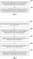
- Fig. 2 shows a schematic flowchart of a method for detecting an obstacle according to an embodiment of the present disclosure.
- a current image may be acquired, wherein the current image may include at least one obstacle object of at least one obstacle located on a predetermined plane.
- the current image may be a road monitoring image acquired by a roadside device. In some implementations, the current image may be a photo acquired by a roadside device. In some other implementations, the current image may also be a video frame in a video acquired by a roadside device.
- a position of an obstacle on a road may be monitored by utilizing the monitoring image acquired by the roadside device.
- the predetermined plane may be the ground plane. That is, the obstacle in the current image is located on the ground plane.
- the current image may be acquired using a monocular camera.
- determining a position of an object in an image in a three-dimensional world coordinate system by utilizing the image acquired using the monocular camera is under constraint.
- a pixel coordinate of the object in the image corresponds to a ray in the world coordinate system. That is, pixel coordinates of all points, located on the ray in the three-dimensional world coordinate system, in the image acquired by the camera are the same.
- an equation for expressing a specific plane may be pre-calibrated in the image, the position of the object located on the specific plane in the image in the world coordinate system may be determined using the monocular camera.
- a position of a pixel point on the ground plane may be obtained by computing an intersection point of a ray corresponding to pixel coordinates of the pixel point and the ground plane.
- a transformation parameter between the current image and a template image may be determined based on current coordinates of a plurality of reference points on the predetermined plane in the current image and template coordinates of corresponding reference points for the plurality of reference points in the template image.
- a plane where the plurality of reference points are located and the predetermined plane where the obstacle is located correspond to the same plane.
- an image shot by the roadside device in an original external parameter state may be acquired as the template image before the roadside device is put into use.
- Original external parameters that is, offline external parameters
- the image shot by the roadside device may be processed based on the offline external parameters so as to determine a three-dimensional position of the obstacle in the image.
- the roadside device for acquiring images may shake or permanently move.
- the external parameters of the camera of the roadside device may change, but the ground plane equation is still calibrated based on the original external parameters of the camera which are determined offline.
- the precision of the position of the obstacle object, in the image determined by the ground plane equation calibrated based on the original external parameters of the camera, in the world coordinate system may be reduced.
- the transformation parameter between the current image and the template image may be determined based on image change between the template image and the current image.
- the transformation parameter between the current image and the template image is capable of reflecting changes of the current external parameters of the camera acquiring the current image relative to the original external parameters of the camera acquiring the template image.
- the pixel coordinates in the current image acquired by the roadside device by utilizing the current external parameters may be transformed into corresponding coordinates of respective pixel points in the image acquired by utilizing the offline external parameters, without specially determining specific change values of the external parameters.
- step S206 the position of the obstacle in the world coordinate system may be determined by utilizing the transformation parameter determined in step S204 and the pixel coordinates of the obstacle in the current image.
- Coordinate transformation may be performed on the pixel coordinates of the obstacle in the current image by utilizing the transformation parameter determined in step S204 to obtain corresponding pixel coordinates of the obstacle in the template image acquired by utilizing the offline external parameters.
- the transformation between the current image acquired by the roadside device and the template image acquired by the roadside device by utilizing the offline external parameters may be determined by utilizing the plurality of reference points in the images, thereby conveniently correcting errors caused by change of the external parameters of the roadside device due to external environments, and then, eliminating adverse effects brought for the position detection of the obstacle in the acquired images due to the fact that the external parameters actually change, but are not recalibrated in the camera.
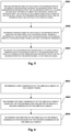
- Fig. 3 shows a schematic flowchart for determining a transformation parameter between a current image and a template image (such as above-mentioned step S204) according to an embodiment of the present disclosure.
- the current coordinates of the reference points may be obtained based on the template coordinates without knowing the change of the external parameters of the camera, thereby correcting the errors, caused by the change of the external parameters of the camera, in an image processing manner.
- the current coordinates of the plurality of reference points in the current image may be determined based on the template image and the current image and based on the template coordinates of the corresponding reference points in the template image.
- the plurality of reference points in the template image acquired by the roadside device may be points on a marker line (such as a lane line, a stop line or a turning marker line) on a road surface.
- the reference points may be angular points of the lane line, the stop line or the turning marker line.
- the angular points described herein may refer to intersection points of line segments included in graphs for representing the lane line, the stop line or the turning marker line on a road.
- the reference points may be determined by utilizing the graph of the marker line on the ground.
- the transformation parameter between the current image and the template image may be determined by utilizing change of the reference points in the current image relative to the corresponding reference points in the template image.
- a first offset of each reference point in the current image relative to the corresponding reference point in the template image may be determined by utilizing an optical flow tracking method.
- the current coordinates of the reference points may be determined based on the template coordinates of the reference points in the template image and the first offset. By using the optical flow tracking method, positions of the reference points in the current image may be conveniently determined.
- the optical flow tracking method may be used for tracking the motion of points in an image.
- An optical flow may be motion of a target caused when the target, scenario or camera moves between two frame images.
- the optical flow is capable of reflecting image change formed by motion within a certain time interval, thereby determining motion directions and rates of the points in the image.
- the motion of the plurality of reference points in the current image relative to the corresponding reference points in the template image may be determined, and the first offset generated when the plurality of reference points move from corresponding positions in the template image to positions in the current image may be determined.
- the current coordinates of the reference points in the current image may be obtained by utilizing the template coordinates of the corresponding reference points and a motion vector determined by utilizing the first offset.
- the transformation parameter between the current image and the template image may be determined based on transformation between the current coordinates of the plurality of reference points and the template coordinates of the corresponding reference points.
- the transformation parameter may be used for transforming a plane where the plurality of reference points in the current image are located into a plane where the corresponding reference points in the template image are located.
- Positional differences of the reference points between the current image and the template image are generated by the change of the external parameters of the camera due to influences from the external environments.
- the rotation and/or translation of the camera in the world coordinate system occurs to result in the change of positions of the reference points in the image. Therefore, a transformation parameter of the plane where the reference points are located may be computed as the transformation parameter between the current image and the template image based on a manner of coordinate transformation.
- the transformation parameter may be a homographic matrix.
- the homographic matrix may be used for describing rotation of an image acquiring device or a transformation relationship between planes.
- the reference points are located on the ground. Therefore, a transformation relationship between a ground plane in the current image and a ground plane in the template image may be computed by utilizing the template coordinates and ground coordinates of the reference points.
- a homographic transformation parameter may be a homographic matrix with 8 degrees of freedom and 3 ⁇ 3 dimensions.
- the homographic matrix may be computed by utilizing at least four matching point pairs in the case that the reference points in the template image and the corresponding reference points in the current image are regarded as a pair of matching points.
- a process of computing a coefficient of the homographic matrix is converted into a process of solving an over-determined equation set, the coefficient of the homographic matrix may be determined by utilizing the least square solution of the over-determined equation set. The larger the number of the matching points used in the computing process is, the higher the accuracy of the homographic matrix obtained by computation is.
- Fig. 4 shows a schematic flowchart for determining a transformation parameter between a current image and a template image based on current coordinates of a plurality of reference points and template coordinates of corresponding reference points (such as above-mentioned step S304) according to an embodiment of the present disclosure.
- the reference points with greater errors may be removed, so that the accuracy of the transformation parameter is improved.
- the coefficient of the computed homographic matrix is not directly determined as the transformation parameter between the current image and the template image by utilizing the matching points formed by the current coordinates of the plurality of reference points and the template coordinates of the corresponding reference points.
- the plurality of reference points may be screened using the method as shown in Fig. 4 to obtain a subset of the plurality of reference points suitable for determining the above-mentioned transformation parameter.
- a candidate transformation parameter may be determined by utilizing the current coordinates of the plurality of reference points and the template coordinates.
- the coefficient in the homographic matrix may be computed as the candidate transformation parameter by utilizing the matching point pairs formed by the current coordinates of the plurality of reference points and the template coordinates of the corresponding reference points.
- step S402 coordinate transformation may be performed on the current coordinates of the plurality of reference points by utilizing the candidate transformation parameter to obtain first transformation coordinates of the plurality of reference points.
- the first transformation coordinates obtained by performing coordinate transformation on the current coordinates of the plurality of reference points by utilizing the candidate transformation parameter should be the same as the template coordinates of the corresponding reference points in the template image.
- the first transformation coordinates obtained by performing coordinate transformation on the current coordinates of the plurality of reference points by utilizing the candidate transformation parameter should be the same as the template coordinates of the corresponding reference points in the template image.
- there are greater errors in the current coordinates, determined using the optical flow tracking method, of the reference points in the current image there are also greater errors between the first transformation coordinates of the reference points obtained in step S402 and the template coordinates.
- step S403 re-projection errors of the first transformation coordinates of the plurality of reference points relative to corresponding template coordinates may be determined.
- a first subset of the plurality of reference points may be determined by utilizing the re-projection errors determined in step S403, wherein reference points in the first subset have re-projection errors smaller than an error threshold.
- the transformation parameter may be determined by utilizing current coordinates of the reference points in the first subset and template coordinates of corresponding reference points for the reference points in the first subset, in the template image.
- the current coordinates of the reference points may be transformed by utilizing the candidate transformation parameter, so that differences of the coordinates, obtained by utilizing the candidate transformation parameter, of the reference points in the template image and the pre-calibrated template coordinates are compared, and reference points with greater differences are removed.
- the transformation parameter between the current image and the template image may be recomputed by utilizing reference points with few differences.
- Fig. 5 shows another schematic flowchart for determining a transformation parameter between a current image and a template image based on current coordinates of a plurality of reference points and template coordinates of corresponding reference points (such as above-mentioned steps S304) according to an embodiment of the present disclosure.
- the reference points with greater errors may be removed, so that the accuracy of the transformation parameter may be improved.
- a second offset between the reference point and a reference point corresponding to the reference point may be determined by utilizing the similarity between a current picture block, centered at the reference point, in the current image and a template picture block, centered at the corresponding reference point, in the template image.
- the current picture block and the template picture block may be picture blocks with pixels of which lengths and widths are respectively 101.
- the second offset of the reference point may be determined by computing the similarity between the current picture block and the template picture block. In some implementations, the second offset may be determined by computing the phase-based similarity between the current picture block and the template picture block. It can be understood by the skilled in the art that the similarity between the current picture block and the template picture block may also be determined using any other image processing methods if only such similarity may indicate the offset of the reference point.
- a second subset of the plurality of reference points may be determined based on the first offset and the second offset, wherein a difference of the first offset and the second offset of reference points in the second subset is smaller than a difference threshold.
- the reference points in the first subset may be further screened by utilizing the second offset determined in step S501. If the difference of the first offset and the second offset is greater than the difference threshold, the position of the reference point may be regarded as being overwhelming. Therefore, such reference point may be removed when the transformation parameter is computed.
- the transformation parameter may be determined by utilizing current coordinates of the reference points in the second subset and template coordinates of corresponding reference points for the reference points in the second subset, in the template image.
- the steps described in Fig. 5 may be performed on the reference points in the first subset to obtain the second subset.
- the second subset may be a subset of the first subset.
- Fig. 6 shows a schematic flowchart of a process for determining a position of an obstacle in a world coordinate system by utilizing the transformation parameter and pixel coordinates of an obstacle object in the current image (such as above-mentioned step S206) according to an embodiment of the present disclosure. Due to the fact that the obstacle and reference points are located on the same plane, coordinates of the obstacle object in the current image may be transformed on a template image conveniently by utilizing the transformation parameter computed using the reference points, and therefore, three-dimensional coordinates of the obstacle in the world coordinate system may be determined.
- step S602 a first coordinate of the obstacle object in the current image may be determined.
- the current image may be processed using a target detection algorithm, so that the obstacle object representing the obstacle in the current image is recognized.
- the obstacle may be a pedestrian or vehicle.
- a target box of the obstacle object existing in the current image may be recognized using the target detection algorithm, bottom central point coordinates for indicating the obstacle object may be determined as the first coordinates on the target box. For example, the bottom central point coordinates for indicating the obstacle object may be determined on the target box based on the type of the obstacle.
- a model for realizing the target detection algorithm may be trained, so that the model may learn a position of a bottom central point of the obstacle object, and the position of the bottom central point of the obstacle object may be directly determined by utilizing a result output by the model.
- the first coordinate of the obstacle may be transformed based on the transformation parameter to obtain a second coordinate of the obstacle.
- the second coordinate of the obstacle object in the template image may be determined based on the first coordinates of the obstacle object in the current image by utilizing the transformation parameter determined using the method described by at least one accompanying drawing in Fig. 1 to Fig. 5 .
- step S606 the position of the obstacle in the world coordinate system may be determined based on the second coordinate of the obstacle object.
- a position of an obstacle in a camera coordinate system may be determined based on the second coordinates of the obstacle object by utilizing an equation for indicating the predetermined plane in the camera coordinate system.
- the position of the obstacle in the world coordinate system may be determined based on the position of the obstacle in the camera coordinate system.
- Depth information of the obstacle on the predetermined plane may be provided by utilizing an equation of the known predetermined plane.
- Fig. 7 shows a schematic diagram of reference points in an image according to an embodiment of the present disclosure.
- points on a marker line on a road may be determined as the reference points.
- points 701, 702, 703 and 705 are angular points of a lane line
- point 704 is an angular point of a turning marker line.
- Fig. 7 only shows the reference points 701 to 705, however, it can be understood that the skilled in the art may more points on the marker line shown in Fig. 7 may be determined as the reference points.
- Fig. 8A and Fig. 8B show schematic diagrams of a detection result of an obstacle.
- Fig. 8A shows obstacles, which are respectively recognized under the condition that cameras of two roadside devices shake, on a road in the case that correction is not performed.
- Boxes 801 and 803 correspond to detection positions, respectively detected by the two roadside devices, of the same vehicle on an actual road
- boxes 802 and 804 correspond to detection positions, respectively detected by the two roadside devices, of the other same vehicle on the actual road. Since the shake of the cameras is not corrected, positions of the obstacles (the vehicles) detected in images acquired by the two roadside devices are different. In this case, it may be considered in combination with the images acquired by the two roadside devices that there are four vehicles on an intersection, which is different from actual conditions.
- Fig. 8B shows obstacles, recognized under the condition that cameras of two roadside devices shake, on a road in the case that correction is performed. Since the shake of the cameras of the roadside devices has been corrected, the two roadside devices are capable of detecting the vehicles 801 and 802 on the same position at different shooting angles. Therefore, detection errors caused by camera shake are avoided.
- Fig. 9 shows a schematic block diagram of an apparatus for detecting an obstacle according to an embodiment of the present disclosure.
- the apparatus 900 for detecting the obstacle may include an image acquiring unit 910, a transformation determining unit 920 and an obstacle position determining unit 930.
- the image acquiring unit 910 may be configured to acquire a current image, wherein the current image includes at least one obstacle located on a predetermined plane.
- the transformation determining unit 920 may be configured to determine a transformation parameter between the current image and a template image based on current coordinates of a plurality of reference points on the predetermined plane in the current image and template coordinates of corresponding reference points for the plurality of reference points, in the template image.
- the obstacle position determining unit 930 may be configured to determine a position of the obstacle in a world coordinate system by utilizing the transformation parameter and pixel coordinates of the obstacle object in the current image.
- the transformation determining unit may include: a coordinate determining subunit, configured to determine the current coordinates of the plurality of reference points in the current image based on the template image and the current image and based on the template coordinates of the corresponding reference points in the template image; and a parameter determining unit, configured to determine the transformation parameter between the current image and the template image based on transformation between the current coordinates of the plurality of reference points and the template coordinates of the corresponding reference points.
- the coordinate determining subunit may include: a tracking subunit, configured to determine a first offset of the reference points in the current image relative to the corresponding reference points in the template image using an optical flow tracking method; and an offset subunit, configured to determine the current coordinates of the reference points based on the first offset of the reference points and the template coordinates.
- the parameter determining unit may include: a candidate transformation determining subunit, configured to determine a candidate transformation parameter by utilizing the current coordinates of the plurality of reference points and the template coordinates; a transformation subunit, configured to perform coordinate transformation on the current coordinates of the plurality of reference points by utilizing the candidate transformation parameter to obtain first transformation coordinates of the plurality of reference points; an error determining subunit, configured to determine re-projection errors of the first transformation coordinates of the plurality of reference points relative to corresponding template coordinates; a screening subunit, configured to determine a first subset of the plurality of reference points, wherein reference points in the first subset have re-projection errors smaller than an error threshold; and a transformation parameter determining subunit, configured to determine the transformation parameter by utilizing current coordinates of the reference points in the first subset and template coordinates of corresponding reference points for the reference points in the first subset, in the template image.
- the parameter determining unit may include: a similarity determining subunit, configured to, for each reference point of the plurality of reference points, determine a second offset between the reference point and a corresponding reference point for the reference point by utilizing the similarity between a current picture block, centered at the reference point, in the current image and a template picture block, centered at the corresponding reference point , in the template image; a screening subunit, configured to determine a second subset of the plurality of reference points based on the first offset and the second offset, wherein a difference of the first offset and the second offset of reference points in the second subset is smaller than a difference threshold; and a transformation parameter determining subunit, configured to determine the transformation parameter by utilizing current coordinates of the reference points in the second subset and template coordinates of corresponding reference points for the reference points in the second subset, in the template image.
- a similarity determining subunit configured to, for each reference point of the plurality of reference points, determine a second offset between the reference point and a corresponding reference
- the obstacle position determining unit may include: a first coordinate determining subunit, configured to determine a first coordinate of the obstacle object in the current image; a second coordinate determining subunit, configured to transform the first coordinate of the obstacle object based on the transformation parameter to obtain a second coordinate of the obstacle object; and a world coordinate determining subunit, configured to determine the position of the obstacle in the world coordinate system based on the second coordinate of the obstacle object.
- the transformation between the current image acquired by the roadside device and the template image acquired by the roadside device by utilizing the offline external parameters may be determined by utilizing the plurality of reference points in the images, thereby conveniently correcting errors caused by change of the external parameters of the roadside device due to external environments, and then, eliminating adverse effects brought for the position detection of the obstacle in the acquired images due to the fact that the external parameters change.
- an electronic device including: at least one processor; and a memory in communication connection with the at least one processor.
- the memory stores an instruction executable for the at least one processor, and the instruction is executed by the at least one processor, so that the at least one processor is enabled to execute the method as mentioned in combination with Fig. 1 to Fig. 6 .
- a roadside device including the electronic device as mentioned previously.
- a cloud control platform including the electronic device as mentioned previously.
- a non-transitory computer-readable storage medium storing a computer instruction, wherein the computer instruction is used to enable a computer to execute the method as mentioned in combination with Fig. 1 to Fig. 6 .
- a computer program product including a computer program, wherein when the computer program is executed by a processor, the method as mentioned in combination with Fig. 1 to Fig. 6 is implemented.
- FIG. 10 a structural block diagram of an electronic device 1000 which may be used as a mobile terminal of the present disclosure will be described from now on, and it is an example of a hardware device which may be applied to various aspects of the present disclosure.
- the electronic device is intended to represent various forms of digital-electronic computer devices such as a laptop computer, a desk computer, a worktable, a personal digital assistant, a server, a blade server, a large-scale computer and other suitable computers.
- the electronic device may also represent various forms of mobile devices such as a personal digital assistant, a cell phone, a smart phone, a wearable device and other types of computing apparatuses.
- Components as shown herein, their connection and relationship as well as their functions are only used as examples, and are not intended to limit the implementations, described and/or claimed herein, of the present disclosure.
- the device 1000 includes a computing unit 1001 which may execute various appropriate actions and processing according to a computer program stored in a read only memory (ROM) 1002 or a computer program loaded from a storage unit 1008 to a random access memory (RAM) 1003.
- ROM read only memory
- RAM random access memory
- various programs and data required for operation of the device 1000 may also be stored.
- the computing unit 1001, the ROM 1002 and the RAM 1003 are connected with one another by a bus 1004.
- An input/output (I/O) interface 1005 is also connected to the bus 1004.
- a plurality of components, including an input unit 1006, an output unit 1007, the storage unit 1008 and a communication unit 1009, in the device 1000 are connected to the input/output (I/O) interface 1005.
- the input unit 1006 may be any type of device capable of inputting information to the device 1000.
- the input unit 1006 may receive input figure or character information and generate key signal input related to user setting and/or functional control of the electronic device, and may include, but is not limited to a mouse, a keyboard, a touch screen, a track pad, a trackball, an operating lever, a microphone and/or a remote controller.
- the output unit 1007 may be any type of device capable of representing information and may include, but is not limited to a display, a loudspeaker, a video/audio output terminal, a vibrator and/or a printer.
- the storage unit 1008 may include, but is not limited to a magnetic disk and an optical disk.
- the communication unit 1009 allows the device 1000 to exchange information/data with other devices by utilizing a computer network such as internet, and/or various telecommunication networks, and may include, but is not limited to a modem, a network card, an infrared communication device, a wireless communication transceiver and/or a chip set, such as a Bluetooth TM device, a 1302.11 device, a WiFi device, a WiMax device, a cellular communication device and/or analogues thereof.
- the computing unit 1001 may be various general-purpose or special-purpose processing components with processing and computing capacities. Some examples of the computing unit 1001 include, but are not limited to a central processing unit (CPU), a graphic processing unit (GPU), various special-purpose artificial intelligent (AI) computing chips, various computing units for running machine learning model algorithms, a digital signal processor (DSP), and any appropriate processor, controller and microcontroller.
- the computing unit 1001 performs all the methods and processing described above, such as the method for detecting the obstacle according to the embodiment of the present disclosure.
- the detection of the obstacle may be implemented as a computer software program which is visibly included in a machine-reachable medium such as the storage unit 1008.
- part or all of the computer program may be loaded and/or installed on the device 1000 by utilizing the ROM 1002 and/or the communication unit 1009.
- the computer program When the computer program is loaded on the RAM 1003 and is executed by the computing unit 1001, one or more steps of the method described above may be performed.
- the computing unit 1001 may be configured to execute, in any other appropriate manners, the method for detecting the obstacle.
- Various implementations of the above system and technology described herein may be implemented in a digital electronic circuit system, an integrated circuit system, a field-programmable gate array (FPGA), an application-specific integrated circuit (ASIC), an application-specific standard product (ASSP), a system of a system on chip (SOC), a complex programmable logic device (CPLD), computer hardware, firmware, software, and/or their combinations.
- FPGA field-programmable gate array
- ASIC application-specific integrated circuit
- ASSP application-specific standard product
- SOC system of a system on chip
- CPLD complex programmable logic device
- the various implementations modes may include implementation in one or more computer programs, the one or more computer programs may be executed and/or explained on a programmable system including at least one programmable processor, the programmable processor may be a special-purpose or general-purpose programmable processor, and may receive data and instructions from a storage system, at least one input apparatus and at least one output apparatus and transmit data and instructions to the storage system, the at least one input apparatus and the at least one output apparatus.
- Program codes for implementing the method provided by the present disclosure may be compiled by adopting any combinations of one or more programming languages. These program codes may be provided to a processor or controller of a general-purpose computer, a specific-purpose computer or other programmable data processing apparatuses, so that functions and/or operations specified in the flow diagrams and/or block diagrams are implemented when the program codes are executed by the processor or the controller.
- the program codes may be completely executed on a machine, partially executed on the machine, partially executed as an independent software packet on the machine and partially executed on a remote machine, or completely executed on the remote machine or a server.
- the machine-readable medium may be a tangible medium which may include or store programs to be used by an instruction execution system, apparatus or device or to be used by the instruction execution system, apparatus or device in combination.
- the machine-readable medium may be a machine-readable signal medium or a machine-readable storage medium.
- the machine-readable medium may include, but is not limited to electronic, magnetic, optical, electromagnetic, infrared or semiconductor system, apparatus or device, or any appropriate combination of the above.
- machine-readable storage medium may include electric connection based on one or more lines, a portable computer disk, a hard disk, a random access memory (RAM), a read-only memory (ROM), an electrically programmable read-only memory (EPROM or flash memory), an optical fiber, a portable compact disc read-only memory (CD-ROM), an optical storage device, a magnetic storage device, or any appropriate combination of the above.
- RAM random access memory
- ROM read-only memory
- EPROM or flash memory electrically programmable read-only memory
- CD-ROM compact disc read-only memory
- magnetic storage device a magnetic storage device
- the system and technology described herein may be implemented on a computer.
- the computer is provided with a display apparatus (such as a CRT (Cathode Ray Tube) or an LCD (Liquid Crystal Display) monitor) for displaying information to the user; and a keyboard and a pointing apparatus (such as a mouse or a trackball), wherein the user may provide input to the computer by the keyboard and the pointing apparatus.
- a display apparatus such as a CRT (Cathode Ray Tube) or an LCD (Liquid Crystal Display) monitor
- a keyboard and a pointing apparatus such as a mouse or a trackball
- Other kinds of apparatuses may also be used for providing interaction with the user.
- a feedback provided to the user may be any form of sensory feedback (such as a visual feedback, an auditory feedback or a tactile feedback).
- the input from the user may be received in any manner (including sound input, voice input or tactile input).
- the system and technology described herein may be implemented in a computing system (such as a data server) including a background component, or a computing system (such as an application server) including a middleware component, or a computing system (such as a user computer provided with a graphical user interface or a web browser, wherein a user may interact, by utilizing the graphical user interface or the web browser, with the implementations of the system and the technology described herein) including a front end component, or a computing system including any combinations of the background component, the middleware component or the front end component.
- the components of the system may be interconnected by digital data communication in any manner or medium (such as a communication network). Examples of the communication network include a local area network (LAN), a wide area network (WAN) and an Internet.
- LAN local area network
- WAN wide area network
- Internet an Internet
- the computer system may include a client and a server.
- the client and the server are generally far away from each other and generally interact through the communication network.
- a relationship between the client and the server is generated by a computer program running on a corresponding computer and having a client-server relationship.
Landscapes
- Engineering & Computer Science (AREA)
- Theoretical Computer Science (AREA)
- General Physics & Mathematics (AREA)
- Physics & Mathematics (AREA)
- Computer Vision & Pattern Recognition (AREA)
- Multimedia (AREA)
- Software Systems (AREA)
- Artificial Intelligence (AREA)
- Evolutionary Computation (AREA)
- Computing Systems (AREA)
- Medical Informatics (AREA)
- Data Mining & Analysis (AREA)
- General Engineering & Computer Science (AREA)
- General Health & Medical Sciences (AREA)
- Databases & Information Systems (AREA)
- Health & Medical Sciences (AREA)
- Mathematical Physics (AREA)
- Life Sciences & Earth Sciences (AREA)
- Bioinformatics & Cheminformatics (AREA)
- Bioinformatics & Computational Biology (AREA)
- Evolutionary Biology (AREA)
- Traffic Control Systems (AREA)
- Image Analysis (AREA)
Applications Claiming Priority (1)
| Application Number | Priority Date | Filing Date | Title |
|---|---|---|---|
| CN202011558835.0A CN112560769B (zh) | 2020-12-25 | 2020-12-25 | 用于检测障碍物的方法、电子设备、路侧设备和云控平台 |
Publications (3)
| Publication Number | Publication Date |
|---|---|
| EP3961583A2 true EP3961583A2 (de) | 2022-03-02 |
| EP3961583A3 EP3961583A3 (de) | 2022-06-22 |
| EP3961583B1 EP3961583B1 (de) | 2024-08-07 |
Family
ID=75032413
Family Applications (1)
| Application Number | Title | Priority Date | Filing Date |
|---|---|---|---|
| EP21217337.1A Active EP3961583B1 (de) | 2020-12-25 | 2021-12-23 | Verfahren zum erkennen von hindernissen, elektronischen geräten, strassenrandgeräten und cloud-steuerungsplattform |
Country Status (5)
| Country | Link |
|---|---|
| US (1) | US12125287B2 (de) |
| EP (1) | EP3961583B1 (de) |
| JP (1) | JP7351892B2 (de) |
| KR (1) | KR102694715B1 (de) |
| CN (1) | CN112560769B (de) |
Cited By (1)
| Publication number | Priority date | Publication date | Assignee | Title |
|---|---|---|---|---|
| KR20240167573A (ko) * | 2023-05-20 | 2024-11-27 | 성승택 | 상대 깊이 맵 및 옵티컬 플로우를 활용한 절대 깊이 추정 방법 |
Families Citing this family (9)
| Publication number | Priority date | Publication date | Assignee | Title |
|---|---|---|---|---|
| CN113312979B (zh) * | 2021-04-30 | 2024-04-16 | 阿波罗智联(北京)科技有限公司 | 图像处理方法、装置、电子设备、路侧设备及云控平台 |
| CN113819890B (zh) * | 2021-06-04 | 2023-04-14 | 腾讯科技(深圳)有限公司 | 测距方法、装置、电子设备及存储介质 |
| CN114740854A (zh) * | 2022-04-11 | 2022-07-12 | 北京京东乾石科技有限公司 | 一种机器人避障控制方法和装置 |
| CN116563378B (zh) * | 2023-03-24 | 2026-04-03 | 浙江商汤科技开发有限公司 | 一种视觉定位方法、装置、电子设备及存储介质 |
| WO2024221375A1 (zh) * | 2023-04-28 | 2024-10-31 | 宁德时代新能源科技股份有限公司 | 定位待检测图像中目标物的方法、装置和存储介质 |
| KR20250092451A (ko) * | 2023-12-15 | 2025-06-24 | 포스코홀딩스 주식회사 | 장애물 검출 장치 및 그 방법 |
| CN117831004B (zh) * | 2024-01-31 | 2025-10-17 | 广东工业大学 | 无人驾驶方程式赛车障碍物检测方法、装置、设备及介质 |
| CN118314359B (zh) * | 2024-03-11 | 2025-05-13 | 广东国工智能科技有限公司 | 高速机械执行末端防抖动计算调控方法、系统及加工系统 |
| JP7753424B2 (ja) * | 2024-03-13 | 2025-10-14 | ソフトバンク株式会社 | 情報処理装置、システム、情報処理方法及び制御プログラム |
Family Cites Families (33)
| Publication number | Priority date | Publication date | Assignee | Title |
|---|---|---|---|---|
| JPH10143659A (ja) | 1996-11-06 | 1998-05-29 | Komatsu Ltd | 物体検出装置 |
| JP2001319218A (ja) | 2000-02-29 | 2001-11-16 | Hitachi Ltd | 画像監視装置 |
| JP2005182504A (ja) | 2003-12-19 | 2005-07-07 | Matsushita Electric Ind Co Ltd | 駐車支援システム |
| JP4406381B2 (ja) * | 2004-07-13 | 2010-01-27 | 株式会社東芝 | 障害物検出装置及び方法 |
| JP4297501B2 (ja) * | 2004-08-11 | 2009-07-15 | 国立大学法人東京工業大学 | 移動体周辺監視装置 |
| JP4807277B2 (ja) | 2007-02-13 | 2011-11-02 | 富士ゼロックス株式会社 | 画像処理装置及び画像処理プログラム |
| JP5034733B2 (ja) | 2007-07-13 | 2012-09-26 | カシオ計算機株式会社 | 特徴点追跡装置及びプログラム |
| JP4623200B2 (ja) | 2008-10-27 | 2011-02-02 | ソニー株式会社 | 画像処理装置、画像処理方法およびプログラム |
| CN101441076B (zh) * | 2008-12-29 | 2010-06-02 | 东软集团股份有限公司 | 一种检测障碍物的方法和装置 |
| JP2010287153A (ja) | 2009-06-15 | 2010-12-24 | Renesas Electronics Corp | 混雑状況判定装置と混雑状況判定方法並びにプログラム |
| US8417062B2 (en) | 2009-10-19 | 2013-04-09 | Ut-Battelle, Llc | System and method for stabilization of fisheye video imagery |
| JP5549605B2 (ja) | 2011-01-13 | 2014-07-16 | 新日鐵住金株式会社 | 視線位置検出装置、視線位置検出方法、及びコンピュータプログラム |
| JP2013061773A (ja) * | 2011-09-13 | 2013-04-04 | Ricoh Co Ltd | 前方障害物検知装置 |
| KR101489468B1 (ko) * | 2013-06-28 | 2015-02-03 | 주식회사 아이티엑스시큐리티 | 호모그래피 기반 카메라 영상 보정 장치 및 방법 |
| JP6211407B2 (ja) | 2013-12-06 | 2017-10-11 | 株式会社デンソーアイティーラボラトリ | 画像検索システム、画像検索装置、検索サーバ装置、画像検索方法、及び画像検索プログラム |
| CN104299244B (zh) * | 2014-09-26 | 2017-07-25 | 东软集团股份有限公司 | 基于单目相机的障碍物检测方法及装置 |
| US10248124B2 (en) * | 2016-07-21 | 2019-04-02 | Mobileye Vision Technologies, Inc. | Localizing vehicle navigation using lane measurements |
| CN110419211B (zh) | 2017-03-15 | 2020-12-22 | 三菱电机株式会社 | 信息处理装置、信息处理方法和计算机可读的存储介质 |
| CN108682038B (zh) * | 2018-04-27 | 2021-12-14 | 腾讯科技(深圳)有限公司 | 位姿确定方法、装置及存储介质 |
| CN108830257A (zh) * | 2018-06-29 | 2018-11-16 | 电子科技大学 | 一种基于单目光流的潜在障碍物检测方法 |
| JP7220530B2 (ja) | 2018-07-18 | 2023-02-10 | アマノ株式会社 | 駐車場管理システム、駐車場管理装置、駐車場管理方法、及びプログラム |
| CN113486797B (zh) | 2018-09-07 | 2023-08-11 | 百度在线网络技术(北京)有限公司 | 无人车位置检测方法、装置、设备、存储介质及车辆 |
| CN111754580A (zh) * | 2019-03-28 | 2020-10-09 | 阿里巴巴集团控股有限公司 | 一种摄像头标定方法、路侧感知设备和智慧交通系统 |
| JP7334058B2 (ja) | 2019-05-09 | 2023-08-28 | エヌ・ティ・ティ・コミュニケーションズ株式会社 | 幾何パラメータ推定装置、幾何パラメータ推定システム、幾何パラメータ推定方法及びコンピュータプログラム |
| CN110146869B (zh) * | 2019-05-21 | 2021-08-10 | 北京百度网讯科技有限公司 | 确定坐标系转换参数的方法、装置、电子设备和存储介质 |
| CN110213488B (zh) * | 2019-06-06 | 2022-01-18 | 腾讯科技(深圳)有限公司 | 一种定位方法及相关设备 |
| CN110717457A (zh) | 2019-10-10 | 2020-01-21 | 郑州迈拓信息技术有限公司 | 用于车辆的行人位姿解算方法 |
| CN110728720B (zh) * | 2019-10-21 | 2023-10-13 | 阿波罗智能技术(北京)有限公司 | 用于相机标定的方法、装置、设备和存储介质 |
| CN111046762A (zh) * | 2019-11-29 | 2020-04-21 | 腾讯科技(深圳)有限公司 | 一种对象定位方法、装置电子设备及存储介质 |
| CN111612760B (zh) * | 2020-05-20 | 2023-11-17 | 阿波罗智联(北京)科技有限公司 | 用于检测障碍物的方法和装置 |
| CN111578839B (zh) * | 2020-05-25 | 2022-09-20 | 阿波罗智联(北京)科技有限公司 | 障碍物坐标处理方法、装置、电子设备及可读存储介质 |
| CN111767843B (zh) | 2020-06-29 | 2024-01-02 | 阿波罗智联(北京)科技有限公司 | 三维位置预测方法、装置、设备以及存储介质 |
| CN111998772B (zh) | 2020-08-05 | 2021-11-16 | 浙江大学 | 一种基于激光与单目视觉融合的像素级目标定位方法 |
-
2020
- 2020-12-25 CN CN202011558835.0A patent/CN112560769B/zh active Active
-
2021
- 2021-12-14 KR KR1020210178984A patent/KR102694715B1/ko active Active
- 2021-12-22 US US17/560,246 patent/US12125287B2/en active Active
- 2021-12-23 EP EP21217337.1A patent/EP3961583B1/de active Active
- 2021-12-24 JP JP2021210732A patent/JP7351892B2/ja active Active
Cited By (1)
| Publication number | Priority date | Publication date | Assignee | Title |
|---|---|---|---|---|
| KR20240167573A (ko) * | 2023-05-20 | 2024-11-27 | 성승택 | 상대 깊이 맵 및 옵티컬 플로우를 활용한 절대 깊이 추정 방법 |
Also Published As
| Publication number | Publication date |
|---|---|
| US20220114813A1 (en) | 2022-04-14 |
| US12125287B2 (en) | 2024-10-22 |
| JP7351892B2 (ja) | 2023-09-27 |
| EP3961583B1 (de) | 2024-08-07 |
| EP3961583A3 (de) | 2022-06-22 |
| JP2022034034A (ja) | 2022-03-02 |
| KR20220004604A (ko) | 2022-01-11 |
| KR102694715B1 (ko) | 2024-08-12 |
| CN112560769A (zh) | 2021-03-26 |
| CN112560769B (zh) | 2023-08-29 |
Similar Documents
| Publication | Publication Date | Title |
|---|---|---|
| EP3961583B1 (de) | Verfahren zum erkennen von hindernissen, elektronischen geräten, strassenrandgeräten und cloud-steuerungsplattform | |
| US11227395B2 (en) | Method and apparatus for determining motion vector field, device, storage medium and vehicle | |
| CN110246182B (zh) | 基于视觉的全局地图定位方法、装置、存储介质和设备 | |
| EP3627180A1 (de) | Sensorkalibrationsverfahren und -vorrichtung, computervorrichtung, medium und fahrzeug | |
| CN113887400B (zh) | 障碍物检测方法、模型训练方法、装置及自动驾驶车辆 | |
| CN111121754A (zh) | 移动机器人定位导航方法、装置、移动机器人及存储介质 | |
| CN111127563A (zh) | 联合标定方法、装置、电子设备及存储介质 | |
| WO2020172875A1 (zh) | 道路结构信息的提取方法、无人机及自动驾驶系统 | |
| US20240221215A1 (en) | High-precision vehicle positioning | |
| CN113989450A (zh) | 图像处理方法、装置、电子设备和介质 | |
| CN111563450B (zh) | 数据处理方法、装置、设备及存储介质 | |
| EP4019900A1 (de) | Navigationssystem mit parkplatzidentifikationsmechanismus und betriebsverfahren dafür | |
| CN115578433B (zh) | 图像处理方法、装置、电子设备及存储介质 | |
| CN114419564B (zh) | 车辆位姿检测方法、装置、设备、介质及自动驾驶车辆 | |
| CN110660098A (zh) | 基于单目视觉的定位方法和装置 | |
| CN112509126A (zh) | 三维物体检测的方法、装置、设备及存储介质 | |
| US20250329116A1 (en) | Positioning method and apparatus, electronic device, computer-readable storage medium, and computer program product | |
| CN115164936A (zh) | 高精地图制作中用于点云拼接的全局位姿修正方法及设备 | |
| CN111578839A (zh) | 障碍物坐标处理方法、装置、电子设备及可读存储介质 | |
| CN113628284B (zh) | 位姿标定数据集生成方法、装置、系统、电子设备及介质 | |
| CN115063490A (zh) | 车辆相机外参标定方法、装置、电子设备及存储介质 | |
| CN114140512A (zh) | 一种图像处理方法以及相关设备 | |
| CN115578432B (zh) | 图像处理方法、装置、电子设备及存储介质 | |
| CN115294234B (zh) | 图像的生成方法、装置、电子设备和存储介质 | |
| CN111612851A (zh) | 用于标定相机的方法、装置、设备以及存储介质 |
Legal Events
| Date | Code | Title | Description |
|---|---|---|---|
| PUAI | Public reference made under article 153(3) epc to a published international application that has entered the european phase |
Free format text: ORIGINAL CODE: 0009012 |
|
| STAA | Information on the status of an ep patent application or granted ep patent |
Free format text: STATUS: REQUEST FOR EXAMINATION WAS MADE |
|
| 17P | Request for examination filed |
Effective date: 20211223 |
|
| AK | Designated contracting states |
Kind code of ref document: A2 Designated state(s): AL AT BE BG CH CY CZ DE DK EE ES FI FR GB GR HR HU IE IS IT LI LT LU LV MC MK MT NL NO PL PT RO RS SE SI SK SM TR |
|
| PUAL | Search report despatched |
Free format text: ORIGINAL CODE: 0009013 |
|
| AK | Designated contracting states |
Kind code of ref document: A3 Designated state(s): AL AT BE BG CH CY CZ DE DK EE ES FI FR GB GR HR HU IE IS IT LI LT LU LV MC MK MT NL NO PL PT RO RS SE SI SK SM TR |
|
| RIC1 | Information provided on ipc code assigned before grant |
Ipc: G06V 10/75 20220101ALI20220519BHEP Ipc: G06V 20/58 20220101AFI20220519BHEP |
|
| STAA | Information on the status of an ep patent application or granted ep patent |
Free format text: STATUS: EXAMINATION IS IN PROGRESS |
|
| 17Q | First examination report despatched |
Effective date: 20230227 |
|
| GRAP | Despatch of communication of intention to grant a patent |
Free format text: ORIGINAL CODE: EPIDOSNIGR1 |
|
| STAA | Information on the status of an ep patent application or granted ep patent |
Free format text: STATUS: GRANT OF PATENT IS INTENDED |
|
| INTG | Intention to grant announced |
Effective date: 20240228 |
|
| GRAS | Grant fee paid |
Free format text: ORIGINAL CODE: EPIDOSNIGR3 |
|
| GRAA | (expected) grant |
Free format text: ORIGINAL CODE: 0009210 |
|
| STAA | Information on the status of an ep patent application or granted ep patent |
Free format text: STATUS: THE PATENT HAS BEEN GRANTED |
|
| AK | Designated contracting states |
Kind code of ref document: B1 Designated state(s): AL AT BE BG CH CY CZ DE DK EE ES FI FR GB GR HR HU IE IS IT LI LT LU LV MC MK MT NL NO PL PT RO RS SE SI SK SM TR |
|
| REG | Reference to a national code |
Ref country code: GB Ref legal event code: FG4D |
|
| REG | Reference to a national code |
Ref country code: CH Ref legal event code: EP |
|
| REG | Reference to a national code |
Ref country code: IE Ref legal event code: FG4D |
|
| REG | Reference to a national code |
Ref country code: DE Ref legal event code: R096 Ref document number: 602021016776 Country of ref document: DE |
|
| P01 | Opt-out of the competence of the unified patent court (upc) registered |
Free format text: CASE NUMBER: APP_50125/2024 Effective date: 20240904 |
|
| REG | Reference to a national code |
Ref country code: LT Ref legal event code: MG9D |
|
| REG | Reference to a national code |
Ref country code: NL Ref legal event code: MP Effective date: 20240807 |
|
| PG25 | Lapsed in a contracting state [announced via postgrant information from national office to epo] |
Ref country code: NO Free format text: LAPSE BECAUSE OF FAILURE TO SUBMIT A TRANSLATION OF THE DESCRIPTION OR TO PAY THE FEE WITHIN THE PRESCRIBED TIME-LIMIT Effective date: 20241107 |
|
| REG | Reference to a national code |
Ref country code: AT Ref legal event code: MK05 Ref document number: 1711823 Country of ref document: AT Kind code of ref document: T Effective date: 20240807 |
|
| PG25 | Lapsed in a contracting state [announced via postgrant information from national office to epo] |
Ref country code: NL Free format text: LAPSE BECAUSE OF FAILURE TO SUBMIT A TRANSLATION OF THE DESCRIPTION OR TO PAY THE FEE WITHIN THE PRESCRIBED TIME-LIMIT Effective date: 20240807 Ref country code: FI Free format text: LAPSE BECAUSE OF FAILURE TO SUBMIT A TRANSLATION OF THE DESCRIPTION OR TO PAY THE FEE WITHIN THE PRESCRIBED TIME-LIMIT Effective date: 20240807 Ref country code: PL Free format text: LAPSE BECAUSE OF FAILURE TO SUBMIT A TRANSLATION OF THE DESCRIPTION OR TO PAY THE FEE WITHIN THE PRESCRIBED TIME-LIMIT Effective date: 20240807 Ref country code: GR Free format text: LAPSE BECAUSE OF FAILURE TO SUBMIT A TRANSLATION OF THE DESCRIPTION OR TO PAY THE FEE WITHIN THE PRESCRIBED TIME-LIMIT Effective date: 20241108 Ref country code: PT Free format text: LAPSE BECAUSE OF FAILURE TO SUBMIT A TRANSLATION OF THE DESCRIPTION OR TO PAY THE FEE WITHIN THE PRESCRIBED TIME-LIMIT Effective date: 20241209 |
|
| PG25 | Lapsed in a contracting state [announced via postgrant information from national office to epo] |
Ref country code: BG Free format text: LAPSE BECAUSE OF FAILURE TO SUBMIT A TRANSLATION OF THE DESCRIPTION OR TO PAY THE FEE WITHIN THE PRESCRIBED TIME-LIMIT Effective date: 20240807 |
|
| PG25 | Lapsed in a contracting state [announced via postgrant information from national office to epo] |
Ref country code: LV Free format text: LAPSE BECAUSE OF FAILURE TO SUBMIT A TRANSLATION OF THE DESCRIPTION OR TO PAY THE FEE WITHIN THE PRESCRIBED TIME-LIMIT Effective date: 20240807 |
|
| PG25 | Lapsed in a contracting state [announced via postgrant information from national office to epo] |
Ref country code: AT Free format text: LAPSE BECAUSE OF FAILURE TO SUBMIT A TRANSLATION OF THE DESCRIPTION OR TO PAY THE FEE WITHIN THE PRESCRIBED TIME-LIMIT Effective date: 20240807 Ref country code: IS Free format text: LAPSE BECAUSE OF FAILURE TO SUBMIT A TRANSLATION OF THE DESCRIPTION OR TO PAY THE FEE WITHIN THE PRESCRIBED TIME-LIMIT Effective date: 20241207 |
|
| PG25 | Lapsed in a contracting state [announced via postgrant information from national office to epo] |
Ref country code: HR Free format text: LAPSE BECAUSE OF FAILURE TO SUBMIT A TRANSLATION OF THE DESCRIPTION OR TO PAY THE FEE WITHIN THE PRESCRIBED TIME-LIMIT Effective date: 20240807 |
|
| PG25 | Lapsed in a contracting state [announced via postgrant information from national office to epo] |
Ref country code: ES Free format text: LAPSE BECAUSE OF FAILURE TO SUBMIT A TRANSLATION OF THE DESCRIPTION OR TO PAY THE FEE WITHIN THE PRESCRIBED TIME-LIMIT Effective date: 20240807 Ref country code: RS Free format text: LAPSE BECAUSE OF FAILURE TO SUBMIT A TRANSLATION OF THE DESCRIPTION OR TO PAY THE FEE WITHIN THE PRESCRIBED TIME-LIMIT Effective date: 20241107 |
|
| PG25 | Lapsed in a contracting state [announced via postgrant information from national office to epo] |
Ref country code: RS Free format text: LAPSE BECAUSE OF FAILURE TO SUBMIT A TRANSLATION OF THE DESCRIPTION OR TO PAY THE FEE WITHIN THE PRESCRIBED TIME-LIMIT Effective date: 20241107 Ref country code: PT Free format text: LAPSE BECAUSE OF FAILURE TO SUBMIT A TRANSLATION OF THE DESCRIPTION OR TO PAY THE FEE WITHIN THE PRESCRIBED TIME-LIMIT Effective date: 20241209 Ref country code: PL Free format text: LAPSE BECAUSE OF FAILURE TO SUBMIT A TRANSLATION OF THE DESCRIPTION OR TO PAY THE FEE WITHIN THE PRESCRIBED TIME-LIMIT Effective date: 20240807 Ref country code: NO Free format text: LAPSE BECAUSE OF FAILURE TO SUBMIT A TRANSLATION OF THE DESCRIPTION OR TO PAY THE FEE WITHIN THE PRESCRIBED TIME-LIMIT Effective date: 20241107 Ref country code: NL Free format text: LAPSE BECAUSE OF FAILURE TO SUBMIT A TRANSLATION OF THE DESCRIPTION OR TO PAY THE FEE WITHIN THE PRESCRIBED TIME-LIMIT Effective date: 20240807 Ref country code: LV Free format text: LAPSE BECAUSE OF FAILURE TO SUBMIT A TRANSLATION OF THE DESCRIPTION OR TO PAY THE FEE WITHIN THE PRESCRIBED TIME-LIMIT Effective date: 20240807 Ref country code: IS Free format text: LAPSE BECAUSE OF FAILURE TO SUBMIT A TRANSLATION OF THE DESCRIPTION OR TO PAY THE FEE WITHIN THE PRESCRIBED TIME-LIMIT Effective date: 20241207 Ref country code: HR Free format text: LAPSE BECAUSE OF FAILURE TO SUBMIT A TRANSLATION OF THE DESCRIPTION OR TO PAY THE FEE WITHIN THE PRESCRIBED TIME-LIMIT Effective date: 20240807 Ref country code: GR Free format text: LAPSE BECAUSE OF FAILURE TO SUBMIT A TRANSLATION OF THE DESCRIPTION OR TO PAY THE FEE WITHIN THE PRESCRIBED TIME-LIMIT Effective date: 20241108 Ref country code: FI Free format text: LAPSE BECAUSE OF FAILURE TO SUBMIT A TRANSLATION OF THE DESCRIPTION OR TO PAY THE FEE WITHIN THE PRESCRIBED TIME-LIMIT Effective date: 20240807 Ref country code: ES Free format text: LAPSE BECAUSE OF FAILURE TO SUBMIT A TRANSLATION OF THE DESCRIPTION OR TO PAY THE FEE WITHIN THE PRESCRIBED TIME-LIMIT Effective date: 20240807 Ref country code: BG Free format text: LAPSE BECAUSE OF FAILURE TO SUBMIT A TRANSLATION OF THE DESCRIPTION OR TO PAY THE FEE WITHIN THE PRESCRIBED TIME-LIMIT Effective date: 20240807 Ref country code: AT Free format text: LAPSE BECAUSE OF FAILURE TO SUBMIT A TRANSLATION OF THE DESCRIPTION OR TO PAY THE FEE WITHIN THE PRESCRIBED TIME-LIMIT Effective date: 20240807 |
|
| PG25 | Lapsed in a contracting state [announced via postgrant information from national office to epo] |
Ref country code: DK Free format text: LAPSE BECAUSE OF FAILURE TO SUBMIT A TRANSLATION OF THE DESCRIPTION OR TO PAY THE FEE WITHIN THE PRESCRIBED TIME-LIMIT Effective date: 20240807 Ref country code: SM Free format text: LAPSE BECAUSE OF FAILURE TO SUBMIT A TRANSLATION OF THE DESCRIPTION OR TO PAY THE FEE WITHIN THE PRESCRIBED TIME-LIMIT Effective date: 20240807 |
|
| PG25 | Lapsed in a contracting state [announced via postgrant information from national office to epo] |
Ref country code: EE Free format text: LAPSE BECAUSE OF FAILURE TO SUBMIT A TRANSLATION OF THE DESCRIPTION OR TO PAY THE FEE WITHIN THE PRESCRIBED TIME-LIMIT Effective date: 20240807 |
|
| PG25 | Lapsed in a contracting state [announced via postgrant information from national office to epo] |
Ref country code: CZ Free format text: LAPSE BECAUSE OF FAILURE TO SUBMIT A TRANSLATION OF THE DESCRIPTION OR TO PAY THE FEE WITHIN THE PRESCRIBED TIME-LIMIT Effective date: 20240807 |
|
| PG25 | Lapsed in a contracting state [announced via postgrant information from national office to epo] |
Ref country code: SK Free format text: LAPSE BECAUSE OF FAILURE TO SUBMIT A TRANSLATION OF THE DESCRIPTION OR TO PAY THE FEE WITHIN THE PRESCRIBED TIME-LIMIT Effective date: 20240807 |
|
| REG | Reference to a national code |
Ref country code: DE Ref legal event code: R097 Ref document number: 602021016776 Country of ref document: DE |
|
| PLBE | No opposition filed within time limit |
Free format text: ORIGINAL CODE: 0009261 |
|
| STAA | Information on the status of an ep patent application or granted ep patent |
Free format text: STATUS: NO OPPOSITION FILED WITHIN TIME LIMIT |
|
| PG25 | Lapsed in a contracting state [announced via postgrant information from national office to epo] |
Ref country code: MC Free format text: LAPSE BECAUSE OF FAILURE TO SUBMIT A TRANSLATION OF THE DESCRIPTION OR TO PAY THE FEE WITHIN THE PRESCRIBED TIME-LIMIT Effective date: 20240807 |
|
| 26N | No opposition filed |
Effective date: 20250508 |
|
| REG | Reference to a national code |
Ref country code: CH Ref legal event code: PL |
|
| PG25 | Lapsed in a contracting state [announced via postgrant information from national office to epo] |
Ref country code: LU Free format text: LAPSE BECAUSE OF NON-PAYMENT OF DUE FEES Effective date: 20241223 |
|
| PG25 | Lapsed in a contracting state [announced via postgrant information from national office to epo] |
Ref country code: SE Free format text: LAPSE BECAUSE OF FAILURE TO SUBMIT A TRANSLATION OF THE DESCRIPTION OR TO PAY THE FEE WITHIN THE PRESCRIBED TIME-LIMIT Effective date: 20240807 |
|
| REG | Reference to a national code |
Ref country code: BE Ref legal event code: MM Effective date: 20241231 |
|
| PG25 | Lapsed in a contracting state [announced via postgrant information from national office to epo] |
Ref country code: BE Free format text: LAPSE BECAUSE OF NON-PAYMENT OF DUE FEES Effective date: 20241231 |
|
| PG25 | Lapsed in a contracting state [announced via postgrant information from national office to epo] |
Ref country code: CH Free format text: LAPSE BECAUSE OF NON-PAYMENT OF DUE FEES Effective date: 20241231 |
|
| PG25 | Lapsed in a contracting state [announced via postgrant information from national office to epo] |
Ref country code: IE Free format text: LAPSE BECAUSE OF NON-PAYMENT OF DUE FEES Effective date: 20241223 |
|
| PG25 | Lapsed in a contracting state [announced via postgrant information from national office to epo] |
Ref country code: RO Free format text: LAPSE BECAUSE OF FAILURE TO SUBMIT A TRANSLATION OF THE DESCRIPTION OR TO PAY THE FEE WITHIN THE PRESCRIBED TIME-LIMIT Effective date: 20240807 |
|
| PGFP | Annual fee paid to national office [announced via postgrant information from national office to epo] |
Ref country code: GB Payment date: 20251111 Year of fee payment: 5 |
|
| PGFP | Annual fee paid to national office [announced via postgrant information from national office to epo] |
Ref country code: FR Payment date: 20251110 Year of fee payment: 5 |
|
| PG25 | Lapsed in a contracting state [announced via postgrant information from national office to epo] |
Ref country code: IT Free format text: LAPSE BECAUSE OF FAILURE TO SUBMIT A TRANSLATION OF THE DESCRIPTION OR TO PAY THE FEE WITHIN THE PRESCRIBED TIME-LIMIT Effective date: 20240807 |
|
| PGFP | Annual fee paid to national office [announced via postgrant information from national office to epo] |
Ref country code: DE Payment date: 20251222 Year of fee payment: 5 |