EP3961579A2 - Zieldetektionsverfahren, vorrichtung, medium und computerprogrammprodukt - Google Patents
Zieldetektionsverfahren, vorrichtung, medium und computerprogrammprodukt Download PDFInfo
- Publication number
- EP3961579A2 EP3961579A2 EP21217200.1A EP21217200A EP3961579A2 EP 3961579 A2 EP3961579 A2 EP 3961579A2 EP 21217200 A EP21217200 A EP 21217200A EP 3961579 A2 EP3961579 A2 EP 3961579A2
- Authority
- EP
- European Patent Office
- Prior art keywords
- target
- detection
- detected
- image
- position information
- Prior art date
- Legal status (The legal status is an assumption and is not a legal conclusion. Google has not performed a legal analysis and makes no representation as to the accuracy of the status listed.)
- Withdrawn
Links
Images








Classifications
-
- G—PHYSICS
- G06—COMPUTING OR CALCULATING; COUNTING
- G06T—IMAGE DATA PROCESSING OR GENERATION, IN GENERAL
- G06T7/00—Image analysis
- G06T7/80—Analysis of captured images to determine intrinsic or extrinsic camera parameters, i.e. camera calibration
-
- G—PHYSICS
- G06—COMPUTING OR CALCULATING; COUNTING
- G06V—IMAGE OR VIDEO RECOGNITION OR UNDERSTANDING
- G06V20/00—Scenes; Scene-specific elements
- G06V20/40—Scenes; Scene-specific elements in video content
- G06V20/46—Extracting features or characteristics from the video content, e.g. video fingerprints, representative shots or key frames
-
- G—PHYSICS
- G06—COMPUTING OR CALCULATING; COUNTING
- G06N—COMPUTING ARRANGEMENTS BASED ON SPECIFIC COMPUTATIONAL MODELS
- G06N3/00—Computing arrangements based on biological models
- G06N3/02—Neural networks
- G06N3/04—Architecture, e.g. interconnection topology
-
- G—PHYSICS
- G06—COMPUTING OR CALCULATING; COUNTING
- G06N—COMPUTING ARRANGEMENTS BASED ON SPECIFIC COMPUTATIONAL MODELS
- G06N3/00—Computing arrangements based on biological models
- G06N3/02—Neural networks
- G06N3/08—Learning methods
-
- G—PHYSICS
- G06—COMPUTING OR CALCULATING; COUNTING
- G06V—IMAGE OR VIDEO RECOGNITION OR UNDERSTANDING
- G06V10/00—Arrangements for image or video recognition or understanding
- G06V10/20—Image preprocessing
- G06V10/24—Aligning, centring, orientation detection or correction of the image
-
- G—PHYSICS
- G06—COMPUTING OR CALCULATING; COUNTING
- G06V—IMAGE OR VIDEO RECOGNITION OR UNDERSTANDING
- G06V10/00—Arrangements for image or video recognition or understanding
- G06V10/20—Image preprocessing
- G06V10/255—Detecting or recognising potential candidate objects based on visual cues, e.g. shapes
-
- G—PHYSICS
- G06—COMPUTING OR CALCULATING; COUNTING
- G06V—IMAGE OR VIDEO RECOGNITION OR UNDERSTANDING
- G06V10/00—Arrangements for image or video recognition or understanding
- G06V10/70—Arrangements for image or video recognition or understanding using pattern recognition or machine learning
- G06V10/82—Arrangements for image or video recognition or understanding using pattern recognition or machine learning using neural networks
-
- G—PHYSICS
- G06—COMPUTING OR CALCULATING; COUNTING
- G06V—IMAGE OR VIDEO RECOGNITION OR UNDERSTANDING
- G06V20/00—Scenes; Scene-specific elements
- G06V20/50—Context or environment of the image
- G06V20/52—Surveillance or monitoring of activities, e.g. for recognising suspicious objects
- G06V20/54—Surveillance or monitoring of activities, e.g. for recognising suspicious objects of traffic, e.g. cars on the road, trains or boats
-
- G—PHYSICS
- G06—COMPUTING OR CALCULATING; COUNTING
- G06V—IMAGE OR VIDEO RECOGNITION OR UNDERSTANDING
- G06V20/00—Scenes; Scene-specific elements
- G06V20/60—Type of objects
- G06V20/64—Three-dimensional [3D] objects
- G06V20/647—Three-dimensional [3D] objects by matching two-dimensional images to three-dimensional objects
-
- G—PHYSICS
- G06—COMPUTING OR CALCULATING; COUNTING
- G06V—IMAGE OR VIDEO RECOGNITION OR UNDERSTANDING
- G06V30/00—Character recognition; Recognising digital ink; Document-oriented image-based pattern recognition
- G06V30/10—Character recognition
- G06V30/14—Image acquisition
- G06V30/146—Aligning or centring of the image pick-up or image-field
-
- G—PHYSICS
- G06—COMPUTING OR CALCULATING; COUNTING
- G06V—IMAGE OR VIDEO RECOGNITION OR UNDERSTANDING
- G06V30/00—Character recognition; Recognising digital ink; Document-oriented image-based pattern recognition
- G06V30/10—Character recognition
- G06V30/18—Extraction of features or characteristics of the image
-
- G—PHYSICS
- G06—COMPUTING OR CALCULATING; COUNTING
- G06V—IMAGE OR VIDEO RECOGNITION OR UNDERSTANDING
- G06V30/00—Character recognition; Recognising digital ink; Document-oriented image-based pattern recognition
- G06V30/10—Character recognition
- G06V30/18—Extraction of features or characteristics of the image
- G06V30/1801—Detecting partial patterns, e.g. edges or contours, or configurations, e.g. loops, corners, strokes or intersections
- G06V30/18019—Detecting partial patterns, e.g. edges or contours, or configurations, e.g. loops, corners, strokes or intersections by matching or filtering
- G06V30/18038—Biologically-inspired filters, e.g. difference of Gaussians [DoG], Gabor filters
- G06V30/18048—Biologically-inspired filters, e.g. difference of Gaussians [DoG], Gabor filters with interaction between the responses of different filters, e.g. cortical complex cells
- G06V30/18057—Integrating the filters into a hierarchical structure, e.g. convolutional neural networks [CNN]
-
- G—PHYSICS
- G06—COMPUTING OR CALCULATING; COUNTING
- G06V—IMAGE OR VIDEO RECOGNITION OR UNDERSTANDING
- G06V30/00—Character recognition; Recognising digital ink; Document-oriented image-based pattern recognition
- G06V30/10—Character recognition
- G06V30/19—Recognition using electronic means
- G06V30/191—Design or setup of recognition systems or techniques; Extraction of features in feature space; Clustering techniques; Blind source separation
-
- G—PHYSICS
- G06—COMPUTING OR CALCULATING; COUNTING
- G06T—IMAGE DATA PROCESSING OR GENERATION, IN GENERAL
- G06T2207/00—Indexing scheme for image analysis or image enhancement
- G06T2207/20—Special algorithmic details
- G06T2207/20081—Training; Learning
-
- G—PHYSICS
- G06—COMPUTING OR CALCULATING; COUNTING
- G06V—IMAGE OR VIDEO RECOGNITION OR UNDERSTANDING
- G06V2201/00—Indexing scheme relating to image or video recognition or understanding
- G06V2201/07—Target detection
Definitions
- the present disclosure relates to the technical field of intelligent transportation, in particular to a computer vision and deep learning technology. Specifically, the present disclosure provides a target detection method, an apparatus, a medium and a computer program product.
- An intelligent transportation system effectively and comprehensively applies an information technology, a data communication technology, a sensor technology, an electronic control technology, a computer technology and the like to the whole transportation management system, thereby establishing a real-time, accurate and efficient comprehensive transportation and management system which functions in a large-scale and all-round way.
- the intelligent transportation system which has been widely used includes an airport and station passenger flow dispersion system, an urban traffic intelligent dispatching system, an expressway intelligent dispatching system, an operating vehicle dispatching management system, an automatic motor vehicle control system and the like.
- the intelligent transportation system improves the transportation efficiency through the harmonious and close cooperation of people, vehicles and roads, relieves traffic jam, improves the road network passing capacity, reduces traffic accidents, reduces energy consumption and abates environmental pollution.
- the present disclosure provides a target detection method, an electronic device, a roadside device and a cloud control platform.
- a target detection method including: acquiring a detection image of a target to be detected, wherein the detection image is an image taken by a detection monocular camera for the target to be detected; acquiring a target detection model, wherein the target detection model is configured to extract position information of the target to be detected from the detection image, and the position information of the target to be detected includes pixel coordinates of a projection, on an image plane of the detection monocular camera, of a center point of an orthographic projection of the target to be detected on a ground where the target to be detected is located; inputting the detection image into the target detection model to extract the position information of the target to be detected; and determining a three-dimensional position of the target to be detected based on the position information of the target to be detected.
- a target detection apparatus including: a first acquisition unit configured to acquire a detection image of a target to be detected, wherein the detection image is an image taken by a detection monocular camera for the target to be detected; a second acquisition unit configured to acquire a target detection model, wherein the target detection model is configured to extract position information of the target to be detected from the detection image, and the position information of the target to be detected includes pixel coordinates of a projection, on an image plane of the detection monocular camera, of a center point of an orthographic projection of the target to be detected on a ground where the target to be detected is located; an input unit configured to input the detection image into the target detection model to extract the position information of the target to be detected; and a determination unit configured to determine a three-dimensional position of the target to be detected based on the position information of the target to be detected.
- a non-transitory computer-readable storage medium having a computer program stored thereon, wherein the computer program, when executed by a processor, implements steps of the above method.
- a computer program product including a computer program, wherein the computer program, when executed by a processor, implements steps of the above method.
- a target detection model capable of extracting two-dimensional information of a target is acquired, and then three-dimensional information of the target is predicted. Moreover, the detection method does not depend on the external parameters between a camera and a scene, thereby increasing the scope of applicable scenes for target detection.
- first, second, etc. to describe various elements is not intended to limit the positional relationship, timing relationship or importance relationship of these elements. Such terms are only used for distinguishing one element from another.
- a first element and a second element may refer to the same instance of the elements, and in some cases, based on the description of the context, they may also refer to different instances.
- the monocular-based three-dimensional target detection method directly predicts three-dimensional position information of a target, including three-dimensional coordinates of a center point of the target, scale information of the target, and posture information of the target.
- the method is more sensitive to external parameters around a camera due to the use of the three-dimensional coordinate information of the target when a prediction model is generated.
- the model performs well in a scene with similar distribution to a training set.
- the prediction of the model becomes unreliable.
- it is difficult to collect and calibrate a training set for three-dimensional target detection thus resulting in a data set without large size.
- a target detection algorithm in the related art is also a data-driven algorithm, so directly training the model using three-dimensional information is difficult to have a good generalization effect.
- the present disclosure provides the following technical solutions for optimization methods by redesigning training regression parameters based on a target detection model for computer vision and deep learning.
- FIG. 1 shows a schematic diagram of an exemplary system 100 in which various methods and apparatuses described herein can be implemented according to an embodiment of the present disclosure.
- the system 100 includes one or more client devices 101, 102, 103, 104, 105 and 106, a server 120, and one or more communication networks 110 that couple the one or more client devices to the server 120.
- the client devices 101, 102, 103, 104, 105 and 106 may be configured to execute one or more applications.
- the server 120 may run one or more services or software applications that enable a training method for a target detection model and a target detection method in the present disclosure to be executed.
- the server 120 may also provide other services or software applications that may include non-virtual environments and virtual environments.
- these services can be provided as web-based services or cloud services, for example, provided to users of the client devices 101, 102, 103, 104, 105 and/or 106 under a software as a service (SaaS) model.
- SaaS software as a service
- the server 120 may include one or more components that implement the functions performed by the server 120. These components may include software components, hardware components or combinations thereof that can be executed by one or more processors. A user operating the client devices 101, 102, 103, 104, 105 and/or 106 may interact with the server 120 by using one or more client applications in turn to use services provided by these components. It should be understood that a variety of different system configurations are possible, which may be different from the system 100. Therefore, FIG. 1 is an example of a system for implementing the various methods described herein, and is not intended to be limiting.
- the user can use the client devices 101, 102, 103, 104, 105 and/or 106 to interact with a target detection model.
- the client device may provide an interface that enables the user of the client device to interact with the client device.
- the client device may further output information to the user via the interface.
- FIG. 1 only depicts six types of client devices, those skilled in the art will understand that the present disclosure can support any number of client devices.
- the client devices 101, 102, 103, 104, 105 and/or 106 may include various types of computer devices, such as portable handheld devices, general-purpose computers (such as personal computers and laptop computers), workstation computers, wearable devices, game systems, thin clients, various messaging devices, sensors or other sensing devices, etc.
- the client devices 101, 102, 103, 104, 105 and/or 106 may also include roadside devices. These computer devices may run various types and versions of software applications and operating systems, such as Microsoft Windows, Apple iOS, UNIX-like operating systems, Linux or Linux-like operating systems (such as Google Chrome OS); or include various mobile operating systems, such as Microsoft Windows Mobile OS, iOS, Windows Phone and Android.
- the portable handheld devices may include cellular phones, smart phones, tablet computers, personal digital assistants (PDAs), etc.
- the wearable devices may include head-mounted displays and other devices.
- the game systems may include various handheld game devices, Internet-enabled game devices, etc.
- the client device can execute various applications, such as various Internet-related applications, communication applications (such as email applications), short message service (SMS) applications, and may use various communication protocols.
- the network 110 may be any type of network well known to those skilled in the art, and may use any one of a variety of available protocols (including but not limited to TCP/IP, SNA, IPX, etc.) to support data communication.
- one or more networks 110 may be a local area network (LAN), an Ethernet-based network, a token ring, a wide area network (WAN), the Internet, a virtual network, a virtual private network (VPN), an intranet, an extranet, a Public Switched Telephone Network (PSTN), an infrared network, a wireless network (such as Bluetooth, WIFI) and/or any combination of these and/or other networks.
- LAN local area network
- Ethernet-based network a token ring
- WAN wide area network
- VPN virtual private network
- PSTN Public Switched Telephone Network
- PSTN Public Switched Telephone Network
- WIFI wireless network
- the server 120 may include one or more general-purpose computers, dedicated server computers (for example, PC (Personal Computer) servers, UNIX servers, mid-range servers), blade servers, mainframe computers, server clusters, or any other suitable arrangement and/or combination.
- the server 120 may include one or more virtual machines running a virtual operating system, or other computing architectures involving virtualization (for example, one or more flexible pools of logical storage devices that may be virtualized to maintain virtual storage devices of the server).
- the server 120 may also include a cloud control platform.
- the server 120 may run one or more services or software applications that provide the functions described below.
- a computing unit in the server 120 may run one or more operating systems including any of the above-mentioned operating systems and any commercially available server operating systems.
- the server 120 may also run any one of various additional server applications and/or middle-tier applications, including an HTTP server, an FTP server, a CGI server, a JAVA server, a database server, etc.
- the server 120 may include one or more applications to analyze and merge data feeds and/or event updates received from users of the client devices 101, 102, 103, 104, 105 and 106.
- the server 120 may also include one or more applications to display data feeds and/or real-time events via one or more display devices of the client devices 101, 102, 103, 104, 105 and 106.
- the server 120 may be a server of a distributed system, or a server combined with a blockchain.
- the server 120 may also be a cloud server, or an intelligent cloud computing server or an intelligent cloud host with an artificial intelligence technology.
- the cloud server is a host product in the cloud computing service system to solve the defects of difficult management and weak business scalability in services of a traditional physical host and a Virtual Private Server (VPS).
- VPN Virtual Private Server
- the system 100 may also include one or more databases 130.
- these databases can be used for storing data and other information.
- one or more of the databases 130 may be used for storing information such as audio files and video files.
- the databases 130 may reside in various positions.
- a data repository used by the server 120 may be local to the server 120, or may be remote from the server 120 and may communicate with the server 120 via a network-based or dedicated connection.
- the databases 130 may be of different types.
- the data repository used by the server 120 may be a database, such as a relational database.
- One or more of these databases may store, update, and retrieve data to and from the databases in response to a command.
- one or more of the databases 130 may also be used by an application to store application data.
- the database used by the application may be of different types, such as a key-value repository, a target repository or a regular repository supported by a file system.
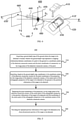
- FIG. 2 shows a flowchart of a target detection method 200 according to an embodiment of the present disclosure.
- the method 200 may be executed at a client device (for example, any one of the client devices 101 to 106 shown in FIG. 1 ), that is, an execution subject of each step of the method 200 may be any one of the client devices 101 to 106 shown in FIG. 1 .
- the method 200 may be executed at a server (for example, the server 120 shown in FIG. 1 ).
- the method 200 may be executed by a combination of a client device (for example, any one of the client devices 101 to 106) and a server (for example, the server 120). Taking the execution subject as the server 120 as an example, each step of the method 200 is described in detail below.
- the target detection method 200 includes step 210 to step 240.
- Step 210 a detection image of a target to be detected is acquired, wherein the detection image is an image taken by a detection monocular camera for the target to be detected.
- Step 220 a target detection model is acquired, wherein the target detection model is configured to extract position information of the target to be detected from the detection image, and the position information of the target to be detected comprises pixel coordinates of a projection, on an image plane of the detection monocular camera, of a center point of an orthographic projection of the target to be detected on a ground where the target to be detected is located.
- Step 230 the detection image is input into the target detection model to extract the position information of the target to be detected.
- Step 240 a three-dimensional position of the target to be detected is determined based on the position information of the target to be detected.
- the position information of the target to be detected may include pixel coordinates (using pixels as unit) of an image projection point, on the image plane of the detection monocular camera, of the center point of the orthographic projection of the target to be detected on the ground, and a length, a width, a height (for example, in meters) and a yaw angle of the target to be detected.
- the three-dimensional position of the target to be detected may include three-dimensional coordinates of the center point of the orthographic projection of the target to be detected on the ground in a coordinate system of the detection monocular camera.
- the three-dimensional coordinates of the center point of the orthographic projection of the target to be detected on the ground, the length, width, height, and yaw angle of the target to be detected may represent a three-dimensional bounding box of the target to be detected.
- the position information of the target to be detected may also include a two-dimensional bounding box of an image of the target to be detected.
- the target detection model may output the coordinate position of a ground center point of a target projected onto a camera, so as to acquire the three-dimensional position of the target. Since the image coordinates output by the target detection model do not depend on the external parameters between the detection monocular camera and the application scene, the model has a good generalization ability. Therefore, the detection method using this model can use the same target detection model to detect the target to be detected in a scene with different external parameters.
- FIG. 3 shows a flowchart of an example process of determining a three-dimensional position (step 240) of a target to be detected in the method 200 of FIG. 2 according to the embodiment of the present disclosure.
- step 240 of determining the three-dimensional position of the target to be detected based on the position information of the target to be detected further includes step 310 to step 360.
- Step 310 acquiring internal parameters of the detection monocular camera.
- Step 320 acquiring external parameters of the detection monocular camera, wherein the external parameters include parameters of a plane equation of the ground where the target to be detected is located in the coordinate system of the detection monocular camera.
- Step 330 determining, based on the internal parameters of the detection monocular camera and the position information of the target to be detected, a straight line which passes through an origin of the coordinate system of the detection monocular camera and the pixel coordinates of the projection, on the image plane of the detection monocular camera, of the center point of the orthographic projection of the target to be detected on the ground in the position information.
- the coordinates of the center point of the orthographic projection of the target to be detected on the ground in the coordinate system of the detection monocular camera are on the straight line.
- Step 340 determining, based on the straight line and the parameters of the plane equation of the ground, coordinates of an intersection point of the straight line and the ground in the coordinate system of the detection monocular camera as the coordinates of the center point of the orthographic projection of the target to be detected on the ground in the coordinate system of the detection monocular camera.
- Step 350 replacing the pixel coordinates of the projection, on the image plane of the detection monocular camera, of the center point of the orthographic projection in the position information of the target to be detected with the coordinates of the center point of the orthographic projection in the coordinate system of the detection monocular camera.
- Step 360 providing the replaced position information of the target to be detected as the three-dimensional position of the target to be detected.
- FIG. 4 shows a flowchart of an example operation 400 of determining a three-dimensional position of a target to be detected in the process of FIG. 3 according to the embodiment of the present disclosure.
- the example operation 400 includes a target 410 to be detected and a ground plane 420.
- An orthographic projection of the target 410 to be detected on the ground plane 420 is 410'.
- the orthographic projection 410' of the target to be detected has a center point 430.
- the example operation 400 also includes a detection monocular camera 440.
- a coordinate system 450 (X C -Y C -Z C ) of the monocular camera 440 is established by taking a focal point 470 of the detection monocular camera 440 as an origin, a direction perpendicular to the ground plane 420 as a Yc axis, a direction perpendicular to the paper surface as an Xc axis, and a direction perpendicular to the X C -Y C plane as a Z C axis.
- the detection monocular camera 440 has an image plane 460.
- center point 430 of the orthographic projection 410' of the target to be detected may be projected onto the image plane 460 through the focal point 470 to obtain an image projection point 430'.
- the position information of the target 410 to be detected may be predicted by a trained target detection model, which will not be repeated here.
- the position information of the target 410 to be detected includes the pixel coordinates of the image projection point 430', onto the image plane 460, of the center point 430 of the projection 410' of the target 410 to be detected on the ground 420.
- the center point 430 corresponding to the image projection point 430' is on the straight line 480.
- the center point 430 is the center point of the projection 410' of the target 410 to be detected on the ground 420, the center point 430 is located in the plane of the ground 420. Therefore, an intersection point of the straight line 480 and the ground 420 is the center point 430.
- the pixel coordinates of the image projection point 430' in the image plane 460 in the position information, which is extracted by the target detection model, of the target 410 to be detected are replaced with the coordinates of the center point 430 in the camera coordinate system 450.
- the replaced position information of the target 410 to be detected is provided as the three-dimensional position of the target 410 to be detected.
- the position information of the target to be detected is first predicted through a trained target detection model, and then according to the internal and external parameters of the camera known in advance, the three-dimensional coordinates of the center point are inferred based on the image projection coordinates of the center point.
- the external parameters of the camera are only used in the artificially controllable solution process, and the external parameters of the camera are not used in the uncontrollable model training. Therefore, the trained model can be combined with artificially controllable camera external parameters to detect targets in different scenes, which increases the application range of the detection method.
- FIG. 5 shows a flowchart of another example process of determining a three-dimensional position (step 240) of a target to be detected in the method 200 of FIG. 2 according to the embodiment of the present disclosure.
- step 240 of determining the three-dimensional position of the target to be detected based on the position information of the target to be detected further includes step 510 to step 540.
- Step 510 acquiring a ground depth map of the ground where the target to be detected is located, wherein the ground depth map represents a mapping relationship between coordinates of a point in the ground in the coordinate system of the detection monocular camera and the pixel coordinates of a projection, on the image plane of the detection monocular camera, of the point.
- Step 520 searching, based on the ground depth map, coordinates in the coordinate system of the detection monocular camera for the pixel coordinates of the projection, on the image plane of the detection monocular camera, of the center point of the orthographic projection of the target to be detected on the ground in the position information of the target to be detected.
- Step 530 replacing the pixel coordinates of the projection, on the image plane of the detection monocular camera, of the center point of the orthographic projection in the position information of the target to be detected with the coordinates of the center point of the orthographic projection in the coordinate system of the detection monocular camera.
- Step 540 providing the replaced position information of the target to be detected as the three-dimensional position of the target to be detected.
- FIG. 6 shows a flowchart of an example operation 600 of determining the three-dimensional position of the target to be detected in the process of FIG. 5 according to the embodiment of the present disclosure.
- the target 610 to be detected in FIG. 6 is the same as the target 410 to be detected in FIG. 4 .
- other similar reference numbers represent elements similar to those in FIG. 4 , and will not be repeated here.
- the example operation 600 includes a ground depth map 690.
- the ground depth map 690 represents the mapping relationship between the coordinates of the point in the ground 620 in the coordinate system 650 of the detection monocular camera and pixel coordinates of the image projection point, on the image plane coordinate system 660 of the detection monocular camera, of the point. That is to say, for a center point 630 of an orthographic projection 610' of the target 610 to be detected on the ground 620, the ground depth map 690 establishes a mapping relationship between coordinates of the center point 630 in the camera coordinate system 650 and pixel coordinates of an image projection point 630' in the image plane coordinate system 660.
- the pixel coordinates of the image projection point 630' can be obtained through a trained target detection model, which will not be repeated here.
- the coordinates of the center point 630 in the camera coordinate system 650 are found in the ground depth map 690.
- the pixel coordinates of the image projection point 630' in the image plane 660 in the position information, which is extracted by the target detection model, of the target 610 to be detected are replaced with the coordinates of the center point 630 in the camera coordinate system 650.
- the replaced position information of the target 610 to be detected is provided as the three-dimensional position of the target 610 to be detected.
- the three-dimensional coordinates of the center point of the target to be detected are found through the artificially controllable ground depth map, and the external parameters of the camera are not used in the uncontrollable model training. Therefore, the trained model can be combined with artificially controllable camera external parameters to detect targets in different scenes, which increases the application range of the detection method.
- the three-dimensional position of the target to be detected may be a three-dimensional bounding box of the target to be detected.
- FIG. 7 shows a schematic diagram of a structure 700 of a three-dimensional position of a target to be detected according to an embodiment of the present disclosure.
- the structure 700 of the three-dimensional position of the target to be detected may include three-dimensional coordinates of a center point 730 of the projection of the target 710 to be detected on the ground in a camera coordinate system 750.
- a length 760, a width 770, a height 780, and a yaw angle of the target 710 to be detected may also be included.
- the yaw angle may be, for example, an included angle between an axis 740 of the target to be detected and a coordinate axis X C .
- a three-dimensional bounding box 720 of the target 710 to be detected can be obtained from coordinates of the center point 730, the length 760, the width 770, the height 780, and the yaw angle to provide the three-dimensional position of the target 710 to be detected.
- FIG. 8 shows a flowchart of a training method 800 for a target detection model according to an embodiment of the present disclosure.
- the training method 800 for the target detection model may include step 810 to step 830.
- training data may be acquired, wherein the training data include a training image taken by a monocular camera for a target.
- the target detection model may detect position information of the target in the training image.
- the training data may further include, for example, a label corresponding to the training image, and the label may represent a true position of the target in the training image.
- a basic model may be constructed, wherein the basic model includes a multi-layer convolutional neural network.
- the multi-layer convolutional neural network is configured to extract position information of the target from the training image, and the position information of the target includes pixel coordinates of a projection, on an image plane of the monocular camera, of a center point of an orthographic projection of the target on a ground where the target is located.
- the basic model may include the multi-layer convolutional neural network.
- the multi-layer convolutional neural network may perform multiple convolutions on the training image input to the model and extract the position information of the target.
- the ground where the target is located is a plane
- the position information of the target extracted from the training image may include pixel coordinates of a projection point, onto the camera image plane, of a center point of an orthographic projection of the target on the ground plane.
- the pixel coordinates of the image projection point corresponding to the center point on the training image may change very little.
- the basic model can be trained using the training data to obtain a target detection model.
- the multi-layer convolutional neural network may learn to update a weight value of the neural network by returning the position information of the target.
- the prediction of the convolutional neural network on the position information of the target approximates a true value in the training data, thereby generating the target detection model.
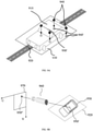
- FIG. 9A shows a schematic diagram of an orthographic center point of an orthographic projection of a target on a ground according to the embodiment of the present disclosure.
- FIG. 9A includes a target 910, a ground 920, an orthographic projection 930 of the target 910 onto the ground 920, a point 940 on the target 910, a projection point 940' of the point 940 onto the ground 920, and a center point 950' of the orthographic projection 930 of the target 910 onto the ground 920.
- the point 940 on the target 910 can be projected onto the ground 920 to obtain the projection point 940'.
- the orthographic projection 930 of the target 910 on the ground 920 can be obtained, and the center point 950' of the orthographic projection 930 can be obtained.
- FIG. 9B shows a top view of a projection, onto an image plane, of a center point of an orthographic projection of a target on a ground according to the embodiment of the present disclosure. Similar reference numbers in FIG. 9B represent elements similar to those in FIG. 9A , and will not be repeated here.
- the center point 950' of the orthographic projection 930 of the target 910 is projected onto an image plane 970 of a camera 960, and an image projection point 950" of the center point 950' is obtained.
- a label may be added to the image projection point 950" in the training image in the training data, and two-dimensional pixel coordinates of the image projection point 950" are used to replace three-dimensional coordinates of the projection point 950' as a regression parameter.
- the pixel coordinates of the projection, on the image plane, of the center point of the orthographic projection of the target on the ground have relatively small position changes and are used as the regression parameter. Therefore, the difficulty of parameter fitting in the training process of the target detection model can be reduced, and the training speed of the model can be improved.
- the three-dimensional coordinates of the center point of the orthographic projection of the target on the ground are not regressed, thereby reducing the dependence of the model on the external parameters of the camera and improving the generalization ability of the model.
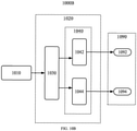
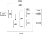
- FIGS. 10A-10C show schematic diagrams of a structure of a target detection model 1000A according to an embodiment of the present disclosure.
- the target detection model 1000A may include a training image 1010, a multi-layer convolutional neural network 1020, and position information 1090 of the target.
- the multi-layer convolutional neural network 1020 may include an image feature extraction layer 1030.
- the image feature extraction layer 1030 is configured to extract an image feature from the training image 1010.
- the multi-layer convolutional neural network 1020 may further include a target parameter extraction layer 1040.
- the target parameter extraction layer 1040 is configured to extract the position information 1090 of the target based on the image feature.
- the target parameter extraction layer 1040 may include a three-dimensional information detection layer 1042.
- the three-dimensional information detection layer 1042 is configured to detect three-dimensional position information 1092 of the target based on the image feature.
- the position information 1090 of the target may include the three-dimensional position information 1092 of the target.
- the three-dimensional position information 1092 of the target may include the length, width, height, and yaw angle of the target in the coordinate system of the monocular camera.
- the image feature extraction layer 1030 may be any image feature extraction network in related art, such as a visual geometric group network (VGG), a residual network (ResNet), and a mobile neural network (MobileNet).
- VCG visual geometric group network
- ResNet residual network
- MobileNet mobile neural network
- the three-dimensional information detection layer 1042 may be any network based on three-dimensional information of a monocular vision detection target in related art, such as a first-order neural network YOLO (You Only Look Once), and a feature-pyramid-based SSD (Single Shot MultiBox Detector) network, and an AnchorBased network.
- a monocular vision detection target in related art, such as a first-order neural network YOLO (You Only Look Once), and a feature-pyramid-based SSD (Single Shot MultiBox Detector) network, and an AnchorBased network.
- the multi-layer convolutional neural network 1020 further includes the image feature extraction layer 1030 and the target parameter extraction layer 1040.
- the image feature extraction layer 1030 may extract the image feature using a mature two-dimensional target feature extraction technique in related art.
- the image feature is input to the target parameter extraction layer 1040 to extract target position information including, for example, a pixel coordinates of an image projection point of the center point of the orthographic projection of a target on the ground.
- the target parameter extraction layer 1040 extracts two-dimensional pixel points as regression parameters, thus avoiding the problem of difficult collection and calibration of the training set that extracts three-dimensional coordinates as regression parameters.
- FIG. 10B shows a schematic diagram of a structure of a target detection model 1000B according to another embodiment of the present disclosure. Similar reference numbers in FIG. 10B represent elements similar to those in FIG. 10A , and will not be repeated here.
- the target parameter extraction layer 1040 further includes a two-dimensional information detection layer 1044.
- the two-dimensional information detection layer 1044 is configured to detect two-dimensional position information 1094 of a target image, projected on the image plane of the monocular camera, of a target in the image plane coordinate system of the monocular camera, based on the image feature.
- the position information 1090 of the target may further include the two-dimensional position information 1094 of the target.
- the two-dimensional position information 1094 which is detected by the two-dimensional information detection layer 1044, of the target image on the image plane may include a height and a width of the target image in the image plane coordinate system, the pixel coordinates of a center point of the target image, a confidence level and a score; in addition, the height and width of the target image in the image plane coordinate system and the pixel coordinates of the center point of the target image may represent a two-dimensional bounding box of the target image.
- the confidence level may represent the proximity between the two-dimensional bounding box and a real two-dimensional bounding box in the training data.
- the score may represent a degree of overlap between the two-dimensional bounding box and the real two-dimensional bounding box.
- the two-dimensional position information of the target in the training image is added to the position information of the target, thereby enriching the information that the target detection model can predict.
- the two-dimensional position information of the bounding box and the geometric constraints of the target can be used to improve the accuracy of predicting the three-dimensional position of the target.
- FIG. 10C shows a schematic diagram of a structure of a target detection model 1000C according to another embodiment of the present disclosure. Similar reference numbers in FIG. 10C represent elements similar to those in FIGS. 10A and 10B , and will not be repeated here.
- the multi-layer convolutional neural network 1020 further includes a region candidate network layer 1050.
- the region candidate network layer 1050 is configured to detect an image candidate region of the target based on the image feature.
- the multi-layer convolutional neural network 1020 further includes a candidate region pooling layer 1060.
- the candidate region pooling layer 1060 is configured to extract and input a feature of the image candidate region to the target parameter extraction layer 1040 based on the image feature and the image candidate region.
- the region candidate network layer 1050 may make a preliminary position estimation on a region containing the target image and may be trained as a single first-order model, so that the target detection model 1000C may be a second-order detection model.
- the region candidate network layer 1050 may be any network that extracts a target candidate region in related art, such as RPN networks (Region Proposal Networks).
- RPN networks Regular Proposal Networks
- the candidate region pooling layer 1060 may be any network in the related art that extracts a candidate region feature according to the target candidate region and the image feature, such as an ROI (Region Of Interest) Pooling network.
- ROI Region Of Interest
- the image candidate region output by the region candidate network layer 1050 and the image feature extracted by the image feature extraction layer 1030 can be input to the candidate region pooling layer 1060 to obtain the image feature of the candidate region.
- the candidate network layer 450 and the candidate region pooling layer 1060 limit the detection of the target to the region that may contain the target image, so that a subsequent detection operation only needs to be performed in the candidate region, speeding up the detection of the three-dimensional position information and/or the two-dimensional position information of the target.
- FIG. 11 shows a flowchart of an example process of training a basic model (step 830) in the method 800 of FIG. 8 according to an embodiment of the present disclosure.
- step 830 of training the basic model using the training data to obtain a target detection model further includes step 1110 to step 1130.
- Step 1110 the training data are input to the basic model.
- Step 1120 an error is calculated between the position information of the target extracted by the multi-layer convolutional neural network and a corresponding true value in the data according to an error function of the basic model.
- Step 1130 back-propagation training is performed on the multi-layer convolutional neural network according to the error to obtain the target detection model.
- training data can be input and the weight parameters of the multi-layer convolutional neural network can be initialized. Then data is input into the model in batches for forward propagation. Next, an error between the position information of the target predicted by the model and the true value identified in the training data is calculated. Further, an error gradient is propagated back and the weight value is updated. Finally, the iteration is repeated to bring the error gradient to zero.
- the error function of the model can be designed as the Euclidean distance between the predicted position information of the target of the model and the true value.
- the predicted output of the target detection model can be made close to the true value.
- the parameters of the convolutional neural network used for regression in the training process are the target position information including image projection coordinates of the center point of the orthographic projection of the target, the training convergence speed is fast while increasing the generalization ability of the target detection model.
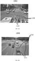
- FIGS. 12A-12B show schematic diagrams of detecting an example target by the target detection method according to the embodiment of the present disclosure.
- FIG. 12A a scene 1200A is detected using a trained target detection model.
- a detection result is shown in FIG. 12A , and a three-dimensional position of a target 1210 to be detected includes a three-dimensional bounding box 1220.
- FIG. 12B a scene 1200B is detected using the same target detection model.
- a detection result is shown in FIG. 12B , and a three-dimensional position of a target 1212 to be detected includes a three-dimensional bounding box 1222.
- the three-dimensional position of the target can still be detected in the case of different scenes and external parameters.
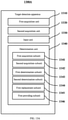
- FIGS. 13A-13B show block diagrams of a target detection apparatus 1300A according to an embodiment of the present disclosure.
- the target detection apparatus 1300A includes: a first acquisition unit 1310 configured to acquire a detection image of a target to be detected, wherein the detection image is an image taken by a detection monocular camera for the target to be detected; a second acquisition unit 1320 configured to acquire a target detection model, wherein the target detection model is configured to extract position information of the target to be detected from the detection image, and the position information of the target to be detected includes pixel coordinates of a projection, on an image plane of the detection monocular camera, of a center point of an orthographic projection of the target to be detected on a ground where the target to be detected is located; an input unit 1330 configured to input the detection image into the target detection model to extract the position information of the target to be detected; and a determination unit 1340 configured to determine a three-dimensional position of the target to be detected based on the position information of the target to be detected.
- the determination unit 1340 may include:
- FIG. 13B shows a block diagram of a target detection apparatus 1300B according to another embodiment of the present disclosure. Similar reference numbers in FIG. 13B represent elements similar to those in FIG. 13A , and will not be repeated here.
- the determination unit 1350 may include:
- FIG. 14 shows a block diagram of a training apparatus 1400 for a target detection model according to an embodiment of the present disclosure.
- the training apparatus 1400 for the target detection model includes: a third acquisition unit 1410 configured to acquire training data, wherein the training data include a training image taken by a monocular camera for a target; a construction unit 1420 configured to construct a basic model, wherein the basic model includes a multi-layer convolutional neural network configured to extract position information of the target from the training image, and the position information of the target includes pixel coordinates of a projection, on an image plane of the monocular camera, of a center point of an orthographic projection of the target on a ground where the target is located; and a training unit 1430 configured to train the basic model using the training data to obtain a target detection model.
- the units and subunits of the apparatuses 1300A and 1300B shown in FIGS. 13A-13B may correspond to the steps in the method 200 described with reference to FIGS. 2 to 7 . Therefore, the operations, features and advantages described above regarding the method 200 are also applicable to the apparatuses 1300A and 1300B and the units and subunits included therein, and will not be repeated for the sake of brevity.
- the units and subunits of the apparatus 1400 shown in FIG. 14 may correspond to the steps in the method 800 described with reference to FIGS. 8 to 11 . Therefore, the operations, features and advantages described above regarding the method 800 are also applicable to the apparatus 1400 and the units and subunits included therein, and will not be repeated for the sake of brevity.
- a specific unit performing an action discussed herein includes the specific unit itself performing the action, or alternatively the specific unit calling or otherwise accessing another component or unit that performs the action (or performing the action in conjunction with the specific unit) in an another manner. Therefore, the specific unit performing the action may include the specific unit itself performing the action and/or another unit that is called or accessed in another manner by the specific unit to perform the action.
- Various techniques may be described herein in the general context of software hardware elements or program modules.
- the units and subunits described above may be implemented in hardware or in hardware combined with software and/or firmware.
- these units and subunits may be implemented as computer program codes/instructions, and the computer program codes/instructions are configured to be executed in one or more processors and stored in a computer-readable storage medium.
- these modules can be implemented as hardware logic/circuitry.
- one or more of the units and sub-units may be implemented together in a system on chip (SoC).
- SoC system on chip
- the SoC may include an integrated circuit chip (which includes a processor (for example, a central processing unit (CPU), a microcontroller, a microprocessor, a digital signal processor (DSP)), a memory, one or more communication interfaces, and/or one or more components in other circuits), and can optionally execute the received program code and/or include embedded firmware to perform functions.
- a processor for example, a central processing unit (CPU), a microcontroller, a microprocessor, a digital signal processor (DSP)
- DSP digital signal processor
- an electronic device including: a memory, a processor, and a computer program stored on the memory, wherein the processor is configured to execute the computer program to implement the steps of the above method of the present disclosure.
- a non-transitory computer-readable storage medium with a computer program stored thereon, wherein the computer program, when executed by a processor, implements the steps of the above method in the present disclosure.
- a computer program product including a computer program, wherein the computer program, when executed by a processor, implements the steps of the above method in the present disclosure.
- FIG. 15 shows a structural block diagram of an exemplary electronic device 1500 that can be used to implement an embodiment of the present disclosure.
- Electronic devices are intended to mean various forms of digital electronic devices, such as laptop computers, desktop computers, workstations, personal digital assistants, servers, blade servers, mainframe computers, and other suitable computers. Electronic devices may also represent various forms of mobile devices, such as personal digital processing devices, cellular phones, smart phones, wearable devices, and other similar computing devices.
- the components shown herein, their connections and relationships, and their functions are merely examples, and are not intended to limit the implementation of the present disclosure described and/or required herein.
- the device 1500 includes a computing unit 1501 that can perform various appropriate actions and processes according to a computer program stored in a read-only memory (ROM) 1502 or a computer program loaded into a random access memory (RAM) 1503 from a storage unit 1508.
- ROM read-only memory
- RAM random access memory
- various programs and data required for the operation of the device 1500 can also be stored.
- the computing unit 1501, the ROM 1502 and the RAM 1503 are connected to each other through a bus 1504.
- An input/output (I/O) interface 1505 is also connected to the bus 1504.
- a plurality of components in the device 1500 are connected to the I/O interface 1505, including: an input unit 1506, an output unit 1507, a storage unit 1508, and a communication unit 1509.
- the input unit 1506 may be any type of device capable of inputting information to the device 1500.
- the input unit 1506 can receive inputted number or character information, and generate a key signal input related to user settings and/or function control of the electronic device.
- the input unit 1506 may include, but is not limited to, a mouse, a keyboard, a touch screen, a trackpad, a trackball, a joystick, a microphone, and/or a remote control.
- the output unit 1507 may be any type of device capable of presenting information, and may include, but is not limited to, a display, a speaker, a video/audio output terminal, a vibrator, and/or a printer.
- the storage unit 1508 may include, but is not limited to, a magnetic disk and an optical disk.
- the communication unit 1509 allows the device 1500 to exchange information/data with other devices through a computer network such as the Internet and/or various telecommunication networks.
- the communication unit 1509 may include, but is not limited to, a modem, a network card, an infrared communication device, a wireless communication transceiver, and/or a chipset, such as a Bluetooth TM device, a 1302.11 device, a WiFi device, a WiMax device, a cellular communication device, and/or the like.
- the computing unit 1501 may be various general-purpose and/or special-purpose processing components with processing and computing capabilities. Some examples of the computing unit 1501 include but are not limited to central processing units (CPUs), graphics processing units (GPUs), various dedicated artificial intelligence (AI) computing chips, various computing units running machine learning model algorithms, digital signal processors (DSPs), and any appropriate processors, controllers, microcontrollers, etc.
- the computing unit 1501 executes the various methods and processes described above, for example, one or both of the method 200 and the method 600. For example, in some embodiments, one or both of the method 200 and the method 600 may be implemented as a computer software program, which is tangibly contained in a machine-readable medium, such as the storage unit 1508.
- part or all of the computer program may be loaded and/or installed on the device 1500 via the ROM 1502 and/or the communication unit 1509.
- the computer program When the computer program is loaded into the RAM 1503 and executed by the computing unit 1501, one or more steps in one or both of the method 200 and the method 800 described above may be executed.
- the computing unit 1501 may be configured to perform one or both of the method 200 and the method 800 in any other suitable manner (for example, by means of firmware).
- Various implementations of the systems and techniques described herein above can be implemented in digital electronic circuit systems, integrated circuit systems, field programmable gate arrays (FPGAs), application specific integrated circuits (ASICs), application specific standard products (ASSPs), systems on chip (SOC), complex programmable logic devices (CPLD), computer hardware, firmware, software, and/or combinations thereof.
- FPGAs field programmable gate arrays
- ASICs application specific integrated circuits
- ASSPs application specific standard products
- SOC systems on chip
- CPLD complex programmable logic devices
- computer hardware firmware, software, and/or combinations thereof.
- the programmable processor may be a special-purpose or general-purpose programmable processor, may receive data and instructions from a storage system, at least one input device, and at least one output device, and transmit the data and instructions to the storage system, the at least one input device, and the at least one output device.
- Program codes for implementing the methods of the present disclosure can be written in any combination of one or more programming languages. These program codes may be provided to the processor or controller of a general-purpose computer, special-purpose computer, or other programmable data processing device, so that the program codes, when executed by the processor or the controller, cause the functions/operations specified in the flowchart and/or block diagram to be implemented.
- the program codes can be executed completely on a machine, partially on the machine, partially on the machine as an independent software package and partially on a remote machine, or completely on the remote machine or a server.
- a machine-readable medium may be a tangible medium, which may contain or store a program for use by an instruction execution system, apparatus or device, or use in combination with the instruction execution system, apparatus or device.
- the machine-readable medium may be a machine-readable signal medium or a machine-readable storage medium.
- the machine-readable medium may include, but is not limited to, an electronic, magnetic, optical, electromagnetic, infrared, or semiconductor system, apparatus or device, or any suitable combination thereof.
- machine-readable storage medium More specific examples of the machine-readable storage medium would include an electrical connection based on one or more wires, a portable computer disk, a hard disk, a random access memory (RAM), a read-only memory (ROM), an erasable programmable read-only memory (EPROM or flash memory), an optical fiber, a portable compact disk read-only memory (CD-ROM), an optical storage device, a magnetic storage device, or any suitable combination thereof.
- RAM random access memory
- ROM read-only memory
- EPROM or flash memory erasable programmable read-only memory
- CD-ROM portable compact disk read-only memory
- magnetic storage device or any suitable combination thereof.
- the systems and techniques described here can be implemented on a computer that has: a display device for displaying information to the user (for example, a CRT (cathode ray tube) or LCD (liquid crystal display) monitor)); and a keyboard and a pointing device (for example, a mouse or a trackball) through which the user can provide an input to the computer.
- a display device for displaying information to the user
- a keyboard and a pointing device for example, a mouse or a trackball
- Other types of devices can also be used to provide interaction with the user; for example, the feedback provided to the user can be any form of sensory feedback (for example, visual feedback, auditory feedback, or tactile feedback); and can receive the input from the user in any form (including acoustic input, voice input, or tactile input).
- the systems and techniques described here can be implemented in a computing system that includes a back-end component (for example, as a data server), or a computing system that includes a middleware component (for example, an application server), or a computing system that includes a front-end component (for example, a user computer with a graphical user interface or web browser through which the user can interact with the implementation of the systems and techniques described here), or a computing system that includes any combination of such back-end component, middleware component or front-end component.
- the components of a system can be connected to each other through any form or medium of digital data communication (for example, a communication network). Examples of the communication network include: a local area network (LAN), a wide area network (WAN) and the Internet.
- the computer system may include a client and a server.
- the client and server are generally far away from each other and usually interact through a communication network.
- a relationship between the client and the server is generated by computer programs that run on the corresponding computers and have a client-server relationship with each other.
- a roadside device including the above-mentioned electronic device 1500.
- the roadside device may also include a communication component, etc.
- the electronic device 1500 may be integrated with the communication component, or may be provided separately.
- the electronic device 1500 may acquire data of a sensing device (such as a roadside camera), such as a picture and a video, thereby performing image video processing and data computation.
- a cloud control platform including the above-mentioned electronic device 1500.
- the cloud control platform performs processing in the cloud, and the electronic device 1500 included in the cloud control platform may acquire data of a sensing device (such as a roadside camera), such as a picture and a video, thereby performing image video processing and data computation.
- the cloud control platform can also be called a vehicle-road collaborative management platform, an edge computing platform, a cloud computing platform, a central system, a cloud server, etc.
Landscapes
- Engineering & Computer Science (AREA)
- Theoretical Computer Science (AREA)
- Physics & Mathematics (AREA)
- General Physics & Mathematics (AREA)
- Multimedia (AREA)
- Computer Vision & Pattern Recognition (AREA)
- Evolutionary Computation (AREA)
- Artificial Intelligence (AREA)
- General Health & Medical Sciences (AREA)
- Health & Medical Sciences (AREA)
- Software Systems (AREA)
- Computing Systems (AREA)
- Molecular Biology (AREA)
- Biomedical Technology (AREA)
- Life Sciences & Earth Sciences (AREA)
- Databases & Information Systems (AREA)
- Medical Informatics (AREA)
- Biophysics (AREA)
- Computational Linguistics (AREA)
- Data Mining & Analysis (AREA)
- General Engineering & Computer Science (AREA)
- Mathematical Physics (AREA)
- Biodiversity & Conservation Biology (AREA)
- Image Analysis (AREA)
- Radar Systems Or Details Thereof (AREA)
- Geophysics And Detection Of Objects (AREA)
Applications Claiming Priority (1)
| Application Number | Priority Date | Filing Date | Title |
|---|---|---|---|
| CN202011564385.6A CN112668460A (zh) | 2020-12-25 | 2020-12-25 | 目标检测方法、电子设备、路侧设备和云控平台 |
Publications (2)
| Publication Number | Publication Date |
|---|---|
| EP3961579A2 true EP3961579A2 (de) | 2022-03-02 |
| EP3961579A3 EP3961579A3 (de) | 2022-06-29 |
Family
ID=75409319
Family Applications (1)
| Application Number | Title | Priority Date | Filing Date |
|---|---|---|---|
| EP21217200.1A Withdrawn EP3961579A3 (de) | 2020-12-25 | 2021-12-22 | Zieldetektionsverfahren, vorrichtung, medium und computerprogrammprodukt |
Country Status (5)
| Country | Link |
|---|---|
| US (1) | US11721042B2 (de) |
| EP (1) | EP3961579A3 (de) |
| JP (1) | JP2022043216A (de) |
| KR (1) | KR20220004607A (de) |
| CN (1) | CN112668460A (de) |
Cited By (3)
| Publication number | Priority date | Publication date | Assignee | Title |
|---|---|---|---|---|
| CN114612558A (zh) * | 2022-03-10 | 2022-06-10 | 西安交通大学 | 一种基于单目相机检测的叉车托盘空间定位方法及系统 |
| CN114782547A (zh) * | 2022-04-13 | 2022-07-22 | 北京爱笔科技有限公司 | 一种三维坐标确定方法及装置 |
| EP4167189A1 (de) * | 2021-12-27 | 2023-04-19 | Beijing Baidu Netcom Science Technology Co., Ltd. | Anzeigeverfahren, anzeigevorrichtung, elektronische vorrichtung und speichermedium |
Families Citing this family (41)
| Publication number | Priority date | Publication date | Assignee | Title |
|---|---|---|---|---|
| CN113344200B (zh) * | 2021-06-17 | 2024-05-28 | 阿波罗智联(北京)科技有限公司 | 用于训练可分离卷积网络的方法、路侧设备及云控平台 |
| CN113580134B (zh) * | 2021-08-03 | 2022-11-04 | 亿咖通(湖北)技术有限公司 | 视觉定位方法、设备、机器人、存储介质及程序产品 |
| WO2023201723A1 (zh) * | 2022-04-22 | 2023-10-26 | 华为技术有限公司 | 目标检测模型的训练方法、目标检测方法及装置 |
| CN114723827A (zh) * | 2022-04-28 | 2022-07-08 | 哈尔滨理工大学 | 一种基于深度学习的抓取机器人目标定位系统 |
| CN115019226A (zh) * | 2022-05-13 | 2022-09-06 | 云南农业大学 | 一种基于改进型YoloV4模型的茶叶采摘识别方法 |
| CN114925295B (zh) * | 2022-06-08 | 2026-02-27 | 北京百度网讯科技有限公司 | 确定兴趣点的引导点的方法、相关装置及计算机程序产品 |
| CN115079229B (zh) * | 2022-06-15 | 2025-02-07 | 中国电子科技集团公司第二十八研究所 | 一种基于单目相机的无人机对地目标定位方法 |
| CN115009321B (zh) * | 2022-06-27 | 2024-07-12 | 南京理工大学 | 基于改进YoloX-s的密贴检查器故障检测方法 |
| CN117376577A (zh) * | 2022-07-01 | 2024-01-09 | 中国电信股份有限公司 | 视觉图像数据处理方法、装置、电子设备及介质 |
| CN115082886B (zh) * | 2022-07-04 | 2023-09-29 | 小米汽车科技有限公司 | 目标检测的方法、装置、存储介质、芯片及车辆 |
| CN117351451A (zh) * | 2022-08-17 | 2024-01-05 | 杭州涿溪脑与智能研究所 | 一种优化地平面先验的单目3d目标检测方法及装置 |
| CN115346194B (zh) * | 2022-08-25 | 2026-03-13 | 北京精英路通科技有限公司 | 一种三维检测方法、装置、电子设备及存储介质 |
| CN115184378B (zh) * | 2022-09-15 | 2024-03-29 | 北京思莫特科技有限公司 | 一种基于移动设备的混凝土结构病害检测系统及方法 |
| CN115393423A (zh) * | 2022-09-19 | 2022-11-25 | 北京京东尚科信息技术有限公司 | 目标检测方法和装置 |
| CN115578470B (zh) * | 2022-09-22 | 2024-06-07 | 虹软科技股份有限公司 | 一种单目视觉定位方法、装置、存储介质和电子设备 |
| CN115546130A (zh) * | 2022-09-26 | 2022-12-30 | 智道网联科技(北京)有限公司 | 用于数字孪生的身高测量方法、装置及电子设备 |
| CN115578336A (zh) * | 2022-09-29 | 2023-01-06 | 北京百度网讯科技有限公司 | 一种目标检测方法、装置、电子设备及存储介质 |
| CN115351713B (zh) * | 2022-10-19 | 2023-06-02 | 武汉艾极涂科技有限公司 | 一种基于图像识别的喷砂方法、装置、设备及存储介质 |
| CN115984766B (zh) * | 2022-12-08 | 2025-07-15 | 中国矿业大学 | 一种煤矿井下快速单目视觉三维目标检测方法 |
| CN115830140B (zh) * | 2022-12-12 | 2024-08-20 | 中国人民解放军海军工程大学 | 一种海上近程光电监控方法、系统、介质、设备及终端 |
| CN116129422B (zh) * | 2022-12-15 | 2026-01-16 | 广州赛特智能科技有限公司 | 单目3d目标检测方法、装置、电子设备和存储介质 |
| CN115661158B (zh) * | 2022-12-28 | 2023-04-25 | 歌尔光学科技有限公司 | 光机镜头组件的检测方法、装置、电子设备及存储介质 |
| CN116092002B (zh) * | 2023-01-03 | 2026-04-14 | 北京辰安科技股份有限公司 | 人群密度检测方法、装置、电子设备及介质 |
| CN116704019B (zh) * | 2023-01-05 | 2024-08-16 | 中国矿业大学(北京) | 一种基于锚杆网络的钻锚机器人单目视觉定位方法 |
| CN116012786A (zh) * | 2023-01-09 | 2023-04-25 | 广州市高速公路有限公司 | 一种2d和3d结合的区域入侵监测方法、系统与存储介质 |
| CN115984670B (zh) * | 2023-01-12 | 2025-11-07 | 阿波罗智联(北京)科技有限公司 | 模型训练和障碍物距离确定方法、装置、电子设备和介质 |
| CN116152783B (zh) * | 2023-04-18 | 2023-08-04 | 安徽蔚来智驾科技有限公司 | 目标元素标注数据的获取方法、计算机设备及存储介质 |
| CN116543381B (zh) * | 2023-04-24 | 2026-02-03 | 爱芯元智半导体股份有限公司 | 单目三维目标检测后处理方法、装置和电子设备 |
| CN116681882B (zh) * | 2023-05-17 | 2025-12-02 | 深圳海星智驾科技有限公司 | 一种单目视觉三维物体检测方法、装置、域控制器及介质 |
| CN116844151A (zh) * | 2023-05-31 | 2023-10-03 | 武汉轩辕智驾科技有限公司 | 单目3d目标检测的方法、系统、电子设备和存储介质 |
| CN116681778B (zh) * | 2023-06-06 | 2024-01-09 | 固安信通信号技术股份有限公司 | 一种基于单目相机的距离测量方法 |
| CN116704495B (zh) * | 2023-06-14 | 2025-10-31 | 华东师范大学 | 基于目标表面点与地面映射的单目3d检测模型的构建方法 |
| CN117115789A (zh) * | 2023-06-14 | 2023-11-24 | 中国人民解放军火箭军工程大学 | 一种时敏目标检测网络及时敏目标消隐方法 |
| CN116823232B (zh) * | 2023-08-28 | 2023-12-01 | 中交公路长大桥建设国家工程研究中心有限公司 | 一种桥梁表观病害巡检方法、巡检系统以及巡检装置 |
| CN117274575B (zh) * | 2023-09-28 | 2025-01-14 | 北京百度网讯科技有限公司 | 目标检测模型的训练方法、目标检测方法、装置和设备 |
| CN117132767B (zh) * | 2023-10-23 | 2024-03-19 | 中国铁塔股份有限公司湖北省分公司 | 一种小目标检测方法、装置、设备及可读存储介质 |
| CN117788844A (zh) * | 2023-12-22 | 2024-03-29 | 蔚来汽车科技(安徽)有限公司 | 目标检测方法、智能设备及存储介质 |
| CN117611592B (zh) * | 2024-01-24 | 2024-04-05 | 长沙隼眼软件科技有限公司 | 一种异物检测方法、装置、电子设备以及存储介质 |
| KR102824854B1 (ko) * | 2024-08-13 | 2025-06-25 | 주식회사 실리콘큐브 | 단일 카메라를 이용한 뎁스 맵 기반 공간 위치 판별 방법 및 그 시스템 |
| CN119478980B (zh) * | 2024-11-08 | 2025-05-09 | 北京爱学思技术有限公司 | 一种基于神经网络的作业试卷检测切分方法 |
| CN120339806A (zh) * | 2025-06-23 | 2025-07-18 | 成都正扬博创电子技术有限公司 | 一种人影作业目标云层识别方法、系统、设备及介质 |
Family Cites Families (14)
| Publication number | Priority date | Publication date | Assignee | Title |
|---|---|---|---|---|
| EP2722646B1 (de) * | 2011-06-14 | 2021-06-09 | Nissan Motor Co., Ltd. | Abstandsmessvorrichtung und vorrichtung zur erzeugung einer umgebungskarte |
| JP6547785B2 (ja) * | 2016-07-29 | 2019-07-24 | 株式会社デンソー | 物標検出装置 |
| JP6602743B2 (ja) * | 2016-12-08 | 2019-11-06 | 株式会社ソニー・インタラクティブエンタテインメント | 情報処理装置および情報処理方法 |
| CN110494863B (zh) * | 2018-03-15 | 2024-02-09 | 辉达公司 | 确定自主车辆的可驾驶自由空间 |
| CN109345510A (zh) * | 2018-09-07 | 2019-02-15 | 百度在线网络技术(北京)有限公司 | 物体检测方法、装置、设备、存储介质及车辆 |
| US11105924B2 (en) * | 2018-10-04 | 2021-08-31 | Waymo Llc | Object localization using machine learning |
| US11093761B2 (en) * | 2019-03-06 | 2021-08-17 | GM Global Technology Operations LLC | Lane position sensing and tracking in a vehicle |
| CN110032949B (zh) * | 2019-03-22 | 2021-09-28 | 北京理工大学 | 一种基于轻量化卷积神经网络的目标检测与定位方法 |
| CN110070025B (zh) | 2019-04-17 | 2023-03-31 | 上海交通大学 | 基于单目图像的三维目标检测系统及方法 |
| CN110427917B (zh) * | 2019-08-14 | 2022-03-22 | 北京百度网讯科技有限公司 | 用于检测关键点的方法和装置 |
| CN111126269B (zh) | 2019-12-24 | 2022-09-30 | 京东科技控股股份有限公司 | 三维目标检测方法、装置以及存储介质 |
| CN111310574B (zh) | 2020-01-17 | 2022-10-14 | 清华大学 | 一种车载视觉实时多目标多任务联合感知方法和装置 |
| CN111814548B (zh) * | 2020-06-03 | 2022-12-09 | 中铁第四勘察设计院集团有限公司 | 一种异常行为检测方法和装置 |
| CN112101209B (zh) * | 2020-09-15 | 2024-04-09 | 阿波罗智联(北京)科技有限公司 | 用于路侧计算设备的确定世界坐标点云的方法和装置 |
-
2020
- 2020-12-25 CN CN202011564385.6A patent/CN112668460A/zh active Pending
-
2021
- 2021-12-22 KR KR1020210185137A patent/KR20220004607A/ko not_active Ceased
- 2021-12-22 EP EP21217200.1A patent/EP3961579A3/de not_active Withdrawn
- 2021-12-23 US US17/561,242 patent/US11721042B2/en active Active
- 2021-12-24 JP JP2021210257A patent/JP2022043216A/ja active Pending
Cited By (3)
| Publication number | Priority date | Publication date | Assignee | Title |
|---|---|---|---|---|
| EP4167189A1 (de) * | 2021-12-27 | 2023-04-19 | Beijing Baidu Netcom Science Technology Co., Ltd. | Anzeigeverfahren, anzeigevorrichtung, elektronische vorrichtung und speichermedium |
| CN114612558A (zh) * | 2022-03-10 | 2022-06-10 | 西安交通大学 | 一种基于单目相机检测的叉车托盘空间定位方法及系统 |
| CN114782547A (zh) * | 2022-04-13 | 2022-07-22 | 北京爱笔科技有限公司 | 一种三维坐标确定方法及装置 |
Also Published As
| Publication number | Publication date |
|---|---|
| KR20220004607A (ko) | 2022-01-11 |
| JP2022043216A (ja) | 2022-03-15 |
| CN112668460A (zh) | 2021-04-16 |
| EP3961579A3 (de) | 2022-06-29 |
| US20220114759A1 (en) | 2022-04-14 |
| US11721042B2 (en) | 2023-08-08 |
Similar Documents
| Publication | Publication Date | Title |
|---|---|---|
| US11721042B2 (en) | Target detection method, electronic device and medium | |
| CN115147558B (zh) | 三维重建模型的训练方法、三维重建方法及装置 | |
| CN115578433B (zh) | 图像处理方法、装置、电子设备及存储介质 | |
| CN113724388B (zh) | 高精地图的生成方法、装置、设备以及存储介质 | |
| CN115841552B (zh) | 高精地图生成方法及装置、电子设备和介质 | |
| CN115953414A (zh) | 基于语义分割的低矮障碍物检测方法和自动驾驶车辆 | |
| CN114898387A (zh) | 表格图像处理方法和装置 | |
| CN115511779B (zh) | 图像检测方法、装置、电子设备和存储介质 | |
| CN114723949A (zh) | 三维场景分割方法和用于训练分割模型的方法 | |
| CN113139542B (zh) | 目标检测方法、装置、设备和计算机可读存储介质 | |
| CN114896445B (zh) | 兴趣点位置的确定方法及装置、电子设备和存储介质 | |
| US20240070516A1 (en) | Machine learning context based confidence calibration | |
| US20220227374A1 (en) | Data processing | |
| CN114926656A (zh) | 对象识别方法、装置、设备及介质 | |
| CN112987707B (zh) | 一种车辆的自动驾驶控制方法及装置 | |
| CN112507951A (zh) | 指示灯识别方法、装置、设备、路侧设备和云控平台 | |
| CN115578432B (zh) | 图像处理方法、装置、电子设备及存储介质 | |
| CN115797660B (zh) | 图像检测方法、装置、电子设备和存储介质 | |
| CN115345981B (zh) | 图像处理方法、装置、电子设备和存储介质 | |
| CN114299192B (zh) | 定位建图的方法、装置、设备和介质 | |
| CN115797455A (zh) | 目标检测方法、装置、电子设备和存储介质 | |
| CN115131562A (zh) | 三维场景分割方法、模型训练方法、装置和电子设备 | |
| CN115953354A (zh) | 高精地图中用于检测点云数据偏差的方法、设备和介质 | |
| CN111968030B (zh) | 信息生成方法、装置、电子设备和计算机可读介质 | |
| CN116311271A (zh) | 文本图像的处理方法及装置 |
Legal Events
| Date | Code | Title | Description |
|---|---|---|---|
| PUAI | Public reference made under article 153(3) epc to a published international application that has entered the european phase |
Free format text: ORIGINAL CODE: 0009012 |
|
| STAA | Information on the status of an ep patent application or granted ep patent |
Free format text: STATUS: REQUEST FOR EXAMINATION WAS MADE |
|
| 17P | Request for examination filed |
Effective date: 20211222 |
|
| AK | Designated contracting states |
Kind code of ref document: A2 Designated state(s): AL AT BE BG CH CY CZ DE DK EE ES FI FR GB GR HR HU IE IS IT LI LT LU LV MC MK MT NL NO PL PT RO RS SE SI SK SM TR |
|
| PUAL | Search report despatched |
Free format text: ORIGINAL CODE: 0009013 |
|
| AK | Designated contracting states |
Kind code of ref document: A3 Designated state(s): AL AT BE BG CH CY CZ DE DK EE ES FI FR GB GR HR HU IE IS IT LI LT LU LV MC MK MT NL NO PL PT RO RS SE SI SK SM TR |
|
| RIC1 | Information provided on ipc code assigned before grant |
Ipc: G06V 30/18 20220101ALI20220523BHEP Ipc: G06V 20/54 20220101AFI20220523BHEP |
|
| STAA | Information on the status of an ep patent application or granted ep patent |
Free format text: STATUS: EXAMINATION IS IN PROGRESS |
|
| 17Q | First examination report despatched |
Effective date: 20230327 |
|
| STAA | Information on the status of an ep patent application or granted ep patent |
Free format text: STATUS: THE APPLICATION IS DEEMED TO BE WITHDRAWN |
|
| 18D | Application deemed to be withdrawn |
Effective date: 20231007 |