EP3961248A1 - Terminal - Google Patents
Terminal Download PDFInfo
- Publication number
- EP3961248A1 EP3961248A1 EP20795909.9A EP20795909A EP3961248A1 EP 3961248 A1 EP3961248 A1 EP 3961248A1 EP 20795909 A EP20795909 A EP 20795909A EP 3961248 A1 EP3961248 A1 EP 3961248A1
- Authority
- EP
- European Patent Office
- Prior art keywords
- light guide
- guide tube
- cover plate
- glass cover
- transition
- Prior art date
- Legal status (The legal status is an assumption and is not a legal conclusion. Google has not performed a legal analysis and makes no representation as to the accuracy of the status listed.)
- Granted
Links
Images

Classifications
-
- G—PHYSICS
- G01—MEASURING; TESTING
- G01S—RADIO DIRECTION-FINDING; RADIO NAVIGATION; DETERMINING DISTANCE OR VELOCITY BY USE OF RADIO WAVES; LOCATING OR PRESENCE-DETECTING BY USE OF THE REFLECTION OR RERADIATION OF RADIO WAVES; ANALOGOUS ARRANGEMENTS USING OTHER WAVES
- G01S17/00—Systems using the reflection or reradiation of electromagnetic waves other than radio waves, e.g. lidar systems
- G01S17/02—Systems using the reflection of electromagnetic waves other than radio waves
- G01S17/06—Systems determining position data of a target
- G01S17/08—Systems determining position data of a target for measuring distance only
-
- H—ELECTRICITY
- H04—ELECTRIC COMMUNICATION TECHNIQUE
- H04M—TELEPHONIC COMMUNICATION
- H04M1/00—Substation equipment, e.g. for use by subscribers
- H04M1/02—Constructional features of telephone sets
- H04M1/0202—Portable telephone sets, e.g. cordless phones, mobile phones or bar type handsets
- H04M1/026—Details of the structure or mounting of specific components
-
- G—PHYSICS
- G01—MEASURING; TESTING
- G01S—RADIO DIRECTION-FINDING; RADIO NAVIGATION; DETERMINING DISTANCE OR VELOCITY BY USE OF RADIO WAVES; LOCATING OR PRESENCE-DETECTING BY USE OF THE REFLECTION OR RERADIATION OF RADIO WAVES; ANALOGOUS ARRANGEMENTS USING OTHER WAVES
- G01S7/00—Details of systems according to groups G01S13/00, G01S15/00, G01S17/00
- G01S7/48—Details of systems according to groups G01S13/00, G01S15/00, G01S17/00 of systems according to group G01S17/00
- G01S7/481—Constructional features, e.g. arrangements of optical elements
-
- G—PHYSICS
- G01—MEASURING; TESTING
- G01S—RADIO DIRECTION-FINDING; RADIO NAVIGATION; DETERMINING DISTANCE OR VELOCITY BY USE OF RADIO WAVES; LOCATING OR PRESENCE-DETECTING BY USE OF THE REFLECTION OR RERADIATION OF RADIO WAVES; ANALOGOUS ARRANGEMENTS USING OTHER WAVES
- G01S17/00—Systems using the reflection or reradiation of electromagnetic waves other than radio waves, e.g. lidar systems
- G01S17/02—Systems using the reflection of electromagnetic waves other than radio waves
- G01S17/04—Systems determining the presence of a target
-
- G—PHYSICS
- G01—MEASURING; TESTING
- G01S—RADIO DIRECTION-FINDING; RADIO NAVIGATION; DETERMINING DISTANCE OR VELOCITY BY USE OF RADIO WAVES; LOCATING OR PRESENCE-DETECTING BY USE OF THE REFLECTION OR RERADIATION OF RADIO WAVES; ANALOGOUS ARRANGEMENTS USING OTHER WAVES
- G01S7/00—Details of systems according to groups G01S13/00, G01S15/00, G01S17/00
- G01S7/48—Details of systems according to groups G01S13/00, G01S15/00, G01S17/00 of systems according to group G01S17/00
- G01S7/481—Constructional features, e.g. arrangements of optical elements
- G01S7/4811—Constructional features, e.g. arrangements of optical elements common to transmitter and receiver
- G01S7/4813—Housing arrangements
-
- G—PHYSICS
- G01—MEASURING; TESTING
- G01S—RADIO DIRECTION-FINDING; RADIO NAVIGATION; DETERMINING DISTANCE OR VELOCITY BY USE OF RADIO WAVES; LOCATING OR PRESENCE-DETECTING BY USE OF THE REFLECTION OR RERADIATION OF RADIO WAVES; ANALOGOUS ARRANGEMENTS USING OTHER WAVES
- G01S7/00—Details of systems according to groups G01S13/00, G01S15/00, G01S17/00
- G01S7/48—Details of systems according to groups G01S13/00, G01S15/00, G01S17/00 of systems according to group G01S17/00
- G01S7/481—Constructional features, e.g. arrangements of optical elements
- G01S7/4814—Constructional features, e.g. arrangements of optical elements of transmitters alone
-
- G—PHYSICS
- G01—MEASURING; TESTING
- G01S—RADIO DIRECTION-FINDING; RADIO NAVIGATION; DETERMINING DISTANCE OR VELOCITY BY USE OF RADIO WAVES; LOCATING OR PRESENCE-DETECTING BY USE OF THE REFLECTION OR RERADIATION OF RADIO WAVES; ANALOGOUS ARRANGEMENTS USING OTHER WAVES
- G01S7/00—Details of systems according to groups G01S13/00, G01S15/00, G01S17/00
- G01S7/48—Details of systems according to groups G01S13/00, G01S15/00, G01S17/00 of systems according to group G01S17/00
- G01S7/481—Constructional features, e.g. arrangements of optical elements
- G01S7/4816—Constructional features, e.g. arrangements of optical elements of receivers alone
Definitions
- the present disclosure relates to the field of electronic technologies, and in particular, to a terminal.
- the infrared sensor includes two parts: an emission part and a receiving part. Energy of reflected infrared light is different when distances of measured objects are different, so that distance detection can be implemented. Limited by space and costs, the emission part and the receiving part of the infrared sensor are encapsulated in one component.
- the infrared sensor is placed on a PCB. An infrared ray penetrates a hidden hole on a glass cover plate, and is reflected by a shielded object to a receiver of the infrared sensor.
- a transmitter and a receiver in the infrared sensor cannot be too far from each other.
- an upper surface of the infrared sensor needs to be kept at a distance from a lower surface of the glass cover plate based on stacking of the whole system.
- there is a large overlapping area for example, an overlapping area 101 shown in FIG. 1
- Embodiments of the present disclosure provide a terminal, to resolve a problem of large background noise of an infrared sensor in the related art.
- Embodiments of the present disclosure provide a terminal, including:
- a light guide structure is added between the transmitter of the infrared sensor and the glass cover plate and/or between the receiver of the infrared sensor and the glass cover plate, so that an actual emission window and/or a receive window extend toward a remote end of each other. In this way, an amount of light emitted from the transmitter of the infrared sensor is reflected by a surface of the glass cover plate facing the infrared sensor to enter the receiver is reduced, thereby reducing background noise of the infrared sensor.
- An embodiment of the present disclosure provides a terminal. As shown in FIG. 1 to FIG. 3 , the terminal includes:
- a light guide structure is added between the transmitter of the infrared sensor and the glass cover plate and/or between the receiver of the infrared sensor and the glass cover plate, so that an actual emission window and/or a receive window extend toward a remote end of each other.
- an amount of light emitted from the transmitter of the infrared sensor is reflected by a surface of the glass cover plate facing the infrared sensor to enter the receiver is reduced, thereby reducing background noise of the infrared sensor.
- a nearest distance between the infrared sensor 3 and a target overlapping area 6 is greater than a distance between a first surface of the glass cover plate 4 and the infrared sensor 3, and the first surface is a surface of the glass cover plate 4 facing the infrared sensor 3; and the target overlapping area 6 is an overlapping area of an opening angle of the first light guide structure 1 facing the glass cover plate 4 and a receiving angle of the receiver 301, or an overlapping area of an opening angle of the second light guide structure 2 facing the glass cover plate 4 and an emission angle of the transmitter 302, or an overlapping area of the opening angle of the first light guide structure 1 facing the glass cover plate 4 and the opening angle of the second light guide structure 2 facing the glass cover plate 4.
- an emission field of view may be increased by increasing an angle of a light emitting opening at an upper end of the first light guide structure 1.
- a light guide action of the second light guide structure 2 is used, so that an actual receive window of the infrared sensor 3 extends in a direction away from an emission window.
- an overlapping area of the actual receive window and the emission window is located above a surface of the glass cover plate 4 facing the infrared sensor 3, that is, light emitted by the transmitter 302 of the infrared sensor 3 is not reflected by the surface of the glass cover plate 4 facing the infrared sensor 3 to enter the receiver 301, thereby reducing background noise of the infrared sensor 3.
- a receiving FOV may be increased by adjusting an angle of an opening of the second light guide structure 2 facing the glass cover plate 4.
- the first light guide structure 1 is added between the transmitter 302 of the infrared emitter 3 and the glass cover plate 4
- the second light guide structure 2 is added between the receiver 301 of the infrared emitter 3 and the glass cover plate 4
- light guide actions of the first light guide structure 1 and the second light guide structure 2 are used, so that an actual emission window and a receive window extend toward a remote end of each other.
- an overlapping area of the actual emission window and the receive window is located above a surface of the glass cover plate 4 facing the infrared sensor 3, that is, light emitted from the transmitter 302 of the infrared sensor 3 is not reflected by the surface of the glass cover plate 4 facing the infrared sensor 3 to enter the receiver 301, thereby reducing background noise of the infrared sensor 3.
- first light guide structure 1 and/or the second light guide structure 2 may further be used, so that a nearest distance between the infrared sensor 3 and a target overlapping area 6 is greater than a distance between a second surface of the glass cover plate 4 and the infrared sensor 3, and the second surface is a surface that is of the glass cover plate 4 and that is away from the infrared sensor 3. That is, the first light guide structure 1 and/or the second light guide structure 2 may further be used, so that an actual emission window and/or a receive window extend toward a remote end of each other. In this way, an overlapping area of the actual emission window and the receive window is located above the second surface of the glass cover plate 4. In this way, light emitted from the transmitter 302 of the infrared sensor 3 is not reflected by the second surface of the glass cover plate 4 to enter the receiver 301, thereby preventing oil pollution on the second surface from affecting infrared detection.
- the first light guide structure 1 includes a first light guide tube 101 and a second light guide tube 102.
- a first end of the first light guide tube 101 faces the transmitter 302
- a second end of the first light guide tube 101 is communicated with and fixedly connected to a first end of the second light guide tube 102
- a second end of the second light guide tube 102 faces the glass cover plate 4.
- An inner wall of the first light guide tube 101 is coated with a specular reflection material
- an inner wall of the second light guide tube 102 is coated with a light absorbing material
- an included angle between an axis of the first light guide tube 101 and a facing direction of the transmitter 302 is greater than 0° and less than 90°.
- Both the first light guide tube 101 and the second light guide tube 102 are made of an opaque material.
- the first light guide tube 101 and the second light guide tube 102 may be hollow, or may be filled with a transparent light guide material.
- a difference between an angle 45° and the included angle between the axis of the first light guide tube 101 and the facing direction of the transmitter 302 is within a preset range. That is, an opening plane of the first end of the second light guide tube 102 and the first light guide tube 101 are at an angle of 45°, so that light emitted from the transmitter 302 may be reflected through a sidewall of the first light guide tube 101 and then emitted vertically.
- the second light guide tube 102 is horn-shaped, and a horn opening faces the glass cover plate 4.
- the second light guide tube 102 is horn-shaped and is configured to constrain an emission angle of an infrared ray that passes through the first light guide structure 1, and an opening angle thereof may be adjusted based on a requirement on the emission angle in actual application.
- the first light guide structure 1 further includes a first transition light guide tube 103, a first end of the first transition light guide tube 103 faces the transmitter 302, a second end of the first transition light guide tube 103 is communicated with and fixedly connected to the first end of the first light guide tube 101, an inner wall of the first transition light guide tube 103 is coated with a specular reflection material, and an axis of the first transition light guide tube 103 is parallel to the facing direction of the transmitter 302.
- the first light guide structure 1 further includes a second transition light guide tube 104, a first end of the second transition light guide tube 104 is communicated with and fixedly connected to the second end of the first light guide tube 101, a second end of the second transition light guide tube 104 is communicated with and fixedly connected to the first end of the second light guide tube 102, an inner wall of the second transition light guide tube 104 is coated with a specular reflection material, and an axis of the second transition light guide tube 104 is parallel to the facing direction of the transmitter 302.
- the first transition light guide tube 103 and the second transition light guide tube 104 are configured to adjust an overall length of the first light guide structure 1, to be applicable to different distances between the glass cover plate 4 and the infrared emitter 3, thereby extending an application range of the first light guide structure 1.
- the second light guide structure 2 includes a third light guide tube 201 and a fourth light guide tube 202.
- a first end of the third light guide tube 201 faces the receiver 301, a second end of the third light guide tube 201 is communicated with and fixedly connected to a first end of the fourth light guide tube 202, and a second end of the fourth light guide tube 202 faces the glass cover plate 4.
- An inner wall of the third light guide tube 201 is coated with a specular reflection material, an inner wall of the fourth light guide tube 202 is coated with a reflection material, and an included angle between an axis of the third light guide tube 201 and a facing direction of the receiver 301 is greater than 0° and less than 90°.
- Both the third light guide tube 201 and the fourth light guide tube 202 are made of an opaque material.
- the third light guide tube 201 and the fourth light guide tube 202 may be hollow, or may be filled with a transparent light guide material.
- a difference between an angle 45° and the included angle between the axis of the third light guide tube 201 and the facing direction of the receiver 301 is within a preset range. That is, an opening plane of the first end of the fourth light guide tube 202 and the third light guide tube 201 are at an angle of 45°, so that external light may be reflected through a sidewall of the third light guide tube 201 and then vertically enter the receiver 301.
- the fourth light guide tube 202 is horn-shaped, and a horn opening faces the glass cover plate 4.
- the fourth light guide tube 202 is horn-shaped and is configured to constrain a receiving angle of an infrared ray that passes through the second light guide structure 2, and an opening angle thereof may be adjusted based on a requirement on the receiving angle in actual application.
- the reflection material coated on the inner wall of the fourth light guide tube 202 is a specular reflection material, so that light in more directions can enter the receiver 301, and coverage of received light is increased.
- the second light guide structure 2 further includes a third transition light guide tube 203, a first end of the third transition light guide tube 203 faces the receiver 301, a second end of the third transition light guide tube 203 is communicated with and fixedly connected to the first end of the third light guide tube 201, an inner wall of the third transition light guide tube 203 is coated with a specular reflection material, and an axis of the third transition light guide tube 203 is parallel to the facing direction of the receiver 301.
- the second light guide structure 2 further includes a fourth transition light guide tube 204, a first end of the fourth transition light guide tube 204 is communicated with and fixedly connected to the second end of the third light guide tube 201, a second end of the fourth transition light guide tube 204 is communicated with and fixedly connected to the first end of the fourth light guide tube 202, an inner wall of the fourth transition light guide tube 204 is coated with a specular reflection material, and an axis of the fourth transition light guide tube 204 is parallel to the facing direction of the receiver 301.
- the third transition light guide tube 203 and the fourth transition light guide tube 204 are configured to adjust an overall length of the second light guide structure 2, to be applicable to different distances between the glass cover plate 4 and the infrared emitter 3, thereby extending an application range of the second light guide structure 2.
- the terminal further includes a support structure, where the support structure is located between the glass cover plate 4 and the infrared sensor 3, and the first light guide structure 1 and/or the second light guide structure 2 are/is fixed on the support structure.
- the first light guide structure 1 and/or the second light guide structure 2 are fixed on the support structure, to prevent movement of the first light guide structure 1 and/or the second light guide structure 2 from affecting a light guide action.
- the first light guide structure 1 is spaced from the transmitter 302 by a first preset distance d1, and the first light guide structure 1 is spaced from the glass cover plate 4 by a second preset distance d2. That is, an assembly distance is reserved between the first light guide structure 1, and the transmitter 302 and the glass cover plate 4, to prevent damage to the first light guide structure 1 in an assembly process.
- the second light guide structure 2 is spaced from the receiver 301 by a third preset distance d3, and the second light guide structure 2 is spaced from the glass cover plate 4 by a fourth preset distance d4. That is, an assembly distance is reserved between the second light guide structure 2, and the transmitter 302 and the glass cover plate 4, to prevent damage to the second light guide structure 2 in an assembly process.
- the first light guide structure 1 may be used for correction.
- the second light guide structure 2 may be used for correction.
- an orthographic end of a light receiver that is used to detect light intensity may be further mounted.
- an FOV may be increased by increasing an angle of a light emitting opening at an upper end of the second light guide structure 2, so that a light-sensitive detection direction is greater.
Landscapes
- Engineering & Computer Science (AREA)
- Physics & Mathematics (AREA)
- Computer Networks & Wireless Communication (AREA)
- General Physics & Mathematics (AREA)
- Radar, Positioning & Navigation (AREA)
- Remote Sensing (AREA)
- Electromagnetism (AREA)
- Signal Processing (AREA)
- Optical Radar Systems And Details Thereof (AREA)
- Geophysics And Detection Of Objects (AREA)
Abstract
Description
- This application claims priority to
Chinese Patent Application No. 201910335071.X, filed on April 24, 2019 - The present disclosure relates to the field of electronic technologies, and in particular, to a terminal.
- Most terminals use infrared sensors to implement proximity detection. The infrared sensor includes two parts: an emission part and a receiving part. Energy of reflected infrared light is different when distances of measured objects are different, so that distance detection can be implemented. Limited by space and costs, the emission part and the receiving part of the infrared sensor are encapsulated in one component. The infrared sensor is placed on a PCB. An infrared ray penetrates a hidden hole on a glass cover plate, and is reflected by a shielded object to a receiver of the infrared sensor. When there is no shielding above the terminal, some infrared light is reflected by a surface of the glass cover plate to the receiver, and an infrared value is obtained, which is referred to as an infrared "background noise" of a whole system.
- Specifically, limited by design reliability and a length of an electronic component, a transmitter and a receiver in the infrared sensor cannot be too far from each other. In addition, an upper surface of the infrared sensor needs to be kept at a distance from a lower surface of the glass cover plate based on stacking of the whole system. However, in this case, there is a large overlapping area (for example, an
overlapping area 101 shown inFIG. 1 ) between an emission window and a receive window of the infrared sensor at a cover plate position, and consequently a large amount of light is directly reflected by the cover plate. Therefore, in an infrared sensor solution in the related art, a problem of large infrared background noise may exist. Consequently, a dynamic range (dynamic range = total range-background noise) that can be used to detect a distance is relatively small. - Embodiments of the present disclosure provide a terminal, to resolve a problem of large background noise of an infrared sensor in the related art.
- Embodiments of the present disclosure provide a terminal, including:
- a glass cover plate;
- an infrared sensor, where the infrared sensor includes a transmitter and a receiver; and
- a first light guide structure and/or a second light guide structure, where the first light guide structure is fixed between the transmitter and the glass cover plate, and the second light guide structure is fixed between the receiver and the glass cover plate;
- the first light guide structure obliquely extends from a light emitting surface of the transmitter toward the glass cover plate, and an oblique direction is away from an orthographic projection of the receiver on the glass cover plate; and
- the second light guide structure obliquely extends from a light emitting surface of the receiver toward the glass cover plate, and an oblique direction is away from an orthographic projection of the transmitter on the glass cover plate.
- Beneficial effects of the embodiments of the present disclosure are as follows:
- In the embodiments of the present disclosure, a light guide structure is added between the transmitter of the infrared sensor and the glass cover plate and/or between the receiver of the infrared sensor and the glass cover plate, so that an actual emission window and/or a receive window extend toward a remote end of each other. In this way, an amount of light emitted from the transmitter of the infrared sensor is reflected by a surface of the glass cover plate facing the infrared sensor to enter the receiver is reduced, thereby reducing background noise of the infrared sensor.
-
-
FIG. 1 is a schematic structural diagram 1 of a terminal according to an embodiment of the present disclosure; -
FIG. 2 is a schematic structural diagram 2 of a terminal according to an embodiment of the present disclosure; and -
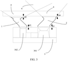
FIG. 3 is a schematic structural diagram 3 of a terminal according to an embodiment of the present disclosure. - The following clearly and completely describes the technical solutions in the embodiments of the present disclosure with reference to the accompanying drawings in the embodiments of the present disclosure. Apparently, the described embodiments are some but not all of the embodiments of the present disclosure. All other embodiments obtained by a person of ordinary skill in the art based on the embodiments of the present disclosure without creative efforts shall fall within the protection scope of the present disclosure.
- An embodiment of the present disclosure provides a terminal. As shown in
FIG. 1 to FIG. 3 , the terminal includes: - a
glass cover plate 4; - an
infrared sensor 3, where theinfrared sensor 3 includes atransmitter 302 and areceiver 301; and - a first
light guide structure 1 and/or a secondlight guide structure 2, where the firstlight guide structure 1 is fixed between thetransmitter 302 and theglass cover plate 4, and the secondlight guide structure 2 is fixed between thereceiver 301 and theglass cover plate 4; - the first
light guide structure 1 obliquely extends from a light emitting surface of thetransmitter 302 toward theglass cover plate 4, and an oblique direction is away from an orthographic projection of thereceiver 301 on theglass cover plate 4; and - the second
light guide structure 2 obliquely extends from a light emitting surface of thereceiver 301 toward theglass cover plate 4, and an oblique direction is away from an orthographic projection of thetransmitter 302 on theglass cover plate 4. - It can be learned that in this embodiment of the present disclosure, a light guide structure is added between the transmitter of the infrared sensor and the glass cover plate and/or between the receiver of the infrared sensor and the glass cover plate, so that an actual emission window and/or a receive window extend toward a remote end of each other. In this way, an amount of light emitted from the transmitter of the infrared sensor is reflected by a surface of the glass cover plate facing the infrared sensor to enter the receiver is reduced, thereby reducing background noise of the infrared sensor.
- Further, a nearest distance between the
infrared sensor 3 and atarget overlapping area 6 is greater than a distance between a first surface of theglass cover plate 4 and theinfrared sensor 3, and the first surface is a surface of theglass cover plate 4 facing theinfrared sensor 3; and
thetarget overlapping area 6 is an overlapping area of an opening angle of the firstlight guide structure 1 facing theglass cover plate 4 and a receiving angle of thereceiver 301, or an overlapping area of an opening angle of the secondlight guide structure 2 facing theglass cover plate 4 and an emission angle of thetransmitter 302, or an overlapping area of the opening angle of the firstlight guide structure 1 facing theglass cover plate 4 and the opening angle of the secondlight guide structure 2 facing theglass cover plate 4. - Specifically, as shown in
FIG. 1 , when the firstlight guide structure 1 is added between thetransmitter 302 of theinfrared emitter 3 and theglass cover plate 4, a light guide action of the firstlight guide structure 1 is used, so that an actual emission window of theinfrared sensor 3 extends in a direction away from a receive window. In this way, an overlapping area of the actual emission window and the receive window is located above a surface of theglass cover plate 4 facing theinfrared sensor 3, that is, light emitted by thetransmitter 302 of theinfrared sensor 3 is not reflected by the surface of theglass cover plate 4 facing theinfrared sensor 3 to enter thereceiver 301, thereby reducing background noise of theinfrared sensor 3. In addition, an emission field of view (FOV) may be increased by increasing an angle of a light emitting opening at an upper end of the firstlight guide structure 1. - As shown in
FIG. 2 , when the secondlight guide structure 2 is added between thereceiver 301 of theinfrared emitter 3 and theglass cover plate 4, a light guide action of the secondlight guide structure 2 is used, so that an actual receive window of theinfrared sensor 3 extends in a direction away from an emission window. In this way, an overlapping area of the actual receive window and the emission window is located above a surface of theglass cover plate 4 facing theinfrared sensor 3, that is, light emitted by thetransmitter 302 of theinfrared sensor 3 is not reflected by the surface of theglass cover plate 4 facing theinfrared sensor 3 to enter thereceiver 301, thereby reducing background noise of theinfrared sensor 3. In addition, a receiving FOV may be increased by adjusting an angle of an opening of the secondlight guide structure 2 facing theglass cover plate 4. - As shown in
FIG. 3 , when the firstlight guide structure 1 is added between thetransmitter 302 of theinfrared emitter 3 and theglass cover plate 4, and the secondlight guide structure 2 is added between thereceiver 301 of theinfrared emitter 3 and theglass cover plate 4, light guide actions of the firstlight guide structure 1 and the secondlight guide structure 2 are used, so that an actual emission window and a receive window extend toward a remote end of each other. In this way, an overlapping area of the actual emission window and the receive window is located above a surface of theglass cover plate 4 facing theinfrared sensor 3, that is, light emitted from thetransmitter 302 of theinfrared sensor 3 is not reflected by the surface of theglass cover plate 4 facing theinfrared sensor 3 to enter thereceiver 301, thereby reducing background noise of theinfrared sensor 3. - Further, the first
light guide structure 1 and/or the secondlight guide structure 2 may further be used, so that a nearest distance between theinfrared sensor 3 and atarget overlapping area 6 is greater than a distance between a second surface of theglass cover plate 4 and theinfrared sensor 3, and the second surface is a surface that is of theglass cover plate 4 and that is away from theinfrared sensor 3. That is, the firstlight guide structure 1 and/or the secondlight guide structure 2 may further be used, so that an actual emission window and/or a receive window extend toward a remote end of each other. In this way, an overlapping area of the actual emission window and the receive window is located above the second surface of theglass cover plate 4. In this way, light emitted from thetransmitter 302 of theinfrared sensor 3 is not reflected by the second surface of theglass cover plate 4 to enter thereceiver 301, thereby preventing oil pollution on the second surface from affecting infrared detection. - Optionally, as shown in
FIG. 1 andFIG. 3 , the firstlight guide structure 1 includes a firstlight guide tube 101 and a secondlight guide tube 102. A first end of the firstlight guide tube 101 faces thetransmitter 302, a second end of the firstlight guide tube 101 is communicated with and fixedly connected to a first end of the secondlight guide tube 102, and a second end of the secondlight guide tube 102 faces theglass cover plate 4. An inner wall of the firstlight guide tube 101 is coated with a specular reflection material, an inner wall of the secondlight guide tube 102 is coated with a light absorbing material, and an included angle between an axis of the firstlight guide tube 101 and a facing direction of thetransmitter 302 is greater than 0° and less than 90°. - Both the first
light guide tube 101 and the secondlight guide tube 102 are made of an opaque material. In addition, the firstlight guide tube 101 and the secondlight guide tube 102 may be hollow, or may be filled with a transparent light guide material. - Further, as shown in
FIG. 1 andFIG. 3 , a difference between an angle 45° and the included angle between the axis of the firstlight guide tube 101 and the facing direction of thetransmitter 302 is within a preset range. That is, an opening plane of the first end of the secondlight guide tube 102 and the firstlight guide tube 101 are at an angle of 45°, so that light emitted from thetransmitter 302 may be reflected through a sidewall of the firstlight guide tube 101 and then emitted vertically. - Further, as shown in
FIG. 1 andFIG. 3 , the secondlight guide tube 102 is horn-shaped, and a horn opening faces theglass cover plate 4. The secondlight guide tube 102 is horn-shaped and is configured to constrain an emission angle of an infrared ray that passes through the firstlight guide structure 1, and an opening angle thereof may be adjusted based on a requirement on the emission angle in actual application. - Optionally, as shown in
FIG. 1 andFIG. 3 , the firstlight guide structure 1 further includes a first transitionlight guide tube 103, a first end of the first transitionlight guide tube 103 faces thetransmitter 302, a second end of the first transitionlight guide tube 103 is communicated with and fixedly connected to the first end of the firstlight guide tube 101, an inner wall of the first transitionlight guide tube 103 is coated with a specular reflection material, and an axis of the first transitionlight guide tube 103 is parallel to the facing direction of thetransmitter 302. - Optionally, as shown in
FIG. 1 andFIG. 3 , the firstlight guide structure 1 further includes a second transitionlight guide tube 104, a first end of the second transitionlight guide tube 104 is communicated with and fixedly connected to the second end of the firstlight guide tube 101, a second end of the second transitionlight guide tube 104 is communicated with and fixedly connected to the first end of the secondlight guide tube 102, an inner wall of the second transitionlight guide tube 104 is coated with a specular reflection material, and an axis of the second transitionlight guide tube 104 is parallel to the facing direction of thetransmitter 302. - The first transition
light guide tube 103 and the second transitionlight guide tube 104 are configured to adjust an overall length of the firstlight guide structure 1, to be applicable to different distances between theglass cover plate 4 and theinfrared emitter 3, thereby extending an application range of the firstlight guide structure 1. - Optionally, as shown in
FIG. 2 andFIG. 3 , the secondlight guide structure 2 includes a thirdlight guide tube 201 and a fourthlight guide tube 202. A first end of the thirdlight guide tube 201 faces thereceiver 301, a second end of the thirdlight guide tube 201 is communicated with and fixedly connected to a first end of the fourthlight guide tube 202, and a second end of the fourthlight guide tube 202 faces theglass cover plate 4. An inner wall of the thirdlight guide tube 201 is coated with a specular reflection material, an inner wall of the fourthlight guide tube 202 is coated with a reflection material, and an included angle between an axis of the thirdlight guide tube 201 and a facing direction of thereceiver 301 is greater than 0° and less than 90°. - Both the third
light guide tube 201 and the fourthlight guide tube 202 are made of an opaque material. In addition, the thirdlight guide tube 201 and the fourthlight guide tube 202 may be hollow, or may be filled with a transparent light guide material. - Further, as shown in
FIG. 2 andFIG. 3 , a difference between an angle 45° and the included angle between the axis of the thirdlight guide tube 201 and the facing direction of thereceiver 301 is within a preset range. That is, an opening plane of the first end of the fourthlight guide tube 202 and the thirdlight guide tube 201 are at an angle of 45°, so that external light may be reflected through a sidewall of the thirdlight guide tube 201 and then vertically enter thereceiver 301. - Further, as shown in
FIG. 2 andFIG. 3 , the fourthlight guide tube 202 is horn-shaped, and a horn opening faces theglass cover plate 4. The fourthlight guide tube 202 is horn-shaped and is configured to constrain a receiving angle of an infrared ray that passes through the secondlight guide structure 2, and an opening angle thereof may be adjusted based on a requirement on the receiving angle in actual application. - Further, the reflection material coated on the inner wall of the fourth
light guide tube 202 is a specular reflection material, so that light in more directions can enter thereceiver 301, and coverage of received light is increased. - Optionally, as shown in
FIG. 2 andFIG. 3 , the secondlight guide structure 2 further includes a third transitionlight guide tube 203, a first end of the third transitionlight guide tube 203 faces thereceiver 301, a second end of the third transitionlight guide tube 203 is communicated with and fixedly connected to the first end of the thirdlight guide tube 201, an inner wall of the third transitionlight guide tube 203 is coated with a specular reflection material, and an axis of the third transitionlight guide tube 203 is parallel to the facing direction of thereceiver 301. - Optionally, as shown in
FIG. 2 andFIG. 3 , the secondlight guide structure 2 further includes a fourth transitionlight guide tube 204, a first end of the fourth transitionlight guide tube 204 is communicated with and fixedly connected to the second end of the thirdlight guide tube 201, a second end of the fourth transitionlight guide tube 204 is communicated with and fixedly connected to the first end of the fourthlight guide tube 202, an inner wall of the fourth transitionlight guide tube 204 is coated with a specular reflection material, and an axis of the fourth transitionlight guide tube 204 is parallel to the facing direction of thereceiver 301. - The third transition
light guide tube 203 and the fourth transitionlight guide tube 204 are configured to adjust an overall length of the secondlight guide structure 2, to be applicable to different distances between theglass cover plate 4 and theinfrared emitter 3, thereby extending an application range of the secondlight guide structure 2. - Optionally, the terminal further includes a support structure, where the support structure is located between the
glass cover plate 4 and theinfrared sensor 3, and the firstlight guide structure 1 and/or the secondlight guide structure 2 are/is fixed on the support structure. The firstlight guide structure 1 and/or the secondlight guide structure 2 are fixed on the support structure, to prevent movement of the firstlight guide structure 1 and/or the secondlight guide structure 2 from affecting a light guide action. - Optionally, the first
light guide structure 1 is spaced from thetransmitter 302 by a first preset distance d1, and the firstlight guide structure 1 is spaced from theglass cover plate 4 by a second preset distance d2. That is, an assembly distance is reserved between the firstlight guide structure 1, and thetransmitter 302 and theglass cover plate 4, to prevent damage to the firstlight guide structure 1 in an assembly process. - Optionally, the second
light guide structure 2 is spaced from thereceiver 301 by a third preset distance d3, and the secondlight guide structure 2 is spaced from theglass cover plate 4 by a fourth preset distance d4. That is, an assembly distance is reserved between the secondlight guide structure 2, and thetransmitter 302 and theglass cover plate 4, to prevent damage to the secondlight guide structure 2 in an assembly process. - In addition, when there is an assemble error between a light pore of the
transmitter 302 of theinfrared emitter 3 and thetransmitter 302 on theglass cover plate 4, the firstlight guide structure 1 may be used for correction. Likewise, when there is an assemble error between a light pore of thereceiver 301 of theinfrared emitter 3 and thereceiver 301 on theglass cover plate 4, the secondlight guide structure 2 may be used for correction. - In addition, for the second
light guide structure 2 mentioned above, an orthographic end of a light receiver that is used to detect light intensity may be further mounted. In this case, an FOV may be increased by increasing an angle of a light emitting opening at an upper end of the secondlight guide structure 2, so that a light-sensitive detection direction is greater. - The foregoing descriptions are merely optional implementations of the present disclosure. It should be noted that a person of ordinary skill in the art may make several improvements and polishing without departing from the principle of the present disclosure and the improvements and polishing shall fall within the protection scope of the present disclosure.
Claims (15)
- A terminal, comprising:a glass cover plate;an infrared sensor, wherein the infrared sensor comprises a transmitter and a receiver; anda first light guide structure and/or a second light guide structure, wherein the first light guide structure is fixed between the transmitter and the glass cover plate, and the second light guide structure is fixed between the receiver and the glass cover plate;the first light guide structure obliquely extends from a light emitting surface of the transmitter toward the glass cover plate, and an oblique direction is away from an orthographic projection of the receiver on the glass cover plate; andthe second light guide structure obliquely extends from a light emitting surface of the receiver toward the glass cover plate, and an oblique direction is away from an orthographic projection of the transmitter on the glass cover plate.
- The terminal according to claim 1, wherein a nearest distance between the infrared sensor and a target overlapping area is greater than a distance between a first surface of the glass cover plate and the infrared sensor, and the first surface is a surface of the glass cover plate facing the infrared sensor; and
the target overlapping area is an overlapping area of an opening angle of the first light guide structure facing the glass cover plate and a receiving angle of the receiver, or an overlapping area of an opening angle of the second light guide structure facing the glass cover plate and an emission angle of the transmitter, or an overlapping area of the opening angle of the first light guide structure facing the glass cover plate and the opening angle of the second light guide structure facing the glass cover plate. - The terminal according to claim 1, wherein the first light guide structure comprises a first light guide tube and a second light guide tube, a first end of the first light guide tube faces the transmitter, a second end of the first light guide tube is communicated with and fixedly connected to a first end of the second light guide tube, and a second end of the second light guide tube faces the glass cover plate; and
an inner wall of the first light guide tube is coated with a specular reflection material, an inner wall of the second light guide tube is coated with a light absorbing material, and an included angle between an axis of the first light guide tube and a facing direction of the transmitter is greater than 0° and less than 90°. - The terminal according to claim 3, wherein the first light guide structure further comprises a first transition light guide tube, a first end of the first transition light guide tube faces the transmitter, a second end of the first transition light guide tube is communicated with and fixedly connected to the first end of the first light guide tube, an inner wall of the first transition light guide tube is coated with a specular reflection material, and an axis of the first transition light guide tube is parallel to the facing direction of the transmitter.
- The terminal according to claim 3, wherein the first light guide structure further comprises a second transition light guide tube, a first end of the second transition light guide tube is communicated with and fixedly connected to the second end of the first light guide tube, a second end of the second transition light guide tube is communicated with and fixedly connected to the first end of the second light guide tube, an inner wall of the second transition light guide tube is coated with a specular reflection material, and an axis of the second transition light guide tube is parallel to the facing direction of the transmitter.
- The terminal according to claim 3, wherein a difference between an angle 45° and the included angle between the axis of the first light guide tube and the facing direction of the transmitter is within a preset range.
- The terminal according to claim 3, wherein the second light guide tube is horn-shaped, and a horn opening faces the glass cover plate.
- The terminal according to claim 1, wherein the second light guide structure comprises a third light guide tube and a fourth light guide tube, a first end of the third light guide tube faces the receiver, a second end of the third light guide tube is communicated with and fixedly connected to a first end of the fourth light guide tube, and a second end of the fourth light guide tube faces the glass cover plate; and
an inner wall of the third light guide tube is coated with a specular reflection material, an inner wall of the fourth light guide tube is coated with a reflection material, and an included angle between an axis of the third light guide tube and a facing direction of the receiver is greater than 0° and less than 90°. - The terminal according to claim 8, wherein the second light guide structure further comprises a third transition light guide tube, a first end of the third transition light guide tube faces the receiver, a second end of the third transition light guide tube is communicated with and fixedly connected to the first end of the third light guide tube, an inner wall of the third transition light guide tube is coated with a specular reflection material, and an axis of the third transition light guide tube is parallel to the facing direction of the receiver.
- The terminal according to claim 8, wherein the second light guide structure further comprises a fourth transition light guide tube, a first end of the fourth transition light guide tube is communicated with and fixedly connected to the second end of the third light guide tube, a second end of the fourth transition light guide tube is communicated with and fixedly connected to the first end of the fourth light guide tube, an inner wall of the fourth transition light guide tube is coated with a specular reflection material, and an axis of the fourth transition light guide tube is parallel to the facing direction of the receiver.
- The terminal according to claim 8, wherein a difference between an angle 45° and the included angle between the axis of the third light guide tube and the facing direction of the receiver is within a preset range.
- The terminal according to claim 8, wherein the fourth light guide tube is horn-shaped, and a horn opening faces the glass cover plate.
- The terminal according to claim 8, wherein the reflection material coated on the inner wall of the fourth light guide tube is a specular reflection material.
- The terminal according to claim 1, further comprising a support structure, wherein the support structure is located between the glass cover plate and the infrared sensor, and the first light guide structure and/or the second light guide structure are/is fixed on the support structure.
- The terminal according to claim 1, wherein the first light guide structure is spaced from the transmitter by a first preset distance, and the first light guide structure is spaced from the glass cover plate by a second preset distance; and
the second light guide structure is spaced from the receiver by a third preset distance, and the second light guide structure is spaced from the glass cover plate by a fourth preset distance.
Applications Claiming Priority (2)
| Application Number | Priority Date | Filing Date | Title |
|---|---|---|---|
| CN201910335071.XA CN110333515B (en) | 2019-04-24 | 2019-04-24 | Terminal |
| PCT/CN2020/085653 WO2020216184A1 (en) | 2019-04-24 | 2020-04-20 | Terminal |
Publications (3)
| Publication Number | Publication Date |
|---|---|
| EP3961248A1 true EP3961248A1 (en) | 2022-03-02 |
| EP3961248A4 EP3961248A4 (en) | 2022-06-01 |
| EP3961248B1 EP3961248B1 (en) | 2025-07-16 |
Family
ID=68139336
Family Applications (1)
| Application Number | Title | Priority Date | Filing Date |
|---|---|---|---|
| EP20795909.9A Active EP3961248B1 (en) | 2019-04-24 | 2020-04-20 | Terminal |
Country Status (5)
| Country | Link |
|---|---|
| US (1) | US12504536B2 (en) |
| EP (1) | EP3961248B1 (en) |
| CN (1) | CN110333515B (en) |
| ES (1) | ES3038146T3 (en) |
| WO (1) | WO2020216184A1 (en) |
Families Citing this family (8)
| Publication number | Priority date | Publication date | Assignee | Title |
|---|---|---|---|---|
| CN109801937A (en) * | 2019-01-28 | 2019-05-24 | 京东方科技集团股份有限公司 | Visible light communication device and preparation method thereof, visible light communication system |
| CN110333515B (en) | 2019-04-24 | 2022-03-29 | 维沃移动通信有限公司 | Terminal |
| CN113890908B (en) * | 2020-07-01 | 2024-04-05 | 深圳市万普拉斯科技有限公司 | Electronic equipment |
| CN114554007B (en) * | 2020-11-25 | 2023-04-11 | 珠海格力电器股份有限公司 | Proximity sensor of mobile terminal, mobile terminal and control method of mobile terminal |
| CN115695596B (en) * | 2021-07-23 | 2025-09-02 | 北京小米移动软件有限公司 | Light guide structure and terminal equipment |
| CN115733907B (en) * | 2021-09-01 | 2025-07-25 | 北京小米移动软件有限公司 | Terminal |
| CN114660689A (en) * | 2022-03-07 | 2022-06-24 | 维沃移动通信有限公司 | Electronic equipment |
| JPWO2024111480A1 (en) * | 2022-11-21 | 2024-05-30 |
Family Cites Families (27)
| Publication number | Priority date | Publication date | Assignee | Title |
|---|---|---|---|---|
| US7485843B2 (en) * | 2006-03-31 | 2009-02-03 | Masstech Group Inc. | Touch/proximity-sensing using reflective optical sensor and a light pipe for specularly reflecting light |
| EP2235961A1 (en) * | 2007-12-19 | 2010-10-06 | Koninklijke Philips Electronics N.V. | Loudspeaker cover |
| US8384559B2 (en) | 2010-04-13 | 2013-02-26 | Silicon Laboratories Inc. | Sensor device with flexible interface and updatable information store |
| DE112011105262B4 (en) * | 2011-05-19 | 2025-10-16 | OSRAM Opto Semiconductors Gesellschaft mit beschränkter Haftung | Optoelectronic device and method for producing optoelectronic devices |
| JP2013211507A (en) * | 2011-08-08 | 2013-10-10 | Rohm Co Ltd | Photointerrupter, manufacturing method of photointerrupter, and mounting structure of photointerrupter |
| US8912480B2 (en) * | 2011-08-31 | 2014-12-16 | Apple Inc. | Light sensor systems for electronic devices |
| TWI453923B (en) * | 2012-06-22 | 2014-09-21 | 台灣晶技股份有限公司 | Light sensing chip package structure |
| US8946620B2 (en) * | 2012-10-16 | 2015-02-03 | Avago Technologies General Ip (Singapore) Pte. Ltd. | Proximity sensor device with internal channeling section |
| DE202013100781U1 (en) | 2013-02-21 | 2013-03-13 | Precaster Enterprises Co., Ltd. | Structure of an optical path for a laser rangefinder |
| CN105527627A (en) | 2016-01-18 | 2016-04-27 | 深圳市金立通信设备有限公司 | Laser ranging device, camera device and terminal |
| KR20170115425A (en) * | 2016-04-07 | 2017-10-17 | 크루셜텍 (주) | Distance measuring sensor assembly and electronic equipment having the same |
| CN106353767A (en) | 2016-09-12 | 2017-01-25 | 深圳市金立通信设备有限公司 | Laser distance measurement device, photographic device and terminal |
| CN206490700U (en) * | 2016-12-06 | 2017-09-12 | 广东欧珀移动通信有限公司 | Sensor cluster and terminal |
| CN206332707U (en) * | 2016-12-06 | 2017-07-14 | 广东欧珀移动通信有限公司 | Sensor cluster and terminal |
| CN107064906B (en) | 2016-12-12 | 2023-07-14 | 东莞市美光达光学科技有限公司 | Ranging lens module and laser ranging device |
| CN106933415B (en) * | 2017-03-07 | 2019-11-26 | Oppo广东移动通信有限公司 | Sensor assembly and terminal |
| CN211740119U (en) * | 2017-09-28 | 2020-10-23 | 茂势达有限公司 | Distance measuring sensor |
| CN109655840A (en) | 2017-10-10 | 2019-04-19 | 鸿富锦精密工业(深圳)有限公司 | Scanning type laser radar |
| CN107835272A (en) * | 2017-10-31 | 2018-03-23 | 珠海市魅族科技有限公司 | A kind of mobile terminal |
| CN108616616B (en) * | 2018-04-03 | 2021-02-19 | 北京小米移动软件有限公司 | Mobile terminal |
| CN108828612B (en) * | 2018-04-23 | 2021-03-09 | 北京小米移动软件有限公司 | Distance sensing components and mobile terminals |
| CN108493185A (en) * | 2018-05-25 | 2018-09-04 | 矽力杰半导体技术(杭州)有限公司 | Optical sensing system and electronic display system |
| CN208721790U (en) | 2018-05-29 | 2019-04-09 | 维沃移动通信有限公司 | A kind of terminal device |
| CN108989494B (en) * | 2018-06-27 | 2021-02-09 | 北京小米移动软件有限公司 | Electronic equipment |
| CN108898951A (en) * | 2018-07-27 | 2018-11-27 | 维沃移动通信有限公司 | a mobile terminal |
| CN109218472B (en) * | 2018-08-29 | 2020-09-25 | 维沃移动通信有限公司 | Terminal equipment |
| CN110333515B (en) * | 2019-04-24 | 2022-03-29 | 维沃移动通信有限公司 | Terminal |
-
2019
- 2019-04-24 CN CN201910335071.XA patent/CN110333515B/en active Active
-
2020
- 2020-04-20 ES ES20795909T patent/ES3038146T3/en active Active
- 2020-04-20 EP EP20795909.9A patent/EP3961248B1/en active Active
- 2020-04-20 WO PCT/CN2020/085653 patent/WO2020216184A1/en not_active Ceased
-
2021
- 2021-10-19 US US17/505,490 patent/US12504536B2/en active Active
Also Published As
| Publication number | Publication date |
|---|---|
| EP3961248B1 (en) | 2025-07-16 |
| US20220035033A1 (en) | 2022-02-03 |
| ES3038146T3 (en) | 2025-10-09 |
| US12504536B2 (en) | 2025-12-23 |
| EP3961248A4 (en) | 2022-06-01 |
| CN110333515B (en) | 2022-03-29 |
| CN110333515A (en) | 2019-10-15 |
| WO2020216184A1 (en) | 2020-10-29 |
Similar Documents
| Publication | Publication Date | Title |
|---|---|---|
| US12504536B2 (en) | Terminal | |
| CN107918118B (en) | Laser radar | |
| US20220171028A1 (en) | Flash lidar | |
| EP4071514A1 (en) | Laser ranging device and robot | |
| CN106453723B (en) | Sensor assembly and terminal | |
| CN101656011A (en) | Universal smoke fire detector | |
| WO2021109912A1 (en) | Laser distance measurement device and robot | |
| JP2019138675A (en) | Object detecting device | |
| KR102884694B1 (en) | Lidar Sensor that measures horizontal angle using step difference and light reflectance | |
| US20110226952A1 (en) | Reflection Sensing System | |
| CN205450271U (en) | Scanning distance measuring equipment | |
| CN114442069A (en) | Laser detection module and laser radar | |
| CN210294045U (en) | Carbon dioxide sensing device and light reflection mechanism | |
| EP3779412B1 (en) | Self-calibrating weak light detection device and use thereof | |
| CN217846621U (en) | Laser receiving module with adjustable diaphragm and laser radar | |
| JP2017125765A (en) | Object detection device | |
| CN220207854U (en) | Photoelectric sensor | |
| EP4589335A1 (en) | Attenuation wall to reduce optical noise in an optical ranging sensor | |
| CN1237339C (en) | Vertical backward scattering type photoelectric smoke detector | |
| CN113985385A (en) | Laser radar | |
| CN212645739U (en) | photoelectric sensor | |
| CN119335612B (en) | An SMT tray detection component and its parameter calculation method | |
| CN111060894A (en) | Receiving lens, coaxial radar laser receiving and transmitting system structure of TOF and product | |
| CN218412887U (en) | Laser receiving module with electronic glass and laser radar | |
| CN219320512U (en) | Mini background suppression photoelectric sensor |
Legal Events
| Date | Code | Title | Description |
|---|---|---|---|
| STAA | Information on the status of an ep patent application or granted ep patent |
Free format text: STATUS: THE INTERNATIONAL PUBLICATION HAS BEEN MADE |
|
| PUAI | Public reference made under article 153(3) epc to a published international application that has entered the european phase |
Free format text: ORIGINAL CODE: 0009012 |
|
| STAA | Information on the status of an ep patent application or granted ep patent |
Free format text: STATUS: REQUEST FOR EXAMINATION WAS MADE |
|
| 17P | Request for examination filed |
Effective date: 20211119 |
|
| AK | Designated contracting states |
Kind code of ref document: A1 Designated state(s): AL AT BE BG CH CY CZ DE DK EE ES FI FR GB GR HR HU IE IS IT LI LT LU LV MC MK MT NL NO PL PT RO RS SE SI SK SM TR |
|
| A4 | Supplementary search report drawn up and despatched |
Effective date: 20220503 |
|
| RIC1 | Information provided on ipc code assigned before grant |
Ipc: H04M 1/02 20060101ALI20220426BHEP Ipc: G01S 17/04 20200101ALI20220426BHEP Ipc: G01S 7/481 20060101AFI20220426BHEP |
|
| DAV | Request for validation of the european patent (deleted) | ||
| DAX | Request for extension of the european patent (deleted) | ||
| GRAP | Despatch of communication of intention to grant a patent |
Free format text: ORIGINAL CODE: EPIDOSNIGR1 |
|
| STAA | Information on the status of an ep patent application or granted ep patent |
Free format text: STATUS: GRANT OF PATENT IS INTENDED |
|
| INTG | Intention to grant announced |
Effective date: 20250324 |
|
| GRAS | Grant fee paid |
Free format text: ORIGINAL CODE: EPIDOSNIGR3 |
|
| GRAA | (expected) grant |
Free format text: ORIGINAL CODE: 0009210 |
|
| STAA | Information on the status of an ep patent application or granted ep patent |
Free format text: STATUS: THE PATENT HAS BEEN GRANTED |
|
| AK | Designated contracting states |
Kind code of ref document: B1 Designated state(s): AL AT BE BG CH CY CZ DE DK EE ES FI FR GB GR HR HU IE IS IT LI LT LU LV MC MK MT NL NO PL PT RO RS SE SI SK SM TR |
|
| REG | Reference to a national code |
Ref country code: GB Ref legal event code: FG4D |
|
| REG | Reference to a national code |
Ref country code: CH Ref legal event code: EP Ref country code: DE Ref legal event code: R096 Ref document number: 602020054663 Country of ref document: DE |
|
| REG | Reference to a national code |
Ref country code: IE Ref legal event code: FG4D |
|
| REG | Reference to a national code |
Ref country code: NL Ref legal event code: FP |
|
| REG | Reference to a national code |
Ref country code: ES Ref legal event code: FG2A Ref document number: 3038146 Country of ref document: ES Kind code of ref document: T3 Effective date: 20251009 |
|
| PG25 | Lapsed in a contracting state [announced via postgrant information from national office to epo] |
Ref country code: PT Free format text: LAPSE BECAUSE OF FAILURE TO SUBMIT A TRANSLATION OF THE DESCRIPTION OR TO PAY THE FEE WITHIN THE PRESCRIBED TIME-LIMIT Effective date: 20251117 |
|
| REG | Reference to a national code |
Ref country code: AT Ref legal event code: MK05 Ref document number: 1814496 Country of ref document: AT Kind code of ref document: T Effective date: 20250716 |
|
| PG25 | Lapsed in a contracting state [announced via postgrant information from national office to epo] |
Ref country code: IS Free format text: LAPSE BECAUSE OF FAILURE TO SUBMIT A TRANSLATION OF THE DESCRIPTION OR TO PAY THE FEE WITHIN THE PRESCRIBED TIME-LIMIT Effective date: 20251116 |
|
| PG25 | Lapsed in a contracting state [announced via postgrant information from national office to epo] |
Ref country code: NO Free format text: LAPSE BECAUSE OF FAILURE TO SUBMIT A TRANSLATION OF THE DESCRIPTION OR TO PAY THE FEE WITHIN THE PRESCRIBED TIME-LIMIT Effective date: 20251016 |
|
| REG | Reference to a national code |
Ref country code: LT Ref legal event code: MG9D |
|
| PG25 | Lapsed in a contracting state [announced via postgrant information from national office to epo] |
Ref country code: AT Free format text: LAPSE BECAUSE OF FAILURE TO SUBMIT A TRANSLATION OF THE DESCRIPTION OR TO PAY THE FEE WITHIN THE PRESCRIBED TIME-LIMIT Effective date: 20250716 |
|
| PG25 | Lapsed in a contracting state [announced via postgrant information from national office to epo] |
Ref country code: FI Free format text: LAPSE BECAUSE OF FAILURE TO SUBMIT A TRANSLATION OF THE DESCRIPTION OR TO PAY THE FEE WITHIN THE PRESCRIBED TIME-LIMIT Effective date: 20250716 |
|
| PG25 | Lapsed in a contracting state [announced via postgrant information from national office to epo] |
Ref country code: HR Free format text: LAPSE BECAUSE OF FAILURE TO SUBMIT A TRANSLATION OF THE DESCRIPTION OR TO PAY THE FEE WITHIN THE PRESCRIBED TIME-LIMIT Effective date: 20250716 |
|
| PG25 | Lapsed in a contracting state [announced via postgrant information from national office to epo] |
Ref country code: GR Free format text: LAPSE BECAUSE OF FAILURE TO SUBMIT A TRANSLATION OF THE DESCRIPTION OR TO PAY THE FEE WITHIN THE PRESCRIBED TIME-LIMIT Effective date: 20251017 |
|
| PG25 | Lapsed in a contracting state [announced via postgrant information from national office to epo] |
Ref country code: SE Free format text: LAPSE BECAUSE OF FAILURE TO SUBMIT A TRANSLATION OF THE DESCRIPTION OR TO PAY THE FEE WITHIN THE PRESCRIBED TIME-LIMIT Effective date: 20250716 |
|
| PG25 | Lapsed in a contracting state [announced via postgrant information from national office to epo] |
Ref country code: LV Free format text: LAPSE BECAUSE OF FAILURE TO SUBMIT A TRANSLATION OF THE DESCRIPTION OR TO PAY THE FEE WITHIN THE PRESCRIBED TIME-LIMIT Effective date: 20250716 |
|
| PG25 | Lapsed in a contracting state [announced via postgrant information from national office to epo] |
Ref country code: BG Free format text: LAPSE BECAUSE OF FAILURE TO SUBMIT A TRANSLATION OF THE DESCRIPTION OR TO PAY THE FEE WITHIN THE PRESCRIBED TIME-LIMIT Effective date: 20250716 Ref country code: PL Free format text: LAPSE BECAUSE OF FAILURE TO SUBMIT A TRANSLATION OF THE DESCRIPTION OR TO PAY THE FEE WITHIN THE PRESCRIBED TIME-LIMIT Effective date: 20250716 |
|
| PG25 | Lapsed in a contracting state [announced via postgrant information from national office to epo] |
Ref country code: RS Free format text: LAPSE BECAUSE OF FAILURE TO SUBMIT A TRANSLATION OF THE DESCRIPTION OR TO PAY THE FEE WITHIN THE PRESCRIBED TIME-LIMIT Effective date: 20251016 |
|
| PG25 | Lapsed in a contracting state [announced via postgrant information from national office to epo] |
Ref country code: SM Free format text: LAPSE BECAUSE OF FAILURE TO SUBMIT A TRANSLATION OF THE DESCRIPTION OR TO PAY THE FEE WITHIN THE PRESCRIBED TIME-LIMIT Effective date: 20250716 |
|
| PGFP | Annual fee paid to national office [announced via postgrant information from national office to epo] |
Ref country code: GB Payment date: 20260303 Year of fee payment: 7 |
|
| PG25 | Lapsed in a contracting state [announced via postgrant information from national office to epo] |
Ref country code: DK Free format text: LAPSE BECAUSE OF FAILURE TO SUBMIT A TRANSLATION OF THE DESCRIPTION OR TO PAY THE FEE WITHIN THE PRESCRIBED TIME-LIMIT Effective date: 20250716 |
|
| PGFP | Annual fee paid to national office [announced via postgrant information from national office to epo] |
Ref country code: IT Payment date: 20260320 Year of fee payment: 7 |
|
| PGFP | Annual fee paid to national office [announced via postgrant information from national office to epo] |
Ref country code: NL Payment date: 20260317 Year of fee payment: 7 |
|
| PGFP | Annual fee paid to national office [announced via postgrant information from national office to epo] |
Ref country code: FR Payment date: 20260309 Year of fee payment: 7 |
|
| PG25 | Lapsed in a contracting state [announced via postgrant information from national office to epo] |
Ref country code: CZ Free format text: LAPSE BECAUSE OF FAILURE TO SUBMIT A TRANSLATION OF THE DESCRIPTION OR TO PAY THE FEE WITHIN THE PRESCRIBED TIME-LIMIT Effective date: 20250716 |
|
| PG25 | Lapsed in a contracting state [announced via postgrant information from national office to epo] |
Ref country code: EE Free format text: LAPSE BECAUSE OF FAILURE TO SUBMIT A TRANSLATION OF THE DESCRIPTION OR TO PAY THE FEE WITHIN THE PRESCRIBED TIME-LIMIT Effective date: 20250716 Ref country code: SK Free format text: LAPSE BECAUSE OF FAILURE TO SUBMIT A TRANSLATION OF THE DESCRIPTION OR TO PAY THE FEE WITHIN THE PRESCRIBED TIME-LIMIT Effective date: 20250716 |