EP3961235B1 - Verfahren, gerät, vorrichtung und medium zur erkennung eines internen kurzschlussfehlers einer batteriezelle - Google Patents
Verfahren, gerät, vorrichtung und medium zur erkennung eines internen kurzschlussfehlers einer batteriezelle Download PDFInfo
- Publication number
- EP3961235B1 EP3961235B1 EP21800970.2A EP21800970A EP3961235B1 EP 3961235 B1 EP3961235 B1 EP 3961235B1 EP 21800970 A EP21800970 A EP 21800970A EP 3961235 B1 EP3961235 B1 EP 3961235B1
- Authority
- EP
- European Patent Office
- Prior art keywords
- battery cell
- parameter
- internal short
- target
- battery
- Prior art date
- Legal status (The legal status is an assumption and is not a legal conclusion. Google has not performed a legal analysis and makes no representation as to the accuracy of the status listed.)
- Active
Links
Images


Classifications
-
- G—PHYSICS
- G01—MEASURING; TESTING
- G01R—MEASURING ELECTRIC VARIABLES; MEASURING MAGNETIC VARIABLES
- G01R31/00—Arrangements for testing electric properties; Arrangements for locating electric faults; Arrangements for electrical testing characterised by what is being tested not provided for elsewhere
- G01R31/36—Arrangements for testing, measuring or monitoring the electrical condition of accumulators or electric batteries, e.g. capacity or state of charge [SoC]
- G01R31/392—Determining battery ageing or deterioration, e.g. state of health
-
- G—PHYSICS
- G01—MEASURING; TESTING
- G01R—MEASURING ELECTRIC VARIABLES; MEASURING MAGNETIC VARIABLES
- G01R31/00—Arrangements for testing electric properties; Arrangements for locating electric faults; Arrangements for electrical testing characterised by what is being tested not provided for elsewhere
- G01R31/50—Testing of electric apparatus, lines, cables or components for short-circuits, continuity, leakage current or incorrect line connections
- G01R31/52—Testing for short-circuits, leakage current or ground faults
-
- G—PHYSICS
- G01—MEASURING; TESTING
- G01R—MEASURING ELECTRIC VARIABLES; MEASURING MAGNETIC VARIABLES
- G01R31/00—Arrangements for testing electric properties; Arrangements for locating electric faults; Arrangements for electrical testing characterised by what is being tested not provided for elsewhere
- G01R31/36—Arrangements for testing, measuring or monitoring the electrical condition of accumulators or electric batteries, e.g. capacity or state of charge [SoC]
- G01R31/3644—Constructional arrangements
- G01R31/3648—Constructional arrangements comprising digital calculation means, e.g. for performing an algorithm
-
- G—PHYSICS
- G01—MEASURING; TESTING
- G01R—MEASURING ELECTRIC VARIABLES; MEASURING MAGNETIC VARIABLES
- G01R31/00—Arrangements for testing electric properties; Arrangements for locating electric faults; Arrangements for electrical testing characterised by what is being tested not provided for elsewhere
- G01R31/36—Arrangements for testing, measuring or monitoring the electrical condition of accumulators or electric batteries, e.g. capacity or state of charge [SoC]
- G01R31/367—Software therefor, e.g. for battery testing using modelling or look-up tables
-
- G—PHYSICS
- G01—MEASURING; TESTING
- G01R—MEASURING ELECTRIC VARIABLES; MEASURING MAGNETIC VARIABLES
- G01R31/00—Arrangements for testing electric properties; Arrangements for locating electric faults; Arrangements for electrical testing characterised by what is being tested not provided for elsewhere
- G01R31/36—Arrangements for testing, measuring or monitoring the electrical condition of accumulators or electric batteries, e.g. capacity or state of charge [SoC]
- G01R31/385—Arrangements for measuring battery or accumulator variables
-
- G—PHYSICS
- G01—MEASURING; TESTING
- G01R—MEASURING ELECTRIC VARIABLES; MEASURING MAGNETIC VARIABLES
- G01R31/00—Arrangements for testing electric properties; Arrangements for locating electric faults; Arrangements for electrical testing characterised by what is being tested not provided for elsewhere
- G01R31/36—Arrangements for testing, measuring or monitoring the electrical condition of accumulators or electric batteries, e.g. capacity or state of charge [SoC]
- G01R31/396—Acquisition or processing of data for testing or for monitoring individual cells or groups of cells within a battery
-
- H—ELECTRICITY
- H01—ELECTRIC ELEMENTS
- H01M—PROCESSES OR MEANS, e.g. BATTERIES, FOR THE DIRECT CONVERSION OF CHEMICAL ENERGY INTO ELECTRICAL ENERGY
- H01M10/00—Secondary cells; Manufacture thereof
- H01M10/42—Methods or arrangements for servicing or maintenance of secondary cells or secondary half-cells
- H01M10/4285—Testing apparatus
-
- H—ELECTRICITY
- H01—ELECTRIC ELEMENTS
- H01M—PROCESSES OR MEANS, e.g. BATTERIES, FOR THE DIRECT CONVERSION OF CHEMICAL ENERGY INTO ELECTRICAL ENERGY
- H01M10/00—Secondary cells; Manufacture thereof
- H01M10/42—Methods or arrangements for servicing or maintenance of secondary cells or secondary half-cells
- H01M10/48—Accumulators combined with arrangements for measuring, testing or indicating the condition of cells, e.g. the level or density of the electrolyte
- H01M10/482—Accumulators combined with arrangements for measuring, testing or indicating the condition of cells, e.g. the level or density of the electrolyte for several batteries or cells simultaneously or sequentially
-
- Y—GENERAL TAGGING OF NEW TECHNOLOGICAL DEVELOPMENTS; GENERAL TAGGING OF CROSS-SECTIONAL TECHNOLOGIES SPANNING OVER SEVERAL SECTIONS OF THE IPC; TECHNICAL SUBJECTS COVERED BY FORMER USPC CROSS-REFERENCE ART COLLECTIONS [XRACs] AND DIGESTS
- Y02—TECHNOLOGIES OR APPLICATIONS FOR MITIGATION OR ADAPTATION AGAINST CLIMATE CHANGE
- Y02E—REDUCTION OF GREENHOUSE GAS [GHG] EMISSIONS, RELATED TO ENERGY GENERATION, TRANSMISSION OR DISTRIBUTION
- Y02E60/00—Enabling technologies; Technologies with a potential or indirect contribution to GHG emissions mitigation
- Y02E60/10—Energy storage using batteries
Definitions
- This application relates to the field of, and particularly to a method, apparatus, device and medium for detecting an internal short-circuit fault of a battery cell.
- US2019/181663A1 discloses that a micro short circuit is detected on a basis of a change of a cell voltage or a state of charge during a period of suspension of a charge and discharge.
- WO2017/114195A1 discloses that when the deviation corresponding to any battery is greater than a safe threshold value, it is determined that the battery has an internal short circuit hazard.
- a plurality of' means two or more; the terms “top”, “bottom”, “left”, “right”, “inside”, and “outside” used to indicate orientation or position relationships are only for purpose of facilitating the description of the application and simplifying the description, and do not indicate or imply that a device or element referred to must have a specific orientation, be constructed and operated in a specific orientation, and therefore cannot be understood as limitations to the application.
- the terms “first”, “second”, “third”, etc. are only used for descriptive purposes, and cannot be understood as indicating or implying relative importance.
- Embodiments of the present application provide a method, apparatus, device and medium for detecting an internal short-circuit fault of a battery cell, which can be applied to an application scenario of detecting an internal short-circuit fault of a battery cell in a battery, for example, a specific application scenario of detecting an internal short-circuit fault of a battery cell in a battery that is in a static state, a specific application scenario of detecting an internal short-circuit fault of a battery cell in a battery that is in a charging state, and a specific application scenario of detecting an internal short-circuit fault of a battery cell in a battery that is in a discharging state.
- the battery pack in the embodiments of the present application may be a battery pack in an energy storage apparatus, or may be a battery pack in an electric vehicle.
- Internal short-circuit mainly refers to short-circuit caused by physical contact inside a battery cell.
- the internal short-circuit may be caused by short-circuit due to diaphragm piercing by burrs of a copper foil and an aluminum foil or diaphragm piercing by dendritic crystals of lithium atoms. Since these fine needle-like metals are very thin and have a certain resistance value, a short-circuit current is not necessarily very large.
- the internal short-circuit fault is not discovered in time, it is possible that thermal runaway accidents of sudden rise in battery temperature, smoke, fire or even explosion will be caused by the internal short-circuit, which will seriously affect the battery safety and battery life.
- an internal short-circuit fault occurs in the battery, the market's acceptance of the electric vehicle will be affected seriously.
- Fig. 1 is an exemplary schematic diagram showing voltages of normal battery cells and faulty battery cells changing over time during a charging process of a battery pack with a total of 30 battery cells.
- Fig. 2 is an exemplary schematic diagram showing voltages of normal battery cells and faulty battery cells changing over time during a charging process of a battery pack with a total of 192 battery cells.
- embodiments of the present application provide a scheme for detecting an internal short-circuit fault of a battery cell.
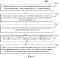
- Fig. 3 is a schematic flowchart of a method for detecting an internal short-circuit fault of a battery provided by an embodiment of the present application. As shown in Fig. 3 , the method 300 for detecting the internal short-circuit fault of the battery of this embodiment may include following steps S310 to S340.
- S310 Electrical signal values at multiple times for each of m battery cells of a battery pack are obtained, when the battery pack is in a preset condition.
- the battery pack may be a battery device including m battery cells, such as a high-voltage battery pack, a low-voltage storage battery, a battery module etc., where m is a positive integer.
- the embodiment of the present application does not limit the specific form of the battery pack.
- the preset condition includes that a current detection is an n th detection of an internal short-circuit fault of a battery cell, where n is a positive integer.
- a current detection is an n th detection of an internal short-circuit fault of a battery cell, where n is a positive integer.
- fault detection results of the first n-1 detection processes may not be taken into consideration, it may be confirmed whether an internal short-circuit fault occurs in a target battery cell using a detection result of the n th detection process.
- the preset condition may further include that a second parameter of the target battery cell is greater than a preset parameter threshold, for each of the first n-1 detection processes of the internal short-circuit fault of the battery cell, where n is an integer greater than 1. That is to say, in the first n detection processes, a second parameter needs to be calculated in each detection process, and the second parameter calculated in each detection process needs to be greater than the preset parameter threshold.
- n in the embodiment of the present application may represent a relative number, and is not limited to the n th detection since the fault detection of the battery pack is started.
- the number of detections may be reset to 0 every preset time period. Alternatively, the number of detections may be reset to 0 when the second parameter is less than the preset parameter threshold in a certain detection process.
- the n fault detections in the embodiments of the present application may be the fault detections when the battery pack is in a static operating condition, a charging operating condition, and a discharging operating condition.
- the preset condition may further include that the battery pack is in a target charging/discharging operating condition. That is to say, the current detection may be the n th fault detection process when the battery is in a charging state or a discharging state.
- the detection method can detect the internal short-circuit fault of the battery cell no matter whether the battery pack is in the static operating condition, charging operating condition, or discharging operating condition. Therefore, the versatility of the detection method can be improved.
- the electrical signal value is then described.
- the electrical signal value is a value of an electrical signal that is different between a normal battery cell and a faulty battery cell. Exemplarily, it may be a voltage value or a current value. In order to facilitate the understanding of the present application, the following part of the embodiments of the present application will mainly use the voltage value as an example for a specific explanation.
- electrical signal values at p times can be obtained. That is to say, m electrical signal values need to be obtained for the i th time of the p times, where p is an integer greater than 1, and i is any positive integer not greater than p .
- S320 For the target battery cell of the battery pack, calculating a first parameter of the target battery cell using the electrical signal values at the multiple times of the target battery cell.
- the target battery cell refers to a battery cell in the battery pack for which an internal short-circuit fault diagnosis should be performed.
- each of the m cells may be sequentially taken as the target battery cell for which the fault detection to be performed.
- the next battery cell i.e., the ( j + 1 ) th battery cell, may be taken as the target battery cell and the internal short-circuit fault detection may be performed on the battery cell, where j + 1 is a positive integer not less than m.
- the first parameter is described secondly.
- the first parameter is used to characterize a degree of fluctuation of the electrical signal values of the target battery cell. If differences between the p electrical signal values of the target battery cell are small, i.e., the degree of fluctuation of the p electrical signal values of the target battery cell is small, the first parameter is small. Conversely, if differences between the p electrical signal values of the target battery cell are large, i.e., the degree of fluctuation of the p electrical signal values of the target battery cell is large, the first parameter is large.
- the first parameter may be a standard deviation, an average deviation, or a variance of the battery cell values at m time instants, which is not limited herein.
- the target battery cell is the j th battery cell
- j is any positive integer less than or equal to m
- V ij is a voltage value of the j th ⁇ battery cell at the i th time
- i is any positive integer less than or equal to p .
- S330 For the target battery cell of the battery pack, calculating a second parameter of the target battery cell.
- the second parameter of the target battery cell is described below.
- the second parameter of the target battery cell is used to characterize a degree of dispersion between the first parameter of the target battery cell and first parameters of other battery cells.
- the other cells are battery cells of the m battery cells other than the target battery cell.
- the second parameter may be a standard deviation or a coefficient of variation of the first parameters of the m battery cells.
- the second parameter since a voltage of the battery cell gradually increases with time during the charging/discharging process, in order to facilitate unification of second parameters in different time periods, the second parameter may be a dimensionless coefficient of variation. It should be noted that a calculation method of the first parameters of the other battery cells is the same as the calculation method of the first parameter of the target battery cell, which will not be repeated here.
- the second parameter has a positive correlation with the degree of dispersion. That is to say, the greater the degree of dispersion between the first parameter of the target battery cell and the first parameters of other m-1 battery cells, the greater the second parameter of the target battery cell.
- Fig. 1 is continued being taken as an example. As shown, change curves of normal battery cells have small differences and are mainly gathered in one area. For the target battery cell, the closer its change curve is to the gathering area of the change curves of the normal battery cells, the smaller the second parameter; on the contrary, if its change curve is farther away from the gathering area of the change curves of the normal battery cells, the second parameter is larger.
- ⁇ j is the first parameter of the target battery cell
- ⁇ mean is an average of the first parameters of the m battery cells
- ⁇ ⁇ is a target standard deviation
- Fig. 4 is a schematic flowchart of an exemplary method for detecting an internal short-circuit fault of a battery cell provided by an embodiment of the present application.
- a specific implementation of S330 may include steps S331 and S332.
- the target difference d is the different between the first parameter ⁇ j of the target battery cell and the average ⁇ mean .
- S340 For the target battery cell of the battery pack, it is determined that an internal short-circuit fault occurs in the target battery cell, under a condition that the second parameter is greater than a preset parameter threshold.
- the preset parameter threshold has a positive correlation with the quantity of m battery cells.
- the following part of the embodiments of the present application will use the coefficient of variation as an example of the second parameter to explain the preset parameter threshold in details.
- Table 1 Association between the total number of battery cells and the preset parameter threshold Total number of battery cells ⁇ 50 50-100 100-150 >150 Preset parameter threshold 4 5 6 10
- the applicant sets the preset parameter threshold stepwise according to battery cell data, based on a large amount of test data and simulation results. If the total number of battery cells in the battery pack is less than 50, the preset parameter threshold may be set to 4. That is to say, if the coefficient of variation B j of the target battery cell it is greater than 4, it is determined that the target battery cell is a faulty battery cell. If the total number of battery cells in the battery pack is between 50 and 100, the preset parameter threshold may be set to 5. That is to say, if the coefficient of variation B j of the target battery cell is greater than 5, it is determined that the target battery cell is a faulty battery cell.
- the preset parameter threshold may be set to 6. That is to say, if the coefficient of variation B j of the target battery cell is greater than 6, it is determined that the target battery cell is a faulty battery cell. If the total number of battery cells in the battery pack is greater than 150, the preset parameter threshold may be set to 10. That is to say, if the coefficient of variation B j of the target battery cell is greater than 10, it is determined that the target battery cell is a faulty battery cell.
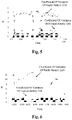
- Fig. 5 an exemplary simulation result of the coefficient of variation of the battery cells of the battery pack in the embodiment of the present application may be shown in Fig. 5 .
- the coefficient of variation B of a faulty battery cell fluctuates between 4-6 most of the time, while the coefficient of variation B of a normal battery cell basically does not exceed 2, i.e., the coefficient of variation B of the normal battery cell is fluctuates between 0 and 2.
- Fig. 6 an exemplary simulation result of the coefficient of variation of the battery cells of the battery pack in the embodiment of the present application may be shown in Fig. 6 .
- the coefficient of variation B of a faulty battery cell fluctuates between 10-12 in most cases, while the maximum value of the coefficient of variation B of a normal battery cell may be slightly greater than 4, i.e., the coefficient of variation B of the normal battery cell fluctuates basically between 0 and 4.
- both the preset parameter threshold under a condition that the quantity of battery cells in the battery pack is 192 and the preset parameter threshold under a condition that the number of battery cells in the battery pack is 30 are 10
- the preset parameter threshold under a condition that the number of battery cells in the battery pack is 30 are 10
- the first parameter can be calculated according to the electrical signal values at the multiple times of the target battery cell. For m battery cells of the same battery pack, a change rate of an electrical signal of a faulty battery cell in which an internal short-circuit fault occurs will differ from a change rate of an electrical signal of a normal battery cell, and correspondingly a degree of fluctuation of the electrical signal of the faulty battery cell will also differ from that of the normal battery cell.
- the first parameter can characterize the degree of fluctuation of the electrical signal
- the first parameter of the faulty battery cell is also different from that of the normal battery cell.
- the degree of dispersion between the first parameter of the faulty battery cell and the first parameters of other battery cells will be greater than that of a normal battery cell. Therefore, the second parameter characterizing the degree of dispersion between the first parameter of each battery cell and the first parameters of the other battery cells is used. Since the second parameter has a positive correlation with the degree of dispersion, a battery cell in which an internal short-circuit occurs can be detected accurately, when the second parameter of the battery cell is greater than the preset parameter threshold.
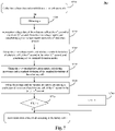
- Fig. 7 is a schematic flowchart of an exemplary method for detecting an internal short-circuit fault of a battery cell provided by an embodiment of the present application.
- the method 700 for detecting the internal short-circuit fault of the battery cell may include S710 to S790.
- S710 Voltage data are collected and a t ⁇ m voltage matrix is established. Particularly, when the battery pack is in the process of charging, voltage data of all the m battery cells of the battery pack within a total of t seconds are collected, and the t ⁇ m voltage matrix is established according to the voltage data of the m battery cells at the t seconds.
- the t ⁇ m voltage matrix is specifically expressed as: V 1,1 ⁇ V 1 , m ⁇ ⁇ ⁇ V t , 1 ⁇ V t , m
- the i th row data in the t ⁇ m voltage matrix represent voltage data of each of the m battery cells at the i th second
- the j th column data in the voltage matrix represent voltage data of the j th battery cell within the t seconds.
- t in this embodiment is equal to 96 seconds.
- the p ⁇ m voltage matrix is specifically expressed as: V n , 1 ⁇ V n , m ⁇ ⁇ ⁇ V n + p ⁇ 1,1 ⁇ V n + p ⁇ 1 , m
- a standard deviation ⁇ of each battery cell at the n th second to the ( n + p -1) th second is calculated using the p ⁇ m voltage matrix of the previous step, and a 1 ⁇ m standard deviation matrix is generated.
- one standard deviation ⁇ may be calculated from p voltage data in each column of the p ⁇ m voltage matrix.
- the standard deviations of the m battery cells may be expressed as the following 1 ⁇ m standard deviation matrix: ⁇ 1,1 ⁇ ⁇ 1 , m .
- S750 An average ⁇ mean and a standard deviation ⁇ ⁇ of the standard deviations of the m battery cells are calculated using the 1 ⁇ m standard deviation matrix of the previous step.
- the present application uses the first n seconds since the internal short-circuit begins to occur, for example, the voltage data of the first 96 seconds, to determine whether internal short-circuit fault occurs in a battery cell, and is thus able to identify a faulty battery cell in time in an early stage of the internal short circuit fault, so as to avoid occurrence of the thermal runaway to the greatest extent, and ensure the safety of the battery to the greatest extent.
- Fig. 8 is a schematic structural diagram of the apparatus for detecting the internal short-circuit fault of the battery cell provided by the embodiment of the present application.
- the apparatus 800 for detecting the internal short-circuit fault of the battery cell includes a data obtaining module 810, a first calculation module 820, a second calculation module 830 and fault detection module 840.
- the data obtaining module 810 is configured to obtain electrical signal values at multiple times for each of m battery cells of a battery pack, when the battery pack is in a preset condition.
- the preset condition comprises that a current detection is an n th detection of an internal short-circuit fault of a battery cell, and m and n are positive integers.
- the preset condition includes that it is currently in the nth detection process for the internal short-circuit fault of the battery, and m and n are positive integers.
- the first calculation module 820 is configured to calculate, for a target battery cell of the battery pack, a first parameter of the target battery cell using the electrical signal values at the multiple times of the target battery cell.
- the first parameter is used to characterize a degree of fluctuation of the electrical signal values of the target battery cell.
- the second calculation module 830 is configured to calculate, for the target battery cell of the battery pack, a second parameter that characterizes a degree of dispersion between the first parameter of the target battery cell and first parameters of other battery cells.
- the second parameter has a positive correlation with the degree of dispersion, and the other cells are battery cells of the m battery cells other than the target battery cell.
- the fault detection module 840 is configured to determine, for the target battery cell of the battery pack, that an internal short-circuit fault occurs in the target battery cell, under a condition that the second parameter is greater than a preset parameter threshold.
- the preset condition when n is an integer greater than 1, the preset condition further includes that the second parameter of the target battery cell is greater than the preset parameter threshold, for each of first n-1 detections of the internal short-circuit fault of the battery cell.
- the preset parameter threshold has a positive correlation with a quantity of the m battery cells.
- the first parameter of the target battery cell is a standard deviation of the electrical signal values at the multiple times of the target battery cell.
- the second parameter is a coefficient of variation.
- the second calculation module 830 may specifically include a first calculation unit and a second calculation unit.
- the first calculation unit is configured to calculate target standard deviation characterizing a degree of dispersion of first parameters of the m battery cells, and calculate an average of the first parameters of the m battery cells.
- the second calculation unit is configured to calculate a ratio of a target difference to the target standard deviation, and determine the ratio as the coefficient of variation of the target battery cell.
- the target difference is a difference between the first parameter of the target battery cell and the average.
- the first parameter can be calculated according to the electrical signal values at the multiple times of the target battery cell. For m battery cells of the same battery pack, a change rate of an electrical signal of a faulty battery cell in which an internal short-circuit fault occurs will differ from a change rate of an electrical signal of a normal battery cell, and correspondingly a degree of fluctuation of the electrical signal of the faulty battery cell will also differ from that of the normal battery cell.
- the first parameter can characterize the degree of fluctuation of the electrical signal
- the first parameter of the faulty battery cell is also different from that of the normal battery cell.
- the degree of dispersion between the first parameter of the faulty battery cell and the first parameters of other battery cells will be greater than that of a normal battery cell. Therefore, the second parameter characterizing the degree of dispersion between the first parameter of each battery cell and the first parameters of the other battery cells is used. Since the second parameter has a positive correlation with the degree of dispersion, a battery cell in which an internal short-circuit occurs can be detected accurately, when the second parameter of the battery cell is greater than the preset parameter threshold.
- Fig. 9 shows a schematic hardware structure diagram of a device for detecting an internal short-circuit fault of a battery cell provided by an embodiment of the present application.
- the device for detecting the internal short-circuit fault of the battery cell may include a processor 901 and a memory 902 having computer program instructions stored thereon.
- the above-mentioned processor 901 may include a central processing unit (Central Processing Unit, CPU), or an application specific integrated circuit (Application Specific Integrated Circuit, ASIC), or one or more integrated circuits that may be configured to implement of the embodiments of the present application.
- CPU Central Processing Unit
- ASIC Application Specific Integrated Circuit
- the memory 902 may include a mass memory for data or instructions.
- the memory 902 may include a hard disk drive (Hard Disk Drive, HDD), a floppy disk drive, a flash memory, an optical disk, a magneto-optical disk, a magnetic tape or a universal serial bus (Universal Serial Bus, USB) drive, or a combination of two or more of them.
- the memory 902 may include removable or non-removable (or fixed) media, or the memory 902 may be a non-volatile solid-state memory.
- the memory 902 may be internal or external to the device for detecting the internal short-circuit fault of the battery cell.
- the memory 902 may be a read only memory (Read Only Memory, ROM).
- ROM Read Only Memory
- the ROM may be a mask-programmed ROM, a programmable ROM (PROM), an erasable PROM (EPROM), an electrically erasable PROM (EEPROM), an electrically rewritable ROM (EAROM) or flash memory, or a combination of two or more of them.
- the memory 902 may include a read-only memory (ROM), a random access memory (RAM), a magnetic disk storage media device, an optical storage media devices, a flash memory device, an electrical, optical, or other physical/tangible memory storage device. Therefore, generally, the memory may include one or more tangible (non-transitory) computer-readable storage media (e.g., memory devices) encoded with software including computer-executable instructions, and when the software is executed (e.g., by one or more processors), it is operable to perform operations described with reference to the method according to an aspect of the present disclosure.
- the processor 901 reads and executes the computer program instructions stored in the memory 902, to implement the methods in the embodiments shown in Fig. 1 to Fig. 7 , and achieve corresponding technical effects achieved when the methods/steps of the embodiments shown in Fig. 1 to Fig. 7 are executed, which will not be repeated here, for concision of the description.
- the device for detecting the internal short-circuit fault of the battery cell may further include a communication interface 903 and a bus 910. As shown in Fig. 9 , the processor 901, the memory 902, and the communication interface 903 are connected and communicate mutually through the bus 910.
- the communication interface 903 is mainly used to implement communications between various modules, apparatuses, units and/or devices in the embodiments of the present application.
- the bus 910 may include hardware, software, or both, and couple components of an online data flow accounting device to each other.
- the bus may include an accelerated graphics port (Accelerated Graphics Port, AGP) or other graphics bus, an enhanced industry standard architecture (Extended Industry Standard Architecture, EISA) bus, a front side bus (Front Side Bus, FSB), a hyper transport (Hyper Transport, HT) interconnection, an industry standard architecture (Industry Standard Architecture, ISA) bus, an unlimited bandwidth interconnection, a low pin count (LPC) bus, a memory bus, a microchannel architecture (MCA) bus, a peripheral component interconnection PCI bus, a PCI-Express (PCI-X) bus, a Serial Advanced Technology Attachment (SATA) bus, a Video Electronics Standards Association Local (VLB) bus or other suitable bus or a combination of two or more of them.
- the bus 910 may include one or more buses.
- the device for detecting the internal short-circuit fault of the battery cell can execute the method for detecting the internal short-circuit fault of the battery cell in the embodiment of the present application, so as to realize the method and apparatus for detecting the internal short-circuit fault of the battery cell described in conjunction with Fig. 1 to Fig. 8 .
- an embodiment of the present application may provide a computer storage medium to implement the method.
- the computer storage medium has computer program instructions stored thereon. When the computer program instructions are executed by the processor, any method for detecting the internal short-circuit fault of the battery cell in the aforementioned embodiment can be implemented.
- machine-readable media may include electronic circuits, semiconductor memory devices, ROMs, flash memories, erasable ROMs (EROMs), floppy disks, CD-ROMs, optical disks, hard disks, fiber optic media, radio frequency (Radio Frequency, RF) links, and so on.
- the code segments can be downloaded via a computer network such as the Internet, an intranet, etc.
- the exemplary embodiments described in the present application describe some methods or systems based on a series of steps and apparatuses.
- the present application is not limited to the order of the above steps. That is to say, the steps may be executed in the order described in the embodiments or in an order different from that in the embodiments, or several steps may be executed simultaneously.
- Such processor may be, but is not limited to, a general-purpose processor, a dedicated processor, a special application processor, or a field programmable logic circuit. It can also be understood that each block in the block diagrams and/or flowcharts and a combination of the blocks in the block diagrams and/or flowcharts may be implemented by dedicated hardware that performs specified functions or actions, or may be implemented by a combination of the dedicated hardware and the computer instructions.
Landscapes
- Physics & Mathematics (AREA)
- General Physics & Mathematics (AREA)
- Engineering & Computer Science (AREA)
- Manufacturing & Machinery (AREA)
- Chemical & Material Sciences (AREA)
- Chemical Kinetics & Catalysis (AREA)
- Electrochemistry (AREA)
- General Chemical & Material Sciences (AREA)
- Tests Of Electric Status Of Batteries (AREA)
- Secondary Cells (AREA)
- Testing Of Short-Circuits, Discontinuities, Leakage, Or Incorrect Line Connections (AREA)
- Testing Electric Properties And Detecting Electric Faults (AREA)
Claims (10)
- Computerimplementiertes Verfahren (300) zum Erfassen eines internen Kurzschlussfehlers einer Batteriezelle, dadurch gekennzeichnet, dass das umfasst:mehrmaliges Erhalten (310) von elektrischen Signalwerten für jede von m Batteriezellen eines Batteriepakets, wenn das Batteriepaket in einem voreingestellten Zustand ist, wobei das Vorhandensein des internen Kurzschlussfehlers der Batteriezelle mehrere Male erfasst wird und die die voreingestellte Bedingung umfasst, dass eine aktuell auftretende Erkennung eine n-te Erkennung ist und m und n positive ganze Zahlen sind;Durchführen der folgenden Schritte für eine Zielbatteriezelle des Batteriepacks:Berechnen (320) eines ersten Parameters der Zielbatteriezelle unter Verwendung der elektrischen Signalwerte zu den mehreren Zeiten der Zielbatteriezelle, wobei der erste Parameter verwendet wird, um einen Schwankungsgrad der elektrischen Signalwerte der Zielbatteriezelle zu charakterisieren;Berechnen (330) eines zweiten Parameters, der einen Streuungsgrad zwischen dem ersten Parameter der Zielbatteriezelle und ersten Parametern anderer Batteriezellen charakterisiert, wobei die anderen Zellen Batteriezellen der m Batteriezellen außer der Zielbatteriezelle sind, und der zweite Parameter eine positive Korrelation mit dem Dispersionsgrad aufweist; undBestimmen (340), dass ein interner Kurzschlussfehler in der Zielbatteriezelle auftritt, unter einer Bedingung, dass der zweite Parameter größer als ein voreingestellter Parameterschwellenwert ist.
- Computerimplementiertes Verfahren (300) zum Erfassen des internen Kurzschlussfehlers der Batteriezelle nach Anspruch 1, wobei, wenn n eine ganze Zahl größer als 1 ist, die voreingestellte Bedingung ferner Folgendes umfasst:
dass der zweite Parameter der Zielbatteriezelle größer als der voreingestellte Parameterschwellenwert für jede der ersten n-1 Erfassungen des internen Kurzschlussfehlers der Batteriezelle ist. - Computerimplementiertes Verfahren (300) zum Erfassen des internen Kurzschlussfehlers der Batteriezelle nach Anspruch 1 oder Anspruch 2, wobei der voreingestellte Parameterschwellenwert eine positive Korrelation mit einer Menge der m Batteriezellen aufweist.
- Computerimplementiertes Verfahren (300) zum Erfassen des internen Kurzschlussfehlers der Batteriezelle nach einem der Ansprüche 1 bis 3, wobei der erste Parameter der Zielbatteriezelle eine Standardabweichung der elektrischen Signalwerte zu mehreren Zeiten der Zielbatteriezelle ist.
- Computerimplementiertes Verfahren (300) zum Erfassen des internen Kurzschlussfehlers der Batteriezelle nach Anspruch 1 oder Anspruch 4, wobei der zweite Parameter ein Variationskoeffizient ist,
das Berechnen (330) des zweiten Parameters, der den Streuungsgrad zwischen dem ersten Parameter der Zielbatteriezelle und dem ersten Parameter anderer Batteriezellen charakterisiert, umfasst:Berechnen (331) einer Zielstandardabweichung, die einen Streuungsgrad von ersten Parametern der m Batteriezellen charakterisiert, und Berechnen eines Durchschnitts der ersten Parameter der m Batteriezellen; undBerechnen (332) eines Verhältnisses einer Zieldifferenz zu der Zielstandardabweichung und Bestimmen des Verhältnisses als Variationskoeffizient der Zielbatteriezelle, wobei die Zieldifferenz eine Differenz zwischen dem ersten Parameter der Zielbatteriezelle und dem Durchschnitt ist. - Vorrichtung (800) zum Erfassen eines internen Kurzschlussfehlers einer Batteriezelle, dadurch gekennzeichnet, dass die Vorrichtung umfasst:ein Datenbeschaffungsmodul (810), das so konfiguriert ist, dass es mehrfach elektrische Signalwerte für jede von m Batteriezellen eines Batteriepakets erhält, wenn das Batteriepaket in einem voreingestellten Zustand ist, wobei das Vorhandensein des internen Kurzschlussfehlers der Batteriezelle mehrere Male erfasst wird und die die voreingestellte Bedingung umfasst, dass eine aktuell auftretende Erkennung eine n-te Erkennung ist und m und n positive ganze Zahlen sind;ein erstes Berechnungsmodul (820), das dazu konfiguriert ist, für eine Zielbatteriezelle des Batteriepacks eines ersten Parameters der Zielbatteriezelle unter Verwendung der elektrischen Signalwerte zu den mehreren Zeiten der Zielbatteriezelle zu berechnen, wobei der erste Parameter verwendet wird, um einen Schwankungsgrad der elektrischen Signalwerte der Zielbatteriezelle zu charakterisieren;ein zweites Berechnungsmodul (830), das dazu konfiguriert ist, für die Zielbatteriezelle des Batteriepakets einen zweiten Parameter zu berechnen, der einen Streuungsgrad zwischen dem ersten Parameter der Zielbatteriezelle und ersten Parametern anderer Batteriezellen charakterisiert, wobei das der zweite Parameter eine positive Korrelation mit dem Streuungsgrad aufweist, und die anderen Zellen Batteriezellen der m Batteriezellen außer der Zielbatteriezelle sind; undein Fehlererkennungsmodul (840), das konfiguriert ist, um für die Zielbatteriezelle des Batteriepacks zu bestimmen, unter einer Bedingung, dass der zweite Parameter größer als ein voreingestellter Parameterschwellenwert ist.
- Vorrichtung (800) zum Erfassen des internen Kurzschlussfehlers der Batteriezelle nach Anspruch 6, wobei, wenn n eine ganze Zahl größer als 1 ist, die voreingestellte Bedingung ferner Folgendes umfasst:
dass der zweite Parameter der Zielbatteriezelle größer als der voreingestellte Parameterschwellenwert für jede der ersten n-1 Erfassungen des internen Kurzschlussfehlers der Batteriezellen ist. - Vorrichtung (800) zum Erfassen des internen Kurzschlussfehlers der Batteriezelle nach Anspruch 6 oder Anspruch 7, wobei der voreingestellte Parameterschwellenwert eine positive Korrelation mit einer Menge der m Batteriezellen aufweist.
- Vorrichtung (900) zum Erfassen eines internen Kurzschlussfehlers einer Batteriezelle, umfassend:einen Speicher (902), der zum Speichern von Programmen konfiguriert ist; undeinen Prozessor (901), der dazu konfiguriert ist, die in dem Speicher (902) gespeicherten Programme auszuführen, um das Verfahren (300) zum Erfassen des internen Kurzschlussfehlers der Batteriezelle nach einem der Ansprüche 1 bis 5 durchzuführen.
- Computerspeichermedium mit darauf gespeicherten Computerprogrammanweisungen, die bei Ausführung durch einen Prozessor (901) bewirken, dass das Verfahren (300) zum Erfassen des internen Kurzschlussfehlers der Batteriezelle nach einem der Ansprüche 1 bis 5 implementiert wird.
Applications Claiming Priority (2)
| Application Number | Priority Date | Filing Date | Title |
|---|---|---|---|
| CN202010616755.XA CN113866669B (zh) | 2020-06-30 | 2020-06-30 | 电芯内部短路故障的检测方法、装置、设备和介质 |
| PCT/CN2021/081241 WO2022001197A1 (zh) | 2020-06-30 | 2021-03-17 | 电芯内部短路故障的检测方法、装置、设备和介质 |
Publications (3)
| Publication Number | Publication Date |
|---|---|
| EP3961235A1 EP3961235A1 (de) | 2022-03-02 |
| EP3961235A4 EP3961235A4 (de) | 2022-09-07 |
| EP3961235B1 true EP3961235B1 (de) | 2023-01-11 |
Family
ID=78981501
Family Applications (1)
| Application Number | Title | Priority Date | Filing Date |
|---|---|---|---|
| EP21800970.2A Active EP3961235B1 (de) | 2020-06-30 | 2021-03-17 | Verfahren, gerät, vorrichtung und medium zur erkennung eines internen kurzschlussfehlers einer batteriezelle |
Country Status (7)
| Country | Link |
|---|---|
| US (1) | US11614494B2 (de) |
| EP (1) | EP3961235B1 (de) |
| JP (1) | JP7344393B2 (de) |
| KR (1) | KR102679929B1 (de) |
| CN (1) | CN113866669B (de) |
| HU (1) | HUE061176T2 (de) |
| WO (1) | WO2022001197A1 (de) |
Families Citing this family (12)
| Publication number | Priority date | Publication date | Assignee | Title |
|---|---|---|---|---|
| US12241943B2 (en) * | 2021-07-14 | 2025-03-04 | GM Global Technology Operations LLC | Method for early detection of an internal short in a battery pack |
| KR20230032724A (ko) * | 2021-08-31 | 2023-03-07 | 주식회사 엘지에너지솔루션 | Tdr을 이용한 전지셀의 내부 결함 검출장치 및 방법 |
| CN115184808B (zh) * | 2022-07-05 | 2024-06-18 | 东莞新能安科技有限公司 | 电池热失控风险检测方法、装置、设备及计算机存储介质 |
| CN115144765A (zh) * | 2022-07-05 | 2022-10-04 | 东莞新能安科技有限公司 | 电池内短路故障检测方法及装置 |
| CN115042628B (zh) * | 2022-07-27 | 2025-04-08 | 浙江极氪智能科技有限公司 | 车辆热失控预警方法、装置、电子设备及可读存储介质 |
| CN115664004A (zh) * | 2022-10-18 | 2023-01-31 | 阳光电源股份有限公司 | 储能系统安全监测方法、装置、设备及存储介质 |
| CN116400243A (zh) * | 2023-03-22 | 2023-07-07 | 上海玫克生储能科技有限公司 | 一种检测电芯异常状态的方法和装置 |
| CN116559688A (zh) * | 2023-05-19 | 2023-08-08 | 华能澜沧江水电股份有限公司 | 电池故障的检测方法、装置、设备及存储介质 |
| CN116794542B (zh) * | 2023-06-06 | 2024-01-16 | 东莞市腾威动力新能源有限公司 | 一种储能电池短路检测和保护的方法及系统 |
| CN117007971B (zh) * | 2023-07-05 | 2024-10-15 | 湖南行必达网联科技有限公司 | 电池故障诊断方法、装置及系统 |
| CN119224627B (zh) * | 2024-12-02 | 2025-04-04 | 宁德时代新能源科技股份有限公司 | 故障检测方法、电池管理系统以及电池包 |
| CN120103175B (zh) * | 2025-05-09 | 2025-09-09 | 宁德时代新能源科技股份有限公司 | 电池内短路检测方法、装置、终端及计算机可读存储介质 |
Family Cites Families (16)
| Publication number | Priority date | Publication date | Assignee | Title |
|---|---|---|---|---|
| JP3975798B2 (ja) * | 2002-03-25 | 2007-09-12 | トヨタ自動車株式会社 | 組電池の異常検出装置および異常検出方法 |
| JP5422810B2 (ja) | 2009-03-26 | 2014-02-19 | 株式会社Nttファシリティーズ | 予備電源システム及び予備電源システム保護方法 |
| CN103163464B (zh) * | 2011-12-14 | 2016-01-20 | 微宏动力系统(湖州)有限公司 | 电池包中电芯的检测方法 |
| CN103545564B (zh) | 2012-07-16 | 2015-12-09 | 联想(北京)有限公司 | 充电电池单元及其缺陷检测方法 |
| CN104617330B (zh) | 2015-01-19 | 2017-01-25 | 清华大学 | 电池微短路的识别方法 |
| CN106932722A (zh) * | 2015-12-30 | 2017-07-07 | 华为技术有限公司 | 一种动力电池的内短路检测方法及装置 |
| CN107923949B (zh) | 2016-01-28 | 2021-07-09 | 松下知识产权经营株式会社 | 管理装置以及蓄电系统 |
| JP6986707B2 (ja) * | 2016-08-30 | 2021-12-22 | パナソニックIpマネジメント株式会社 | 管理装置、及び蓄電システム |
| WO2018131427A1 (ja) | 2017-01-16 | 2018-07-19 | パナソニックIpマネジメント株式会社 | 検査装置、検査方法、検査プログラム、管理装置、及び蓄電システム |
| US10788536B2 (en) * | 2017-05-11 | 2020-09-29 | Texas Instruments Incorporated | System and apparatus for battery internal short current detection under arbitrary load conditions |
| CN107831443A (zh) * | 2017-10-20 | 2018-03-23 | 开沃新能源汽车集团有限公司 | 基于相关系数的电池系统短路故障诊断方法 |
| CN110764014A (zh) * | 2018-07-26 | 2020-02-07 | 东莞新能德科技有限公司 | 电池内短路的检测方法、装置、终端及可读存储介质 |
| CN109709485A (zh) * | 2019-02-01 | 2019-05-03 | 北京长城华冠汽车科技股份有限公司 | 动力电池的故障检测方法、装置、介质和电子设备 |
| CN110376530B (zh) * | 2019-08-08 | 2020-06-30 | 清华大学 | 电池内短路检测装置及方法 |
| CN110687457B (zh) * | 2019-11-13 | 2021-12-03 | 东软睿驰汽车技术(沈阳)有限公司 | 一种电池包异常的检测方法、装置、存储介质及电子设备 |
| KR20210080069A (ko) | 2019-12-20 | 2021-06-30 | 주식회사 엘지에너지솔루션 | 배터리 진단 장치 및 방법 |
-
2020
- 2020-06-30 CN CN202010616755.XA patent/CN113866669B/zh active Active
-
2021
- 2021-03-17 WO PCT/CN2021/081241 patent/WO2022001197A1/zh not_active Ceased
- 2021-03-17 JP JP2022542954A patent/JP7344393B2/ja active Active
- 2021-03-17 EP EP21800970.2A patent/EP3961235B1/de active Active
- 2021-03-17 HU HUE21800970A patent/HUE061176T2/hu unknown
- 2021-03-17 KR KR1020227023944A patent/KR102679929B1/ko active Active
- 2021-12-31 US US17/566,694 patent/US11614494B2/en active Active
Also Published As
| Publication number | Publication date |
|---|---|
| JP7344393B2 (ja) | 2023-09-13 |
| EP3961235A4 (de) | 2022-09-07 |
| US11614494B2 (en) | 2023-03-28 |
| KR20220114038A (ko) | 2022-08-17 |
| JP2023503185A (ja) | 2023-01-26 |
| US20220196748A1 (en) | 2022-06-23 |
| CN113866669B (zh) | 2023-09-15 |
| HUE061176T2 (hu) | 2023-05-28 |
| KR102679929B1 (ko) | 2024-07-02 |
| WO2022001197A1 (zh) | 2022-01-06 |
| EP3961235A1 (de) | 2022-03-02 |
| CN113866669A (zh) | 2021-12-31 |
Similar Documents
| Publication | Publication Date | Title |
|---|---|---|
| EP3961235B1 (de) | Verfahren, gerät, vorrichtung und medium zur erkennung eines internen kurzschlussfehlers einer batteriezelle | |
| EP4113142B1 (de) | Isolationsüberwachungsverfahren, system und vorrichtung für eine strombatterie | |
| EP3919319A1 (de) | Batterieladesteuerungsverfahren und -vorrichtung, batterieverwaltungssystem und medium | |
| CN113687234B (zh) | 电池异常识别方法、装置、设备、介质及程序产品 | |
| US20240110987A1 (en) | Battery detection method and battery detection device | |
| EP4206707B1 (de) | Vorrichtung und verfahren zur batterieüberwachung | |
| CN118613986A (zh) | 快速充电控制装置和方法 | |
| CN112698234A (zh) | 电池包绝缘异常原因分析方法、装置和计算机设备 | |
| EP4350374A1 (de) | Vorrichtung und verfahren zur schätzung des batteriezustands | |
| CN116299016A (zh) | 一种电池的析锂现象检测方法、装置、设备及存储介质 | |
| JP7485043B2 (ja) | 電源装置および電池の不具合検出方法 | |
| CN116788049B (zh) | 碰撞处置方法、装置、设备、存储介质及用电装置 | |
| CN118534048A (zh) | 一种基于气体传感的锂离子电池析锂检测方法 | |
| WO2024131619A1 (zh) | 电池析锂状态检测方法、装置、设备、存储介质及车辆 | |
| CN118169578A (zh) | 新能源汽车动力电池故障诊断方法及故障电池定位方法 | |
| CN118801512A (zh) | 一种充电安全防护装置、方法及充电系统 | |
| KR20240138387A (ko) | 배터리 진단장치 및 방법 | |
| CN116626492A (zh) | 电池故障诊断方法、装置及车辆 | |
| EP4549966A1 (de) | Verfahren und vorrichtung zur erkennung von li-plattierung in einer lithiumbatterie | |
| CN115166538B (zh) | 充电检测方法、装置、设备及产品 | |
| CN116466247B (zh) | 一种电池组的绝缘监测方法及电池组的绝缘监测装置 | |
| CN118219834A (zh) | 参数的确定方法、装置、电子设备、存储介质及产品 | |
| EP4053968B1 (de) | Vorrichtung und verfahren zur erkennung von schäden an einem batteriepackgehäuse | |
| KR20250094270A (ko) | 배터리 진단 장치 및 그의 동작 방법 | |
| CN121477023A (zh) | 一种电芯异常检测方法、系统、装置以及设备 |
Legal Events
| Date | Code | Title | Description |
|---|---|---|---|
| STAA | Information on the status of an ep patent application or granted ep patent |
Free format text: STATUS: UNKNOWN |
|
| STAA | Information on the status of an ep patent application or granted ep patent |
Free format text: STATUS: THE INTERNATIONAL PUBLICATION HAS BEEN MADE |
|
| PUAI | Public reference made under article 153(3) epc to a published international application that has entered the european phase |
Free format text: ORIGINAL CODE: 0009012 |
|
| STAA | Information on the status of an ep patent application or granted ep patent |
Free format text: STATUS: REQUEST FOR EXAMINATION WAS MADE |
|
| 17P | Request for examination filed |
Effective date: 20211122 |
|
| AK | Designated contracting states |
Kind code of ref document: A1 Designated state(s): AL AT BE BG CH CY CZ DE DK EE ES FI FR GB GR HR HU IE IS IT LI LT LU LV MC MK MT NL NO PL PT RO RS SE SI SK SM TR |
|
| A4 | Supplementary search report drawn up and despatched |
Effective date: 20220805 |
|
| RIC1 | Information provided on ipc code assigned before grant |
Ipc: G01R 31/396 20190101ALI20220801BHEP Ipc: H01M 10/48 20060101ALI20220801BHEP Ipc: G01R 31/392 20190101ALI20220801BHEP Ipc: G01R 31/52 20200101AFI20220801BHEP |
|
| GRAP | Despatch of communication of intention to grant a patent |
Free format text: ORIGINAL CODE: EPIDOSNIGR1 |
|
| STAA | Information on the status of an ep patent application or granted ep patent |
Free format text: STATUS: GRANT OF PATENT IS INTENDED |
|
| GRAS | Grant fee paid |
Free format text: ORIGINAL CODE: EPIDOSNIGR3 |
|
| GRAA | (expected) grant |
Free format text: ORIGINAL CODE: 0009210 |
|
| STAA | Information on the status of an ep patent application or granted ep patent |
Free format text: STATUS: THE PATENT HAS BEEN GRANTED |
|
| INTG | Intention to grant announced |
Effective date: 20221115 |
|
| AK | Designated contracting states |
Kind code of ref document: B1 Designated state(s): AL AT BE BG CH CY CZ DE DK EE ES FI FR GB GR HR HU IE IS IT LI LT LU LV MC MK MT NL NO PL PT RO RS SE SI SK SM TR |
|
| DAV | Request for validation of the european patent (deleted) | ||
| DAX | Request for extension of the european patent (deleted) | ||
| REG | Reference to a national code |
Ref country code: GB Ref legal event code: FG4D |
|
| REG | Reference to a national code |
Ref country code: CH Ref legal event code: EP |
|
| REG | Reference to a national code |
Ref country code: DE Ref legal event code: R096 Ref document number: 602021001227 Country of ref document: DE |
|
| REG | Reference to a national code |
Ref country code: IE Ref legal event code: FG4D |
|
| REG | Reference to a national code |
Ref country code: AT Ref legal event code: REF Ref document number: 1543729 Country of ref document: AT Kind code of ref document: T Effective date: 20230215 |
|
| REG | Reference to a national code |
Ref country code: NO Ref legal event code: T2 Effective date: 20230111 |
|
| REG | Reference to a national code |
Ref country code: LT Ref legal event code: MG9D |
|
| REG | Reference to a national code |
Ref country code: NL Ref legal event code: MP Effective date: 20230111 |
|
| REG | Reference to a national code |
Ref country code: HU Ref legal event code: AG4A Ref document number: E061176 Country of ref document: HU |
|
| REG | Reference to a national code |
Ref country code: AT Ref legal event code: MK05 Ref document number: 1543729 Country of ref document: AT Kind code of ref document: T Effective date: 20230111 |
|
| P01 | Opt-out of the competence of the unified patent court (upc) registered |
Effective date: 20230516 |
|
| PG25 | Lapsed in a contracting state [announced via postgrant information from national office to epo] |
Ref country code: NL Free format text: LAPSE BECAUSE OF FAILURE TO SUBMIT A TRANSLATION OF THE DESCRIPTION OR TO PAY THE FEE WITHIN THE PRESCRIBED TIME-LIMIT Effective date: 20230111 |
|
| PG25 | Lapsed in a contracting state [announced via postgrant information from national office to epo] |
Ref country code: RS Free format text: LAPSE BECAUSE OF FAILURE TO SUBMIT A TRANSLATION OF THE DESCRIPTION OR TO PAY THE FEE WITHIN THE PRESCRIBED TIME-LIMIT Effective date: 20230111 Ref country code: PT Free format text: LAPSE BECAUSE OF FAILURE TO SUBMIT A TRANSLATION OF THE DESCRIPTION OR TO PAY THE FEE WITHIN THE PRESCRIBED TIME-LIMIT Effective date: 20230511 Ref country code: LV Free format text: LAPSE BECAUSE OF FAILURE TO SUBMIT A TRANSLATION OF THE DESCRIPTION OR TO PAY THE FEE WITHIN THE PRESCRIBED TIME-LIMIT Effective date: 20230111 Ref country code: LT Free format text: LAPSE BECAUSE OF FAILURE TO SUBMIT A TRANSLATION OF THE DESCRIPTION OR TO PAY THE FEE WITHIN THE PRESCRIBED TIME-LIMIT Effective date: 20230111 Ref country code: HR Free format text: LAPSE BECAUSE OF FAILURE TO SUBMIT A TRANSLATION OF THE DESCRIPTION OR TO PAY THE FEE WITHIN THE PRESCRIBED TIME-LIMIT Effective date: 20230111 Ref country code: ES Free format text: LAPSE BECAUSE OF FAILURE TO SUBMIT A TRANSLATION OF THE DESCRIPTION OR TO PAY THE FEE WITHIN THE PRESCRIBED TIME-LIMIT Effective date: 20230111 Ref country code: AT Free format text: LAPSE BECAUSE OF FAILURE TO SUBMIT A TRANSLATION OF THE DESCRIPTION OR TO PAY THE FEE WITHIN THE PRESCRIBED TIME-LIMIT Effective date: 20230111 |
|
| PG25 | Lapsed in a contracting state [announced via postgrant information from national office to epo] |
Ref country code: SE Free format text: LAPSE BECAUSE OF FAILURE TO SUBMIT A TRANSLATION OF THE DESCRIPTION OR TO PAY THE FEE WITHIN THE PRESCRIBED TIME-LIMIT Effective date: 20230111 Ref country code: PL Free format text: LAPSE BECAUSE OF FAILURE TO SUBMIT A TRANSLATION OF THE DESCRIPTION OR TO PAY THE FEE WITHIN THE PRESCRIBED TIME-LIMIT Effective date: 20230111 Ref country code: IS Free format text: LAPSE BECAUSE OF FAILURE TO SUBMIT A TRANSLATION OF THE DESCRIPTION OR TO PAY THE FEE WITHIN THE PRESCRIBED TIME-LIMIT Effective date: 20230511 Ref country code: GR Free format text: LAPSE BECAUSE OF FAILURE TO SUBMIT A TRANSLATION OF THE DESCRIPTION OR TO PAY THE FEE WITHIN THE PRESCRIBED TIME-LIMIT Effective date: 20230412 Ref country code: FI Free format text: LAPSE BECAUSE OF FAILURE TO SUBMIT A TRANSLATION OF THE DESCRIPTION OR TO PAY THE FEE WITHIN THE PRESCRIBED TIME-LIMIT Effective date: 20230111 |
|
| REG | Reference to a national code |
Ref country code: DE Ref legal event code: R097 Ref document number: 602021001227 Country of ref document: DE |
|
| PG25 | Lapsed in a contracting state [announced via postgrant information from national office to epo] |
Ref country code: SM Free format text: LAPSE BECAUSE OF FAILURE TO SUBMIT A TRANSLATION OF THE DESCRIPTION OR TO PAY THE FEE WITHIN THE PRESCRIBED TIME-LIMIT Effective date: 20230111 Ref country code: RO Free format text: LAPSE BECAUSE OF FAILURE TO SUBMIT A TRANSLATION OF THE DESCRIPTION OR TO PAY THE FEE WITHIN THE PRESCRIBED TIME-LIMIT Effective date: 20230111 Ref country code: MC Free format text: LAPSE BECAUSE OF FAILURE TO SUBMIT A TRANSLATION OF THE DESCRIPTION OR TO PAY THE FEE WITHIN THE PRESCRIBED TIME-LIMIT Effective date: 20230111 Ref country code: EE Free format text: LAPSE BECAUSE OF FAILURE TO SUBMIT A TRANSLATION OF THE DESCRIPTION OR TO PAY THE FEE WITHIN THE PRESCRIBED TIME-LIMIT Effective date: 20230111 Ref country code: DK Free format text: LAPSE BECAUSE OF FAILURE TO SUBMIT A TRANSLATION OF THE DESCRIPTION OR TO PAY THE FEE WITHIN THE PRESCRIBED TIME-LIMIT Effective date: 20230111 Ref country code: CZ Free format text: LAPSE BECAUSE OF FAILURE TO SUBMIT A TRANSLATION OF THE DESCRIPTION OR TO PAY THE FEE WITHIN THE PRESCRIBED TIME-LIMIT Effective date: 20230111 |
|
| PLBE | No opposition filed within time limit |
Free format text: ORIGINAL CODE: 0009261 |
|
| STAA | Information on the status of an ep patent application or granted ep patent |
Free format text: STATUS: NO OPPOSITION FILED WITHIN TIME LIMIT |
|
| PG25 | Lapsed in a contracting state [announced via postgrant information from national office to epo] |
Ref country code: SK Free format text: LAPSE BECAUSE OF FAILURE TO SUBMIT A TRANSLATION OF THE DESCRIPTION OR TO PAY THE FEE WITHIN THE PRESCRIBED TIME-LIMIT Effective date: 20230111 |
|
| REG | Reference to a national code |
Ref country code: BE Ref legal event code: MM Effective date: 20230331 |
|
| 26N | No opposition filed |
Effective date: 20231012 |
|
| PG25 | Lapsed in a contracting state [announced via postgrant information from national office to epo] |
Ref country code: LU Free format text: LAPSE BECAUSE OF NON-PAYMENT OF DUE FEES Effective date: 20230317 |
|
| REG | Reference to a national code |
Ref country code: IE Ref legal event code: MM4A |
|
| PG25 | Lapsed in a contracting state [announced via postgrant information from national office to epo] |
Ref country code: SI Free format text: LAPSE BECAUSE OF FAILURE TO SUBMIT A TRANSLATION OF THE DESCRIPTION OR TO PAY THE FEE WITHIN THE PRESCRIBED TIME-LIMIT Effective date: 20230111 Ref country code: IE Free format text: LAPSE BECAUSE OF NON-PAYMENT OF DUE FEES Effective date: 20230317 |
|
| PG25 | Lapsed in a contracting state [announced via postgrant information from national office to epo] |
Ref country code: BE Free format text: LAPSE BECAUSE OF NON-PAYMENT OF DUE FEES Effective date: 20230331 |
|
| PG25 | Lapsed in a contracting state [announced via postgrant information from national office to epo] |
Ref country code: IT Free format text: LAPSE BECAUSE OF FAILURE TO SUBMIT A TRANSLATION OF THE DESCRIPTION OR TO PAY THE FEE WITHIN THE PRESCRIBED TIME-LIMIT Effective date: 20230111 |
|
| REG | Reference to a national code |
Ref country code: DE Ref legal event code: R081 Ref document number: 602021001227 Country of ref document: DE Owner name: CONTEMPORARY AMPEREX TECHNOLOGY (HONG KONG) LI, HK Free format text: FORMER OWNER: CONTEMPORARY AMPEREX TECHNOLOGY CO., LIMITED, NINGDE CITY, FUJIAN, CN |
|
| REG | Reference to a national code |
Ref country code: GB Ref legal event code: 732E Free format text: REGISTERED BETWEEN 20240822 AND 20240828 |
|
| REG | Reference to a national code |
Ref country code: HU Ref legal event code: GB9C Owner name: CONTEMPORARY AMPEREX TECHNOLOGY (HONG KONG) LIMITED, HK Free format text: FORMER OWNER(S): CONTEMPORARY AMPEREX TECHNOLOGY CO., LIMITED, CN Ref country code: HU Ref legal event code: FH1C Free format text: FORMER REPRESENTATIVE(S): SBGK SZABADALMI UEGYVIVOEI IRODA, HU Representative=s name: DANUBIA SZABADALMI ES JOGI IRODA KFT., HU |
|
| REG | Reference to a national code |
Ref country code: CH Ref legal event code: PL |
|
| PG25 | Lapsed in a contracting state [announced via postgrant information from national office to epo] |
Ref country code: BG Free format text: LAPSE BECAUSE OF FAILURE TO SUBMIT A TRANSLATION OF THE DESCRIPTION OR TO PAY THE FEE WITHIN THE PRESCRIBED TIME-LIMIT Effective date: 20230111 |
|
| PG25 | Lapsed in a contracting state [announced via postgrant information from national office to epo] |
Ref country code: BG Free format text: LAPSE BECAUSE OF FAILURE TO SUBMIT A TRANSLATION OF THE DESCRIPTION OR TO PAY THE FEE WITHIN THE PRESCRIBED TIME-LIMIT Effective date: 20230111 |
|
| PG25 | Lapsed in a contracting state [announced via postgrant information from national office to epo] |
Ref country code: CH Free format text: LAPSE BECAUSE OF NON-PAYMENT OF DUE FEES Effective date: 20240331 |
|
| PGFP | Annual fee paid to national office [announced via postgrant information from national office to epo] |
Ref country code: DE Payment date: 20241231 Year of fee payment: 5 |
|
| PGFP | Annual fee paid to national office [announced via postgrant information from national office to epo] |
Ref country code: HU Payment date: 20250205 Year of fee payment: 5 |
|
| PGFP | Annual fee paid to national office [announced via postgrant information from national office to epo] |
Ref country code: NO Payment date: 20250312 Year of fee payment: 5 |
|
| PGFP | Annual fee paid to national office [announced via postgrant information from national office to epo] |
Ref country code: GB Payment date: 20250102 Year of fee payment: 5 |
|
| PG25 | Lapsed in a contracting state [announced via postgrant information from national office to epo] |
Ref country code: CY Free format text: LAPSE BECAUSE OF FAILURE TO SUBMIT A TRANSLATION OF THE DESCRIPTION OR TO PAY THE FEE WITHIN THE PRESCRIBED TIME-LIMIT; INVALID AB INITIO Effective date: 20210317 |
|
| PG25 | Lapsed in a contracting state [announced via postgrant information from national office to epo] |
Ref country code: TR Free format text: LAPSE BECAUSE OF FAILURE TO SUBMIT A TRANSLATION OF THE DESCRIPTION OR TO PAY THE FEE WITHIN THE PRESCRIBED TIME-LIMIT Effective date: 20230111 |
|
| PGFP | Annual fee paid to national office [announced via postgrant information from national office to epo] |
Ref country code: FR Payment date: 20251231 Year of fee payment: 6 |