EP3961063A1 - Reduction gear and drive device using reduction gear - Google Patents
Reduction gear and drive device using reduction gear Download PDFInfo
- Publication number
- EP3961063A1 EP3961063A1 EP20795537.8A EP20795537A EP3961063A1 EP 3961063 A1 EP3961063 A1 EP 3961063A1 EP 20795537 A EP20795537 A EP 20795537A EP 3961063 A1 EP3961063 A1 EP 3961063A1
- Authority
- EP
- European Patent Office
- Prior art keywords
- block
- gear
- speed reduction
- input
- rotation
- Prior art date
- Legal status (The legal status is an assumption and is not a legal conclusion. Google has not performed a legal analysis and makes no representation as to the accuracy of the status listed.)
- Pending
Links
Images



Classifications
-
- F—MECHANICAL ENGINEERING; LIGHTING; HEATING; WEAPONS; BLASTING
- F16—ENGINEERING ELEMENTS AND UNITS; GENERAL MEASURES FOR PRODUCING AND MAINTAINING EFFECTIVE FUNCTIONING OF MACHINES OR INSTALLATIONS; THERMAL INSULATION IN GENERAL
- F16H—GEARING
- F16H1/00—Toothed gearings for conveying rotary motion
- F16H1/28—Toothed gearings for conveying rotary motion with gears having orbital motion
- F16H1/32—Toothed gearings for conveying rotary motion with gears having orbital motion in which the central axis of the gearing lies inside the periphery of an orbital gear
-
- F—MECHANICAL ENGINEERING; LIGHTING; HEATING; WEAPONS; BLASTING
- F16—ENGINEERING ELEMENTS AND UNITS; GENERAL MEASURES FOR PRODUCING AND MAINTAINING EFFECTIVE FUNCTIONING OF MACHINES OR INSTALLATIONS; THERMAL INSULATION IN GENERAL
- F16H—GEARING
- F16H57/00—General details of gearing
- F16H57/02—Gearboxes; Mounting gearing therein
- F16H57/021—Shaft support structures, e.g. partition walls, bearing eyes, casing walls or covers with bearings
- F16H57/022—Adjustment of gear shafts or bearings
-
- F—MECHANICAL ENGINEERING; LIGHTING; HEATING; WEAPONS; BLASTING
- F16—ENGINEERING ELEMENTS AND UNITS; GENERAL MEASURES FOR PRODUCING AND MAINTAINING EFFECTIVE FUNCTIONING OF MACHINES OR INSTALLATIONS; THERMAL INSULATION IN GENERAL
- F16H—GEARING
- F16H57/00—General details of gearing
- F16H57/02—Gearboxes; Mounting gearing therein
- F16H57/023—Mounting or installation of gears or shafts in the gearboxes, e.g. methods or means for assembly
-
- F—MECHANICAL ENGINEERING; LIGHTING; HEATING; WEAPONS; BLASTING
- F16—ENGINEERING ELEMENTS AND UNITS; GENERAL MEASURES FOR PRODUCING AND MAINTAINING EFFECTIVE FUNCTIONING OF MACHINES OR INSTALLATIONS; THERMAL INSULATION IN GENERAL
- F16H—GEARING
- F16H1/00—Toothed gearings for conveying rotary motion
- F16H1/28—Toothed gearings for conveying rotary motion with gears having orbital motion
- F16H1/32—Toothed gearings for conveying rotary motion with gears having orbital motion in which the central axis of the gearing lies inside the periphery of an orbital gear
- F16H2001/323—Toothed gearings for conveying rotary motion with gears having orbital motion in which the central axis of the gearing lies inside the periphery of an orbital gear comprising eccentric crankshafts driving or driven by a gearing
-
- F—MECHANICAL ENGINEERING; LIGHTING; HEATING; WEAPONS; BLASTING
- F16—ENGINEERING ELEMENTS AND UNITS; GENERAL MEASURES FOR PRODUCING AND MAINTAINING EFFECTIVE FUNCTIONING OF MACHINES OR INSTALLATIONS; THERMAL INSULATION IN GENERAL
- F16H—GEARING
- F16H1/00—Toothed gearings for conveying rotary motion
- F16H1/28—Toothed gearings for conveying rotary motion with gears having orbital motion
- F16H1/32—Toothed gearings for conveying rotary motion with gears having orbital motion in which the central axis of the gearing lies inside the periphery of an orbital gear
- F16H2001/327—Toothed gearings for conveying rotary motion with gears having orbital motion in which the central axis of the gearing lies inside the periphery of an orbital gear with the orbital gear having internal gear teeth
-
- F—MECHANICAL ENGINEERING; LIGHTING; HEATING; WEAPONS; BLASTING
- F16—ENGINEERING ELEMENTS AND UNITS; GENERAL MEASURES FOR PRODUCING AND MAINTAINING EFFECTIVE FUNCTIONING OF MACHINES OR INSTALLATIONS; THERMAL INSULATION IN GENERAL
- F16H—GEARING
- F16H57/00—General details of gearing
- F16H57/02—Gearboxes; Mounting gearing therein
- F16H2057/02086—Measures for reducing size of gearbox, e.g. for creating a more compact transmission casing
Definitions
- the present invention relates to a reducer and a drive device using the speed reducer.
- This application is based on and claims the benefit of priority from Japanese Patent Application Serial No. 2019-086559 (filed on April 26, 2019 ), the contents of which are hereby incorporated by reference in their entirety.
- Industrial robots, machine tools and the like may include a speed reducer to reduce the speed of rotation of a rotary drive source such as a motor (see, for example, Patent Literature 1).
- the speed reducer described in Patent Literature 1 has a main speed reduction unit that reduces a speed of rotation of an input side and transmits the rotation to an output side, and an upstream gear mechanism that reduces a speed of rotation of a rotary drive source such as a motor and transmits the rotation to the main speed reduction unit.
- the main speed reduction unit includes an outer cylinder block having a substantially circular cylindrical shape, a carrier block rotatably supported by the outer cylinder block, an input rotor (eccentric shaft) rotatably supported at a position radially offset from the rotation center of the carrier block, and a main speed reduction mechanism that reduces rotation of the input rotor and transmits the rotation to the carrier block.
- the outer cylinder block is fixed to an installation site such as a floor surface, and the carrier block is coupled to a rotary block such as a turntable.
- the main speed reduction mechanism includes a plurality of internal tooth pins on an inner circumference of the outer cylinder block and a pivot gear that pivots and revolves in the inside of the outer cylinder block.
- the pivot gear has a smaller number of external teeth than the number of internal tooth pins, and the external teeth are configured to engage with the plurality of internal tooth pins.
- the input rotor supported by the carrier block has a driven gear that receives an external rotational force and a crank-shaped eccentric portion. The eccentric portion is pivotally engaged with the pivot gear such that it rotates in phase with the pivot gear.
- the rotation of the input rotor rotates the pivot gear pivotally, and the revolving movement of the pivot gear is reduced at a predetermined reduction ratio while the external teeth of the pivot gear engage the internal tooth pins.
- the carrier block rotates at the same speed as the pivot gear.
- the gear mechanism provided in a front stage is supported rotatably on top of the carrier block, and includes an output gear that meshes with the driven gear of the input rotor and an intermediate gear that meshes with the output gear and an input gear of the rotary drive source.
- the intermediate gear is rotatably supported by a support shaft provided on and protruding from the carrier block.
- the gear mechanism in the front stage reduces the rotation to a reduction ratio corresponding to the ratio of the number of teeth between the output gear and input gear.
- Patent Literature 1 Publication of Japanese Patent No. 5231530
- the intermediate gear that is a part of the gear mechanism provided in a front stage is supported by the carrier block provided on the main speed reduction unit side. Therefore the carrier block needs to have an increased thickness (axial length) to accommodate the shaft that supports the intermediate gear in the carrier block. Therefore, it was difficult to realize the thinner main speed reducer unit in the speed reducer described in Patent Literature 1.
- the present invention provides a reducer in which a thinner main speed reducer unit is provided, and a drive device using such speed reducer.
- a speed reducer includes: a main speed reduction unit decelerating rotation from an input side and transmitting decelerated rotation to an output side; a fixed block coupled to the main speed reduction unit and rotatably supporting an input gear coupled to a rotary drive source; an output gear transmitting rotation of the input gear to an input side of the main speed reduction unit; and an intermediate gear meshing with the input gear and the output gear and rotatably supported by the fixed block.
- the rotation is transmitted to the output gear via the intermediate gear supported on the fixed block side.
- the rotation transmitted to the output gear is inputted to an input section of the main speed reduction unit, then reduced by the main reduction unit, and outputted from an output section.
- the intermediate gear is supported on the fixed block side, not on the main speed reduction unit side. Therefore there is no need to increase the thickness of the main speed reduction unit to support the intermediate gear.
- a recess may be formed in a surface of the fixed block facing the main speed reduction unit to accommodate the intermediate gear.
- the intermediate gear is disposed in the recess formed in the fixed block so that there is no need to provide a deep recess in the main speed reduction unit to avoid interference with the intermediate gear. Consequently, the main speed reduction unit can be made thinner with this configuration.
- the main speed reduction unit includes: a first block coupled to the fixed block; an input rotor rotatably supported by the first block; a second block engaged with the first block such that the second block is rotatable relative to the first block; and a main speed reduction mechanism reducing and outputting rotation of the input rotor to the second block or the first block.
- One end of the output gear in an axial direction may be rotatably supported by the first block, and the other end of the output gear in the axial direction is rotatably supported by the fixed block.
- the output gear is supported stably on both sides by the first block 15A of the main speed reduction unit and the fixed block. Therefore, it is possible to reduce the size of the bearing that supports the output gear rotatably in the main speed reduction unit.
- the main speed reduction unit can be made more thinner and smaller.
- the main speed reduction unit includes: a first block coupled to the fixed block; an input rotor rotatably supported by the first block; a second block engaged with the first block such that the second block is rotatable relative to the first block; and a main speed reduction mechanism reducing and outputting rotation of the input rotor to the second block or the first block.
- the output gear may be disposed concentrically with a center of relative rotation between the first block and the second block.
- the input rotor may have a driven gear that meshes with the output gear and, the input rotor is spaced away from the relative rotation center, and relative rotation between the fixed block and the first block around the relative rotation center is prevented by a restraining member.
- the restraining member when the rotation is transmitted to the input rotor through the driven gear, the restraining member is able to prevent the displacement of the first block relative to the fixed block due to a reaction force from the output side. Consequently, with this configuration, it is possible to suppress rattling and the like of the first block caused by the operation of the main speed reduction unit.
- a speed reducer includes: a main speed reduction unit decelerating rotation from an input side and transmitting decelerated rotation to an output side; a fixed block coupled to the main speed reduction unit and rotatably supporting an input gear coupled to a rotary drive source; an output gear transmitting rotation of the input gear to an input side of the main speed reduction unit; and an intermediate gear meshing with the input gear and the output gear and rotatably supported by the fixed block.
- the main speed reduction unit includes: a first block coupled to the fixed block; an input rotor rotatably supported by the first block; a second block engaged with the first block such that the second block is rotatable relative to the first block; and a main speed reduction mechanism outputting rotation of the input rotor to the second block or the first block.
- a main speed reduction mechanism outputting rotation of the input rotor to the second block or the first block, a main speed reduction mechanism outputting rotation of the input rotor to the second block or the first block, and the intermediate gear is rotatably supported by the fixed block in the recess.
- a drive device includes: a speed reduction mechanism reducing rotation inputted by a rotary drive source and outputting decelerated rotation; and a rotary block coupled to an output of the speed reducer.
- the speed reducer includes: a main speed reduction unit decelerating rotation from an input side and transmitting decelerated rotation to an output side; a fixed block coupled to the main speed reduction unit and rotatably supporting an input gear coupled to a rotary drive source; a fixed block coupled to the main speed reduction unit and rotatably supporting an input gear coupled to a rotary drive source; and an intermediate gear meshing with the input gear and the output gear and rotatably supported by the fixed block.
- the main speed reduction gear unit can be made thinner since it is not necessary to increase the thickness on the main speed reduction unit side to support the intermediate gears.
- Fig.1 is a perspective view of a drive device 1 used for welding and component assembly and the like.
- the drive device 1 includes: a base block 11 installed on a floor surface F; a speed reducer 10 fixedly installed on an upper surface of the base block 11 on one end side in the longitudinal direction of the base block 11; a motor 2 that is a rotary drive source driving the speed reducer 10; a retainer 12 fixedly installed on an upper surface of the base block 11 on the other end side thereof in the longitudinal direction; and a rotary block 13 supported at both end portions thereof in its longitudinal direction by the speed reducer 10 and the retainer 12.
- the motor 2 is integrally mounted to the input side of the speed reducer 10.
- the speed reducer 10 reduces rotation of the motor 2 and transmits the reduced rotation to one end of the rotary block 13 in the longitudinal direction.
- the retainer 12 rotatably supports the other end side of the rotary block 13 in the longitudinal direction.
- the rotary block 13 receives the power from the motor 2 via the speed reducer 10 and rotates about an axis (shaft center) o1 that extends substantially along the horizontal direction.
- the rotary block 13 has two or more work support surfaces 13a around the axis o1.
- a work W may be mounted on each work support surface 13a.
- the work W mounted on the work support surface 13a is moved toward a working position by the rotation of the rotary block 13 caused by the motor 2.
- a working device 3 such as a welding robot.
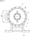
- Fig. 2 is a front view of the speed reducer 10 viewed from the output side (the side where the rotary block 13 is attached), and Fig. 3 is a sectional view along the line III-III in Fig. 2 .
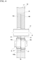
- Fig. 4 is an enlarged sectional view of a part of the speed reducer 10 of Fig. 3
- Fig. 5 is a sectional view of the speed reducer 10 along the line V-V of Fig. 3 .
- an output gear 30, crankshaft gear 31, intermediate gear 32 and the like which will be described later, are not sectioned.
- a retainer 40 and an attachment base 38 which will be described later, are also shown.
- the speed reducer 10 includes a fixed block 14 whose lower end is fixedly installed on an upper surface of a base block 11 (see Fig. 1 ) at one end of the base block 11, a main speed reduction unit 50 coupled to the fixed block 14, and a gear mechanism 51 disposed between the main speed reduction unit 50 and the fixed block 14.
- the motor 2 is attached to the fixed block 14.
- the main speed reduction unit 50 decelerates the rotation input and transmits the decelerated rotation to the output side.
- the gear mechanism 51 reduces the rotation outputted by the motor 2 in the front stage, and the reduced rotation output is further greatly reduced by the main speed reduction unit 50.
- the fixed block 14 includes a disc-shaped base flange 14a with a circular through-hole 25 in the center (see Fig. 3 ), and a leg 14b (see Fig. 2 ) extending downward from the base flange 14a.
- the fixed block 14 is fixed to the base block 11 at a lower end of the leg 14b by a bolt or any other fastening means.
- the main speed reduction unit 50 includes a first carrier block 15A and a second carrier block 15B coupled to the base flange 14a of the fixed block 14, an outer cylinder 17, a plurality (three) of crankshafts 18, and a first pivot gear 19A and a second pivot gear 19B.
- the outer cylinder 17 is rotatably supported via bearings 16 on the outer peripheral side of the first carrier block 15A and the second carrier block 15B.
- the plurality (three) of crankshafts (input rotors) 18 are rotatably supported by the first carrier block 15A and the second carrier block 15B.
- the first pivot gear 19A and the second pivot gear 19B pivot along with two eccentric portions 18a, 18b of each of the crankshafts 18, respectively.
- the speed reducer 10 is disposed on the base block 11 such that the rotational center axis c1 of its output is aligned with the axis o1 of the drive device 1.
- the first carrier block 15A has a disk-like shape with a hole formed therein.
- the first carrier block 15A is overlaid on one end surface of the base flange 14a in the thickness direction and is integrally fixed to the base flange 14A by a bolt(s) or the like.
- the base flange 14a (fixed block 14) and the first carrier block 15A (first block) are stopped from turning (relative rotation) around the rotational center axis c1 by a positioning pin 52 (restraining member).
- the second carrier block 15B is fixed to the end surface of the first carrier block 15A facing away from the base flange 14a by a bolt(s) or the like.
- the second carrier block 15B includes a substrate portion 15Ba and a plurality of support columns (not shown).
- the substrate portion 15Ba has a disk-like shape with a hole formed therein, and the plurality of support columns extend from the end surface of the substrate portion 15Ba toward the first carrier block 15A.
- the end surfaces of the support columns face the end surface of the first carrier block 15A, and the support columns are fixed to the first carrier block 15A.
- An axial gap is maintained between the first carrier block 15A and the substrate portion 15Ba of the second carrier block 15B. In this gap, there are disposed the first pivot gear 19A and the second pivot gear 19B.
- the first pivot gear 19A and the second pivot gear 19B have relief holes (not shown) penetrated by the support columns of the second carrier block 15B.
- the relief holes have sufficiently larger inner diameter than the support columns such that the support columns do not prevent the rotation of the first pivot gear 19A and the second pivot gear 19B.
- the outer cylinder 17 extends from the outer peripheral surface of the first carrier block 15A and the outer peripheral surface of the substrate portion 15Ba of the second carrier block 15B.
- the axially opposite ends of the outer cylinder 17 are rotatably supported by the first carrier block 15A and the substrate portion 15Ba of the second carrier block 15B, respectively, via the bearings 16.
- In the inner peripheral surface of the axially middle region of the outer cylinder 17 (the region facing the outer peripheral surfaces of the first pivot gear 19A and the second pivot gear 19B), there are formed a plurality of pin grooves (not shown) extending in parallel with the rotational center axis c1. Each of the pin grooves receives an inner tooth pin 20 therein.
- the inner tooth pins 20 have a substantially cylindrical shape and are received in a rotatable manner.
- the plurality of inner tooth pins 20 attached to the inner peripheral surface of the outer cylinder 17 face the outer peripheral surfaces of the first pivot gear 19A and the second pivot gear 19B.
- the first pivot gear 19A and the second pivot gear 19B have an outer diameter slightly smaller than the inner diameter of the outer cylinder 17.
- On the outer peripheral surfaces of the first pivot gear 19A and the second pivot gear 19B there are formed outer teeth 19Aa, 19Ba, respectively, so as to contact in a meshing manner with the plurality of inner tooth pins 20 disposed on the inner peripheral surface of the outer cylinder 17.
- the respective numbers of the outer teeth 19Aa, 19Ba formed on the outer peripheral surfaces of the first pivot gear 19A and the second pivot gear 19B are slightly smaller than the number of the inner tooth pins 20 (by one, for example).
- the plurality of crankshafts 18 are arranged in the same circumference centered at the rotational center axis c1 of the first carrier block 15A and the second carrier block 15B.
- Each of the crankshafts 18 is rotatably supported by the first carrier block 15A and the second carrier block 15B via the bearings 22.
- the eccentric portions 18a, 18b of each of the crankshafts 18 penetrate the first pivot gear 19A and the second pivot gear 19B, respectively.
- the eccentric portions 18a, 18b are rotatably engaged via eccentric portion bearings 23 with support holes 21 formed in the first pivot gear 19A and the second pivot gear 19B, respectively.
- the two eccentric portions 18a, 18b of each crankshaft 18 are positioned eccentrically so as to be out of phase with each other by 180° around the axis of the crankshaft 18.
- the eccentric portions 18a, 18b of each crankshaft 18 rotate in the same direction at predetermined radii, such that the first pivot gear 19A and the second pivot gear 19B pivot in the same direction at the same radii.
- the external teeth 19Aa, 19Ba of the first pivot gear 19A and the second pivot gear 19B contact in a meshing manner with the plurality of inner tooth pins 20 retained on the inner peripheral surface of the outer cylinder 17.
- the number of the inner tooth pins 20 retained on the outer cylinder 17 is slightly larger than the respective numbers of the external teeth 19Aa, 19Ba of the first pivot gear 19A and the second pivot gear 19B. Therefore the outer cylinder 17 is pushed and turns in the same direction as the rotating direction of the first and second pivot gears 19A and 19B by a predetermined pitch during a single rotation of the first and second pivot gears 19A and 19B. As a result, the rotations of the crankshafts 18 are largely reduced and then outputted as the rotation of the outer cylinder 17.
- each crankshaft 18 since the eccentric portions 18a, 18b of each crankshaft 18 are positioned eccentrically so as to be out of phase with each other by 180° around the axis, the first pivot gear 19A and the second pivot gear 19B rotate out of phase with each other by 180°.
- an output plate 26 On one axial end of the outer cylinder 17 opposite to the base flange 14a, there is attached an output plate 26 having a disk-like shape with a hole formed therein.
- the output plate 26 covers an end portion of the second carrier block 15B in a non-contact manner, and the rotary block 13 (see Fig. 1 ) for retaining a work can be attached to the axially outer end surface of the output plate by a bolt or any other means.
- a cylindrical portion 27 is attached to the inner periphery of the output plate 26.
- the cylindrical portion 27 penetrates the inside of the second carrier block 15B, the second pivot gear 19B, the first pivot gear 19A, the first carrier block 15A, and the base flange 14a in a non-contact manner.
- the cylindrical portion 27 rotates integrally with the output plate 26.
- the first carrier block 15A and the second carrier block 15B form the first block fixed to the fixed block 14, and the outer cylinder 17 forms the second block rotatably engaged relative to the first block.
- the rotational center of the first block, which are the first carrier block 15A and the second carrier block 15B, relative to the second block which is the outer cylinder 17, coincides with the rotational center axis o1 of the main speed reduction unit 50.
- the main speed reduction mechanism in the main speed reduction unit 50 includes the crankshaft 18, the first pivot gear 19A, the second pivot gear 19B, the internal tooth pins 20 on the inner circumference of the outer cylinder 17, and so on.
- the gear mechanism 51 provided in the front stage includes an input gear 33 coupled to a rotation shaft (not shown) of the motor 2, the output gear 30 rotatably held on the inner peripheral of the first carrier block 15A and the base flange 14a, and an intermediate gear 32 meshing with the input gear 33 and the output gear 30 to transmit the rotation of the input gear 33 to the output gear 30.
- the output gear 30 is larger in diameter than the input gear 33 and has a larger number of teeth than the input gear 33. Therefore, the rotations of the input gear 33 driven by the motor 2 are reduced to a predetermined reduction ratio at the output gear 30.
- the input gear 33 is rotatably supported via a bearing 34 on the edge of the base flange 14a that is spaced away from the through hole 25 in the radially outward direction.
- the axis (axial center) c4 of the input gear 33 is disposed parallel to the rotational center axis c1 of the output side of the speed reducer 10.
- the output gear 30 is formed such that it spans the axial length of the first carrier block 15A and the base flange 14a. External teeth 30a are formed in a middle region of the output gear 30 in the axial direction.
- One end of the output gear 30 in the axial direction is rotatably held on the inner peripheral surface of the first carrier block 15A via a bearing 35B.
- the other end of the output gear 30 in the axial direction is rotatably held on the inner peripheral surface of the through hole 25 of the base flange 14a via a bearing 35A.
- the output gear 30 rotates on the rotational center axis c1 at the end of the first carrier block 15A on the fixed block 14 side.
- a plurality (three) of recesses 28 are formed in an end portion of the first carrier block 15A situated closer to the base flange 14a such that they correspond to the positions of the aforementioned two or more (three in this embodiment) of crankshafts 18.
- Each recess 28 opens in the inner peripheral surface of the first carrier block 15A.
- a crankshaft gear 31 (driven gear) is attached to an end of each crankshaft 18 on the base flange 14a side to transmit its rotation to the crankshaft 18.
- the crankshaft 18 and the crankshaft gear 31 form the input rotor of the main speed reduction unit 50.
- crankshaft gear 31 attached to each crankshaft 18 is disposed in the corresponding recess 28.
- Each crankshaft gear 31 has external teeth 31a.
- the external teeth 31a of each crankshaft gear 31 mesh with the external teeth 30a of the output gear 30 in a region near one end in the axial direction. Therefore, the rotation inputted from the input gear 33 to the output gear 30 via the intermediate gear 32 is transmitted to each crankshaft 18 through the crankshaft gear 31.
- a recess 36 is formed in an end surface of the base flange 14a on the first carrier block 15 side to accommodate the external teeth 33A of the input gear 33 and the intermediate gear 32.
- a mounting base 38 for supporting the intermediate gear 32 is attached to a bottom surface of the recess 36 of the base flange 14a (the surface facing the end surface of the first carrier block 15A).
- a part of the recess 36 is open to the central through-hole 25 of the base flange 14a.
- the intermediate gear 32 disposed in the recess 36 meshes with the outer teeth 30a of the output gear 30 in an open space of the recess 36 on the radially inner side.
- the intermediate gear 32 is rotatably supported by a cylindrical support shaft 39.
- the support shaft 39 is integrally formed with a cylindrical retaining member 40, which has a larger outer diameter and shorter axial length than the support shaft 39.
- the mounting base 38 has a circular retaining hole 41 in which an outer peripheral surface of the retaining member 40 is fitted and fixed.
- the support shaft 39 is fixed in the recess 36 of the base flange 14a (fixed block 14) by fitting the retaining member 40 into the retaining hole 41.
- the intermediate gear 32 which transmits rotation from the input gear 33 to the output gear 30, is rotatably supported on the fixed block 14 side, not on the main speed reduction unit 50 side. Therefore, there is no need to increase the thickness of the main speed reduction unit 50 to support the support shaft 39 of the intermediate gear 32. Accordingly, when the speed reducer 10 of this embodiment is adopted, the main speed reduction unit 50 can be made thinner (the size in the axial direction can be reduced).
- the speed reducer 10 of this embodiment has the recess 36 for accommodating the intermediate gear 32 in the surface of the fixed block 14 facing the main speed reduction unit 50. Therefore, there is no need to provide a deep recess in the surface of the main speed reduction unit 50 facing the fixed block 14 to avoid interference with the intermediate gear 32.
- the main speed reduction unit 50 can be made thinner with this configuration.
- the main speed reduction unit 50 of the speed reducer 10 includes the first carrier block 15A and the second carrier block 15B coupled to the fixed block 14, the outer cylinder 17 that is rotatably engaged with the first and second carrier blocks 15A and 15B, and the main speed reduction mechanism that reduces the rotation of the crankshafts 18 and outputs it to the outer cylinder 17.
- the output gear 30 of the gear mechanism 51 in the front stage is rotatably supported at one end in the axial direction by the first carrier block 15A, and rotatably supported at the other end in the axial direction by the base flange 14a of the fixed block 14.
- the output gear 30, which has a long axial length is supported stably on both sides by the first carrier block 15A and the fixed block 14. Therefore, the speed reducer 10 having such a configuration can reduce the size of the bearing 35B that supports the output gear 30 in the main speed reduction unit 50.
- the main speed reduction unit 50 can be made more thinner and smaller.
- the output gear 30 of the gear mechanism 51 is arranged concentrically with the rotational center axis c1 of the main speed reduction unit 50, and the crankshaft gear 31 that meshes with the output gear 30 and the crankshaft 18 on the the main speed reduction unit 50 side are arranged spaced away from the rotational center axis c1.
- the relative rotation of the first carrier block 15A coupled to the fixed block 14 around the rotational center axis c1 is prevented (relative rotation is restricted) by the positioning pin 52.
- the positioning pin 52 is able to prevent the displacement of the first carrier block 15A relative to the fixed block 14 due to a large reaction force from the output side. Consequently, with this configuration, it is possible to suppress rattling and the like of the first carrier block 15A caused by the operation of the main speed reduction unit 50.
- the present invention is not limited to the above-described embodiments but is susceptible of various design modification within the purport of the present invention.
- the recess 36 is provided in the fixed block 14 and the intermediate gear 32 is housed inside the recess 36.
- a notch or step may be provided in the fixed block 14 to dispose the intermediate gear 32 in the notch or step, and the notch or step may be covered by a lid or the like.
- the outer cylinder 17, which is the second block is configured as the output rotor that rotates by the power of the motor 2.
- the outer cylinder 17, which is the second block may be fixed and installed outside, and the first carrier block 15A and the second carrier block 15B, which are the first block, may serve as the output rotor.
- the rotary block that holds a workpiece or the like is coupled to the first carrier block 15A or the second carrier block 15B.
- the fixed block 14 and the motor 2 rotate together with the first carrier block 15A and the second carrier block 15B.
- the main speed reduction mechanism in the main speed reduction unit 50 includes the crankshaft 18, the first pivot gear 19A, the second pivot gear 19B, the internal tooth pins 20 on the outer cylinder 17.
- the main speed reduction mechanism is not limited to this configuration.
- the main speed reduction mechanism may have any other configuration, such as a planetary gear mechanism, for example.
- 1...drive device 2...motor (rotary drive source), 10...speed reducer, 13...rotary block, 14...fixed block, 15A...first carrier block (first block), 15B...second carrier block (second block), 17...outer cylinder (second block), 18...crankshaft (input rotor, main speed reduction mechanism), 19A...first pivot gear (main speed reduction mechanism), 19B...second pivot gear (main reduction mechanism), 20...internal tooth pins (main speed reduction mechanism), 30...output gear, 31...crankshaft gear (driven gear, input rotor), 32...intermediate gear, 33...input gear, 36...recess, 50...main speed reduction unit, 51...gear mechanism, 52...positioning pin (restraining member)
Landscapes
- Engineering & Computer Science (AREA)
- General Engineering & Computer Science (AREA)
- Mechanical Engineering (AREA)
- Retarders (AREA)
- Gear Transmission (AREA)
Abstract
Description
- The present invention relates to a reducer and a drive device using the speed reducer. This application is based on and claims the benefit of priority from
Japanese Patent Application Serial No. 2019-086559 (filed on April 26, 2019 - Industrial robots, machine tools and the like may include a speed reducer to reduce the speed of rotation of a rotary drive source such as a motor (see, for example, Patent Literature 1).
- The speed reducer described in
Patent Literature 1 has a main speed reduction unit that reduces a speed of rotation of an input side and transmits the rotation to an output side, and an upstream gear mechanism that reduces a speed of rotation of a rotary drive source such as a motor and transmits the rotation to the main speed reduction unit. - The main speed reduction unit includes an outer cylinder block having a substantially circular cylindrical shape, a carrier block rotatably supported by the outer cylinder block, an input rotor (eccentric shaft) rotatably supported at a position radially offset from the rotation center of the carrier block, and a main speed reduction mechanism that reduces rotation of the input rotor and transmits the rotation to the carrier block. The outer cylinder block is fixed to an installation site such as a floor surface, and the carrier block is coupled to a rotary block such as a turntable.
- The main speed reduction mechanism includes a plurality of internal tooth pins on an inner circumference of the outer cylinder block and a pivot gear that pivots and revolves in the inside of the outer cylinder block. The pivot gear has a smaller number of external teeth than the number of internal tooth pins, and the external teeth are configured to engage with the plurality of internal tooth pins. When the pivot gear rotates in engagement with the plurality of internal tooth pins, it revolves relative to the outer cylinder block by a predetermined pitch per single rotation. The input rotor supported by the carrier block has a driven gear that receives an external rotational force and a crank-shaped eccentric portion. The eccentric portion is pivotally engaged with the pivot gear such that it rotates in phase with the pivot gear. The rotation of the input rotor rotates the pivot gear pivotally, and the revolving movement of the pivot gear is reduced at a predetermined reduction ratio while the external teeth of the pivot gear engage the internal tooth pins. As a result, the carrier block rotates at the same speed as the pivot gear.
- The gear mechanism provided in a front stage is supported rotatably on top of the carrier block, and includes an output gear that meshes with the driven gear of the input rotor and an intermediate gear that meshes with the output gear and an input gear of the rotary drive source. The intermediate gear is rotatably supported by a support shaft provided on and protruding from the carrier block. The gear mechanism in the front stage reduces the rotation to a reduction ratio corresponding to the ratio of the number of teeth between the output gear and input gear.
- Patent Literature 1: Publication of
Japanese Patent No. 5231530 - It is difficult to make the main speed reduction unit of the speed reducer thinner (reduce the size in the axial direction) because it contains the intricate main speed reduction mechanism thereinside. However, thinner main speed reduction units (having shorter axial lengths) of this type are desired for various applications.
- In the speed reducer described in
Patent Literature 1, the intermediate gear that is a part of the gear mechanism provided in a front stage is supported by the carrier block provided on the main speed reduction unit side. Therefore the carrier block needs to have an increased thickness (axial length) to accommodate the shaft that supports the intermediate gear in the carrier block. Therefore, it was difficult to realize the thinner main speed reducer unit in the speed reducer described inPatent Literature 1. - The present invention provides a reducer in which a thinner main speed reducer unit is provided, and a drive device using such speed reducer.
- A speed reducer according to one aspect of the invention includes: a main speed reduction unit decelerating rotation from an input side and transmitting decelerated rotation to an output side; a fixed block coupled to the main speed reduction unit and rotatably supporting an input gear coupled to a rotary drive source; an output gear transmitting rotation of the input gear to an input side of the main speed reduction unit; and an intermediate gear meshing with the input gear and the output gear and rotatably supported by the fixed block.
- In the above configuration, once the input gear is rotated by the power of the rotation drive source, the rotation is transmitted to the output gear via the intermediate gear supported on the fixed block side. The rotation transmitted to the output gear is inputted to an input section of the main speed reduction unit, then reduced by the main reduction unit, and outputted from an output section. In this configuration, the intermediate gear is supported on the fixed block side, not on the main speed reduction unit side. Therefore there is no need to increase the thickness of the main speed reduction unit to support the intermediate gear.
- In the speed reducer, a recess may be formed in a surface of the fixed block facing the main speed reduction unit to accommodate the intermediate gear.
- In this case, the intermediate gear is disposed in the recess formed in the fixed block so that there is no need to provide a deep recess in the main speed reduction unit to avoid interference with the intermediate gear. Consequently, the main speed reduction unit can be made thinner with this configuration.
- The main speed reduction unit, includes: a first block coupled to the fixed block; an input rotor rotatably supported by the first block; a second block engaged with the first block such that the second block is rotatable relative to the first block; and a main speed reduction mechanism reducing and outputting rotation of the input rotor to the second block or the first block. One end of the output gear in an axial direction may be rotatably supported by the first block, and the other end of the output gear in the axial direction is rotatably supported by the fixed block.
- Thus, the output gear is supported stably on both sides by the
first block 15A of the main speed reduction unit and the fixed block. Therefore, it is possible to reduce the size of the bearing that supports the output gear rotatably in the main speed reduction unit. When this configuration is adopted, the main speed reduction unit can be made more thinner and smaller. - The main speed reduction unit, includes: a first block coupled to the fixed block; an input rotor rotatably supported by the first block; a second block engaged with the first block such that the second block is rotatable relative to the first block; and a main speed reduction mechanism reducing and outputting rotation of the input rotor to the second block or the first block. The output gear may be disposed concentrically with a center of relative rotation between the first block and the second block. The input rotor may have a driven gear that meshes with the output gear and, the input rotor is spaced away from the relative rotation center, and relative rotation between the fixed block and the first block around the relative rotation center is prevented by a restraining member.
- In this case, when the rotation is transmitted to the input rotor through the driven gear, the restraining member is able to prevent the displacement of the first block relative to the fixed block due to a reaction force from the output side. Consequently, with this configuration, it is possible to suppress rattling and the like of the first block caused by the operation of the main speed reduction unit.
- A speed reducer according to another aspect of the invention includes: a main speed reduction unit decelerating rotation from an input side and transmitting decelerated rotation to an output side; a fixed block coupled to the main speed reduction unit and rotatably supporting an input gear coupled to a rotary drive source; an output gear transmitting rotation of the input gear to an input side of the main speed reduction unit; and an intermediate gear meshing with the input gear and the output gear and rotatably supported by the fixed block. The main speed reduction unit, includes: a first block coupled to the fixed block; an input rotor rotatably supported by the first block; a second block engaged with the first block such that the second block is rotatable relative to the first block; and a main speed reduction mechanism outputting rotation of the input rotor to the second block or the first block. A main speed reduction mechanism outputting rotation of the input rotor to the second block or the first block, a main speed reduction mechanism outputting rotation of the input rotor to the second block or the first block, and the intermediate gear is rotatably supported by the fixed block in the recess.
- A drive device according to another aspect of the invention includes: a speed reduction mechanism reducing rotation inputted by a rotary drive source and outputting decelerated rotation; and a rotary block coupled to an output of the speed reducer. The speed reducer includes: a main speed reduction unit decelerating rotation from an input side and transmitting decelerated rotation to an output side; a fixed block coupled to the main speed reduction unit and rotatably supporting an input gear coupled to a rotary drive source; a fixed block coupled to the main speed reduction unit and rotatably supporting an input gear coupled to a rotary drive source; and an intermediate gear meshing with the input gear and the output gear and rotatably supported by the fixed block.
- In the speed reducer and drive device described above, the main speed reduction gear unit can be made thinner since it is not necessary to increase the thickness on the main speed reduction unit side to support the intermediate gears.
-
-
Fig. 1 is a perspective view of a drive device according to an embodiment of the invention. -
Fig. 2 is a front view of a speed reducer according to the embodiment. -
Fig. 3 is a sectional view along the line III-III inFig. 2 . -
Fig. 4 is an enlarged sectional view of a part of the speed reducer according to the embodiment ofFig. 3 . -
Fig. 5 is a sectional view of the speed reducer according to the embodiment along the line V-V inFig. 3 . - The embodiments of the present invention will be hereinafter described with reference to the drawings.
Fig.1 is a perspective view of adrive device 1 used for welding and component assembly and the like. Thedrive device 1 includes: abase block 11 installed on a floor surface F; aspeed reducer 10 fixedly installed on an upper surface of thebase block 11 on one end side in the longitudinal direction of thebase block 11; amotor 2 that is a rotary drive source driving thespeed reducer 10; aretainer 12 fixedly installed on an upper surface of thebase block 11 on the other end side thereof in the longitudinal direction; and arotary block 13 supported at both end portions thereof in its longitudinal direction by thespeed reducer 10 and theretainer 12. Themotor 2 is integrally mounted to the input side of thespeed reducer 10. The speed reducer 10 reduces rotation of themotor 2 and transmits the reduced rotation to one end of therotary block 13 in the longitudinal direction. Theretainer 12 rotatably supports the other end side of therotary block 13 in the longitudinal direction. Therotary block 13 receives the power from themotor 2 via thespeed reducer 10 and rotates about an axis (shaft center) o1 that extends substantially along the horizontal direction. - In this embodiment, the
rotary block 13 has two or more work support surfaces 13a around the axis o1. A work W may be mounted on eachwork support surface 13a. The work W mounted on thework support surface 13a is moved toward a working position by the rotation of therotary block 13 caused by themotor 2. At the working position, there may be installed a workingdevice 3 such as a welding robot. -
Fig. 2 is a front view of thespeed reducer 10 viewed from the output side (the side where therotary block 13 is attached), andFig. 3 is a sectional view along the line III-III inFig. 2 .Fig. 4 is an enlarged sectional view of a part of thespeed reducer 10 ofFig. 3 , andFig. 5 is a sectional view of thespeed reducer 10 along the line V-V ofFig. 3 . InFig. 5 , anoutput gear 30,crankshaft gear 31,intermediate gear 32 and the like, which will be described later, are not sectioned. InFig. 5 , aretainer 40 and anattachment base 38, which will be described later, are also shown. Thespeed reducer 10 includes a fixedblock 14 whose lower end is fixedly installed on an upper surface of a base block 11 (seeFig. 1 ) at one end of thebase block 11, a mainspeed reduction unit 50 coupled to the fixedblock 14, and agear mechanism 51 disposed between the mainspeed reduction unit 50 and the fixedblock 14. Themotor 2 is attached to the fixedblock 14. The mainspeed reduction unit 50 decelerates the rotation input and transmits the decelerated rotation to the output side. In thespeed reducer 10 of this embodiment, thegear mechanism 51 reduces the rotation outputted by themotor 2 in the front stage, and the reduced rotation output is further greatly reduced by the mainspeed reduction unit 50. - The fixed
block 14 includes a disc-shapedbase flange 14a with a circular through-hole 25 in the center (seeFig. 3 ), and aleg 14b (seeFig. 2 ) extending downward from thebase flange 14a. The fixedblock 14 is fixed to thebase block 11 at a lower end of theleg 14b by a bolt or any other fastening means. - The main
speed reduction unit 50 includes afirst carrier block 15A and asecond carrier block 15B coupled to thebase flange 14a of the fixedblock 14, anouter cylinder 17, a plurality (three) ofcrankshafts 18, and afirst pivot gear 19A and asecond pivot gear 19B. Theouter cylinder 17 is rotatably supported viabearings 16 on the outer peripheral side of thefirst carrier block 15A and thesecond carrier block 15B. The plurality (three) of crankshafts (input rotors) 18 are rotatably supported by thefirst carrier block 15A and thesecond carrier block 15B. Thefirst pivot gear 19A and thesecond pivot gear 19B pivot along with twoeccentric portions crankshafts 18, respectively. Thespeed reducer 10 is disposed on thebase block 11 such that the rotational center axis c1 of its output is aligned with the axis o1 of thedrive device 1. - The
first carrier block 15A has a disk-like shape with a hole formed therein. Thefirst carrier block 15A is overlaid on one end surface of thebase flange 14a in the thickness direction and is integrally fixed to the base flange 14A by a bolt(s) or the like. Thebase flange 14a (fixed block 14) and thefirst carrier block 15A (first block) are stopped from turning (relative rotation) around the rotational center axis c1 by a positioning pin 52 (restraining member). Thesecond carrier block 15B is fixed to the end surface of thefirst carrier block 15A facing away from thebase flange 14a by a bolt(s) or the like. Thesecond carrier block 15B includes a substrate portion 15Ba and a plurality of support columns (not shown). The substrate portion 15Ba has a disk-like shape with a hole formed therein, and the plurality of support columns extend from the end surface of the substrate portion 15Ba toward thefirst carrier block 15A. In thesecond carrier block 15B, the end surfaces of the support columns face the end surface of thefirst carrier block 15A, and the support columns are fixed to thefirst carrier block 15A. An axial gap is maintained between thefirst carrier block 15A and the substrate portion 15Ba of thesecond carrier block 15B. In this gap, there are disposed thefirst pivot gear 19A and thesecond pivot gear 19B. Thefirst pivot gear 19A and thesecond pivot gear 19B have relief holes (not shown) penetrated by the support columns of thesecond carrier block 15B. The relief holes have sufficiently larger inner diameter than the support columns such that the support columns do not prevent the rotation of thefirst pivot gear 19A and thesecond pivot gear 19B. - The
outer cylinder 17 extends from the outer peripheral surface of thefirst carrier block 15A and the outer peripheral surface of the substrate portion 15Ba of thesecond carrier block 15B. The axially opposite ends of theouter cylinder 17 are rotatably supported by thefirst carrier block 15A and the substrate portion 15Ba of thesecond carrier block 15B, respectively, via thebearings 16. In the inner peripheral surface of the axially middle region of the outer cylinder 17 (the region facing the outer peripheral surfaces of thefirst pivot gear 19A and thesecond pivot gear 19B), there are formed a plurality of pin grooves (not shown) extending in parallel with the rotational center axis c1. Each of the pin grooves receives aninner tooth pin 20 therein. The inner tooth pins 20 have a substantially cylindrical shape and are received in a rotatable manner. The plurality of inner tooth pins 20 attached to the inner peripheral surface of theouter cylinder 17 face the outer peripheral surfaces of thefirst pivot gear 19A and thesecond pivot gear 19B. - The
first pivot gear 19A and thesecond pivot gear 19B have an outer diameter slightly smaller than the inner diameter of theouter cylinder 17. On the outer peripheral surfaces of thefirst pivot gear 19A and thesecond pivot gear 19B, there are formed outer teeth 19Aa, 19Ba, respectively, so as to contact in a meshing manner with the plurality of inner tooth pins 20 disposed on the inner peripheral surface of theouter cylinder 17. The respective numbers of the outer teeth 19Aa, 19Ba formed on the outer peripheral surfaces of thefirst pivot gear 19A and thesecond pivot gear 19B are slightly smaller than the number of the inner tooth pins 20 (by one, for example). - The plurality of
crankshafts 18 are arranged in the same circumference centered at the rotational center axis c1 of thefirst carrier block 15A and thesecond carrier block 15B. Each of thecrankshafts 18 is rotatably supported by thefirst carrier block 15A and the second carrier block 15B via thebearings 22. Theeccentric portions crankshafts 18 penetrate thefirst pivot gear 19A and thesecond pivot gear 19B, respectively. Theeccentric portions eccentric portion bearings 23 with support holes 21 formed in thefirst pivot gear 19A and thesecond pivot gear 19B, respectively. The twoeccentric portions crankshaft 18 are positioned eccentrically so as to be out of phase with each other by 180° around the axis of thecrankshaft 18. - When the plurality of
crankshafts 18 receive an external force and rotate in one direction, theeccentric portions crankshaft 18 rotate in the same direction at predetermined radii, such that thefirst pivot gear 19A and thesecond pivot gear 19B pivot in the same direction at the same radii. Simultaneously, the external teeth 19Aa, 19Ba of thefirst pivot gear 19A and thesecond pivot gear 19B contact in a meshing manner with the plurality of inner tooth pins 20 retained on the inner peripheral surface of theouter cylinder 17. - In the
speed reducer 10 of the embodiment, the number of the inner tooth pins 20 retained on theouter cylinder 17 is slightly larger than the respective numbers of the external teeth 19Aa, 19Ba of thefirst pivot gear 19A and thesecond pivot gear 19B. Therefore theouter cylinder 17 is pushed and turns in the same direction as the rotating direction of the first and second pivot gears 19A and 19B by a predetermined pitch during a single rotation of the first and second pivot gears 19A and 19B. As a result, the rotations of thecrankshafts 18 are largely reduced and then outputted as the rotation of theouter cylinder 17. In the embodiment, since theeccentric portions crankshaft 18 are positioned eccentrically so as to be out of phase with each other by 180° around the axis, thefirst pivot gear 19A and thesecond pivot gear 19B rotate out of phase with each other by 180°. - On one axial end of the
outer cylinder 17 opposite to thebase flange 14a, there is attached anoutput plate 26 having a disk-like shape with a hole formed therein. Theoutput plate 26 covers an end portion of the second carrier block 15B in a non-contact manner, and the rotary block 13 (seeFig. 1 ) for retaining a work can be attached to the axially outer end surface of the output plate by a bolt or any other means. Acylindrical portion 27 is attached to the inner periphery of theoutput plate 26. Thecylindrical portion 27 penetrates the inside of thesecond carrier block 15B, thesecond pivot gear 19B, thefirst pivot gear 19A, thefirst carrier block 15A, and thebase flange 14a in a non-contact manner. Thecylindrical portion 27 rotates integrally with theoutput plate 26. - In this embodiment, the
first carrier block 15A and the second carrier block 15B form the first block fixed to the fixedblock 14, and theouter cylinder 17 forms the second block rotatably engaged relative to the first block. The rotational center of the first block, which are thefirst carrier block 15A and thesecond carrier block 15B, relative to the second block which is theouter cylinder 17, coincides with the rotational center axis o1 of the mainspeed reduction unit 50. The main speed reduction mechanism in the mainspeed reduction unit 50 includes thecrankshaft 18, thefirst pivot gear 19A, thesecond pivot gear 19B, the internal tooth pins 20 on the inner circumference of theouter cylinder 17, and so on. - The
gear mechanism 51 provided in the front stage includes aninput gear 33 coupled to a rotation shaft (not shown) of themotor 2, theoutput gear 30 rotatably held on the inner peripheral of thefirst carrier block 15A and thebase flange 14a, and anintermediate gear 32 meshing with theinput gear 33 and theoutput gear 30 to transmit the rotation of theinput gear 33 to theoutput gear 30. Theoutput gear 30 is larger in diameter than theinput gear 33 and has a larger number of teeth than theinput gear 33. Therefore, the rotations of theinput gear 33 driven by themotor 2 are reduced to a predetermined reduction ratio at theoutput gear 30. - The
input gear 33 is rotatably supported via abearing 34 on the edge of thebase flange 14a that is spaced away from the throughhole 25 in the radially outward direction. The axis (axial center) c4 of theinput gear 33 is disposed parallel to the rotational center axis c1 of the output side of thespeed reducer 10. - The
output gear 30 is formed such that it spans the axial length of thefirst carrier block 15A and thebase flange 14a.External teeth 30a are formed in a middle region of theoutput gear 30 in the axial direction. One end of theoutput gear 30 in the axial direction is rotatably held on the inner peripheral surface of thefirst carrier block 15A via abearing 35B. The other end of theoutput gear 30 in the axial direction is rotatably held on the inner peripheral surface of the throughhole 25 of thebase flange 14a via abearing 35A. Theoutput gear 30 rotates on the rotational center axis c1 at the end of thefirst carrier block 15A on the fixedblock 14 side. - A plurality (three) of
recesses 28 are formed in an end portion of thefirst carrier block 15A situated closer to thebase flange 14a such that they correspond to the positions of the aforementioned two or more (three in this embodiment) ofcrankshafts 18. Eachrecess 28 opens in the inner peripheral surface of thefirst carrier block 15A. A crankshaft gear 31 (driven gear) is attached to an end of eachcrankshaft 18 on thebase flange 14a side to transmit its rotation to thecrankshaft 18. In this embodiment, thecrankshaft 18 and thecrankshaft gear 31 form the input rotor of the mainspeed reduction unit 50. - The
crankshaft gear 31 attached to eachcrankshaft 18 is disposed in thecorresponding recess 28. Eachcrankshaft gear 31 hasexternal teeth 31a. Theexternal teeth 31a of eachcrankshaft gear 31 mesh with theexternal teeth 30a of theoutput gear 30 in a region near one end in the axial direction. Therefore, the rotation inputted from theinput gear 33 to theoutput gear 30 via theintermediate gear 32 is transmitted to eachcrankshaft 18 through thecrankshaft gear 31. - A
recess 36 is formed in an end surface of thebase flange 14a on the first carrier block 15 side to accommodate the external teeth 33A of theinput gear 33 and theintermediate gear 32. A mountingbase 38 for supporting theintermediate gear 32 is attached to a bottom surface of therecess 36 of thebase flange 14a (the surface facing the end surface of thefirst carrier block 15A). A part of therecess 36 is open to the central through-hole 25 of thebase flange 14a. Theintermediate gear 32 disposed in therecess 36 meshes with theouter teeth 30a of theoutput gear 30 in an open space of therecess 36 on the radially inner side. - The
intermediate gear 32 is rotatably supported by acylindrical support shaft 39. Thesupport shaft 39 is integrally formed with a cylindrical retainingmember 40, which has a larger outer diameter and shorter axial length than thesupport shaft 39. The mountingbase 38 has acircular retaining hole 41 in which an outer peripheral surface of the retainingmember 40 is fitted and fixed. Thesupport shaft 39 is fixed in therecess 36 of thebase flange 14a (fixed block 14) by fitting the retainingmember 40 into the retaininghole 41. - As described above, in the
speed reducer 10 of this embodiment, theintermediate gear 32, which transmits rotation from theinput gear 33 to theoutput gear 30, is rotatably supported on the fixedblock 14 side, not on the mainspeed reduction unit 50 side. Therefore, there is no need to increase the thickness of the mainspeed reduction unit 50 to support thesupport shaft 39 of theintermediate gear 32. Accordingly, when thespeed reducer 10 of this embodiment is adopted, the mainspeed reduction unit 50 can be made thinner (the size in the axial direction can be reduced). - In addition, the
speed reducer 10 of this embodiment has therecess 36 for accommodating theintermediate gear 32 in the surface of the fixedblock 14 facing the mainspeed reduction unit 50. Therefore, there is no need to provide a deep recess in the surface of the mainspeed reduction unit 50 facing the fixedblock 14 to avoid interference with theintermediate gear 32. The mainspeed reduction unit 50 can be made thinner with this configuration. - The main
speed reduction unit 50 of thespeed reducer 10 includes thefirst carrier block 15A and thesecond carrier block 15B coupled to the fixedblock 14, theouter cylinder 17 that is rotatably engaged with the first and second carrier blocks 15A and 15B, and the main speed reduction mechanism that reduces the rotation of thecrankshafts 18 and outputs it to theouter cylinder 17. Theoutput gear 30 of thegear mechanism 51 in the front stage is rotatably supported at one end in the axial direction by thefirst carrier block 15A, and rotatably supported at the other end in the axial direction by thebase flange 14a of the fixedblock 14. Thus, theoutput gear 30, which has a long axial length, is supported stably on both sides by thefirst carrier block 15A and the fixedblock 14. Therefore, thespeed reducer 10 having such a configuration can reduce the size of thebearing 35B that supports theoutput gear 30 in the mainspeed reduction unit 50. When this configuration is adopted, the mainspeed reduction unit 50 can be made more thinner and smaller. - Furthermore, in the
speed reducer 10 of the embodiment, theoutput gear 30 of thegear mechanism 51 is arranged concentrically with the rotational center axis c1 of the mainspeed reduction unit 50, and thecrankshaft gear 31 that meshes with theoutput gear 30 and thecrankshaft 18 on the the mainspeed reduction unit 50 side are arranged spaced away from the rotational center axis c1. The relative rotation of thefirst carrier block 15A coupled to the fixedblock 14 around the rotational center axis c1 is prevented (relative rotation is restricted) by the positioning pin 52. Therefore, when the rotation of theoutput gear 30 is transmitted to thecrankshafts 18 through the crankshaft gears 31, the positioning pin 52 is able to prevent the displacement of thefirst carrier block 15A relative to the fixedblock 14 due to a large reaction force from the output side. Consequently, with this configuration, it is possible to suppress rattling and the like of thefirst carrier block 15A caused by the operation of the mainspeed reduction unit 50. - The present invention is not limited to the above-described embodiments but is susceptible of various design modification within the purport of the present invention. For example, in the above embodiment, the
recess 36 is provided in the fixedblock 14 and theintermediate gear 32 is housed inside therecess 36. Alternatively, a notch or step may be provided in the fixedblock 14 to dispose theintermediate gear 32 in the notch or step, and the notch or step may be covered by a lid or the like. - In the above embodiment, the
outer cylinder 17, which is the second block, is configured as the output rotor that rotates by the power of themotor 2. Alternatively, theouter cylinder 17, which is the second block, may be fixed and installed outside, and thefirst carrier block 15A and thesecond carrier block 15B, which are the first block, may serve as the output rotor. In this case, the rotary block that holds a workpiece or the like is coupled to thefirst carrier block 15A or thesecond carrier block 15B. The fixedblock 14 and themotor 2 rotate together with thefirst carrier block 15A and thesecond carrier block 15B. - Further, in the above embodiment, the main speed reduction mechanism in the main
speed reduction unit 50 includes thecrankshaft 18, thefirst pivot gear 19A, thesecond pivot gear 19B, the internal tooth pins 20 on theouter cylinder 17. However, the main speed reduction mechanism is not limited to this configuration. The main speed reduction mechanism may have any other configuration, such as a planetary gear mechanism, for example. - 1...drive device, 2...motor (rotary drive source), 10...speed reducer, 13...rotary block, 14...fixed block, 15A...first carrier block (first block), 15B...second carrier block (second block), 17...outer cylinder (second block), 18...crankshaft (input rotor, main speed reduction mechanism), 19A...first pivot gear (main speed reduction mechanism), 19B...second pivot gear (main reduction mechanism), 20...internal tooth pins (main speed reduction mechanism), 30...output gear, 31...crankshaft gear (driven gear, input rotor), 32...intermediate gear, 33...input gear, 36...recess, 50...main speed reduction unit, 51...gear mechanism, 52...positioning pin (restraining member)
Claims (6)
- A speed reducer, comprising:a main speed reduction unit decelerating rotation from an input side and transmitting decelerated rotation to an output side;a fixed block coupled to the main speed reduction unit and rotatably supporting an input gear coupled to a rotary drive source;an output gear transmitting rotation of the input gear to an input side of the main speed reduction unit; andan intermediate gear meshing with the input gear and the output gear and rotatably supported by the fixed block.
- The speed reducer of claim 1, wherein a recess is formed in a surface of the fixed block facing the main speed reduction unit to accommodate the intermediate gear.
- The speed reducer of claim 1 or 2, wherein the main speed reduction unit includes:a first block coupled to the fixed block;an input rotor rotatably supported by the first block;a second block engaged with the first block such that the second block is rotatable relative to the first block; anda main speed reduction mechanism outputting rotation of the input rotor to the second block or the first block,wherein one end of the output gear in an axial direction is rotatably supported by the first block, and the other end of the output gear in the axial direction is rotatably supported by the fixed block.
- The speed reducer of claim 1 or 2, wherein the main speed reduction unit includes:a first block coupled to the fixed block;an input rotor rotatably supported by the first block;a second block engaged with the first block such that it is rotatable relative to the first block; anda main speed reduction mechanism outputting rotation of the input rotor to the second block or the first block,wherein the output gear is disposed concentrically with a center of relative rotation between the first block and the second block,wherein the input rotor has a driven gear that meshes with the output gear and, the input rotor is spaced away from the relative rotation center, andwherein relative rotation between the fixed block and the first block around the relative rotation center is prevented by a restraining member.
- A speed reducer, comprising:a main speed reduction unit decelerating rotation from an input side and transmitting decelerated rotation to an output side;a fixed block coupled to the main speed reduction unit and rotatably supporting an input gear coupled to a rotary drive source;an output gear transmitting rotation of the input gear to an input side of the main speed reduction unit; andan intermediate gear meshing with the input gear and the output gear and rotatably supported by the fixed block,wherein the main speed reduction unit includes:a first block coupled to the fixed block;an input rotor rotatably supported by the first block;a second block engaged with the first block such that it is rotatable relative to the first block; anda main speed reduction mechanism outputting rotation of the input rotor to the second block or the first block,wherein the output gear is rotatably supported at an end portion of the first block on the fixed block side at a position concentric to a center of relative rotation between the first block and the second block,wherein a recess is formed in a surface of the fixed block facing the main speed reduction unit to accommodate the intermediate gear, andwherein the intermediate gear is rotatably supported by the fixed block in the recess.
- A drive device, comprising:a speed reducer decelerating rotation inputted by a rotary drive source and outputting decelerated rotation; anda rotary block coupled to an output of the speed reducer,wherein the speed reducer includes:a main speed reduction unit decelerating rotation from an input side and transmitting decelerated rotation to an output side;a fixed block coupled to the main speed reduction unit and rotatably supporting an input gear coupled to a rotary drive source;an output gear transmitting rotation of the input gear to an input side of the main speed reduction unit; andan intermediate gear meshing with the input gear and the output gear and rotatably supported by the fixed block.
Applications Claiming Priority (2)
| Application Number | Priority Date | Filing Date | Title |
|---|---|---|---|
| JP2019086559A JP2020183763A (en) | 2019-04-26 | 2019-04-26 | A speed reducer and a drive device using the speed reducer |
| PCT/JP2020/013447 WO2020217834A1 (en) | 2019-04-26 | 2020-03-25 | Reduction gear and drive device using reduction gear |
Publications (2)
| Publication Number | Publication Date |
|---|---|
| EP3961063A1 true EP3961063A1 (en) | 2022-03-02 |
| EP3961063A4 EP3961063A4 (en) | 2023-04-12 |
Family
ID=72942247
Family Applications (1)
| Application Number | Title | Priority Date | Filing Date |
|---|---|---|---|
| EP20795537.8A Pending EP3961063A4 (en) | 2019-04-26 | 2020-03-25 | REDUCTION GEAR AND DRIVE DEVICE USING A REDUCTION GEAR |
Country Status (7)
| Country | Link |
|---|---|
| US (1) | US11852217B2 (en) |
| EP (1) | EP3961063A4 (en) |
| JP (3) | JP2020183763A (en) |
| KR (1) | KR20220002267A (en) |
| CN (1) | CN113614411B (en) |
| TW (1) | TW202040028A (en) |
| WO (1) | WO2020217834A1 (en) |
Family Cites Families (25)
| Publication number | Priority date | Publication date | Assignee | Title |
|---|---|---|---|---|
| JPS5231530B1 (en) | 1971-05-04 | 1977-08-16 | ||
| JPH05231530A (en) | 1992-02-20 | 1993-09-07 | Toyota Motor Corp | Control device for vehicle lock-up clutch |
| JPH07124883A (en) | 1993-10-27 | 1995-05-16 | Yaskawa Electric Corp | Drive structure of swivel part of industrial robot |
| JP3727135B2 (en) * | 1997-03-13 | 2005-12-14 | ナブテスコ株式会社 | Hydraulic drive |
| JP4020560B2 (en) * | 2000-02-07 | 2007-12-12 | ナブテスコ株式会社 | Eccentric rocking speed reducer |
| US20080295623A1 (en) * | 2004-08-11 | 2008-12-04 | Nabtesco Corporation | Speed Reducer to be Attached to Articulated Portion Industrial Robot |
| EP2052818B1 (en) * | 2005-04-25 | 2011-04-13 | Nabtesco Corporation | Eccentrical oscillation speed reducer for the turning portion structure of industrial robot |
| DK1988307T3 (en) * | 2005-09-26 | 2012-01-16 | Nabtesco Corp | Reducers |
| CN101375083B (en) * | 2006-01-26 | 2012-10-17 | 纳博特斯克株式会社 | Reducer |
| EP2077404A1 (en) * | 2006-09-01 | 2009-07-08 | Nabtesco Corporation | Reduction gear |
| EP2149724B1 (en) * | 2007-05-23 | 2013-05-15 | Nabtesco Corporation | Reduction gear device |
| WO2009057526A1 (en) * | 2007-10-31 | 2009-05-07 | Nabtesco Corporation | Speed reducer |
| WO2009098945A1 (en) * | 2008-02-07 | 2009-08-13 | Nabtesco Corporation | Gear power transmission device |
| US8444520B2 (en) * | 2008-03-28 | 2013-05-21 | Nabtesco Corporation | Gear device |
| JP2010014177A (en) * | 2008-07-02 | 2010-01-21 | Nabtesco Corp | Eccentric rocking type gear transmission device |
| ES2425080T3 (en) * | 2008-08-21 | 2013-10-11 | Nabtesco Corporation | Gear transmission device and solar power generation device |
| JP5155773B2 (en) | 2008-08-21 | 2013-03-06 | ナブテスコ株式会社 | Gear transmission and solar power generation device using the same |
| JP5193072B2 (en) * | 2009-01-09 | 2013-05-08 | ナブテスコ株式会社 | Gear transmission |
| JP2014005900A (en) * | 2012-06-26 | 2014-01-16 | Nabtesco Corp | Eccentric rocking gear device |
| JP5998423B2 (en) * | 2012-12-20 | 2016-09-28 | 株式会社不二越 | Decelerator |
| JP6181961B2 (en) * | 2013-04-15 | 2017-08-16 | ナブテスコ株式会社 | Eccentric oscillating gear unit |
| CN105090416B (en) * | 2014-05-20 | 2019-04-30 | 德昌电机(深圳)有限公司 | Seat adjusts driving device |
| JP6659232B2 (en) | 2015-04-14 | 2020-03-04 | ナブテスコ株式会社 | Gear transmission |
| CN205859053U (en) * | 2016-07-29 | 2017-01-04 | 纳博特斯克有限公司 | Reductor |
| JP2019086559A (en) | 2017-11-02 | 2019-06-06 | サンアプロ株式会社 | Resin composition for negative photoresist and cured film |
-
2019
- 2019-04-26 JP JP2019086559A patent/JP2020183763A/en active Pending
-
2020
- 2020-03-25 EP EP20795537.8A patent/EP3961063A4/en active Pending
- 2020-03-25 WO PCT/JP2020/013447 patent/WO2020217834A1/en not_active Ceased
- 2020-03-25 KR KR1020217029945A patent/KR20220002267A/en not_active Ceased
- 2020-03-25 CN CN202080022578.0A patent/CN113614411B/en active Active
- 2020-03-25 US US17/442,070 patent/US11852217B2/en active Active
- 2020-03-26 TW TW109110205A patent/TW202040028A/en unknown
-
2023
- 2023-11-08 JP JP2023190766A patent/JP7624049B2/en active Active
-
2024
- 2024-12-03 JP JP2024210596A patent/JP2025023233A/en active Pending
Also Published As
| Publication number | Publication date |
|---|---|
| EP3961063A4 (en) | 2023-04-12 |
| TW202040028A (en) | 2020-11-01 |
| WO2020217834A1 (en) | 2020-10-29 |
| CN113614411A (en) | 2021-11-05 |
| JP7624049B2 (en) | 2025-01-29 |
| US11852217B2 (en) | 2023-12-26 |
| CN113614411B (en) | 2024-12-24 |
| JP2023184681A (en) | 2023-12-28 |
| US20220170532A1 (en) | 2022-06-02 |
| JP2020183763A (en) | 2020-11-12 |
| KR20220002267A (en) | 2022-01-06 |
| JP2025023233A (en) | 2025-02-14 |
Similar Documents
| Publication | Publication Date | Title |
|---|---|---|
| JP5356462B2 (en) | Turning structure of industrial robot using eccentric rocking type reducer | |
| EP2450595B1 (en) | Planetary gear mechanism | |
| KR102580787B1 (en) | Gear transmission device | |
| JP5301371B2 (en) | 2-axis rotary positioner | |
| JP2019158143A (en) | Transmission device | |
| US11852220B2 (en) | Gear mechanism, speed reducer and drive device using speed reducer | |
| EP3763968B1 (en) | Speed reducer | |
| US11852217B2 (en) | Speed reducer and drive device using the same | |
| US11549569B2 (en) | Speed reducing device and drive device | |
| CN112145631B (en) | Pin holding mechanism and speed reducer | |
| JP7551884B2 (en) | Rotating Equipment | |
| CN112709787A (en) | Shell of speed reducer, speed reducer and industrial robot | |
| KR20200066200A (en) | Rotation mechanism of industrial machinery, speed reducer, industrial machine and drive device | |
| CN115507156A (en) | reducer | |
| CN113775714B (en) | Reducer and drive unit | |
| KR20200102346A (en) | Gear device and carrier | |
| JP7398217B2 (en) | Gear mechanism, reducer, and drive device using the reducer | |
| JP2024024381A (en) | Reducer and rotating equipment | |
| JP2025146438A (en) | Rotating device | |
| JP2024032209A (en) | Decelerator | |
| JP2010071167A (en) | Speed reduction gear for wind mill |
Legal Events
| Date | Code | Title | Description |
|---|---|---|---|
| STAA | Information on the status of an ep patent application or granted ep patent |
Free format text: STATUS: THE INTERNATIONAL PUBLICATION HAS BEEN MADE |
|
| PUAI | Public reference made under article 153(3) epc to a published international application that has entered the european phase |
Free format text: ORIGINAL CODE: 0009012 |
|
| STAA | Information on the status of an ep patent application or granted ep patent |
Free format text: STATUS: REQUEST FOR EXAMINATION WAS MADE |
|
| 17P | Request for examination filed |
Effective date: 20210923 |
|
| AK | Designated contracting states |
Kind code of ref document: A1 Designated state(s): AL AT BE BG CH CY CZ DE DK EE ES FI FR GB GR HR HU IE IS IT LI LT LU LV MC MK MT NL NO PL PT RO RS SE SI SK SM TR |
|
| DAV | Request for validation of the european patent (deleted) | ||
| DAX | Request for extension of the european patent (deleted) | ||
| A4 | Supplementary search report drawn up and despatched |
Effective date: 20230315 |
|
| RIC1 | Information provided on ipc code assigned before grant |
Ipc: F16H 1/32 20060101AFI20230309BHEP |
|
| P01 | Opt-out of the competence of the unified patent court (upc) registered |
Effective date: 20230523 |
|
| STAA | Information on the status of an ep patent application or granted ep patent |
Free format text: STATUS: EXAMINATION IS IN PROGRESS |
|
| 17Q | First examination report despatched |
Effective date: 20260116 |