EP3961042A1 - Wind wheel apparatus and air blowing device - Google Patents
Wind wheel apparatus and air blowing device Download PDFInfo
- Publication number
- EP3961042A1 EP3961042A1 EP19939294.5A EP19939294A EP3961042A1 EP 3961042 A1 EP3961042 A1 EP 3961042A1 EP 19939294 A EP19939294 A EP 19939294A EP 3961042 A1 EP3961042 A1 EP 3961042A1
- Authority
- EP
- European Patent Office
- Prior art keywords
- air duct
- wind wheel
- side plate
- heat generating
- wheel device
- Prior art date
- Legal status (The legal status is an assumption and is not a legal conclusion. Google has not performed a legal analysis and makes no representation as to the accuracy of the status listed.)
- Pending
Links
Images




Classifications
-
- F—MECHANICAL ENGINEERING; LIGHTING; HEATING; WEAPONS; BLASTING
- F04—POSITIVE - DISPLACEMENT MACHINES FOR LIQUIDS; PUMPS FOR LIQUIDS OR ELASTIC FLUIDS
- F04D—NON-POSITIVE-DISPLACEMENT PUMPS
- F04D17/00—Radial-flow pumps, e.g. centrifugal pumps; Helico-centrifugal pumps
- F04D17/02—Radial-flow pumps, e.g. centrifugal pumps; Helico-centrifugal pumps having non-centrifugal stages, e.g. centripetal
- F04D17/04—Radial-flow pumps, e.g. centrifugal pumps; Helico-centrifugal pumps having non-centrifugal stages, e.g. centripetal of transverse-flow type
-
- F—MECHANICAL ENGINEERING; LIGHTING; HEATING; WEAPONS; BLASTING
- F04—POSITIVE - DISPLACEMENT MACHINES FOR LIQUIDS; PUMPS FOR LIQUIDS OR ELASTIC FLUIDS
- F04D—NON-POSITIVE-DISPLACEMENT PUMPS
- F04D29/00—Details, component parts, or accessories
- F04D29/26—Rotors specially for elastic fluids
- F04D29/28—Rotors specially for elastic fluids for centrifugal or helico-centrifugal pumps for radial-flow or helico-centrifugal pumps
- F04D29/281—Rotors specially for elastic fluids for centrifugal or helico-centrifugal pumps for radial-flow or helico-centrifugal pumps for fans or blowers
-
- B—PERFORMING OPERATIONS; TRANSPORTING
- B60—VEHICLES IN GENERAL
- B60H—ARRANGEMENTS OF HEATING, COOLING, VENTILATING OR OTHER AIR-TREATING DEVICES SPECIALLY ADAPTED FOR PASSENGER OR GOODS SPACES OF VEHICLES
- B60H1/00—Heating, cooling or ventilating devices
- B60H1/00457—Ventilation unit, e.g. combined with a radiator
- B60H1/00471—The ventilator being of the radial type, i.e. with radial expulsion of the air
-
- B—PERFORMING OPERATIONS; TRANSPORTING
- B60—VEHICLES IN GENERAL
- B60H—ARRANGEMENTS OF HEATING, COOLING, VENTILATING OR OTHER AIR-TREATING DEVICES SPECIALLY ADAPTED FOR PASSENGER OR GOODS SPACES OF VEHICLES
- B60H1/00—Heating, cooling or ventilating devices
- B60H1/22—Heating, cooling or ventilating devices the heat source being other than the propulsion plant
- B60H1/2215—Heating, cooling or ventilating devices the heat source being other than the propulsion plant the heat being derived from electric heaters
-
- B—PERFORMING OPERATIONS; TRANSPORTING
- B60—VEHICLES IN GENERAL
- B60H—ARRANGEMENTS OF HEATING, COOLING, VENTILATING OR OTHER AIR-TREATING DEVICES SPECIALLY ADAPTED FOR PASSENGER OR GOODS SPACES OF VEHICLES
- B60H1/00—Heating, cooling or ventilating devices
- B60H1/22—Heating, cooling or ventilating devices the heat source being other than the propulsion plant
- B60H1/2215—Heating, cooling or ventilating devices the heat source being other than the propulsion plant the heat being derived from electric heaters
- B60H1/2225—Heating, cooling or ventilating devices the heat source being other than the propulsion plant the heat being derived from electric heaters arrangements of electric heaters for heating air
-
- F—MECHANICAL ENGINEERING; LIGHTING; HEATING; WEAPONS; BLASTING
- F04—POSITIVE - DISPLACEMENT MACHINES FOR LIQUIDS; PUMPS FOR LIQUIDS OR ELASTIC FLUIDS
- F04D—NON-POSITIVE-DISPLACEMENT PUMPS
- F04D17/00—Radial-flow pumps, e.g. centrifugal pumps; Helico-centrifugal pumps
- F04D17/02—Radial-flow pumps, e.g. centrifugal pumps; Helico-centrifugal pumps having non-centrifugal stages, e.g. centripetal
-
- F—MECHANICAL ENGINEERING; LIGHTING; HEATING; WEAPONS; BLASTING
- F04—POSITIVE - DISPLACEMENT MACHINES FOR LIQUIDS; PUMPS FOR LIQUIDS OR ELASTIC FLUIDS
- F04D—NON-POSITIVE-DISPLACEMENT PUMPS
- F04D29/00—Details, component parts, or accessories
- F04D29/40—Casings; Connections of working fluid
- F04D29/42—Casings; Connections of working fluid for radial or helico-centrifugal pumps
- F04D29/4206—Casings; Connections of working fluid for radial or helico-centrifugal pumps especially adapted for elastic fluid pumps
- F04D29/4226—Fan casings
-
- B—PERFORMING OPERATIONS; TRANSPORTING
- B60—VEHICLES IN GENERAL
- B60H—ARRANGEMENTS OF HEATING, COOLING, VENTILATING OR OTHER AIR-TREATING DEVICES SPECIALLY ADAPTED FOR PASSENGER OR GOODS SPACES OF VEHICLES
- B60H1/00—Heating, cooling or ventilating devices
- B60H1/00321—Heat exchangers for air-conditioning devices
- B60H2001/0035—Heat exchangers for air-conditioning devices movable in and out of the air stream
Definitions
- the present application relates to the technical field of air conditioning, and in particular to a wind wheel device and a blowing device.
- a movable heat generating element is mounted inside the cold fan, and a mobile device drives the heat generating element to translate, thereby switching the cold/hot airflow.
- the translation of the heat generating element requires sufficient interior space, so that the blowing device is bulky.
- embodiments of the present application are intended to provide a wind wheel device and a blowing device that have a compact structure.
- a first aspect of an embodiment of the present application provides a wind wheel device including a housing, a heat generating unit and a wind wheel.
- An air duct is formed in the housing, and the air duct includes a first air duct and a successive second air duct connected with the first air duct.
- the wind wheel is arranged in the first air duct, and the second air duct has a non-blocking area.
- the heat generating unit is rotatably arranged in the second air duct.
- the heat generating unit includes a blocking state in which the second air duct is blocked and a non-blocking state in which the second air duct is not blocked. The heat generating unit is accommodated in the non-blocking area when the heat generating unit is in the non-blocking state.
- non-blocking area is formed by protruding outwardly from a first side of the second air duct.
- a minimum width C between a surface of the heat generating unit away from a first side of the second air duct and a second side of the second air duct opposite to the first side is greater than or equal to a width of a tail end of the first air duct.
- an axis of rotation of the heat generating unit is parallel to an axis of rotation of the wind wheel.
- a ratio of a width at a head end of the first air duct in an airflow direction to a width at a tail end of the first air duct in the airflow direction is between 1.6 and 2.
- the housing includes a worm tongue and a worm casing spaced apart from each other.
- the first air duct is formed between the worm tongue and the worm casing.
- a spacing E between the worm tongue and an outer edge of the wind wheel is between 2 mm and 4 mm.
- the housing includes a worm tongue and a worm casing spaced apart from each other.
- the first air duct is formed between the worm tongue and the worm casing.
- a spacing D between an inner surface of the worm casing and an outer edge of the wind wheel is gradually increased in an airflow direction.
- a shape of the inner surface of the worm casing is an involute, and a base circle of the involute conforms to the wind wheel.
- the housing includes a first end plate, a first side plate, a second end plate and a second side plate.
- the first side plate and the second side plate are spaced apart from each other.
- the first end plate is arranged between a first end of the first side plate and a first end of the second side plate for connecting the first end of the first side plate and the first end of the second side plate with each other.
- the second end plate is arranged between a second end of the first side plate and a second end of the second side plate for connecting the second end of the first side plate and the second end of the second side plate with each other.
- the first end plate, the first side plate, the second end plate and the second side plate together form the air duct.
- the heat generating unit is rotatably mounted on the first end plate and the second end plate, and the wind wheel is rotatably mounted on the first end plate and the second end plate.
- the first side plate includes a worm casing and a sub-side plate which are located at the same side of the air duct.
- the worm casing corresponds to the first air duct
- the sub-side plate corresponds to the second air duct.
- the worm casing is separable from the sub-side plate; or the worm casing is integrally formed with the sub-side plate.
- one of the worm casing and the sub-side plate is formed with a snap
- the other one of the worm casing and the sub-side plate is formed with a slot. The snap is snapped into the slot.
- the first end plate is formed with an open groove, and the open groove extends to an edge of the first end plate and is formed with an opening at the edge of the first end plate.
- the heat generating unit includes a heat generating body portion and a shaft portion at one end of the heat generating body portion. The shaft portion is capable to be interposed in the open groove from the opening.
- the wind wheel device includes a driving mechanism, and the driving mechanism is connected with the shaft portion and drives the shaft portion.
- the wind wheel device further includes a sleeve.
- a tail end of the open groove away from the opening is formed with an arc-shaped hole.
- the sleeve is arranged in the arc-shaped hole and adapted to the arc-shaped hole.
- the sleeve is arranged around the shaft portion.
- the driving mechanism includes a power shaft, and the power shaft extends into the sleeve, is connected with the shaft portion and drives the shaft portion.
- the housing further includes elastic buckles. At least one of the elastic buckles is arranged at an edge of the first side plate; and/or at least one of the elastic buckles is formed at an edge of the second side plate.
- a second aspect of an embodiment of the present application provides a blowing device including an enclosure and a wind wheel device as described above.
- the wind wheel device is arranged in the enclosure.
- An air inlet and an air outlet are formed on the enclosure, and the air duct is in communication with the air inlet and the air outlet.
- the wind wheel device of the embodiment of the present application is provided with a first air duct and a successive second air duct connected with the first air duct.
- the heat generating unit is rotatably arranged in the second air duct, and the second air duct has a non-blocking area.
- the heat generating unit is rotated into the non-blocking area when the heat generating unit is in the non-blocking state. Therefore, the heat generating unit only needs to occupy a small space, so that the wind wheel device has a compact structure.
- orientation terms are intended solely for ease of describing the present application and simplifying the description, and are not intended to indicate or imply that the devices or elements must have a particular orientation, be constructed and operated in a particular orientation. Therefore, these orientation terms are not to be understood as limiting the present application.
- an embodiment of the present application provides a wind wheel device including a housing 1, a heat generating unit 2 and a wind wheel 3.
- An air duct 11 is formed in the housing 1, and the air duct 11 includes a first air duct 111 and a successive second air duct 112 connected with the first air duct 111.
- the wind wheel 3 is arranged in the first air duct 111.
- the heat generating unit 2 is rotatably arranged in the second air duct 112, that is, a direction of airflow in the air duct 11 is a direction from the first air duct 111 to the second air duct 112 (the arrow direction in FIG. 4 and FIG. 5 ).
- the second air duct 112 has a non-blocking area 112b.
- the heat generating unit 2 includes a blocking state in which the second air duct 112 is blocked and a non-blocking state in which the second air duct 112 is not blocked.
- the non-blocking area 112b can be formed by protruding outwardly from a first side of the second air duct 112, and can be integrally molded with the second air duct 112, which is simple in process and aesthetic.
- the heat generating unit 2 when the heat generating unit 2 is rotated to an angle in which the second air duct 112 is blocked by the heat generating unit 2, the heat generating unit 2 is in the blocking state. In the blocking state, the airflow is driven by the wind wheel 3 to enter into the air duct 11 from the first air duct 111, is heated by the heat generating unit 2 to increase the temperature of the airflow, and is discharged from the second air duct 112, thereby achieving the function of blowing hot wind of the fan heater.
- FIG. 5 when the heat generating unit 2 is rotated to an angle in which the second air duct 112 is not blocked by the heat generating unit 2, the heat generating unit 2 is in the non-blocking state.
- the airflow is driven by the wind wheel 3 to enter into the air duct 11 from the first air duct 111, and to be discharged from the second air duct 112, thereby achieving the function of blowing room-temperature wind of the fan heater.
- the heat generating unit 2 is rotatably arranged in the second air duct 112. Therefore, the heat generating unit 2 only needs to occupy a small space, so that the wind wheel device has a compact structure. Further, when the heat generating unit 2 is in the non-blocking state, the heat generating unit 2 is accommodated in the non-blocking area, so that the airflow can be directly discharged without flowing through the heat generating unit 2. This effectively reduces the wind resistance, and increases the wind quantity and wind speed of the fan heater, so that the performance of the blowing device is good. In an embodiment of the present application, referring to FIG.
- a minimum width C between a surface of the heat generating unit 2 away from a first side of the second air duct 112 and a second side of the second air duct 112 opposite to the first side is greater than or equal to a width f of a tail end of the first air duct 111. Therefore, the effective flow area of the airflow from the first air duct 111 to the second air duct 112 is in an equal or enlarged state, thereby preventing the wind quantity and wind speed in the second air duct 112 from changing due to the reduction of the effective flow area.
- an axis of rotation of the heat generating unit 2 is parallel to an axis of rotation of the wind wheel 3, so as to prevent the heating element unit 2 from tilting in the air duct 11.
- the heating element unit 2 is either completely in the blocking state or completely in the non-blocking state in an axial direction of the heating element unit 2.
- a ratio of a width d1 at a head end of the first air duct 111 in an airflow direction to a width d2 at a tail end of the first air duct in the airflow direction is between 1.6 and 2, thereby forming a structure with a large inlet and a small outlet.
- the airflow enters from the head end of the wider first air duct 111.
- the airflow has a slow flow rate and low noise, and the airflow is driven by the wind wheel 3 to be discharged from the tail end of the first air duct 111, so that the wind speed of the fan heater is satisfied.
- the housing 1 includes a worm tongue 111a and a worm casing 111b spaced apart from each other.
- the first air duct 111 is formed between the worm tongue 111a and the worm casing 111b. It is not suitable that a spacing E between the worm tongue 111a and an outer edge of the wind wheel 3 is too large or too small. If the spacing E is too large, the airflow enters from the first air duct 111, the wind wheel 3 rotates in the clockwise direction in FIG.
- the spacing E is between 2 mm and 4 mm, so that more airflow flows toward the second air duct 112 while ensuring stable performance, thereby increasing the wind quantity and wind speed.
- a spacing D between an inner surface of the worm casing 111b and the outer edge of the wind wheel 3 is gradually increased in the airflow direction, so that the outlet side in the airflow direction is always expanded outward to form a diffusing air duct. Therefore, the static pressure is increased, the wind speed flowing through the wind wheel is improved due to the narrow tube effect, the output efficiency is increased, and finally a large wind quantity and low noise are ensured.
- a shape of the inner surface of the worm casing 111b may be an involute, and a base circle of the involute conforms to the wind wheel 3.
- the pattern of the involute is more favorable to the hydrodynamic design performance, so that the airflow can flow more smoothly along the inner surface of the worm casing 111b.
- the housing 1 includes a first end plate 12, a first side plate 13, a second end plate 14 and a second side plate 15.
- the first side plate 13 and the second side plate 15 are spaced apart from each other.
- the first end plate 12 is arranged between a first end of the first side plate 13 and a first end of the second side plate 15 for connecting the first end of the first side plate 13 and the first end of the second side plate 15 with each other.
- the second end plate 14 is arranged between a second end of the first side plate 13 and a second end of the second side plate 15 for connecting the second end of the first side plate 13 and the second end of the second side plate 15 with each other.
- the first end plate 12, the first side plate 13, the second end plate 14 and the second side plate 15 together form the air duct 11.
- the heat generating unit 2 is rotatably mounted on the first end plate 12 and the second end plate 14, and the wind wheel 3 is rotatably mounted on the first end plate 12 and the second end plate 14, so that the airflow in the first air duct 111 is driven to enter into the second air duct 112, thereby realizing the function of blowing hot wind and blowing room-temperature wind of the wind wheel device in the fan heater.
- the first side plate 13 includes a worm casing 111b and a sub-side plate 112c which are located at the same side of the air duct 11.
- the worm casing 111b corresponds to the first air duct 111, that is, the worm casing 111b and the worm tongue 111a form first air duct 111.
- the sub-side plate 112c corresponds to the second air duct 112, that is, the sub-side plate 112c and the second side plate 15 form the second air duct 112.
- the worm casing 111b may be separable from the sub-side plate 112c; or the worm casing 111b may be integrally formed with the sub-side plate 112c.
- the worm casing 111b is separable from the sub-side plate 112c
- the worm casing 111b is detachably connected with the sub-side plate 112c.
- One of the worm casing 111b and the sub-side plate 112c is formed with a snap 113, and the other one of the worm casing 111b and the sub-side plate 112c is formed with a slot 114.
- the snap 113 is snapped into the slot 114, that is, the worm casing 111b is engaged with the sub-side plate 112c, so that the structure is reliable and the assembly is simple. It will be appreciated that other means such as screw connection or interference assembly can be used to connect the worm casing 111b and the sub-side plate 112c with each other, which will not be described herein.
- the worm casing 111b is integrally formed with the sub-side plate 112c
- the worm casing 111b and the sub-side plate 112c can be integrally molded by a mold, which omits the assembly process.
- the first end plate 12 is formed with an open groove 121, and the open groove 121 extends to an edge of the first end plate 12 and is formed with an opening 122 at the edge of the first end plate 12. That is, the open groove 121 penetrates through an edge of the housing 1 located at the first end plate 12.
- the heat generating unit 2 includes a heat generating body portion 21 and a shaft portion 22 at one end of the heat generating body portion 21.
- the shaft portion 22 is capable to be interposed in the open groove 121 from the opening 122, so that the heat generating body portion 21 can be pushed into the second air duct 112.
- the wind wheel device includes a driving mechanism 23, and the driving mechanism 23 is connected with the shaft portion 22 and drives the shaft portion 22, to drive the heat generating body portion 21 to rotate in the second air duct 112. Specifically, the driving mechanism 23 drives the heat generating body portion 21 to rotate about an axis of rotation of the shaft portion 22.
- the driving mechanism 23 can be a motor, which has low cost and stable performance.
- the wind wheel device further includes a sleeve 24, and the sleeve 24 is arranged around the shaft portion 22 so as to limit the shaft portion 22 in a circumferential direction of the shaft portion 22. Therefore, the shaft portion 22 is prevented from sloshing in the lateral direction which generates abnormal noise, when the shaft portion 22 is driven by the driving mechanism 23.
- a tail end of the open groove 121 away from the opening 122 is formed with an arc-shaped hole 123.
- the sleeve 24 is arranged in the arc-shaped hole 123 and adapted to the arc-shaped hole 123.
- the outer diameter of the sleeve 24 is approximately equal to the inner diameter of the arc-shaped hole 123, so as to perform better circumferential positioning of the sleeve 24.
- the driving mechanism 23 is fixedly connected to the first end plate 12, so that the driving mechanism 23 abuts against a side of the sleeve 24 away from the heat generating body portion 21, that is, the driving mechanism 23 abuts against a top side of the sleeve 24.
- one side of the sleeve 24 is axially limited by the driving mechanism 23, and the other side of sleeve 24 is axially limited by the arc-shaped hole 123.
- the sleeve 24 can be positioned and mounted without fastening connections such as screws or the like, so that the heat generating unit 2 is fixed to the air duct 11 without screws.
- the driving mechanism 23 includes a power shaft (not shown). The power shaft extends into the sleeve 24, is connected with the shaft portion 22 and drives the shaft portion 22.
- the driving mechanism 23 may be fixed to the first end plate 12 by a bolt connection.
- this design requires the addition of the positioning screw hole 17 to the housing 1, and the guide post 18 may also be provided to facilitate the bolt connection after the driving mechanism 23 is positioned, so that assembly is convenient.
- the driving mechanism 23 may be fixed to the first end plate 12 by other fixing means such as a snap connection or the like.
- the inner wall of the arc-shaped hole 123 is formed with a step surface 124, the sleeve 24 forms a shoulder 241, and the shoulder 241 abuts against the step surface 124.
- the sleeve 24 is supported by the step surface 124, and a bottom end of the sleeve 24 abuts against the housing 1, so that a relative rotation between the sleeve 24 and the heat generating unit 2 is prevented, thereby reducing the rotation resistance of the heat generating unit 2.
- the housing 1 further includes elastic buckles 16.
- At least one of the elastic buckles 16 is arranged at an edge of the first side plate 13; and/or at least one of the elastic buckles 16 is formed at an edge of the second side plate 15, so as to facilitate combing the wiring harnesses of the internal components of the blowing device.
- a second aspect of an embodiment of the present application provides a blowing device including an enclosure (not shown) and a wind wheel device of any of the above.
- the wind wheel device is arranged in the enclosure.
- An air inlet and an air outlet are formed on the enclosure, and the air duct 11 is in communication with the air inlet and the air outlet.
- the first air duct 111 is in communication with the air inlet
- the second air duct 112 is in communication with the air outlet.
- the blowing device may be a cold fan, a fan heater, an air conditioner, or an air purifier, which is not limited herein.
Landscapes
- Engineering & Computer Science (AREA)
- Mechanical Engineering (AREA)
- General Engineering & Computer Science (AREA)
- Physics & Mathematics (AREA)
- Thermal Sciences (AREA)
- Structures Of Non-Positive Displacement Pumps (AREA)
- Air-Conditioning Room Units, And Self-Contained Units In General (AREA)
- Air Filters, Heat-Exchange Apparatuses, And Housings Of Air-Conditioning Units (AREA)
- Air-Conditioning For Vehicles (AREA)
Abstract
Description
- This application is based upon and claims the priority to
Chinese Patent Application No. 201921236063.1, filed on August 1, 2019 - The present application relates to the technical field of air conditioning, and in particular to a wind wheel device and a blowing device.
- Taking a cold fan as an example, in the related art, in order to realize cold/hot airflow switching, a movable heat generating element is mounted inside the cold fan, and a mobile device drives the heat generating element to translate, thereby switching the cold/hot airflow. The translation of the heat generating element requires sufficient interior space, so that the blowing device is bulky.
- In view of the above, embodiments of the present application are intended to provide a wind wheel device and a blowing device that have a compact structure.
- To achieve the above object, a first aspect of an embodiment of the present application provides a wind wheel device including a housing, a heat generating unit and a wind wheel. An air duct is formed in the housing, and the air duct includes a first air duct and a successive second air duct connected with the first air duct. The wind wheel is arranged in the first air duct, and the second air duct has a non-blocking area. The heat generating unit is rotatably arranged in the second air duct. The heat generating unit includes a blocking state in which the second air duct is blocked and a non-blocking state in which the second air duct is not blocked. The heat generating unit is accommodated in the non-blocking area when the heat generating unit is in the non-blocking state.
- Further, the non-blocking area is formed by protruding outwardly from a first side of the second air duct.
- Further, when the heat generating unit is in the non-blocking state, a minimum width C between a surface of the heat generating unit away from a first side of the second air duct and a second side of the second air duct opposite to the first side is greater than or equal to a width of a tail end of the first air duct.
- Further, an axis of rotation of the heat generating unit is parallel to an axis of rotation of the wind wheel.
- Further, a ratio of a width at a head end of the first air duct in an airflow direction to a width at a tail end of the first air duct in the airflow direction is between 1.6 and 2.
- Further, the housing includes a worm tongue and a worm casing spaced apart from each other. The first air duct is formed between the worm tongue and the worm casing. A spacing E between the worm tongue and an outer edge of the wind wheel is between 2 mm and 4 mm.
- Further, the housing includes a worm tongue and a worm casing spaced apart from each other. The first air duct is formed between the worm tongue and the worm casing. A spacing D between an inner surface of the worm casing and an outer edge of the wind wheel is gradually increased in an airflow direction.
- Further, a shape of the inner surface of the worm casing is an involute, and a base circle of the involute conforms to the wind wheel.
- Further, the housing includes a first end plate, a first side plate, a second end plate and a second side plate. The first side plate and the second side plate are spaced apart from each other. The first end plate is arranged between a first end of the first side plate and a first end of the second side plate for connecting the first end of the first side plate and the first end of the second side plate with each other. The second end plate is arranged between a second end of the first side plate and a second end of the second side plate for connecting the second end of the first side plate and the second end of the second side plate with each other. The first end plate, the first side plate, the second end plate and the second side plate together form the air duct. The heat generating unit is rotatably mounted on the first end plate and the second end plate, and the wind wheel is rotatably mounted on the first end plate and the second end plate.
- Further, the first side plate includes a worm casing and a sub-side plate which are located at the same side of the air duct. The worm casing corresponds to the first air duct, and the sub-side plate corresponds to the second air duct. The worm casing is separable from the sub-side plate; or the worm casing is integrally formed with the sub-side plate.
- Further, when the worm casing is separable from the sub-side plate, one of the worm casing and the sub-side plate is formed with a snap, and the other one of the worm casing and the sub-side plate is formed with a slot. The snap is snapped into the slot.
- Further, the first end plate is formed with an open groove, and the open groove extends to an edge of the first end plate and is formed with an opening at the edge of the first end plate. The heat generating unit includes a heat generating body portion and a shaft portion at one end of the heat generating body portion. The shaft portion is capable to be interposed in the open groove from the opening. The wind wheel device includes a driving mechanism, and the driving mechanism is connected with the shaft portion and drives the shaft portion.
- Further, the wind wheel device further includes a sleeve. A tail end of the open groove away from the opening is formed with an arc-shaped hole. The sleeve is arranged in the arc-shaped hole and adapted to the arc-shaped hole. The sleeve is arranged around the shaft portion. The driving mechanism includes a power shaft, and the power shaft extends into the sleeve, is connected with the shaft portion and drives the shaft portion.
- Further, the housing further includes elastic buckles. At least one of the elastic buckles is arranged at an edge of the first side plate; and/or at least one of the elastic buckles is formed at an edge of the second side plate.
- A second aspect of an embodiment of the present application provides a blowing device including an enclosure and a wind wheel device as described above. The wind wheel device is arranged in the enclosure. An air inlet and an air outlet are formed on the enclosure, and the air duct is in communication with the air inlet and the air outlet.
- The wind wheel device of the embodiment of the present application is provided with a first air duct and a successive second air duct connected with the first air duct. The heat generating unit is rotatably arranged in the second air duct, and the second air duct has a non-blocking area. The heat generating unit is rotated into the non-blocking area when the heat generating unit is in the non-blocking state. Therefore, the heat generating unit only needs to occupy a small space, so that the wind wheel device has a compact structure.
-
-
FIG. 1 is a schematic diagram of a wind wheel device according to an embodiment of the present application; -
FIG. 2 is a schematic diagram of the wind wheel device shown inFIG. 1 from another view, in which a part of the wind wheel device is shown as an exploded schematic diagram; -
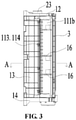
FIG. 3 is a schematic diagram of the wind wheel device shown inFIG. 1 from yet another view; -
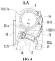
FIG. 4 is a schematic cross-sectional view along the direction A-A inFIG. 3 , but is rotated by 90 degrees counterclockwise relative to orientation ofFIG. 3 , in which a heat generating unit is in a blocking state; -
FIG. 5 is a schematic diagram in the same cross-sectional position asFIG. 4 , in which the heat generating unit is in a non-blocking state; -
FIG. 6 is a schematic diagram of the wind wheel device shown inFIG. 1 from still another view; -
FIG. 7 is enlarged partial diagram of a portion H ofFIG. 2 . - It should be noted that the embodiments and the technical features of the embodiments of the present application may be combined with each other without conflict, and the description of the detailed description should be understood as an explanation of the present application and should not be construed as unduly limiting the present application.
- In the description of the embodiments of the present application, "on", "under" orientation or positional relationship are based on an orientation or positional relationship shown in
FIG. 3 . It should be understood that these orientation terms are intended solely for ease of describing the present application and simplifying the description, and are not intended to indicate or imply that the devices or elements must have a particular orientation, be constructed and operated in a particular orientation. Therefore, these orientation terms are not to be understood as limiting the present application. - For ease of description, in an embodiment of the present application, an example in which the wind wheel device is applied to a fan heater is described.
- Referring to
FIG. 1 to FIG. 6 , an embodiment of the present application provides a wind wheel device including ahousing 1, aheat generating unit 2 and awind wheel 3. Anair duct 11 is formed in thehousing 1, and theair duct 11 includes afirst air duct 111 and a successivesecond air duct 112 connected with thefirst air duct 111. Thewind wheel 3 is arranged in thefirst air duct 111. Theheat generating unit 2 is rotatably arranged in thesecond air duct 112, that is, a direction of airflow in theair duct 11 is a direction from thefirst air duct 111 to the second air duct 112 (the arrow direction inFIG. 4 andFIG. 5 ). Thesecond air duct 112 has anon-blocking area 112b. Theheat generating unit 2 includes a blocking state in which thesecond air duct 112 is blocked and a non-blocking state in which thesecond air duct 112 is not blocked. Referring toFIG. 4 , it will be appreciated that thenon-blocking area 112b can be formed by protruding outwardly from a first side of thesecond air duct 112, and can be integrally molded with thesecond air duct 112, which is simple in process and aesthetic. - Specifically, referring to
FIG. 4 , when theheat generating unit 2 is rotated to an angle in which thesecond air duct 112 is blocked by theheat generating unit 2, theheat generating unit 2 is in the blocking state. In the blocking state, the airflow is driven by thewind wheel 3 to enter into theair duct 11 from thefirst air duct 111, is heated by theheat generating unit 2 to increase the temperature of the airflow, and is discharged from thesecond air duct 112, thereby achieving the function of blowing hot wind of the fan heater. Referring toFIG. 5 , when theheat generating unit 2 is rotated to an angle in which thesecond air duct 112 is not blocked by theheat generating unit 2, theheat generating unit 2 is in the non-blocking state. In the non-blocking state, the airflow is driven by thewind wheel 3 to enter into theair duct 11 from thefirst air duct 111, and to be discharged from thesecond air duct 112, thereby achieving the function of blowing room-temperature wind of the fan heater. - According to the wind wheel device of the embodiment of the present application, the
heat generating unit 2 is rotatably arranged in thesecond air duct 112. Therefore, theheat generating unit 2 only needs to occupy a small space, so that the wind wheel device has a compact structure. Further, when theheat generating unit 2 is in the non-blocking state, theheat generating unit 2 is accommodated in the non-blocking area, so that the airflow can be directly discharged without flowing through theheat generating unit 2. This effectively reduces the wind resistance, and increases the wind quantity and wind speed of the fan heater, so that the performance of the blowing device is good. In an embodiment of the present application, referring toFIG. 5 , when theheat generating unit 2 is in the non-blocking state, a minimum width C between a surface of theheat generating unit 2 away from a first side of thesecond air duct 112 and a second side of thesecond air duct 112 opposite to the first side is greater than or equal to a width f of a tail end of thefirst air duct 111. Therefore, the effective flow area of the airflow from thefirst air duct 111 to thesecond air duct 112 is in an equal or enlarged state, thereby preventing the wind quantity and wind speed in thesecond air duct 112 from changing due to the reduction of the effective flow area. - In an embodiment of the present application, an axis of rotation of the
heat generating unit 2 is parallel to an axis of rotation of thewind wheel 3, so as to prevent theheating element unit 2 from tilting in theair duct 11. In other words, theheating element unit 2 is either completely in the blocking state or completely in the non-blocking state in an axial direction of theheating element unit 2. However, it is impossible that a part of theheating element unit 2 is in the blocking state and the remaining part of theheating element unit 2 is in the non-blocking state. - In an embodiment of the present application, referring to
FIG. 4 andFIG. 5 , a ratio of a width d1 at a head end of thefirst air duct 111 in an airflow direction to a width d2 at a tail end of the first air duct in the airflow direction is between 1.6 and 2, thereby forming a structure with a large inlet and a small outlet. The airflow enters from the head end of the widerfirst air duct 111. When the wind quantity is satisfied, the airflow has a slow flow rate and low noise, and the airflow is driven by thewind wheel 3 to be discharged from the tail end of thefirst air duct 111, so that the wind speed of the fan heater is satisfied. - In an embodiment of the present application, referring to
FIG. 4 andFIG. 5 , thehousing 1 includes aworm tongue 111a and aworm casing 111b spaced apart from each other. Thefirst air duct 111 is formed between theworm tongue 111a and theworm casing 111b. It is not suitable that a spacing E between theworm tongue 111a and an outer edge of thewind wheel 3 is too large or too small. If the spacing E is too large, the airflow enters from thefirst air duct 111, thewind wheel 3 rotates in the clockwise direction inFIG. 4 , and a large part of the airflow in thefirst air duct 111 is carried out of thefirst air duct 111 by thewind wheel 3 from the spacing E, which affects the airflow entering thesecond air duct 112, so that the wind quantity and wind speed are affected. If the spacing E is too small, the requirements for the assembly error of each part of the structure and the sloshing amount of thewind wheel 3 during the rotation of thewind wheel 3 are high, otherwise it is easy to cause interference between theworm tongue 111a and thewind wheel 3 which will generate abnormal sound. In an embodiment of the present application, the spacing E is between 2 mm and 4 mm, so that more airflow flows toward thesecond air duct 112 while ensuring stable performance, thereby increasing the wind quantity and wind speed. - In an embodiment of the present application, referring to
FIG. 4 andFIG. 5 , a spacing D between an inner surface of theworm casing 111b and the outer edge of thewind wheel 3 is gradually increased in the airflow direction, so that the outlet side in the airflow direction is always expanded outward to form a diffusing air duct. Therefore, the static pressure is increased, the wind speed flowing through the wind wheel is improved due to the narrow tube effect, the output efficiency is increased, and finally a large wind quantity and low noise are ensured. With reference toFIG. 4 andFIG. 5 , in order to satisfy the requirement that the spacing E between the inner surface of theworm casing 111b and the outer edge of thewind wheel 3 is gradually increased, a shape of the inner surface of theworm casing 111b may be an involute, and a base circle of the involute conforms to thewind wheel 3. The pattern of the involute is more favorable to the hydrodynamic design performance, so that the airflow can flow more smoothly along the inner surface of theworm casing 111b. - In an embodiment of the present application, referring to
FIG. 1 to FIG. 5 , thehousing 1 includes afirst end plate 12, afirst side plate 13, asecond end plate 14 and asecond side plate 15. Thefirst side plate 13 and thesecond side plate 15 are spaced apart from each other. Thefirst end plate 12 is arranged between a first end of thefirst side plate 13 and a first end of thesecond side plate 15 for connecting the first end of thefirst side plate 13 and the first end of thesecond side plate 15 with each other. Thesecond end plate 14 is arranged between a second end of thefirst side plate 13 and a second end of thesecond side plate 15 for connecting the second end of thefirst side plate 13 and the second end of thesecond side plate 15 with each other. Thefirst end plate 12, thefirst side plate 13, thesecond end plate 14 and thesecond side plate 15 together form theair duct 11. Theheat generating unit 2 is rotatably mounted on thefirst end plate 12 and thesecond end plate 14, and thewind wheel 3 is rotatably mounted on thefirst end plate 12 and thesecond end plate 14, so that the airflow in thefirst air duct 111 is driven to enter into thesecond air duct 112, thereby realizing the function of blowing hot wind and blowing room-temperature wind of the wind wheel device in the fan heater. With reference toFIG. 1 , thefirst side plate 13 includes aworm casing 111b and asub-side plate 112c which are located at the same side of theair duct 11. Theworm casing 111b corresponds to thefirst air duct 111, that is, theworm casing 111b and theworm tongue 111a formfirst air duct 111. Thesub-side plate 112c corresponds to thesecond air duct 112, that is, thesub-side plate 112c and thesecond side plate 15 form thesecond air duct 112. - Specifically, the
worm casing 111b may be separable from thesub-side plate 112c; or theworm casing 111b may be integrally formed with thesub-side plate 112c. When theworm casing 111b is separable from thesub-side plate 112c, theworm casing 111b is detachably connected with thesub-side plate 112c. One of theworm casing 111b and thesub-side plate 112c is formed with a snap 113, and the other one of theworm casing 111b and thesub-side plate 112c is formed with a slot 114. The snap 113 is snapped into the slot 114, that is, theworm casing 111b is engaged with thesub-side plate 112c, so that the structure is reliable and the assembly is simple. It will be appreciated that other means such as screw connection or interference assembly can be used to connect theworm casing 111b and thesub-side plate 112c with each other, which will not be described herein. When theworm casing 111b is integrally formed with thesub-side plate 112c, theworm casing 111b and thesub-side plate 112c can be integrally molded by a mold, which omits the assembly process. - In an embodiment of the present application, referring to
FIG. 2 , thefirst end plate 12 is formed with anopen groove 121, and theopen groove 121 extends to an edge of thefirst end plate 12 and is formed with anopening 122 at the edge of thefirst end plate 12. That is, theopen groove 121 penetrates through an edge of thehousing 1 located at thefirst end plate 12. Theheat generating unit 2 includes a heatgenerating body portion 21 and ashaft portion 22 at one end of the heat generatingbody portion 21. Theshaft portion 22 is capable to be interposed in theopen groove 121 from theopening 122, so that the heat generatingbody portion 21 can be pushed into thesecond air duct 112. - The wind wheel device includes a
driving mechanism 23, and thedriving mechanism 23 is connected with theshaft portion 22 and drives theshaft portion 22, to drive the heat generatingbody portion 21 to rotate in thesecond air duct 112. Specifically, thedriving mechanism 23 drives the heat generatingbody portion 21 to rotate about an axis of rotation of theshaft portion 22. - Specifically, the
driving mechanism 23 can be a motor, which has low cost and stable performance. - In an embodiment of the present application, referring to
FIG. 2 andFIG. 7 , the wind wheel device further includes asleeve 24, and thesleeve 24 is arranged around theshaft portion 22 so as to limit theshaft portion 22 in a circumferential direction of theshaft portion 22. Therefore, theshaft portion 22 is prevented from sloshing in the lateral direction which generates abnormal noise, when theshaft portion 22 is driven by thedriving mechanism 23. A tail end of theopen groove 121 away from theopening 122 is formed with an arc-shapedhole 123. Thesleeve 24 is arranged in the arc-shapedhole 123 and adapted to the arc-shapedhole 123. That is, the outer diameter of thesleeve 24 is approximately equal to the inner diameter of the arc-shapedhole 123, so as to perform better circumferential positioning of thesleeve 24. During assembly, thedriving mechanism 23 is fixedly connected to thefirst end plate 12, so that thedriving mechanism 23 abuts against a side of thesleeve 24 away from the heat generatingbody portion 21, that is, thedriving mechanism 23 abuts against a top side of thesleeve 24. As such, one side of thesleeve 24 is axially limited by thedriving mechanism 23, and the other side ofsleeve 24 is axially limited by the arc-shapedhole 123. Thesleeve 24 can be positioned and mounted without fastening connections such as screws or the like, so that theheat generating unit 2 is fixed to theair duct 11 without screws. On the one hand, the number of parts is reduced, and the quality problems caused by the number of parts can be reduced, on the other hand, the assembly process is simplified and the cost is reduced. Thedriving mechanism 23 includes a power shaft (not shown). The power shaft extends into thesleeve 24, is connected with theshaft portion 22 and drives theshaft portion 22. - Specifically, the
driving mechanism 23 may be fixed to thefirst end plate 12 by a bolt connection. Referring toFIG. 7 , this design requires the addition of thepositioning screw hole 17 to thehousing 1, and theguide post 18 may also be provided to facilitate the bolt connection after thedriving mechanism 23 is positioned, so that assembly is convenient. Of course, thedriving mechanism 23 may be fixed to thefirst end plate 12 by other fixing means such as a snap connection or the like. - In an embodiment of the present application, with reference to
FIG. 7 , in order to facilitate the supporting and positioning of thesleeve 24, the inner wall of the arc-shapedhole 123 is formed with astep surface 124, thesleeve 24 forms ashoulder 241, and theshoulder 241 abuts against thestep surface 124. Thesleeve 24 is supported by thestep surface 124, and a bottom end of thesleeve 24 abuts against thehousing 1, so that a relative rotation between thesleeve 24 and theheat generating unit 2 is prevented, thereby reducing the rotation resistance of theheat generating unit 2. - In an embodiment of the present application, referring to
FIG. 3 andFIG. 5 , thehousing 1 further includes elastic buckles 16. - At least one of the elastic buckles 16 is arranged at an edge of the
first side plate 13; and/or at least one of the elastic buckles 16 is formed at an edge of thesecond side plate 15, so as to facilitate combing the wiring harnesses of the internal components of the blowing device. - A second aspect of an embodiment of the present application provides a blowing device including an enclosure (not shown) and a wind wheel device of any of the above. The wind wheel device is arranged in the enclosure. An air inlet and an air outlet are formed on the enclosure, and the
air duct 11 is in communication with the air inlet and the air outlet. Specifically, thefirst air duct 111 is in communication with the air inlet, and thesecond air duct 112 is in communication with the air outlet. - It will be appreciated that the blowing device may be a cold fan, a fan heater, an air conditioner, or an air purifier, which is not limited herein.
- The various embodiments/implementations provided herein may be combined with each other without conflict.
- What described above are merely preferable embodiments of the present application, and are not intended to limit the present application. Various changes and variations can be made in the present application for those skilled in the art. All modifications, replacements and improvements made within the spirit and principles of the present application should be included within the scope of protection of the present application.
Claims (15)
- A wind wheel device, comprising a housing, a heat generating unit and a wind wheel, an air duct being formed in the housing, the air duct comprising a first air duct and a successive second air duct connected with the first air duct, the wind wheel being arranged in the first air duct, the second air duct having a non-blocking area, the heat generating unit being rotatably arranged in the second air duct, the heat generating unit comprising a blocking state in which the second air duct is blocked and a non-blocking state in which the second air duct is not blocked, wherein the heat generating unit is accommodated in the non-blocking area when the heat generating unit is in the non-blocking state.
- The wind wheel device of claim 1, wherein the non-blocking area is formed by protruding outwardly from a first side of the second air duct.
- The wind wheel device of claim 1, wherein when the heat generating unit is in the non-blocking state, a minimum width between a surface of the heat generating unit away from a first side of the second air duct and a second side of the second air duct opposite to the first side is greater than or equal to a width of a tail end of the first air duct.
- The wind wheel device of claim 1, wherein an axis of rotation of the heat generating unit is parallel to an axis of rotation of the wind wheel.
- The wind wheel device of claim 1, wherein a ratio of a width at a head end of the first air duct in an airflow direction to a width at a tail end of the first air duct in the airflow direction is between 1.6 and 2.
- The wind wheel device of claim 1, wherein the housing comprises a worm tongue and a worm casing spaced apart from each other, the first air duct is formed between the worm tongue and the worm casing, and a spacing between the worm tongue and an outer edge of the wind wheel is between 2 mm and 4 mm.
- The wind wheel device of claim 1, wherein the housing comprises a worm tongue and a worm casing spaced apart from each other, the first air duct is formed between the worm tongue and the worm casing, and a spacing between an inner surface of the worm casing and an outer edge of the wind wheel is gradually increased in an airflow direction.
- The wind wheel device of claim 7, wherein a shape of the inner surface of the worm casing is an involute, and a base circle of the involute conforms to the wind wheel.
- The wind wheel device of claim 1, the housing comprises a first end plate, a first side plate, a second end plate and a second side plate, the first side plate and the second side plate are spaced apart from each other, the first end plate is arranged between a first end of the first side plate and a first end of the second side plate for connecting the first end of the first side plate and the first end of the second side plate with each other, the second end plate is arranged between a second end of the first side plate and a second end of the second side plate for connecting the second end of the first side plate and the second end of the second side plate with each other, the first end plate, the first side plate, the second end plate and the second side plate together form the air duct, the heat generating unit is rotatably mounted on the first end plate and the second end plate, and the wind wheel is rotatably mounted on the first end plate and the second end plate.
- The wind wheel device of claim 9, wherein the first side plate comprises a worm casing and a sub-side plate which are located at the same side of the air duct, the worm casing corresponding to the first air duct, and the sub-side plate corresponding to the second air duct;
the worm casing is separable from the sub-side plate; or the worm casing is integrally formed with the sub-side plate. - The wind wheel device of claim 10, wherein when the worm casing is separable from the sub-side plate, one of the worm casing and the sub-side plate is formed with a snap, and the other one of the worm casing and the sub-side plate is formed with a slot, the snap is snapped into the slot.
- The wind wheel device of claim 9, wherein the first end plate is formed with an open groove, the open groove extending to an edge of the first end plate and being formed with an opening at the edge of the first end plate, the heat generating unit comprising a heat generating body portion and a shaft portion at one end of the heat generating body portion, the shaft portion being capable to be interposed in the open groove from the opening, the wind wheel device comprising a driving mechanism, the driving mechanism being connected with the shaft portion and driving the shaft portion.
- The wind wheel device of claim 12, wherein the wind wheel device further comprises a sleeve, a tail end of the open groove away from the opening being formed with an arc-shaped hole, the sleeve being arranged in the arc-shaped hole and adapted to the arc-shaped hole, the sleeve being arranged around the shaft portion, the driving mechanism comprising a power shaft, the power shaft extending into the sleeve, being connected with the shaft portion and driving the shaft portion.
- The wind wheel device of claim 9, wherein the housing further comprises elastic buckles,
at least one of the elastic buckles is arranged at an edge of the first side plate; and/or at least one of the elastic buckles is formed at an edge of the second side plate. - A blowing device, comprising an enclosure and a wind wheel device according to any one of claims 1 to 14, the wind wheel device being arranged in the enclosure,
an air inlet and an air outlet are formed on the enclosure, and the air duct is in communication with the air inlet and the air outlet.
Applications Claiming Priority (2)
| Application Number | Priority Date | Filing Date | Title |
|---|---|---|---|
| CN201921236063.1U CN210769402U (en) | 2019-08-01 | 2019-08-01 | Wind wheel device and blowing equipment |
| PCT/CN2019/108664 WO2021017144A1 (en) | 2019-08-01 | 2019-09-27 | Wind wheel apparatus and air blowing device |
Publications (2)
| Publication Number | Publication Date |
|---|---|
| EP3961042A1 true EP3961042A1 (en) | 2022-03-02 |
| EP3961042A4 EP3961042A4 (en) | 2022-09-07 |
Family
ID=71063310
Family Applications (1)
| Application Number | Title | Priority Date | Filing Date |
|---|---|---|---|
| EP19939294.5A Pending EP3961042A4 (en) | 2019-08-01 | 2019-09-27 | WIND WHEEL APPARATUS AND AIR BLOWING DEVICE |
Country Status (5)
| Country | Link |
|---|---|
| US (1) | US11867194B2 (en) |
| EP (1) | EP3961042A4 (en) |
| JP (1) | JP2022541501A (en) |
| CN (1) | CN210769402U (en) |
| WO (1) | WO2021017144A1 (en) |
Families Citing this family (3)
| Publication number | Priority date | Publication date | Assignee | Title |
|---|---|---|---|---|
| JP7439806B2 (en) * | 2021-08-30 | 2024-02-28 | 三菱電機株式会社 | Blower |
| CN115750438A (en) * | 2022-12-19 | 2023-03-07 | 重庆一鼓风洞科技有限责任公司 | Single-suction three-dimensional flow impeller assembly for large-scale high-temperature centrifugal fan |
| CN117029122B (en) * | 2023-09-04 | 2026-03-20 | 珠海格力电器股份有限公司 | A portable dehumidifier |
Family Cites Families (20)
| Publication number | Priority date | Publication date | Assignee | Title |
|---|---|---|---|---|
| JPS4851049U (en) * | 1971-10-14 | 1973-07-03 | ||
| DE2208377A1 (en) * | 1972-02-23 | 1973-09-06 | Kurt Dr Ing Zenkner | METHOD FOR REGULATING THE HEATING CAPACITY OF HEATING DEVICES IN MOTOR VEHICLES OR THE SAME, AND DEVICE FOR CARRYING OUT THE METHOD |
| JPS5943697U (en) * | 1982-09-13 | 1984-03-22 | 株式会社東芝 | Air blower |
| JPS60219496A (en) * | 1984-04-17 | 1985-11-02 | Komatsu Ltd | Cross flow fan |
| JPH0810078B2 (en) * | 1990-01-11 | 1996-01-31 | 喜久知工業株式会社 | damper |
| DE19911645A1 (en) * | 1999-03-16 | 2000-09-21 | Volkswagen Ag | Heating device for heating up air flow includes a heat exchanger in various heating positions able to swivel into an air current to be heated up. |
| JP2007210598A (en) * | 2006-01-13 | 2007-08-23 | Denso Corp | Air conditioner |
| JP4537433B2 (en) * | 2007-08-30 | 2010-09-01 | 三菱電機株式会社 | Air conditioner |
| CN201166456Y (en) * | 2008-02-02 | 2008-12-17 | 佛山市富士宝电器科技有限公司 | Drive mechanism of air conditioner fan heating body |
| CN201181069Y (en) * | 2008-03-05 | 2009-01-14 | 美的集团有限公司 | Cold-warm conversion device for cold-warm air conditioning fan |
| CN201241847Y (en) * | 2008-06-06 | 2009-05-20 | 东莞市科达机电设备有限公司 | Fan blower |
| KR20100038571A (en) * | 2008-10-06 | 2010-04-15 | 현대자동차주식회사 | Air conditioning device for vehicles |
| CN101614426A (en) * | 2009-07-22 | 2009-12-30 | 中山市耀升电器制造有限公司 | Cold and warm air automatic conversion device designed on centrifugal air duct |
| JP5369141B2 (en) * | 2011-06-10 | 2013-12-18 | 三菱電機株式会社 | Air conditioner |
| CN204025153U (en) * | 2014-06-09 | 2014-12-17 | 艾美特电器(深圳)有限公司 | A kind of both cooling and heating fan |
| CN104061668B (en) * | 2014-06-17 | 2016-11-09 | 珠海格力电器股份有限公司 | Indoor unit of air conditioner |
| US9493903B2 (en) * | 2014-10-27 | 2016-11-15 | Haier Us Appliance Solutions, Inc. | Impeller assembly for an appliance |
| WO2018137425A1 (en) * | 2017-01-25 | 2018-08-02 | 珠海格力电器股份有限公司 | Base assembly for air conditioner and air conditioner |
| CN208966706U (en) * | 2018-11-13 | 2019-06-11 | 江苏金新空调有限公司 | A kind of blower housing with buckle |
| CN109737505A (en) * | 2018-12-20 | 2019-05-10 | 青岛海尔空调器有限总公司 | Air conditioner |
-
2019
- 2019-08-01 CN CN201921236063.1U patent/CN210769402U/en active Active
- 2019-09-27 US US17/624,075 patent/US11867194B2/en active Active
- 2019-09-27 WO PCT/CN2019/108664 patent/WO2021017144A1/en not_active Ceased
- 2019-09-27 JP JP2022502823A patent/JP2022541501A/en active Pending
- 2019-09-27 EP EP19939294.5A patent/EP3961042A4/en active Pending
Also Published As
| Publication number | Publication date |
|---|---|
| EP3961042A4 (en) | 2022-09-07 |
| CN210769402U (en) | 2020-06-16 |
| US20220356886A1 (en) | 2022-11-10 |
| JP2022541501A (en) | 2022-09-26 |
| US11867194B2 (en) | 2024-01-09 |
| WO2021017144A1 (en) | 2021-02-04 |
Similar Documents
| Publication | Publication Date | Title |
|---|---|---|
| EP3961042A1 (en) | Wind wheel apparatus and air blowing device | |
| CN112303904B (en) | Air duct assembly, wind wheel device and blowing equipment | |
| CN106286327A (en) | Centrifugal blower | |
| JP2016000609A (en) | Wind direction adjusting device | |
| WO2022142376A1 (en) | Fan | |
| CN112984628B (en) | Air outlet component and air conditioner | |
| US6386843B1 (en) | Housing for fan units, and electrical apparatus using a fan unit | |
| CN112469903A (en) | Fan device for motor vehicle | |
| CN114484598A (en) | Air conditioner indoor unit and air conditioner | |
| CN210638118U (en) | Air conditioner | |
| CN112366852A (en) | Motor assembly, air conditioner indoor unit and air conditioner | |
| CN220275120U (en) | hair drying equipment | |
| CN216591971U (en) | an air conditioner | |
| CN213990314U (en) | A motor assembly, an air conditioner indoor unit and an air conditioner | |
| CN216518755U (en) | Fan structure and hand-held fan with hidden fan blades | |
| CN116602492A (en) | hair drying equipment | |
| US7094028B2 (en) | Outlet airflow direction control device | |
| CN115163529A (en) | Air supply structure and air supply device | |
| CN222527784U (en) | Air conditioner | |
| CN223600999U (en) | Hair drier | |
| CN114251823B (en) | Front panel assembly for cabinet air conditioner and air conditioner | |
| CN215949946U (en) | Fan and household appliance | |
| CN223191715U (en) | A duct machine | |
| CN220061894U (en) | Air conditioner indoor unit and air conditioner | |
| CN119573120B (en) | Air conditioner |
Legal Events
| Date | Code | Title | Description |
|---|---|---|---|
| STAA | Information on the status of an ep patent application or granted ep patent |
Free format text: STATUS: THE INTERNATIONAL PUBLICATION HAS BEEN MADE |
|
| PUAI | Public reference made under article 153(3) epc to a published international application that has entered the european phase |
Free format text: ORIGINAL CODE: 0009012 |
|
| STAA | Information on the status of an ep patent application or granted ep patent |
Free format text: STATUS: REQUEST FOR EXAMINATION WAS MADE |
|
| 17P | Request for examination filed |
Effective date: 20211123 |
|
| AK | Designated contracting states |
Kind code of ref document: A1 Designated state(s): AL AT BE BG CH CY CZ DE DK EE ES FI FR GB GR HR HU IE IS IT LI LT LU LV MC MK MT NL NO PL PT RO RS SE SI SK SM TR |
|
| REG | Reference to a national code |
Ref country code: DE Ref legal event code: R079 Free format text: PREVIOUS MAIN CLASS: F04D0025080000 Ipc: F04D0017040000 |
|
| A4 | Supplementary search report drawn up and despatched |
Effective date: 20220809 |
|
| RIC1 | Information provided on ipc code assigned before grant |
Ipc: B60H 1/00 20060101ALI20220803BHEP Ipc: F04D 29/42 20060101ALI20220803BHEP Ipc: F04D 17/04 20060101AFI20220803BHEP |
|
| DAV | Request for validation of the european patent (deleted) | ||
| DAX | Request for extension of the european patent (deleted) | ||
| STAA | Information on the status of an ep patent application or granted ep patent |
Free format text: STATUS: EXAMINATION IS IN PROGRESS |
|
| 17Q | First examination report despatched |
Effective date: 20241009 |