EP3960924A1 - Clothes treatment apparatus - Google Patents
Clothes treatment apparatus Download PDFInfo
- Publication number
- EP3960924A1 EP3960924A1 EP19945153.5A EP19945153A EP3960924A1 EP 3960924 A1 EP3960924 A1 EP 3960924A1 EP 19945153 A EP19945153 A EP 19945153A EP 3960924 A1 EP3960924 A1 EP 3960924A1
- Authority
- EP
- European Patent Office
- Prior art keywords
- drain pipe
- water
- inlet
- treatment apparatus
- pipe
- Prior art date
- Legal status (The legal status is an assumption and is not a legal conclusion. Google has not performed a legal analysis and makes no representation as to the accuracy of the status listed.)
- Granted
Links
Images


Classifications
-
- D—TEXTILES; PAPER
- D06—TREATMENT OF TEXTILES OR THE LIKE; LAUNDERING; FLEXIBLE MATERIALS NOT OTHERWISE PROVIDED FOR
- D06F—LAUNDERING, DRYING, IRONING, PRESSING OR FOLDING TEXTILE ARTICLES
- D06F29/00—Combinations of a washing machine with other separate apparatus in a common frame or the like, e.g. with rinsing apparatus
- D06F29/02—Combinations of a washing machine with other separate apparatus in a common frame or the like, e.g. with rinsing apparatus with liquid-extracting apparatus
-
- D—TEXTILES; PAPER
- D06—TREATMENT OF TEXTILES OR THE LIKE; LAUNDERING; FLEXIBLE MATERIALS NOT OTHERWISE PROVIDED FOR
- D06F—LAUNDERING, DRYING, IRONING, PRESSING OR FOLDING TEXTILE ARTICLES
- D06F29/00—Combinations of a washing machine with other separate apparatus in a common frame or the like, e.g. with rinsing apparatus
- D06F29/005—Combinations of a washing machine with other separate apparatus in a common frame or the like, e.g. with rinsing apparatus the other separate apparatus being a drying appliance
-
- D—TEXTILES; PAPER
- D06—TREATMENT OF TEXTILES OR THE LIKE; LAUNDERING; FLEXIBLE MATERIALS NOT OTHERWISE PROVIDED FOR
- D06F—LAUNDERING, DRYING, IRONING, PRESSING OR FOLDING TEXTILE ARTICLES
- D06F39/00—Details of washing machines not specific to a single type of machines covered by groups D06F9/00 - D06F27/00
- D06F39/08—Liquid supply or discharge arrangements
- D06F39/083—Liquid discharge or recirculation arrangements
- D06F39/085—Arrangements or adaptations of pumps
-
- D—TEXTILES; PAPER
- D06—TREATMENT OF TEXTILES OR THE LIKE; LAUNDERING; FLEXIBLE MATERIALS NOT OTHERWISE PROVIDED FOR
- D06F—LAUNDERING, DRYING, IRONING, PRESSING OR FOLDING TEXTILE ARTICLES
- D06F58/00—Domestic laundry dryers
- D06F58/20—General details of domestic laundry dryers
- D06F58/24—Condensing arrangements
-
- D—TEXTILES; PAPER
- D06—TREATMENT OF TEXTILES OR THE LIKE; LAUNDERING; FLEXIBLE MATERIALS NOT OTHERWISE PROVIDED FOR
- D06F—LAUNDERING, DRYING, IRONING, PRESSING OR FOLDING TEXTILE ARTICLES
- D06F2103/00—Parameters monitored or detected for the control of domestic laundry washing machines, washer-dryers or laundry dryers
- D06F2103/58—Parameters monitored or detected for the control of domestic laundry washing machines, washer-dryers or laundry dryers related to condensation, e.g. condensate water level
-
- D—TEXTILES; PAPER
- D06—TREATMENT OF TEXTILES OR THE LIKE; LAUNDERING; FLEXIBLE MATERIALS NOT OTHERWISE PROVIDED FOR
- D06F—LAUNDERING, DRYING, IRONING, PRESSING OR FOLDING TEXTILE ARTICLES
- D06F2105/00—Systems or parameters controlled or affected by the control systems of washing machines, washer-dryers or laundry dryers
- D06F2105/36—Condensing arrangements, e.g. control of water injection therefor
-
- D—TEXTILES; PAPER
- D06—TREATMENT OF TEXTILES OR THE LIKE; LAUNDERING; FLEXIBLE MATERIALS NOT OTHERWISE PROVIDED FOR
- D06F—LAUNDERING, DRYING, IRONING, PRESSING OR FOLDING TEXTILE ARTICLES
- D06F39/00—Details of washing machines not specific to a single type of machines covered by groups D06F9/00 - D06F27/00
- D06F39/08—Liquid supply or discharge arrangements
- D06F39/083—Liquid discharge or recirculation arrangements
-
- D—TEXTILES; PAPER
- D06—TREATMENT OF TEXTILES OR THE LIKE; LAUNDERING; FLEXIBLE MATERIALS NOT OTHERWISE PROVIDED FOR
- D06F—LAUNDERING, DRYING, IRONING, PRESSING OR FOLDING TEXTILE ARTICLES
- D06F58/00—Domestic laundry dryers
- D06F58/32—Control of operations performed in domestic laundry dryers
- D06F58/34—Control of operations performed in domestic laundry dryers characterised by the purpose or target of the control
- D06F58/36—Control of operational steps, e.g. for optimisation or improvement of operational steps depending on the condition of the laundry
Definitions
- the application relates to the technical field of laundry cleaning, and in particular to a laundry treatment apparatus.
- the combined laundry washer-dryer solves the problem of washing and drying laundry simultaneously, and condensed water in a laundry dryer is discharged through a condensed water drain pipe.
- the condensed water generated in the laundry drying process of the laundry dryer is less, and a pipe diameter of an open drain pipe is also smaller.
- the condensed water drain pipe may not discharge a large amount of water in the laundry dryer in time, which brings a hidden danger to the laundry dryer.
- embodiments of the application are intended to provide a laundry treatment apparatus capable of discharging water in time.
- the embodiment of the application provides a laundry treatment apparatus including a laundry drying device, a first drain pipe, a second drain pipe and a drain pump.
- the laundry drying device is provided with a water accumulation tank.
- An inlet of the first drain pipe is in communication with the water accumulation tank.
- a water outlet of the drain pump is in communication with the second drain pipe, and a water inlet of the drain pump is in communication with the water accumulation tank.
- the laundry treatment apparatus includes a controller configured to control the drain pump to be opened when a water level in the water accumulation tank is higher than a first preset water level, so that water in the water accumulation tank is discharged from the water accumulation tank through the first drain pipe and the second drain pipe.
- the first preset water level is higher than a height of the inlet of the first drain pipe.
- controller is configured to control the drain pump to be opened after the water level in the water accumulation tank reaches the first preset water level for a first preset time.
- the controller is configured to control the drain pump to be closed when the water level in the water accumulation tank is lower than a second preset water level.
- the second preset water level is higher than the height of the inlet of the first drain pipe, and the first preset water level is equal to or higher than the second preset water level.
- the controller is further configured to control the drain pump to be closed or to be remained in an open state according to the water level in the water accumulation tank after the drain pump is opened for a second preset time.
- the inlet of the first drain pipe is located at a lowest position of the water accumulation tank.
- a flow area of the second drain pipe is greater than a flow area of the first drain pipe.
- the laundry treatment apparatus includes a liquid level detecting unit for detecting the water level in the water accumulation tank.
- the liquid level detecting unit is electrically connected with the controller.
- the controller is configured to control the drain pump to be opened or to be closed according to a detection result of the liquid level detecting unit.
- the laundry treatment apparatus includes a washing device, a third drain pipe and a main drain pipe.
- the washing device is arranged below the laundry drying device. Water in the washing device is in communication with the main drain pipe through the third drain pipe.
- the first drain pipe, the second drain pipe and the third drain pipe are in communication with the main drain pipe.
- the laundry treatment apparatus includes a multi-channel pipe.
- the multi-channel pipe includes a first inlet connected with the first drain pipe, a second inlet connected with the second drain pipe, a third inlet connected with the third drain pipe, and a main outlet connected with the main drain pipe.
- each of a height of the first inlet and a height of the second inlet is higher than a height of the third inlet.
- the multi-channel pipe is located at an edge of a top of the washing device.
- the multi-channel pipe includes a pipe body and a partition plate arranged in the pipe body.
- the partition plate divides a space in the pipe body into a first flow channel and a second flow channel.
- the third inlet forms an inlet of the first flow channel, and the first inlet and the second inlet form an inlet of the second flow channel.
- the partition plate extends to an end of the pipe body connected with the main drain pipe.
- a flow area of the first flow channel is greater than or equal to a flow area of the third drain pipe.
- the laundry treatment apparatus of the embodiment of the application is provided with the drain pump and the second drain pipe, and the drain pump has an emergency standby function.
- the laundry drying device enables functions such as cylinder self-cleaning and the like, a large amount of cleaning water enters the water accumulation tank, and the first drain pipe may not discharge the water in the water accumulation tank in time, which may cause the water level in the water accumulation tank to continuously rise.
- a water intake faucet on the laundry drying device fails, the water flow of the water intake faucet continuously enters the laundry drying device. If the water flow is not discharged in time, the water flow in the laundry drying device may soak electrical components, which causes the electrical failure of the laundry treatment apparatus, and the water flow in the laundry drying device also overflows into the indoor space.
- the drain pump and the second drain pipe can discharge the water in the water accumulation tank in time, thereby improving the drainage performance of the laundry drying device.
- orientations or positional relationships are based on an orientations or positional relationships shown in FIG. 1 . It should be understood that these orientation terms are intended solely for ease of describing the application and simplifying the description, and are not intended to indicate or imply that the devices or elements must have a particular orientation, be constructed and operated in a particular orientation. Therefore, these orientation terms are not to be understood as limiting the application.
- a flow area refers to the cross-sectional area of fluid passing through the pipe body.
- an embodiment of the application provides a laundry treatment apparatus including a laundry drying device 10, a first drain pipe 31, a second drain pipe 32 and a drain pump 36.
- the laundry drying device 10 is provided with a water accumulation tank 10a, the water accumulation tank 10a is configured for accumulating condensed water generated in the laundry drying process, or for accumulating cleaning water generated when the laundry drying device 10 enables the cylinder self-cleaning mode, and the like.
- An inlet of the first drain pipe 31 is in communication with the water accumulation tank 10a, and the first drain pipe 31 is in a normally open state.
- the water accumulation tank 10a can always discharge the water through the first drain pipe 31 as long as a water level in the water accumulation tank 10a is higher than a height of the inlet of the first drain pipe 31.
- a water outlet of the drain pump 36 is in communication with the second drain pipe 32, and a water inlet of the drain pump 36 is in communication with the water accumulation tank 10a.
- the drain pump 36 has an emergency standby function.
- the laundry drying device 10 enables functions such as cylinder self-cleaning and the like, a large amount of cleaning water enters the water accumulation tank 10a, and the first drain pipe 31 may not discharge the water in the water accumulation tank 10a in time, which may cause the water level in the water accumulation tank 10a to continuously rise.
- a water intake faucet on the laundry drying device fails, the water flow of the water intake faucet continuously enters the laundry drying device. If the water flow is not discharged in time, the water flow in the laundry drying device may soak electrical components, which causes the electrical failure of the laundry treatment apparatus, and the water flow in the laundry drying device also overflows into the indoor space.
- the drain pump 36 and the second drain pipe 32 can discharge the water in the water accumulation tank 10a in time, thereby improving the drainage performance of the laundry drying device.
- the drain pump 36 may be in an open state all the time or may be selectively opened according to a height of the water level.
- the laundry treatment apparatus includes a controller configured to control the drain pump 36 to be opened when the water level in the water accumulation tank 10a is higher than a first preset water level, so that water in the water accumulation tank 10a is discharged from the water accumulation tank 10a through the first drain pipe 31 and the second drain pipe 32.
- the first preset water level is higher than a height of the inlet of the first drain pipe 31. That is, when the water level in the water accumulation tank 10a is lower than the first preset water level, it means that the water level in the water accumulation tank 10a has not reached a warning water level.
- the drainage requirement for the water accumulation tank 10a may be satisfied through the first drain pipe 31, and the drain pump 36 is in a close state, so that the energy can be saved and the consumption can also be reduced, and unnecessary working noise generated by the drain pump 36 can be avoided.
- the controller is configured to control the drain pump 36 to be opened, to forcibly discharge the water through the drain pump 36 and the second drain pipe 32.
- the controller may be configured to control the drain pump 36 to be opened while the water level in the water accumulation tank 10a reaches the first preset water level. That is, as long as the controller obtains information that the water level in the water accumulation tank 10a reaches the first preset water level, the controller is configured to control the drain pump 36 to be opened.
- the controller may further be configured to control the drain pump 36 to be opened after the water level in the water accumulation tank 10a reaches the first preset water level for a first preset time. That is, when the controller obtains information that the water level in the water accumulation tank 10a reaches the first preset water level, and after the water level in the water accumulation tank 10a is higher than or at the first preset water level for the first preset time, the controller is configured to control the drain pump 36 to be opened.
- the first preset time may be set at a reasonable time, for example, 3 seconds, 5 seconds, etc. In this way, it is possible to effectively prevent the controller from misjudging, and to avoid the drain pump 36 from frequently starting and stopping.
- the controller is further configured to control the drain pump 36 to be closed when the water level in the water accumulation tank 10a is lower than a second preset water level.
- the second preset water level is higher than the height of the inlet of the first drain pipe 31, and the first preset water level is equal to or higher than the second preset water level. That is, the first preset water level may be the same as or different from the second preset water level.
- the controller is configured to control the drain pump 36 to be opened when the water level in the water accumulation tank 10a is higher than the first preset water level. At this time, the water in the water accumulation tank 10a is discharged through the first drain pipe 31 and the second drain pipe 32, so that the water level in the water accumulation tank 10a falls.
- the controller may be configured to control the drain pump 36 to be closed, so that the water in the water accumulation tank 10a is discharged through the first drain pipe 31. In this way, it is possible to ensure the normal use of the laundry drying device 10, and to save energy and reduce consumption.
- the controller is configured to control the drain pump 36 to be closed or to be remained in the open state according to the water level in the water accumulation tank 10a after the drain pump 36 is opened for a second preset time.
- the second preset time is a single operation cycle of the drain pump 36, for example, 30 seconds, 35 seconds, etc. Specifically, when the controller is configured to control the drain pump 36 to be opened and the timing is started, and when the drain pump 36 is in the open state for the second preset time, the controller obtains the water level in the water accumulation tank 10a again.
- the drain pump 36 continues to operate for another cycle, i.e., for the second preset time. If the water level is lower than the second preset water level, the controller is configured to control the drain pump 36 to be closed. During one operation cycle of the drain pump 36, regardless of whether the water level is lower than the second preset water level, the drain pump 36 is in the open state until one operation cycle of the drain pump 36 ends up.
- the laundry treatment apparatus includes a liquid level detecting unit for detecting the water level in the water accumulation tank 10a.
- the liquid level detecting unit is electrically connected with the controller.
- the controller is configured to control the drain pump 36 to be opened or to be closed according to a detection result of the liquid level detecting unit.
- the specific type of the liquid level detecting unit is not limited, and the liquid level detecting unit may be of a contact type that needs to be in contact with liquid, for example, a single-flange static pressure transmitter, a double-flange differential pressure liquid level transmitter, a floating ball liquid level transmitter, a magnetic liquid level transmitter, an input liquid level transmitter, an electric inner floating ball liquid level transmitter, an electric float liquid level transmitter, a capacitive liquid level transmitter, a magnetostrictive liquid level transmitter, a servo liquid level transmitter, etc.
- the liquid level detecting unit may also be of a non-contact type that does not need to be in contact with the liquid, for example, an ultrasonic liquid level transmitter, a radar liquid level transmitter, etc.
- the inlet of the first drain pipe 31 is located at a lowest position of the water accumulation tank 10a, so that the water flow in the water accumulation tank 10a can be substantially completely discharged through the first drain pipe 31 under the action of its own gravity.
- a flow area of the second drain pipe 32 is greater than a flow area of the first drain pipe 31, so that the second drain pipe 32 can have a greater flow capacity during emergency drainage.
- the laundry treatment apparatus of an embodiment of the application may be a separate laundry dryer, i.e., only having a laundry drying function, or may be a combined laundry washer-dryer, i.e., including the laundry drying device 10 that performs the laundry drying function and a washing device 20 that performs a washing function, and the laundry drying device 10 and the washing device 20 are independent from each other.
- the laundry treatment apparatus is the combined laundry washer-dryer.
- the laundry treatment apparatus includes the washing device 20, a third drain pipe 33 and a main drain pipe 35.
- the washing device 20 is arranged below the laundry drying device 10, so that the overall structural layout of the laundry treatment apparatus is more reasonable.
- the washing device 20 may have a large amount of water during the washing process, which greatly increases a weight of the washing device 20. Therefore, the washing device 20 is arranged below the laundry drying device 10, so that the laundry drying device 10 does not need to bear the weight of the washing device 20.
- the stress on the laundry drying device 10 can be reduced, and on the other hand, the washing device 20 with a relatively heavy weight is arranged below the laundry drying device 10, so that the stability of the laundry treatment apparatus can be increased.
- Water in the washing device 20 is in communication with the main drain pipe 35 through the third drain pipe 33.
- the first drain pipe 31, the second drain pipe 32 and the third drain pipe 33 are in communication with the main drain pipe 35. That is, water in the first drain pipe 31, the second drain pipe 32 and the third drain pipe 33 is collected into the main drain pipe 35, and is discharged from the laundry treatment apparatus through the main drain pipe 35, so that the number of drain ports of the laundry treatment apparatus on the outer surface can be reduced, centralized drainage can be facilitated, and centralized pipe distribution in the laundry treatment apparatus can be facilitated.
- the washing device 20 may be in an upper drainage mode or a lower drainage mode. In order to facilitate centralized pipe distribution, in an embodiment of the application, the washing device 20 adopts the upper drainage mode.
- the laundry treatment apparatus includes a multi-channel pipe 34.
- the multi-channel pipe 34 includes a first inlet 34a connected with the first drain pipe 31, a second inlet 34b connected with the second drain pipe 32, a third inlet 34c connected with the third drain pipe 33, and a main outlet 34d connected with the main drain pipe 35.
- the multi-channel pipe 34 serves as a transitional connection to facilitate the transitional connection of the first drain pipe 31, the second drain pipe 32, the third drain pipe 33 and the main drain pipe 35.
- the multi-channel pipe 34 may be a four-channel pipe, a five-channel pipe, or other pipe with more channels.
- a portion of the ports of the multi-channel pipe is closed, leaving only four ports as the first inlet 34a, the second inlet 34b, the third inlet 34c and the main outlet 34d, respectively.
- each of a height of the first inlet 34a and a height of the second inlet 34b is higher than a height of the third inlet 34c, so that there is a certain height difference between the water flow from the third drain pipe 33 and the first inlet 34a and the second inlet 34b, which increases the resistance of the water flow from the third drain port into the laundry drying device 10 through the first inlet 34a or the second inlet 34b, and reduces the possibility of the water flow in the third drain pipe 33 flowing backward into the laundry drying device 10.
- the multi-channel pipe includes a pipe body 341 and a partition plate 342 arranged in the pipe body 341.
- the first inlet 34a, the second inlet 34b, the third inlet 34c and the main outlet 34d are formed on the pipe body 341, and the liquid is circulated inside the pipe body 341.
- the partition plate 342 divides a space in the pipe body 341 into a first flow channel 34' and a second flow channel 34".
- the third inlet 34c forms an inlet of the first flow channel 34', and the first inlet 34a and the second inlet 34b form an inlet of the second flow channel 34".
- the partition plate 342 separates the water flow from the third drain pipe 33 from the water flow from the first drain pipe 31 and the second drain pipe 32, and the first flow channel 34' and the second flow channel 34" converge at the end of the partition plate 342, which increases the height difference between the convergence and the first inlet 34a and the second inlet 34b, further increases the resistance of the water flow in the third drain pipe 33 flowing backward into the laundry drying device 10 through the first inlet 34a or the second inlet 34b, and further reduces the possibility of the water flow in the third drain pipe 33 flowing backward into the laundry drying device 10.
- the partition plate 342 extends to an end of the pipe body 341 connected with the main drain pipe 35. That is, the extension length of the partition plate 342 is extended as much as possible, so as to increase the height difference between the convergence and the first inlet 34a and the second inlet 34b as much as possible.
- the amount of drainage in the washing device 20 is relatively large, and the shape of the partition plate 342 remains arc-shaped, so that the cross-sectional shape of the first flow channel 34' is substantially circular, so as to increase the flow capacity of the first flow channel 34' and reduce the water flow resistance of the first flow channel 34' as much as possible.
- a flow area of the first flow channel 34' is greater than or equal to a flow area of the third drain pipe 33. In this way, after the water flow flows from the third drain pipe 33 into the first flow channel 34', the first flow channel 34' does not form a throttling effect, so that the water flow can smoothly enter the main drain pipe 35 through the multi-channel pipe 34.
- the multi-channel pipe 34 is located at the edge of the top of the washing device 20, for example, at the edge of the rear side of the washing device 20 away from the user.
- the upper drainage requirement for the third drain pipe 33 can be satisfied, and on the other hand, the multi-channel pipe 34 is located as much as possible at the junction of the washing device 20 and the laundry drying device 10 in a height direction, and the lengths of the first drain pipe 31 and the second drain pipe 32 are shortened as much as possible, so that centralized pipe distribution can be facilitated, and the pipe distribution structure of the laundry treatment apparatus can be more compact.
Landscapes
- Engineering & Computer Science (AREA)
- Textile Engineering (AREA)
- Detail Structures Of Washing Machines And Dryers (AREA)
- Accessory Of Washing/Drying Machine, Commercial Washing/Drying Machine, Other Washing/Drying Machine (AREA)
- Drying Of Solid Materials (AREA)
- Control Of Washing Machine And Dryer (AREA)
Abstract
Description
- This application is based upon and claims the priority to
Chinese Patent Application No. 201910854432.1, filed on September 10, 2019 - The application relates to the technical field of laundry cleaning, and in particular to a laundry treatment apparatus.
- Taking a combined laundry washer-dryer as an example, the combined laundry washer-dryer solves the problem of washing and drying laundry simultaneously, and condensed water in a laundry dryer is discharged through a condensed water drain pipe. Generally, the condensed water generated in the laundry drying process of the laundry dryer is less, and a pipe diameter of an open drain pipe is also smaller. When the laundry dryer is equipped with functions such as cylinder self-cleaning and the like, the condensed water drain pipe may not discharge a large amount of water in the laundry dryer in time, which brings a hidden danger to the laundry dryer.
- In view of the above, embodiments of the application are intended to provide a laundry treatment apparatus capable of discharging water in time.
- To achieve the above object, the embodiment of the application provides a laundry treatment apparatus including a laundry drying device, a first drain pipe, a second drain pipe and a drain pump. The laundry drying device is provided with a water accumulation tank. An inlet of the first drain pipe is in communication with the water accumulation tank. A water outlet of the drain pump is in communication with the second drain pipe, and a water inlet of the drain pump is in communication with the water accumulation tank.
- Further, the laundry treatment apparatus includes a controller configured to control the drain pump to be opened when a water level in the water accumulation tank is higher than a first preset water level, so that water in the water accumulation tank is discharged from the water accumulation tank through the first drain pipe and the second drain pipe. Herein, the first preset water level is higher than a height of the inlet of the first drain pipe.
- Further, the controller is configured to control the drain pump to be opened after the water level in the water accumulation tank reaches the first preset water level for a first preset time.
- Further, the controller is configured to control the drain pump to be closed when the water level in the water accumulation tank is lower than a second preset water level. Herein, the second preset water level is higher than the height of the inlet of the first drain pipe, and the first preset water level is equal to or higher than the second preset water level.
- The controller is further configured to control the drain pump to be closed or to be remained in an open state according to the water level in the water accumulation tank after the drain pump is opened for a second preset time.
- Further, the inlet of the first drain pipe is located at a lowest position of the water accumulation tank.
- Further, a flow area of the second drain pipe is greater than a flow area of the first drain pipe.
- Further, the laundry treatment apparatus includes a liquid level detecting unit for detecting the water level in the water accumulation tank. The liquid level detecting unit is electrically connected with the controller. The controller is configured to control the drain pump to be opened or to be closed according to a detection result of the liquid level detecting unit.
- Further, the laundry treatment apparatus includes a washing device, a third drain pipe and a main drain pipe. The washing device is arranged below the laundry drying device. Water in the washing device is in communication with the main drain pipe through the third drain pipe. The first drain pipe, the second drain pipe and the third drain pipe are in communication with the main drain pipe.
- Further, the laundry treatment apparatus includes a multi-channel pipe. The multi-channel pipe includes a first inlet connected with the first drain pipe, a second inlet connected with the second drain pipe, a third inlet connected with the third drain pipe, and a main outlet connected with the main drain pipe.
- Further, each of a height of the first inlet and a height of the second inlet is higher than a height of the third inlet.
- Further, the multi-channel pipe is located at an edge of a top of the washing device.
- Further, the multi-channel pipe includes a pipe body and a partition plate arranged in the pipe body. The partition plate divides a space in the pipe body into a first flow channel and a second flow channel. The third inlet forms an inlet of the first flow channel, and the first inlet and the second inlet form an inlet of the second flow channel.
- Further, the partition plate extends to an end of the pipe body connected with the main drain pipe.
- Further, a flow area of the first flow channel is greater than or equal to a flow area of the third drain pipe.
- The laundry treatment apparatus of the embodiment of the application is provided with the drain pump and the second drain pipe, and the drain pump has an emergency standby function. When the laundry drying device enables functions such as cylinder self-cleaning and the like, a large amount of cleaning water enters the water accumulation tank, and the first drain pipe may not discharge the water in the water accumulation tank in time, which may cause the water level in the water accumulation tank to continuously rise. Or, when a water intake faucet on the laundry drying device fails, the water flow of the water intake faucet continuously enters the laundry drying device. If the water flow is not discharged in time, the water flow in the laundry drying device may soak electrical components, which causes the electrical failure of the laundry treatment apparatus, and the water flow in the laundry drying device also overflows into the indoor space. In the embodiment of the application, when the water level in the water accumulation tank rises, the drain pump and the second drain pipe can discharge the water in the water accumulation tank in time, thereby improving the drainage performance of the laundry drying device.
-
-
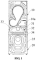
FIG. 1 is a schematic diagram of a laundry treatment apparatus according to an embodiment of the application, in which a part of a decorative housing of the laundry treatment apparatus is omitted; -
FIG. 2 is a partial cross-sectional view of the laundry treatment apparatus shown inFIG. 1 ; -
FIG. 3 is a schematic diagram of a multi-channel pipe according to an embodiment of the application; -
FIG. 4 is a cross-sectional view of the multi-channel pipe shown inFIG. 3 . - It should be noted that the embodiments and the technical features of the embodiments of the application may be combined with each other without conflict, and the description of the detailed description should be understood as an explanation of the application and should not be construed as unduly limiting the application.
- In the description of the application, "upper", "lower", "left", "right", "front" and "rear" orientations or positional relationships are based on an orientations or positional relationships shown in
FIG. 1 . It should be understood that these orientation terms are intended solely for ease of describing the application and simplifying the description, and are not intended to indicate or imply that the devices or elements must have a particular orientation, be constructed and operated in a particular orientation. Therefore, these orientation terms are not to be understood as limiting the application. - In an embodiment of the application, a flow area refers to the cross-sectional area of fluid passing through the pipe body.
- Referring to
FIG. 1 andFIG. 2 , an embodiment of the application provides a laundry treatment apparatus including alaundry drying device 10, afirst drain pipe 31, asecond drain pipe 32 and adrain pump 36. Thelaundry drying device 10 is provided with awater accumulation tank 10a, thewater accumulation tank 10a is configured for accumulating condensed water generated in the laundry drying process, or for accumulating cleaning water generated when thelaundry drying device 10 enables the cylinder self-cleaning mode, and the like. An inlet of thefirst drain pipe 31 is in communication with thewater accumulation tank 10a, and thefirst drain pipe 31 is in a normally open state. Thewater accumulation tank 10a can always discharge the water through thefirst drain pipe 31 as long as a water level in thewater accumulation tank 10a is higher than a height of the inlet of thefirst drain pipe 31. A water outlet of thedrain pump 36 is in communication with thesecond drain pipe 32, and a water inlet of thedrain pump 36 is in communication with thewater accumulation tank 10a. - According to the laundry treatment apparatus of the embodiment of the application, the
drain pump 36 has an emergency standby function. When thelaundry drying device 10 enables functions such as cylinder self-cleaning and the like, a large amount of cleaning water enters thewater accumulation tank 10a, and thefirst drain pipe 31 may not discharge the water in thewater accumulation tank 10a in time, which may cause the water level in thewater accumulation tank 10a to continuously rise. Or, when a water intake faucet on the laundry drying device fails, the water flow of the water intake faucet continuously enters the laundry drying device. If the water flow is not discharged in time, the water flow in the laundry drying device may soak electrical components, which causes the electrical failure of the laundry treatment apparatus, and the water flow in the laundry drying device also overflows into the indoor space. In the embodiment of the application, when the water level in thewater accumulation tank 10a rises, thedrain pump 36 and thesecond drain pipe 32 can discharge the water in thewater accumulation tank 10a in time, thereby improving the drainage performance of the laundry drying device. - The
drain pump 36 may be in an open state all the time or may be selectively opened according to a height of the water level. In the embodiment of the application, the laundry treatment apparatus includes a controller configured to control thedrain pump 36 to be opened when the water level in thewater accumulation tank 10a is higher than a first preset water level, so that water in thewater accumulation tank 10a is discharged from thewater accumulation tank 10a through thefirst drain pipe 31 and thesecond drain pipe 32. Herein, the first preset water level is higher than a height of the inlet of thefirst drain pipe 31. That is, when the water level in thewater accumulation tank 10a is lower than the first preset water level, it means that the water level in thewater accumulation tank 10a has not reached a warning water level. At this time, the drainage requirement for thewater accumulation tank 10a may be satisfied through thefirst drain pipe 31, and thedrain pump 36 is in a close state, so that the energy can be saved and the consumption can also be reduced, and unnecessary working noise generated by thedrain pump 36 can be avoided. When the water level in thewater accumulation tank 10a reaches or exceeds the first preset water level, it means that the water level in thewater accumulation tank 10a has reached the warning water level, and the drainage requirement for thewater accumulation tank 10a may not be satisfied through thefirst drain pipe 31. At this time, the controller is configured to control thedrain pump 36 to be opened, to forcibly discharge the water through thedrain pump 36 and thesecond drain pipe 32. - The controller may be configured to control the
drain pump 36 to be opened while the water level in thewater accumulation tank 10a reaches the first preset water level. That is, as long as the controller obtains information that the water level in thewater accumulation tank 10a reaches the first preset water level, the controller is configured to control thedrain pump 36 to be opened. - It will be appreciated that the controller may further be configured to control the
drain pump 36 to be opened after the water level in thewater accumulation tank 10a reaches the first preset water level for a first preset time. That is, when the controller obtains information that the water level in thewater accumulation tank 10a reaches the first preset water level, and after the water level in thewater accumulation tank 10a is higher than or at the first preset water level for the first preset time, the controller is configured to control thedrain pump 36 to be opened. The first preset time may be set at a reasonable time, for example, 3 seconds, 5 seconds, etc. In this way, it is possible to effectively prevent the controller from misjudging, and to avoid thedrain pump 36 from frequently starting and stopping. - In an embodiment, the controller is further configured to control the
drain pump 36 to be closed when the water level in thewater accumulation tank 10a is lower than a second preset water level. Herein, the second preset water level is higher than the height of the inlet of thefirst drain pipe 31, and the first preset water level is equal to or higher than the second preset water level. That is, the first preset water level may be the same as or different from the second preset water level. Specifically, the controller is configured to control thedrain pump 36 to be opened when the water level in thewater accumulation tank 10a is higher than the first preset water level. At this time, the water in thewater accumulation tank 10a is discharged through thefirst drain pipe 31 and thesecond drain pipe 32, so that the water level in thewater accumulation tank 10a falls. When the water level falls to the second preset water level, the controller may be configured to control thedrain pump 36 to be closed, so that the water in thewater accumulation tank 10a is discharged through thefirst drain pipe 31. In this way, it is possible to ensure the normal use of thelaundry drying device 10, and to save energy and reduce consumption. - In order to avoid the
drain pump 36 from frequently starting and stopping and to prevent the controller from misjudging, in an embodiment of the application, the controller is configured to control thedrain pump 36 to be closed or to be remained in the open state according to the water level in thewater accumulation tank 10a after thedrain pump 36 is opened for a second preset time. The second preset time is a single operation cycle of thedrain pump 36, for example, 30 seconds, 35 seconds, etc. Specifically, when the controller is configured to control thedrain pump 36 to be opened and the timing is started, and when thedrain pump 36 is in the open state for the second preset time, the controller obtains the water level in thewater accumulation tank 10a again. If the water level is higher than or equal to the second preset water level, thedrain pump 36 continues to operate for another cycle, i.e., for the second preset time. If the water level is lower than the second preset water level, the controller is configured to control thedrain pump 36 to be closed. During one operation cycle of thedrain pump 36, regardless of whether the water level is lower than the second preset water level, thedrain pump 36 is in the open state until one operation cycle of thedrain pump 36 ends up. - In order to facilitate the detection of the water level in the
water accumulation tank 10a, in an embodiment, the laundry treatment apparatus includes a liquid level detecting unit for detecting the water level in thewater accumulation tank 10a. The liquid level detecting unit is electrically connected with the controller. The controller is configured to control thedrain pump 36 to be opened or to be closed according to a detection result of the liquid level detecting unit. The specific type of the liquid level detecting unit is not limited, and the liquid level detecting unit may be of a contact type that needs to be in contact with liquid, for example, a single-flange static pressure transmitter, a double-flange differential pressure liquid level transmitter, a floating ball liquid level transmitter, a magnetic liquid level transmitter, an input liquid level transmitter, an electric inner floating ball liquid level transmitter, an electric float liquid level transmitter, a capacitive liquid level transmitter, a magnetostrictive liquid level transmitter, a servo liquid level transmitter, etc. The liquid level detecting unit may also be of a non-contact type that does not need to be in contact with the liquid, for example, an ultrasonic liquid level transmitter, a radar liquid level transmitter, etc. - In order to facilitate the
first drain pipe 31 to discharge almost all the water in thewater accumulation tank 10a, in an embodiment of the application, the inlet of thefirst drain pipe 31 is located at a lowest position of thewater accumulation tank 10a, so that the water flow in thewater accumulation tank 10a can be substantially completely discharged through thefirst drain pipe 31 under the action of its own gravity. - It will be appreciated that a flow area of the
second drain pipe 32 is greater than a flow area of thefirst drain pipe 31, so that thesecond drain pipe 32 can have a greater flow capacity during emergency drainage. - The laundry treatment apparatus of an embodiment of the application may be a separate laundry dryer, i.e., only having a laundry drying function, or may be a combined laundry washer-dryer, i.e., including the
laundry drying device 10 that performs the laundry drying function and awashing device 20 that performs a washing function, and thelaundry drying device 10 and thewashing device 20 are independent from each other. - In the embodiment of the application, the laundry treatment apparatus is the combined laundry washer-dryer. Specifically, with reference to
FIG. 1 andFIG. 2 , the laundry treatment apparatus includes thewashing device 20, athird drain pipe 33 and amain drain pipe 35. Thewashing device 20 is arranged below thelaundry drying device 10, so that the overall structural layout of the laundry treatment apparatus is more reasonable. For example, thewashing device 20 may have a large amount of water during the washing process, which greatly increases a weight of thewashing device 20. Therefore, thewashing device 20 is arranged below thelaundry drying device 10, so that thelaundry drying device 10 does not need to bear the weight of thewashing device 20. On the one hand, the stress on thelaundry drying device 10 can be reduced, and on the other hand, thewashing device 20 with a relatively heavy weight is arranged below thelaundry drying device 10, so that the stability of the laundry treatment apparatus can be increased. - Water in the
washing device 20 is in communication with themain drain pipe 35 through thethird drain pipe 33. Thefirst drain pipe 31, thesecond drain pipe 32 and thethird drain pipe 33 are in communication with themain drain pipe 35. That is, water in thefirst drain pipe 31, thesecond drain pipe 32 and thethird drain pipe 33 is collected into themain drain pipe 35, and is discharged from the laundry treatment apparatus through themain drain pipe 35, so that the number of drain ports of the laundry treatment apparatus on the outer surface can be reduced, centralized drainage can be facilitated, and centralized pipe distribution in the laundry treatment apparatus can be facilitated. - The
washing device 20 may be in an upper drainage mode or a lower drainage mode. In order to facilitate centralized pipe distribution, in an embodiment of the application, thewashing device 20 adopts the upper drainage mode. - In an embodiment, referring to
FIG. 3 andFIG. 4 , the laundry treatment apparatus includes amulti-channel pipe 34. Themulti-channel pipe 34 includes afirst inlet 34a connected with thefirst drain pipe 31, asecond inlet 34b connected with thesecond drain pipe 32, athird inlet 34c connected with thethird drain pipe 33, and amain outlet 34d connected with the main drain pipe 35.Themulti-channel pipe 34 serves as a transitional connection to facilitate the transitional connection of thefirst drain pipe 31, thesecond drain pipe 32, thethird drain pipe 33 and themain drain pipe 35. - The
multi-channel pipe 34 may be a four-channel pipe, a five-channel pipe, or other pipe with more channels. Herein, a portion of the ports of the multi-channel pipe is closed, leaving only four ports as thefirst inlet 34a, thesecond inlet 34b, thethird inlet 34c and themain outlet 34d, respectively. - Since a water pressure in the
third drain pipe 33 is relatively high, in order to prevent the water in thethird drain pipe 33 from flowing backward into thelaundry drying device 10, in an embodiment of the application, referring toFIG. 3 andFIG. 4 , each of a height of thefirst inlet 34a and a height of thesecond inlet 34b is higher than a height of thethird inlet 34c, so that there is a certain height difference between the water flow from thethird drain pipe 33 and thefirst inlet 34a and thesecond inlet 34b, which increases the resistance of the water flow from the third drain port into thelaundry drying device 10 through thefirst inlet 34a or thesecond inlet 34b, and reduces the possibility of the water flow in thethird drain pipe 33 flowing backward into thelaundry drying device 10. - In an embodiment, referring to
FIG. 4 , the multi-channel pipe includes apipe body 341 and apartition plate 342 arranged in thepipe body 341. Thefirst inlet 34a, thesecond inlet 34b, thethird inlet 34c and themain outlet 34d are formed on thepipe body 341, and the liquid is circulated inside thepipe body 341. Thepartition plate 342 divides a space in thepipe body 341 into a first flow channel 34' and asecond flow channel 34". Thethird inlet 34c forms an inlet of the first flow channel 34', and thefirst inlet 34a and thesecond inlet 34b form an inlet of thesecond flow channel 34". That is, thepartition plate 342 separates the water flow from thethird drain pipe 33 from the water flow from thefirst drain pipe 31 and thesecond drain pipe 32, and the first flow channel 34' and thesecond flow channel 34" converge at the end of thepartition plate 342, which increases the height difference between the convergence and thefirst inlet 34a and thesecond inlet 34b, further increases the resistance of the water flow in thethird drain pipe 33 flowing backward into thelaundry drying device 10 through thefirst inlet 34a or thesecond inlet 34b, and further reduces the possibility of the water flow in thethird drain pipe 33 flowing backward into thelaundry drying device 10. - In an embodiment, the
partition plate 342 extends to an end of thepipe body 341 connected with themain drain pipe 35. That is, the extension length of thepartition plate 342 is extended as much as possible, so as to increase the height difference between the convergence and thefirst inlet 34a and thesecond inlet 34b as much as possible. - In an embodiment, the amount of drainage in the
washing device 20 is relatively large, and the shape of thepartition plate 342 remains arc-shaped, so that the cross-sectional shape of the first flow channel 34' is substantially circular, so as to increase the flow capacity of the first flow channel 34' and reduce the water flow resistance of the first flow channel 34' as much as possible. - In an embodiment, a flow area of the first flow channel 34' is greater than or equal to a flow area of the
third drain pipe 33. In this way, after the water flow flows from thethird drain pipe 33 into the first flow channel 34', the first flow channel 34' does not form a throttling effect, so that the water flow can smoothly enter themain drain pipe 35 through themulti-channel pipe 34. - In an embodiment, the
multi-channel pipe 34 is located at the edge of the top of thewashing device 20, for example, at the edge of the rear side of thewashing device 20 away from the user. On the one hand, the upper drainage requirement for thethird drain pipe 33 can be satisfied, and on the other hand, themulti-channel pipe 34 is located as much as possible at the junction of thewashing device 20 and thelaundry drying device 10 in a height direction, and the lengths of thefirst drain pipe 31 and thesecond drain pipe 32 are shortened as much as possible, so that centralized pipe distribution can be facilitated, and the pipe distribution structure of the laundry treatment apparatus can be more compact. - The various embodiments/implementations provided herein may be combined with each other without conflict.
- What described above are merely preferable embodiments of the application, and are not intended to limit the application. Various changes and variations can be made in the application for those skilled in the art. All modifications, replacements and improvements made within the spirit and principles of the application should be included within the scope of protection of the application.
Claims (15)
- A laundry treatment apparatus, comprising:a laundry drying device provided with a water accumulation tank;a first drain pipe and a second drain pipe, an inlet of the first drain pipe being in communication with the water accumulation tank; anda drain pump, a water outlet of the drain pump being in communication with the second drain pipe, and a water inlet of the drain pump being in communication with the water accumulation tank.
- The laundry treatment apparatus of claim 1, wherein the laundry treatment apparatus comprises a controller configured to control the drain pump to be opened when a water level in the water accumulation tank is higher than a first preset water level, so that water in the water accumulation tank is discharged from the water accumulation tank through the first drain pipe and the second drain pipe, wherein the first preset water level is higher than a height of the inlet of the first drain pipe.
- The laundry treating apparatus of claim 2, wherein the controller is configured to control the drain pump to be opened after the water level in the water accumulation tank reaches the first preset water level for a first preset time.
- The laundry treatment apparatus of claim 2, wherein the controller is configured to control the drain pump to be closed when the water level in the water accumulation tank is lower than a second preset water level, wherein the second preset water level is higher than the height of the inlet of the first drain pipe, and the first preset water level is equal to or higher than the second preset water level.
- The laundry treating apparatus of claim 4, wherein the controller is further configured to control the drain pump to be closed or to be remained in an open state according to the water level in the water accumulation tank after the drain pump is opened for a second preset time.
- The laundry treating apparatus of claim 1, wherein the inlet of the first drain pipe is located at a lowest position of the water accumulation tank.
- The laundry treatment apparatus of claim 1, wherein a flow area of the second drain pipe is greater than a flow area of the first drain pipe.
- The laundry treatment apparatus of claim 2, wherein the laundry treatment apparatus comprises a liquid level detecting unit for detecting the water level in the water accumulation tank, the liquid level detecting unit is electrically connected with the controller, the controller is configured to control the drain pump to be opened or to be closed according to a detection result of the liquid level detecting unit.
- The laundry treatment apparatus of claim 1, wherein the laundry treatment apparatus comprises a washing device, a third drain pipe and a main drain pipe, the washing device is arranged below the laundry drying device, water in the washing device is in communication with the main drain pipe through the third drain pipe, wherein the first drain pipe, the second drain pipe and the third drain pipe are in communication with the main drain pipe.
- The laundry treatment apparatus of claim 9, wherein the laundry treatment apparatus comprises a multi-channel pipe, the multi-channel pipe comprises a first inlet connected with the first drain pipe, a second inlet connected with the second drain pipe, a third inlet connected with the third drain pipe, and a main outlet connected with the main drain pipe.
- The laundry treatment apparatus of claim 10, wherein each of a height of the first inlet and a height of the second inlet is higher than a height of the third inlet.
- The laundry treatment apparatus of claim 10, wherein the multi-channel pipe is located at an edge of a top of the washing device.
- The laundry treatment apparatus of claim 10, wherein the multi-channel pipe comprises a pipe body and a partition plate arranged in the pipe body, the partition plate divides a space in the pipe body into a first flow channel and a second flow channel, the third inlet forms an inlet of the first flow channel, and the first inlet and the second inlet form an inlet of the second flow channel.
- The laundry treatment apparatus of claim 13, wherein the partition plate extends to an end of the pipe body connected with the main drain pipe.
- The laundry treatment apparatus according to claim 13, wherein a flow area of the first flow channel is greater than or equal to a flow area of the third drain pipe.
Applications Claiming Priority (2)
| Application Number | Priority Date | Filing Date | Title |
|---|---|---|---|
| CN201910854432.1A CN110565319B (en) | 2019-09-10 | 2019-09-10 | laundry treatment equipment |
| PCT/CN2019/128056 WO2021047109A1 (en) | 2019-09-10 | 2019-12-24 | Clothes treatment apparatus |
Publications (4)
| Publication Number | Publication Date |
|---|---|
| EP3960924A1 true EP3960924A1 (en) | 2022-03-02 |
| EP3960924A4 EP3960924A4 (en) | 2022-06-15 |
| EP3960924B1 EP3960924B1 (en) | 2023-10-18 |
| EP3960924C0 EP3960924C0 (en) | 2023-10-18 |
Family
ID=68778900
Family Applications (1)
| Application Number | Title | Priority Date | Filing Date |
|---|---|---|---|
| EP19945153.5A Active EP3960924B1 (en) | 2019-09-10 | 2019-12-24 | Clothes treatment apparatus |
Country Status (4)
| Country | Link |
|---|---|
| US (1) | US12031256B2 (en) |
| EP (1) | EP3960924B1 (en) |
| CN (1) | CN110565319B (en) |
| WO (1) | WO2021047109A1 (en) |
Families Citing this family (3)
| Publication number | Priority date | Publication date | Assignee | Title |
|---|---|---|---|---|
| CN110565319B (en) | 2019-09-10 | 2021-05-25 | 无锡小天鹅电器有限公司 | laundry treatment equipment |
| EP4379115B1 (en) * | 2022-12-02 | 2025-04-30 | Arçelik Anonim Sirketi | A laundry washing/drying system |
| CN117845562B (en) * | 2023-12-29 | 2025-09-23 | 珠海格力电器股份有限公司 | Drainage box assembly, drainage method and clothing processing equipment |
Family Cites Families (21)
| Publication number | Priority date | Publication date | Assignee | Title |
|---|---|---|---|---|
| JP3505113B2 (en) * | 1999-08-10 | 2004-03-08 | 株式会社日立製作所 | Electric washing machine |
| KR101455984B1 (en) | 2007-11-27 | 2014-11-03 | 엘지전자 주식회사 | Laundry processing device |
| KR101041824B1 (en) * | 2009-03-20 | 2011-06-20 | 엘지전자 주식회사 | Clothing processing device |
| EP2586904B1 (en) | 2011-10-31 | 2017-03-08 | Samsung Electronics Co., Ltd. | Clothes dryer |
| EP2746450A1 (en) * | 2012-12-21 | 2014-06-25 | Electrolux Home Products Corporation N.V. | Laundry washing machine |
| CN103898727B (en) * | 2012-12-25 | 2018-10-12 | 青岛海尔洗衣机有限公司 | A kind of dryer condensed water discharging structure and dryer |
| CN104652085B (en) * | 2013-11-19 | 2018-10-12 | 青岛海尔滚筒洗衣机有限公司 | A kind of Double-rotary drum washing machine |
| JP6191013B2 (en) | 2014-02-07 | 2017-09-06 | パナソニックIpマネジメント株式会社 | Washing and drying machine |
| CN204358931U (en) * | 2014-11-27 | 2015-05-27 | 国家电网公司 | A kind of air conditioner condensate water is collected and tapping equipment |
| TW201702453A (en) * | 2015-06-30 | 2017-01-16 | Lg電子股份有限公司 | Laundry treatment apparatus |
| KR20170037327A (en) * | 2015-09-25 | 2017-04-04 | 엘지전자 주식회사 | Drainage apparatus |
| CN105483970B (en) | 2016-01-04 | 2018-10-23 | 珠海格力电器股份有限公司 | Washing and drying machine |
| CN107523959B (en) | 2016-06-22 | 2023-12-29 | 上海海尔洗涤电器有限公司 | An all-in-one washing and drying machine |
| CN108239865A (en) * | 2016-12-27 | 2018-07-03 | 青岛海尔滚筒洗衣机有限公司 | Washing-drying integral machine discharge structure, washing-drying integral machine and drying water discharge method |
| KR101921181B1 (en) * | 2017-04-25 | 2019-02-13 | 엘지전자 주식회사 | Laundry Treating Apparatus |
| CN109518405B (en) | 2017-09-18 | 2022-07-12 | 佛山海尔滚筒洗衣机有限公司 | Clothes washing and drying system and control method thereof |
| WO2019141065A1 (en) * | 2018-01-18 | 2019-07-25 | 青岛海尔滚筒洗衣机有限公司 | Integrated laundry washing and drying machine |
| CN110055710A (en) * | 2018-01-18 | 2019-07-26 | 青岛海尔滚筒洗衣机有限公司 | A kind of clothing washing-drying integral machine |
| CN110144697B (en) * | 2018-02-12 | 2023-03-14 | 青岛海尔洗衣机有限公司 | Drainage control method of a washing machine |
| CN109972345A (en) * | 2018-06-25 | 2019-07-05 | 无锡小天鹅股份有限公司 | Control method, device and the device for clothing processing of device for clothing processing |
| CN110565319B (en) * | 2019-09-10 | 2021-05-25 | 无锡小天鹅电器有限公司 | laundry treatment equipment |
-
2019
- 2019-09-10 CN CN201910854432.1A patent/CN110565319B/en active Active
- 2019-12-24 US US17/603,948 patent/US12031256B2/en active Active
- 2019-12-24 WO PCT/CN2019/128056 patent/WO2021047109A1/en not_active Ceased
- 2019-12-24 EP EP19945153.5A patent/EP3960924B1/en active Active
Also Published As
| Publication number | Publication date |
|---|---|
| CN110565319A (en) | 2019-12-13 |
| EP3960924A4 (en) | 2022-06-15 |
| US12031256B2 (en) | 2024-07-09 |
| WO2021047109A1 (en) | 2021-03-18 |
| EP3960924B1 (en) | 2023-10-18 |
| BR112021021797A2 (en) | 2022-03-15 |
| US20220307183A1 (en) | 2022-09-29 |
| CN110565319B (en) | 2021-05-25 |
| EP3960924C0 (en) | 2023-10-18 |
Similar Documents
| Publication | Publication Date | Title |
|---|---|---|
| US12031256B2 (en) | Clothes treatment apparatus | |
| CN111041768A (en) | Clothes treatment device and washing machine heated by water circulation | |
| CN207452524U (en) | A drum washing and drying machine | |
| EP3290569B1 (en) | Anti-siphon drainage device and washing machine provided with same | |
| CN106480666A (en) | The water feed apparatus and controlling Method for inflow of a kind of washing machine and washing machine | |
| CN107523959A (en) | One kind laundry drying clothes integrated machine | |
| CN108004727B (en) | Water inlet device for washing machine and washing machine | |
| CN211522598U (en) | Overflow protection device and washing machine | |
| CN206189099U (en) | Modular washing machine | |
| CN105155198A (en) | Duplex washing machine | |
| CN208121411U (en) | A kind of switching mode connectivity structure of washing machine | |
| WO2014067337A1 (en) | Method and device for controlling water saving washing and water saving washing machine | |
| CN106592164A (en) | Water incoming device capable of putting washing agent | |
| CN110359239A (en) | A kind of automatic release device | |
| CN107034952A (en) | A kind of domestic wastewater reutilization system and method for reutilizing wastewater | |
| CN107523961B (en) | Washing and drying integrated machine and control method thereof | |
| CN107869020A (en) | Combined washer | |
| CN216124395U (en) | Dish washing machine | |
| WO2019105320A1 (en) | Water box of washing machine and washing machine | |
| BR112021021797B1 (en) | CLOTHING TREATMENT DEVICE | |
| CN204849369U (en) | Washing machine | |
| CN209131162U (en) | Water absorber, water admixing device and water heater for water heater | |
| CN222018267U (en) | Exhaust structure of integrated cleaning device | |
| CN102409517A (en) | Drum-type washing machine | |
| CN202265869U (en) | Circulation water collection and supply device assembly |
Legal Events
| Date | Code | Title | Description |
|---|---|---|---|
| STAA | Information on the status of an ep patent application or granted ep patent |
Free format text: STATUS: THE INTERNATIONAL PUBLICATION HAS BEEN MADE |
|
| PUAI | Public reference made under article 153(3) epc to a published international application that has entered the european phase |
Free format text: ORIGINAL CODE: 0009012 |
|
| STAA | Information on the status of an ep patent application or granted ep patent |
Free format text: STATUS: REQUEST FOR EXAMINATION WAS MADE |
|
| 17P | Request for examination filed |
Effective date: 20211122 |
|
| AK | Designated contracting states |
Kind code of ref document: A1 Designated state(s): AL AT BE BG CH CY CZ DE DK EE ES FI FR GB GR HR HU IE IS IT LI LT LU LV MC MK MT NL NO PL PT RO RS SE SI SK SM TR |
|
| A4 | Supplementary search report drawn up and despatched |
Effective date: 20220518 |
|
| RIC1 | Information provided on ipc code assigned before grant |
Ipc: D06F 58/36 20200101ALN20220512BHEP Ipc: D06F 39/08 20060101ALN20220512BHEP Ipc: D06F 29/00 20060101ALI20220512BHEP Ipc: D06F 58/24 20060101AFI20220512BHEP |
|
| DAV | Request for validation of the european patent (deleted) | ||
| DAX | Request for extension of the european patent (deleted) | ||
| REG | Reference to a national code |
Ref legal event code: R079 Ipc: D06F0058240000 Ref country code: DE Ref legal event code: R079 Ref document number: 602019039872 Country of ref document: DE Free format text: PREVIOUS MAIN CLASS: D06F0039080000 Ipc: D06F0058240000 |
|
| GRAP | Despatch of communication of intention to grant a patent |
Free format text: ORIGINAL CODE: EPIDOSNIGR1 |
|
| STAA | Information on the status of an ep patent application or granted ep patent |
Free format text: STATUS: GRANT OF PATENT IS INTENDED |
|
| INTG | Intention to grant announced |
Effective date: 20230714 |
|
| RIC1 | Information provided on ipc code assigned before grant |
Ipc: D06F 105/36 20200101ALN20230629BHEP Ipc: D06F 103/58 20200101ALN20230629BHEP Ipc: D06F 58/36 20200101ALN20230629BHEP Ipc: D06F 39/08 20060101ALN20230629BHEP Ipc: D06F 29/00 20060101ALI20230629BHEP Ipc: D06F 58/24 20060101AFI20230629BHEP |
|
| GRAS | Grant fee paid |
Free format text: ORIGINAL CODE: EPIDOSNIGR3 |
|
| GRAA | (expected) grant |
Free format text: ORIGINAL CODE: 0009210 |
|
| STAA | Information on the status of an ep patent application or granted ep patent |
Free format text: STATUS: THE PATENT HAS BEEN GRANTED |
|
| AK | Designated contracting states |
Kind code of ref document: B1 Designated state(s): AL AT BE BG CH CY CZ DE DK EE ES FI FR GB GR HR HU IE IS IT LI LT LU LV MC MK MT NL NO PL PT RO RS SE SI SK SM TR |
|
| REG | Reference to a national code |
Ref country code: GB Ref legal event code: FG4D |
|
| REG | Reference to a national code |
Ref country code: CH Ref legal event code: EP |
|
| REG | Reference to a national code |
Ref country code: IE Ref legal event code: FG4D |
|
| REG | Reference to a national code |
Ref country code: DE Ref legal event code: R096 Ref document number: 602019039872 Country of ref document: DE |
|
| U01 | Request for unitary effect filed |
Effective date: 20231113 |
|
| U07 | Unitary effect registered |
Designated state(s): AT BE BG DE DK EE FI FR IT LT LU LV MT NL PT SE SI Effective date: 20231120 |
|
| U20 | Renewal fee for the european patent with unitary effect paid |
Year of fee payment: 5 Effective date: 20231204 |
|
| PG25 | Lapsed in a contracting state [announced via postgrant information from national office to epo] |
Ref country code: GR Free format text: LAPSE BECAUSE OF FAILURE TO SUBMIT A TRANSLATION OF THE DESCRIPTION OR TO PAY THE FEE WITHIN THE PRESCRIBED TIME-LIMIT Effective date: 20240119 |
|
| PG25 | Lapsed in a contracting state [announced via postgrant information from national office to epo] |
Ref country code: IS Free format text: LAPSE BECAUSE OF FAILURE TO SUBMIT A TRANSLATION OF THE DESCRIPTION OR TO PAY THE FEE WITHIN THE PRESCRIBED TIME-LIMIT Effective date: 20240218 |
|
| PG25 | Lapsed in a contracting state [announced via postgrant information from national office to epo] |
Ref country code: ES Free format text: LAPSE BECAUSE OF FAILURE TO SUBMIT A TRANSLATION OF THE DESCRIPTION OR TO PAY THE FEE WITHIN THE PRESCRIBED TIME-LIMIT Effective date: 20231018 |
|
| PG25 | Lapsed in a contracting state [announced via postgrant information from national office to epo] |
Ref country code: IS Free format text: LAPSE BECAUSE OF FAILURE TO SUBMIT A TRANSLATION OF THE DESCRIPTION OR TO PAY THE FEE WITHIN THE PRESCRIBED TIME-LIMIT Effective date: 20240218 Ref country code: GR Free format text: LAPSE BECAUSE OF FAILURE TO SUBMIT A TRANSLATION OF THE DESCRIPTION OR TO PAY THE FEE WITHIN THE PRESCRIBED TIME-LIMIT Effective date: 20240119 Ref country code: ES Free format text: LAPSE BECAUSE OF FAILURE TO SUBMIT A TRANSLATION OF THE DESCRIPTION OR TO PAY THE FEE WITHIN THE PRESCRIBED TIME-LIMIT Effective date: 20231018 |
|
| PG25 | Lapsed in a contracting state [announced via postgrant information from national office to epo] |
Ref country code: RS Free format text: LAPSE BECAUSE OF FAILURE TO SUBMIT A TRANSLATION OF THE DESCRIPTION OR TO PAY THE FEE WITHIN THE PRESCRIBED TIME-LIMIT Effective date: 20231018 Ref country code: PL Free format text: LAPSE BECAUSE OF FAILURE TO SUBMIT A TRANSLATION OF THE DESCRIPTION OR TO PAY THE FEE WITHIN THE PRESCRIBED TIME-LIMIT Effective date: 20231018 Ref country code: NO Free format text: LAPSE BECAUSE OF FAILURE TO SUBMIT A TRANSLATION OF THE DESCRIPTION OR TO PAY THE FEE WITHIN THE PRESCRIBED TIME-LIMIT Effective date: 20240118 Ref country code: HR Free format text: LAPSE BECAUSE OF FAILURE TO SUBMIT A TRANSLATION OF THE DESCRIPTION OR TO PAY THE FEE WITHIN THE PRESCRIBED TIME-LIMIT Effective date: 20231018 |
|
| REG | Reference to a national code |
Ref country code: DE Ref legal event code: R097 Ref document number: 602019039872 Country of ref document: DE |
|
| PG25 | Lapsed in a contracting state [announced via postgrant information from national office to epo] |
Ref country code: CZ Free format text: LAPSE BECAUSE OF FAILURE TO SUBMIT A TRANSLATION OF THE DESCRIPTION OR TO PAY THE FEE WITHIN THE PRESCRIBED TIME-LIMIT Effective date: 20231018 |
|
| PG25 | Lapsed in a contracting state [announced via postgrant information from national office to epo] |
Ref country code: SK Free format text: LAPSE BECAUSE OF FAILURE TO SUBMIT A TRANSLATION OF THE DESCRIPTION OR TO PAY THE FEE WITHIN THE PRESCRIBED TIME-LIMIT Effective date: 20231018 |
|
| PG25 | Lapsed in a contracting state [announced via postgrant information from national office to epo] |
Ref country code: SM Free format text: LAPSE BECAUSE OF FAILURE TO SUBMIT A TRANSLATION OF THE DESCRIPTION OR TO PAY THE FEE WITHIN THE PRESCRIBED TIME-LIMIT Effective date: 20231018 Ref country code: SK Free format text: LAPSE BECAUSE OF FAILURE TO SUBMIT A TRANSLATION OF THE DESCRIPTION OR TO PAY THE FEE WITHIN THE PRESCRIBED TIME-LIMIT Effective date: 20231018 Ref country code: RO Free format text: LAPSE BECAUSE OF FAILURE TO SUBMIT A TRANSLATION OF THE DESCRIPTION OR TO PAY THE FEE WITHIN THE PRESCRIBED TIME-LIMIT Effective date: 20231018 Ref country code: CZ Free format text: LAPSE BECAUSE OF FAILURE TO SUBMIT A TRANSLATION OF THE DESCRIPTION OR TO PAY THE FEE WITHIN THE PRESCRIBED TIME-LIMIT Effective date: 20231018 |
|
| REG | Reference to a national code |
Ref country code: CH Ref legal event code: PL |
|
| PLBE | No opposition filed within time limit |
Free format text: ORIGINAL CODE: 0009261 |
|
| STAA | Information on the status of an ep patent application or granted ep patent |
Free format text: STATUS: NO OPPOSITION FILED WITHIN TIME LIMIT |
|
| PG25 | Lapsed in a contracting state [announced via postgrant information from national office to epo] |
Ref country code: MC Free format text: LAPSE BECAUSE OF FAILURE TO SUBMIT A TRANSLATION OF THE DESCRIPTION OR TO PAY THE FEE WITHIN THE PRESCRIBED TIME-LIMIT Effective date: 20231018 |
|
| PG25 | Lapsed in a contracting state [announced via postgrant information from national office to epo] |
Ref country code: MC Free format text: LAPSE BECAUSE OF FAILURE TO SUBMIT A TRANSLATION OF THE DESCRIPTION OR TO PAY THE FEE WITHIN THE PRESCRIBED TIME-LIMIT Effective date: 20231018 |
|
| 26N | No opposition filed |
Effective date: 20240719 |
|
| GBPC | Gb: european patent ceased through non-payment of renewal fee |
Effective date: 20240118 |
|
| REG | Reference to a national code |
Ref country code: IE Ref legal event code: MM4A |
|
| PG25 | Lapsed in a contracting state [announced via postgrant information from national office to epo] |
Ref country code: IE Free format text: LAPSE BECAUSE OF NON-PAYMENT OF DUE FEES Effective date: 20231224 |
|
| PG25 | Lapsed in a contracting state [announced via postgrant information from national office to epo] |
Ref country code: GB Free format text: LAPSE BECAUSE OF NON-PAYMENT OF DUE FEES Effective date: 20240118 |
|
| PG25 | Lapsed in a contracting state [announced via postgrant information from national office to epo] |
Ref country code: CH Free format text: LAPSE BECAUSE OF NON-PAYMENT OF DUE FEES Effective date: 20231231 |
|
| PG25 | Lapsed in a contracting state [announced via postgrant information from national office to epo] |
Ref country code: IE Free format text: LAPSE BECAUSE OF NON-PAYMENT OF DUE FEES Effective date: 20231224 Ref country code: GB Free format text: LAPSE BECAUSE OF NON-PAYMENT OF DUE FEES Effective date: 20240118 Ref country code: CH Free format text: LAPSE BECAUSE OF NON-PAYMENT OF DUE FEES Effective date: 20231231 |
|
| U20 | Renewal fee for the european patent with unitary effect paid |
Year of fee payment: 6 Effective date: 20241213 |
|
| PG25 | Lapsed in a contracting state [announced via postgrant information from national office to epo] |
Ref country code: CY Free format text: LAPSE BECAUSE OF FAILURE TO SUBMIT A TRANSLATION OF THE DESCRIPTION OR TO PAY THE FEE WITHIN THE PRESCRIBED TIME-LIMIT; INVALID AB INITIO Effective date: 20191224 |
|
| PG25 | Lapsed in a contracting state [announced via postgrant information from national office to epo] |
Ref country code: HU Free format text: LAPSE BECAUSE OF FAILURE TO SUBMIT A TRANSLATION OF THE DESCRIPTION OR TO PAY THE FEE WITHIN THE PRESCRIBED TIME-LIMIT; INVALID AB INITIO Effective date: 20191224 |
|
| PG25 | Lapsed in a contracting state [announced via postgrant information from national office to epo] |
Ref country code: TR Free format text: LAPSE BECAUSE OF FAILURE TO SUBMIT A TRANSLATION OF THE DESCRIPTION OR TO PAY THE FEE WITHIN THE PRESCRIBED TIME-LIMIT Effective date: 20231018 |
|
| U20 | Renewal fee for the european patent with unitary effect paid |
Year of fee payment: 7 Effective date: 20251217 |
|
| U1N | Appointed representative for the unitary patent procedure changed after the registration of the unitary effect |
Representative=s name: TREEBY, PHILIP DAVID WILLIAM; GB |