EP3960516A1 - Vehicle display control device, vehicle display system, vehicle display control method, and non-transitory storage medium - Google Patents
Vehicle display control device, vehicle display system, vehicle display control method, and non-transitory storage medium Download PDFInfo
- Publication number
- EP3960516A1 EP3960516A1 EP21193189.4A EP21193189A EP3960516A1 EP 3960516 A1 EP3960516 A1 EP 3960516A1 EP 21193189 A EP21193189 A EP 21193189A EP 3960516 A1 EP3960516 A1 EP 3960516A1
- Authority
- EP
- European Patent Office
- Prior art keywords
- vehicle
- driving mode
- display
- section
- display control
- Prior art date
- Legal status (The legal status is an assumption and is not a legal conclusion. Google has not performed a legal analysis and makes no representation as to the accuracy of the status listed.)
- Pending
Links
- 238000000034 method Methods 0.000 title claims description 6
- 238000001514 detection method Methods 0.000 claims abstract description 41
- 230000006870 function Effects 0.000 description 9
- 239000011521 glass Substances 0.000 description 8
- 230000001133 acceleration Effects 0.000 description 3
- 238000010586 diagram Methods 0.000 description 2
- 230000036626 alertness Effects 0.000 description 1
- 230000000694 effects Effects 0.000 description 1
- 238000003384 imaging method Methods 0.000 description 1
- 239000007787 solid Substances 0.000 description 1
Images


Classifications
-
- B—PERFORMING OPERATIONS; TRANSPORTING
- B60—VEHICLES IN GENERAL
- B60K—ARRANGEMENT OR MOUNTING OF PROPULSION UNITS OR OF TRANSMISSIONS IN VEHICLES; ARRANGEMENT OR MOUNTING OF PLURAL DIVERSE PRIME-MOVERS IN VEHICLES; AUXILIARY DRIVES FOR VEHICLES; INSTRUMENTATION OR DASHBOARDS FOR VEHICLES; ARRANGEMENTS IN CONNECTION WITH COOLING, AIR INTAKE, GAS EXHAUST OR FUEL SUPPLY OF PROPULSION UNITS IN VEHICLES
- B60K35/00—Instruments specially adapted for vehicles; Arrangement of instruments in or on vehicles
-
- B—PERFORMING OPERATIONS; TRANSPORTING
- B60—VEHICLES IN GENERAL
- B60W—CONJOINT CONTROL OF VEHICLE SUB-UNITS OF DIFFERENT TYPE OR DIFFERENT FUNCTION; CONTROL SYSTEMS SPECIALLY ADAPTED FOR HYBRID VEHICLES; ROAD VEHICLE DRIVE CONTROL SYSTEMS FOR PURPOSES NOT RELATED TO THE CONTROL OF A PARTICULAR SUB-UNIT
- B60W50/00—Details of control systems for road vehicle drive control not related to the control of a particular sub-unit, e.g. process diagnostic or vehicle driver interfaces
- B60W50/08—Interaction between the driver and the control system
- B60W50/14—Means for informing the driver, warning the driver or prompting a driver intervention
-
- B—PERFORMING OPERATIONS; TRANSPORTING
- B60—VEHICLES IN GENERAL
- B60K—ARRANGEMENT OR MOUNTING OF PROPULSION UNITS OR OF TRANSMISSIONS IN VEHICLES; ARRANGEMENT OR MOUNTING OF PLURAL DIVERSE PRIME-MOVERS IN VEHICLES; AUXILIARY DRIVES FOR VEHICLES; INSTRUMENTATION OR DASHBOARDS FOR VEHICLES; ARRANGEMENTS IN CONNECTION WITH COOLING, AIR INTAKE, GAS EXHAUST OR FUEL SUPPLY OF PROPULSION UNITS IN VEHICLES
- B60K35/00—Instruments specially adapted for vehicles; Arrangement of instruments in or on vehicles
- B60K35/10—Input arrangements, i.e. from user to vehicle, associated with vehicle functions or specially adapted therefor
-
- B—PERFORMING OPERATIONS; TRANSPORTING
- B60—VEHICLES IN GENERAL
- B60K—ARRANGEMENT OR MOUNTING OF PROPULSION UNITS OR OF TRANSMISSIONS IN VEHICLES; ARRANGEMENT OR MOUNTING OF PLURAL DIVERSE PRIME-MOVERS IN VEHICLES; AUXILIARY DRIVES FOR VEHICLES; INSTRUMENTATION OR DASHBOARDS FOR VEHICLES; ARRANGEMENTS IN CONNECTION WITH COOLING, AIR INTAKE, GAS EXHAUST OR FUEL SUPPLY OF PROPULSION UNITS IN VEHICLES
- B60K35/00—Instruments specially adapted for vehicles; Arrangement of instruments in or on vehicles
- B60K35/20—Output arrangements, i.e. from vehicle to user, associated with vehicle functions or specially adapted therefor
- B60K35/21—Output arrangements, i.e. from vehicle to user, associated with vehicle functions or specially adapted therefor using visual output, e.g. blinking lights or matrix displays
- B60K35/22—Display screens
-
- B—PERFORMING OPERATIONS; TRANSPORTING
- B60—VEHICLES IN GENERAL
- B60K—ARRANGEMENT OR MOUNTING OF PROPULSION UNITS OR OF TRANSMISSIONS IN VEHICLES; ARRANGEMENT OR MOUNTING OF PLURAL DIVERSE PRIME-MOVERS IN VEHICLES; AUXILIARY DRIVES FOR VEHICLES; INSTRUMENTATION OR DASHBOARDS FOR VEHICLES; ARRANGEMENTS IN CONNECTION WITH COOLING, AIR INTAKE, GAS EXHAUST OR FUEL SUPPLY OF PROPULSION UNITS IN VEHICLES
- B60K35/00—Instruments specially adapted for vehicles; Arrangement of instruments in or on vehicles
- B60K35/20—Output arrangements, i.e. from vehicle to user, associated with vehicle functions or specially adapted therefor
- B60K35/21—Output arrangements, i.e. from vehicle to user, associated with vehicle functions or specially adapted therefor using visual output, e.g. blinking lights or matrix displays
- B60K35/23—Head-up displays [HUD]
-
- B—PERFORMING OPERATIONS; TRANSPORTING
- B60—VEHICLES IN GENERAL
- B60K—ARRANGEMENT OR MOUNTING OF PROPULSION UNITS OR OF TRANSMISSIONS IN VEHICLES; ARRANGEMENT OR MOUNTING OF PLURAL DIVERSE PRIME-MOVERS IN VEHICLES; AUXILIARY DRIVES FOR VEHICLES; INSTRUMENTATION OR DASHBOARDS FOR VEHICLES; ARRANGEMENTS IN CONNECTION WITH COOLING, AIR INTAKE, GAS EXHAUST OR FUEL SUPPLY OF PROPULSION UNITS IN VEHICLES
- B60K35/00—Instruments specially adapted for vehicles; Arrangement of instruments in or on vehicles
- B60K35/20—Output arrangements, i.e. from vehicle to user, associated with vehicle functions or specially adapted therefor
- B60K35/28—Output arrangements, i.e. from vehicle to user, associated with vehicle functions or specially adapted therefor characterised by the type of the output information, e.g. video entertainment or vehicle dynamics information; characterised by the purpose of the output information, e.g. for attracting the attention of the driver
-
- B—PERFORMING OPERATIONS; TRANSPORTING
- B60—VEHICLES IN GENERAL
- B60K—ARRANGEMENT OR MOUNTING OF PROPULSION UNITS OR OF TRANSMISSIONS IN VEHICLES; ARRANGEMENT OR MOUNTING OF PLURAL DIVERSE PRIME-MOVERS IN VEHICLES; AUXILIARY DRIVES FOR VEHICLES; INSTRUMENTATION OR DASHBOARDS FOR VEHICLES; ARRANGEMENTS IN CONNECTION WITH COOLING, AIR INTAKE, GAS EXHAUST OR FUEL SUPPLY OF PROPULSION UNITS IN VEHICLES
- B60K35/00—Instruments specially adapted for vehicles; Arrangement of instruments in or on vehicles
- B60K35/20—Output arrangements, i.e. from vehicle to user, associated with vehicle functions or specially adapted therefor
- B60K35/29—Instruments characterised by the way in which information is handled, e.g. showing information on plural displays or prioritising information according to driving conditions
-
- B—PERFORMING OPERATIONS; TRANSPORTING
- B60—VEHICLES IN GENERAL
- B60K—ARRANGEMENT OR MOUNTING OF PROPULSION UNITS OR OF TRANSMISSIONS IN VEHICLES; ARRANGEMENT OR MOUNTING OF PLURAL DIVERSE PRIME-MOVERS IN VEHICLES; AUXILIARY DRIVES FOR VEHICLES; INSTRUMENTATION OR DASHBOARDS FOR VEHICLES; ARRANGEMENTS IN CONNECTION WITH COOLING, AIR INTAKE, GAS EXHAUST OR FUEL SUPPLY OF PROPULSION UNITS IN VEHICLES
- B60K35/00—Instruments specially adapted for vehicles; Arrangement of instruments in or on vehicles
- B60K35/60—Instruments characterised by their location or relative disposition in or on vehicles
-
- B—PERFORMING OPERATIONS; TRANSPORTING
- B60—VEHICLES IN GENERAL
- B60W—CONJOINT CONTROL OF VEHICLE SUB-UNITS OF DIFFERENT TYPE OR DIFFERENT FUNCTION; CONTROL SYSTEMS SPECIALLY ADAPTED FOR HYBRID VEHICLES; ROAD VEHICLE DRIVE CONTROL SYSTEMS FOR PURPOSES NOT RELATED TO THE CONTROL OF A PARTICULAR SUB-UNIT
- B60W60/00—Drive control systems specially adapted for autonomous road vehicles
- B60W60/005—Handover processes
- B60W60/0053—Handover processes from vehicle to occupant
- B60W60/0055—Handover processes from vehicle to occupant only part of driving tasks shifted to occupants
-
- B—PERFORMING OPERATIONS; TRANSPORTING
- B60—VEHICLES IN GENERAL
- B60K—ARRANGEMENT OR MOUNTING OF PROPULSION UNITS OR OF TRANSMISSIONS IN VEHICLES; ARRANGEMENT OR MOUNTING OF PLURAL DIVERSE PRIME-MOVERS IN VEHICLES; AUXILIARY DRIVES FOR VEHICLES; INSTRUMENTATION OR DASHBOARDS FOR VEHICLES; ARRANGEMENTS IN CONNECTION WITH COOLING, AIR INTAKE, GAS EXHAUST OR FUEL SUPPLY OF PROPULSION UNITS IN VEHICLES
- B60K2360/00—Indexing scheme associated with groups B60K35/00 or B60K37/00 relating to details of instruments or dashboards
- B60K2360/1523—Matrix displays
-
- B—PERFORMING OPERATIONS; TRANSPORTING
- B60—VEHICLES IN GENERAL
- B60K—ARRANGEMENT OR MOUNTING OF PROPULSION UNITS OR OF TRANSMISSIONS IN VEHICLES; ARRANGEMENT OR MOUNTING OF PLURAL DIVERSE PRIME-MOVERS IN VEHICLES; AUXILIARY DRIVES FOR VEHICLES; INSTRUMENTATION OR DASHBOARDS FOR VEHICLES; ARRANGEMENTS IN CONNECTION WITH COOLING, AIR INTAKE, GAS EXHAUST OR FUEL SUPPLY OF PROPULSION UNITS IN VEHICLES
- B60K2360/00—Indexing scheme associated with groups B60K35/00 or B60K37/00 relating to details of instruments or dashboards
- B60K2360/16—Type of output information
- B60K2360/166—Navigation
-
- B—PERFORMING OPERATIONS; TRANSPORTING
- B60—VEHICLES IN GENERAL
- B60K—ARRANGEMENT OR MOUNTING OF PROPULSION UNITS OR OF TRANSMISSIONS IN VEHICLES; ARRANGEMENT OR MOUNTING OF PLURAL DIVERSE PRIME-MOVERS IN VEHICLES; AUXILIARY DRIVES FOR VEHICLES; INSTRUMENTATION OR DASHBOARDS FOR VEHICLES; ARRANGEMENTS IN CONNECTION WITH COOLING, AIR INTAKE, GAS EXHAUST OR FUEL SUPPLY OF PROPULSION UNITS IN VEHICLES
- B60K2360/00—Indexing scheme associated with groups B60K35/00 or B60K37/00 relating to details of instruments or dashboards
- B60K2360/16—Type of output information
- B60K2360/167—Vehicle dynamics information
-
- B—PERFORMING OPERATIONS; TRANSPORTING
- B60—VEHICLES IN GENERAL
- B60K—ARRANGEMENT OR MOUNTING OF PROPULSION UNITS OR OF TRANSMISSIONS IN VEHICLES; ARRANGEMENT OR MOUNTING OF PLURAL DIVERSE PRIME-MOVERS IN VEHICLES; AUXILIARY DRIVES FOR VEHICLES; INSTRUMENTATION OR DASHBOARDS FOR VEHICLES; ARRANGEMENTS IN CONNECTION WITH COOLING, AIR INTAKE, GAS EXHAUST OR FUEL SUPPLY OF PROPULSION UNITS IN VEHICLES
- B60K2360/00—Indexing scheme associated with groups B60K35/00 or B60K37/00 relating to details of instruments or dashboards
- B60K2360/16—Type of output information
- B60K2360/172—Driving mode indication
-
- B—PERFORMING OPERATIONS; TRANSPORTING
- B60—VEHICLES IN GENERAL
- B60K—ARRANGEMENT OR MOUNTING OF PROPULSION UNITS OR OF TRANSMISSIONS IN VEHICLES; ARRANGEMENT OR MOUNTING OF PLURAL DIVERSE PRIME-MOVERS IN VEHICLES; AUXILIARY DRIVES FOR VEHICLES; INSTRUMENTATION OR DASHBOARDS FOR VEHICLES; ARRANGEMENTS IN CONNECTION WITH COOLING, AIR INTAKE, GAS EXHAUST OR FUEL SUPPLY OF PROPULSION UNITS IN VEHICLES
- B60K2360/00—Indexing scheme associated with groups B60K35/00 or B60K37/00 relating to details of instruments or dashboards
- B60K2360/16—Type of output information
- B60K2360/175—Autonomous driving
-
- B—PERFORMING OPERATIONS; TRANSPORTING
- B60—VEHICLES IN GENERAL
- B60K—ARRANGEMENT OR MOUNTING OF PROPULSION UNITS OR OF TRANSMISSIONS IN VEHICLES; ARRANGEMENT OR MOUNTING OF PLURAL DIVERSE PRIME-MOVERS IN VEHICLES; AUXILIARY DRIVES FOR VEHICLES; INSTRUMENTATION OR DASHBOARDS FOR VEHICLES; ARRANGEMENTS IN CONNECTION WITH COOLING, AIR INTAKE, GAS EXHAUST OR FUEL SUPPLY OF PROPULSION UNITS IN VEHICLES
- B60K2360/00—Indexing scheme associated with groups B60K35/00 or B60K37/00 relating to details of instruments or dashboards
- B60K2360/16—Type of output information
- B60K2360/178—Warnings
-
- B—PERFORMING OPERATIONS; TRANSPORTING
- B60—VEHICLES IN GENERAL
- B60K—ARRANGEMENT OR MOUNTING OF PROPULSION UNITS OR OF TRANSMISSIONS IN VEHICLES; ARRANGEMENT OR MOUNTING OF PLURAL DIVERSE PRIME-MOVERS IN VEHICLES; AUXILIARY DRIVES FOR VEHICLES; INSTRUMENTATION OR DASHBOARDS FOR VEHICLES; ARRANGEMENTS IN CONNECTION WITH COOLING, AIR INTAKE, GAS EXHAUST OR FUEL SUPPLY OF PROPULSION UNITS IN VEHICLES
- B60K2360/00—Indexing scheme associated with groups B60K35/00 or B60K37/00 relating to details of instruments or dashboards
- B60K2360/16—Type of output information
- B60K2360/179—Distances to obstacles or vehicles
-
- B—PERFORMING OPERATIONS; TRANSPORTING
- B60—VEHICLES IN GENERAL
- B60K—ARRANGEMENT OR MOUNTING OF PROPULSION UNITS OR OF TRANSMISSIONS IN VEHICLES; ARRANGEMENT OR MOUNTING OF PLURAL DIVERSE PRIME-MOVERS IN VEHICLES; AUXILIARY DRIVES FOR VEHICLES; INSTRUMENTATION OR DASHBOARDS FOR VEHICLES; ARRANGEMENTS IN CONNECTION WITH COOLING, AIR INTAKE, GAS EXHAUST OR FUEL SUPPLY OF PROPULSION UNITS IN VEHICLES
- B60K2360/00—Indexing scheme associated with groups B60K35/00 or B60K37/00 relating to details of instruments or dashboards
- B60K2360/18—Information management
- B60K2360/186—Displaying information according to relevancy
- B60K2360/1868—Displaying information according to relevancy according to driving situations
-
- B—PERFORMING OPERATIONS; TRANSPORTING
- B60—VEHICLES IN GENERAL
- B60K—ARRANGEMENT OR MOUNTING OF PROPULSION UNITS OR OF TRANSMISSIONS IN VEHICLES; ARRANGEMENT OR MOUNTING OF PLURAL DIVERSE PRIME-MOVERS IN VEHICLES; AUXILIARY DRIVES FOR VEHICLES; INSTRUMENTATION OR DASHBOARDS FOR VEHICLES; ARRANGEMENTS IN CONNECTION WITH COOLING, AIR INTAKE, GAS EXHAUST OR FUEL SUPPLY OF PROPULSION UNITS IN VEHICLES
- B60K2360/00—Indexing scheme associated with groups B60K35/00 or B60K37/00 relating to details of instruments or dashboards
- B60K2360/18—Information management
- B60K2360/186—Displaying information according to relevancy
- B60K2360/1876—Displaying information according to relevancy according to vehicle situations
-
- B—PERFORMING OPERATIONS; TRANSPORTING
- B60—VEHICLES IN GENERAL
- B60K—ARRANGEMENT OR MOUNTING OF PROPULSION UNITS OR OF TRANSMISSIONS IN VEHICLES; ARRANGEMENT OR MOUNTING OF PLURAL DIVERSE PRIME-MOVERS IN VEHICLES; AUXILIARY DRIVES FOR VEHICLES; INSTRUMENTATION OR DASHBOARDS FOR VEHICLES; ARRANGEMENTS IN CONNECTION WITH COOLING, AIR INTAKE, GAS EXHAUST OR FUEL SUPPLY OF PROPULSION UNITS IN VEHICLES
- B60K2360/00—Indexing scheme associated with groups B60K35/00 or B60K37/00 relating to details of instruments or dashboards
- B60K2360/18—Information management
- B60K2360/188—Displaying information using colour changes
-
- B—PERFORMING OPERATIONS; TRANSPORTING
- B60—VEHICLES IN GENERAL
- B60K—ARRANGEMENT OR MOUNTING OF PROPULSION UNITS OR OF TRANSMISSIONS IN VEHICLES; ARRANGEMENT OR MOUNTING OF PLURAL DIVERSE PRIME-MOVERS IN VEHICLES; AUXILIARY DRIVES FOR VEHICLES; INSTRUMENTATION OR DASHBOARDS FOR VEHICLES; ARRANGEMENTS IN CONNECTION WITH COOLING, AIR INTAKE, GAS EXHAUST OR FUEL SUPPLY OF PROPULSION UNITS IN VEHICLES
- B60K2360/00—Indexing scheme associated with groups B60K35/00 or B60K37/00 relating to details of instruments or dashboards
- B60K2360/18—Information management
- B60K2360/191—Highlight information
-
- B—PERFORMING OPERATIONS; TRANSPORTING
- B60—VEHICLES IN GENERAL
- B60K—ARRANGEMENT OR MOUNTING OF PROPULSION UNITS OR OF TRANSMISSIONS IN VEHICLES; ARRANGEMENT OR MOUNTING OF PLURAL DIVERSE PRIME-MOVERS IN VEHICLES; AUXILIARY DRIVES FOR VEHICLES; INSTRUMENTATION OR DASHBOARDS FOR VEHICLES; ARRANGEMENTS IN CONNECTION WITH COOLING, AIR INTAKE, GAS EXHAUST OR FUEL SUPPLY OF PROPULSION UNITS IN VEHICLES
- B60K2360/00—Indexing scheme associated with groups B60K35/00 or B60K37/00 relating to details of instruments or dashboards
- B60K2360/18—Information management
- B60K2360/195—Blocking or enabling display functions
-
- B—PERFORMING OPERATIONS; TRANSPORTING
- B60—VEHICLES IN GENERAL
- B60K—ARRANGEMENT OR MOUNTING OF PROPULSION UNITS OR OF TRANSMISSIONS IN VEHICLES; ARRANGEMENT OR MOUNTING OF PLURAL DIVERSE PRIME-MOVERS IN VEHICLES; AUXILIARY DRIVES FOR VEHICLES; INSTRUMENTATION OR DASHBOARDS FOR VEHICLES; ARRANGEMENTS IN CONNECTION WITH COOLING, AIR INTAKE, GAS EXHAUST OR FUEL SUPPLY OF PROPULSION UNITS IN VEHICLES
- B60K2360/00—Indexing scheme associated with groups B60K35/00 or B60K37/00 relating to details of instruments or dashboards
- B60K2360/18—Information management
- B60K2360/199—Information management for avoiding maloperation
-
- B—PERFORMING OPERATIONS; TRANSPORTING
- B60—VEHICLES IN GENERAL
- B60K—ARRANGEMENT OR MOUNTING OF PROPULSION UNITS OR OF TRANSMISSIONS IN VEHICLES; ARRANGEMENT OR MOUNTING OF PLURAL DIVERSE PRIME-MOVERS IN VEHICLES; AUXILIARY DRIVES FOR VEHICLES; INSTRUMENTATION OR DASHBOARDS FOR VEHICLES; ARRANGEMENTS IN CONNECTION WITH COOLING, AIR INTAKE, GAS EXHAUST OR FUEL SUPPLY OF PROPULSION UNITS IN VEHICLES
- B60K2360/00—Indexing scheme associated with groups B60K35/00 or B60K37/00 relating to details of instruments or dashboards
- B60K2360/20—Optical features of instruments
- B60K2360/21—Optical features of instruments using cameras
-
- B—PERFORMING OPERATIONS; TRANSPORTING
- B60—VEHICLES IN GENERAL
- B60K—ARRANGEMENT OR MOUNTING OF PROPULSION UNITS OR OF TRANSMISSIONS IN VEHICLES; ARRANGEMENT OR MOUNTING OF PLURAL DIVERSE PRIME-MOVERS IN VEHICLES; AUXILIARY DRIVES FOR VEHICLES; INSTRUMENTATION OR DASHBOARDS FOR VEHICLES; ARRANGEMENTS IN CONNECTION WITH COOLING, AIR INTAKE, GAS EXHAUST OR FUEL SUPPLY OF PROPULSION UNITS IN VEHICLES
- B60K2360/00—Indexing scheme associated with groups B60K35/00 or B60K37/00 relating to details of instruments or dashboards
- B60K2360/40—Hardware adaptations for dashboards or instruments
- B60K2360/48—Sensors
-
- B—PERFORMING OPERATIONS; TRANSPORTING
- B60—VEHICLES IN GENERAL
- B60W—CONJOINT CONTROL OF VEHICLE SUB-UNITS OF DIFFERENT TYPE OR DIFFERENT FUNCTION; CONTROL SYSTEMS SPECIALLY ADAPTED FOR HYBRID VEHICLES; ROAD VEHICLE DRIVE CONTROL SYSTEMS FOR PURPOSES NOT RELATED TO THE CONTROL OF A PARTICULAR SUB-UNIT
- B60W50/00—Details of control systems for road vehicle drive control not related to the control of a particular sub-unit, e.g. process diagnostic or vehicle driver interfaces
- B60W50/08—Interaction between the driver and the control system
- B60W50/14—Means for informing the driver, warning the driver or prompting a driver intervention
- B60W2050/143—Alarm means
-
- B—PERFORMING OPERATIONS; TRANSPORTING
- B60—VEHICLES IN GENERAL
- B60W—CONJOINT CONTROL OF VEHICLE SUB-UNITS OF DIFFERENT TYPE OR DIFFERENT FUNCTION; CONTROL SYSTEMS SPECIALLY ADAPTED FOR HYBRID VEHICLES; ROAD VEHICLE DRIVE CONTROL SYSTEMS FOR PURPOSES NOT RELATED TO THE CONTROL OF A PARTICULAR SUB-UNIT
- B60W50/00—Details of control systems for road vehicle drive control not related to the control of a particular sub-unit, e.g. process diagnostic or vehicle driver interfaces
- B60W50/08—Interaction between the driver and the control system
- B60W50/14—Means for informing the driver, warning the driver or prompting a driver intervention
- B60W2050/146—Display means
-
- B—PERFORMING OPERATIONS; TRANSPORTING
- B60—VEHICLES IN GENERAL
- B60W—CONJOINT CONTROL OF VEHICLE SUB-UNITS OF DIFFERENT TYPE OR DIFFERENT FUNCTION; CONTROL SYSTEMS SPECIALLY ADAPTED FOR HYBRID VEHICLES; ROAD VEHICLE DRIVE CONTROL SYSTEMS FOR PURPOSES NOT RELATED TO THE CONTROL OF A PARTICULAR SUB-UNIT
- B60W2540/00—Input parameters relating to occupants
- B60W2540/10—Accelerator pedal position
- B60W2540/103—Accelerator thresholds, e.g. kickdown
-
- B—PERFORMING OPERATIONS; TRANSPORTING
- B60—VEHICLES IN GENERAL
- B60W—CONJOINT CONTROL OF VEHICLE SUB-UNITS OF DIFFERENT TYPE OR DIFFERENT FUNCTION; CONTROL SYSTEMS SPECIALLY ADAPTED FOR HYBRID VEHICLES; ROAD VEHICLE DRIVE CONTROL SYSTEMS FOR PURPOSES NOT RELATED TO THE CONTROL OF A PARTICULAR SUB-UNIT
- B60W2540/00—Input parameters relating to occupants
- B60W2540/18—Steering angle
-
- B—PERFORMING OPERATIONS; TRANSPORTING
- B60—VEHICLES IN GENERAL
- B60W—CONJOINT CONTROL OF VEHICLE SUB-UNITS OF DIFFERENT TYPE OR DIFFERENT FUNCTION; CONTROL SYSTEMS SPECIALLY ADAPTED FOR HYBRID VEHICLES; ROAD VEHICLE DRIVE CONTROL SYSTEMS FOR PURPOSES NOT RELATED TO THE CONTROL OF A PARTICULAR SUB-UNIT
- B60W2540/00—Input parameters relating to occupants
- B60W2540/20—Direction indicator values
Definitions
- the present disclosure relates to a display control device for a vehicle, a display system for a vehicle, a display control method for a vehicle, and a non-transitory storage medium.
- JP-A No. 2019-119262 discloses a display device that, in a vehicle capable of running in a plural number of driving modes, displays an image giving notice of a change in driving mode of the vehicle in a display region to the front of a driver seat.
- a configuration is possible in which, when a vehicle occupant performs a driving operation during autonomous driving, driving operations by the vehicle occupant are given priority.
- driving operations by the vehicle occupant are given priority.
- a vehicle occupant unintentionally performs a driving operation intervention (an override operation) during autonomous driving, some driving operations may be transferred to the vehicle occupant while the vehicle occupant is not ready.
- the present disclosure provides a vehicle display control device, a vehicle display system, a vehicle display control method and a non-transitory storage medium that may inform a vehicle occupant of a driving operation intervention during autonomous driving.
- a vehicle display control device includes: a driving mode acquisition section that acquires information on which of a manual driving mode or an autonomous driving mode is a driving mode, a vehicle running via driving operations by a vehicle occupant in the manual driving mode, and the vehicle running independent of driving operations by the vehicle occupant in the autonomous driving mode; an operation intervention detection section that, in a case in which the driving mode acquired by the driving mode acquisition section is the autonomous driving mode, detects a driving operation intervention by the vehicle occupant; and a display control section that displays vicinity information of the vehicle at a display unit provided at a vehicle cabin at least in a case in which the driving mode acquired by the driving mode acquisition section is the autonomous driving mode, wherein, in a case in which a driving operation intervention is detected by the operation intervention detection section, the display control section changes background information of the vicinity information and displays the background information at the display unit.
- the driving mode acquisition section acquires the driving mode of the vehicle.
- This driving mode acquisition section acquires information on which driving mode the vehicle is in, of a manual driving mode in which the vehicle runs via driving operations by a vehicle occupant and an autonomous driving mode in which the vehicle runs independent of driving operations by the vehicle occupant.
- the display control section displays vicinity information of the vehicle at the display unit provided in the cabin. Therefore, in the autonomous driving mode, the vehicle occupant may check vicinity information of the vehicle by looking at the display unit.
- the operation intervention detection section detects a driving operation intervention by the vehicle occupant in the autonomous driving mode.
- the display control section changes background information of the vicinity information of the vehicle that is displayed at the display unit. Therefore, if the vehicle occupant unintentionally performs a driving operation during running in the autonomous driving mode, because a background of the display unit changes, the driving operation intervention may be reported to the vehicle occupant visually. Thus, disturbance of the comfort of another vehicle occupant may be suppressed compared to a configuration that frequently reports to the vehicle occupant by voice messages.
- the operation intervention detection section may detect, as a driving operation intervention, at least one of a steering operation by the vehicle occupant or an accelerator operation by the vehicle occupant.
- the background of the display unit changes in a case in which at least of a steering operation of an accelerator operation is performed by the vehicle occupant. Therefore, the vehicle occupant may understand that one or both of the steering wheel and the accelerator has been operated.
- the display control section may display a planned running route of the vehicle at the display unit and, in a case in which a steering operation is detected by the operation intervention detection section, the display control section hides display of the planned running route.
- the vehicle display control section displays the planned running route at the display unit, the vehicle occupant may understand movements of the vehicle in the autonomous driving mode. Because the display control section stops display of the planned running route when the vehicle occupant operates the steering wheel, the vehicle occupant may be made aware of the steering operation intervention.
- the planned running route may be displayed superposed on an image of a driving lane of the vehicle.
- the display control section may display a preceding vehicle at the display unit, and in a case in which an accelerator operation is detected by the operation intervention detection section, the display control section tones down a color of the preceding vehicle and displays the preceding vehicle.
- the display control section displays a vehicle in front at the display unit, the vehicle occupant may understand at a glance that there is a vehicle in front in the autonomous driving mode. Because the display control section tones down the color of the vehicle in front when the accelerator is operated, the vehicle occupant may be made aware that an accelerator operation has been performed.
- the display control section may display speed marks at the display unit, a spacing of the speed marks changing in accordance with a speed of the vehicle, and in a case in which an accelerator operation is detected by the operation intervention detection section, the display control section hides display of the speed marks.
- the vehicle occupant may check the speed of the vehicle in the autonomous driving mode just by checking the spacing of the speed marks. Because the display control section stops display of the speed marks when the accelerator is operated, the vehicle occupant may be made aware that an accelerator operation has been performed.
- any one of the second to sixth aspects may further comprising: a warning display section that, in a case in which at least one of a steering operation or an accelerator operation is detected by the operation intervention detection section, displays a warning image representing the driving operation intervention at the display unit.
- the warning image is displayed at the display unit by the warning display section, the occurrence of a driving operation intervention may be reported to the vehicle occupant effectively.
- the warning display section may display different warning images in a case in which a steering operation is detected by the operation intervention detection section and in a case in which an accelerator operation is detected.
- the vehicle occupant may understand the kind of driving operation just by seeing the warning image.
- a vehicle display system includes: the vehicle display control device according to any one of the first to eighth aspects; and the display unit being provided at the vehicle cabin, vicinity information of the vehicle being displayed at the display unit.
- a vehicle display control method includes: acquiring information on which of a manual driving mode or an autonomous driving mode is a driving mode, a vehicle running via driving operations by a vehicle occupant in the manual driving mode, and the vehicle running independent of driving operations by the vehicle occupant in the autonomous driving mode; in a case in which the acquired driving mode is the autonomous driving mode, detecting a driving operation intervention by the vehicle occupant; at least in a case in which the acquired driving mode is the autonomous driving mode, displaying vicinity information of the vehicle at a display unit provided at a vehicle cabin; and in a case in which a driving operation intervention is detected, changing background information of the vicinity information and displaying the background information at the display unit.
- a non-transitory storage medium stores a program causing a computer to execute processing including: acquiring information on which of a manual driving mode or an autonomous driving mode is a driving mode, a vehicle running via driving operations by a vehicle occupant in the manual driving mode, and the vehicle running independent of driving operations by the vehicle occupant in the autonomous driving mode; in a case in which the acquired driving mode is the autonomous driving mode, detecting a driving operation intervention by the vehicle occupant; at least in a case in which the acquired driving mode is the autonomous driving mode, displaying vicinity information of the vehicle at a display unit provided at a vehicle cabin; and in a case in which a driving operation intervention is detected, changing background information of the vicinity information and displaying the background information at the display unit.
- the vehicle display control device, vehicle display control method and non-transitory storage medium of the present disclosure may inform a vehicle occupant of a driving operation intervention during autonomous driving.
- a vehicle display control device 10 according to an exemplary embodiment is employed in a vehicle 12.
- the vehicle 12 is described with reference to the drawings.
- the vehicle 12 according to the present exemplary embodiment is configured to be switchable between autonomous driving and manual driving.
- an instrument panel 14 is provided at a front portion of a cabin interior of the vehicle 12.
- the instrument panel 14 extends in the vehicle width direction, and a steering wheel 16 is provided at the vehicle right side of the instrument panel 14. That is, the present exemplary embodiment is an example of a right-hand drive car in which the steering wheel 16 is provided at the right side and a driver seat is specified to be at the vehicle right side.
- a windshield glass 18 is provided at a front end portion of the instrument panel 14.
- the windshield glass 18 extends in the vehicle vertical direction and the vehicle width direction, dividing the cabin interior from the cabin exterior.
- a vehicle right side end portion of the windshield glass 18 is fixed to a vehicle right side front pillar 20.
- the front pillar 20 extends in the vehicle vertical direction, and the windshield glass 18 is fixed to a vehicle width direction inner side end portion of the front pillar 20.
- a front end portion of a front side glass 22 is fixed to a vehicle width direction outer side end portion of the front pillar 20.
- a vehicle left side end portion of the windshield glass 18 is fixed to a vehicle left side front pillar, which is not illustrated in the drawings.
- a first display section 24 is provided at the windshield glass 18.
- the first display section 24 is constituted by a projection surface that is projected onto by a head-up display device 23, which is illustrated in Fig. 2 .
- the head-up display device 23 is provided at the vehicle front side relative to the instrument panel 14, and the head-up display device 23 is structured to project images onto the first display section 24 of the windshield glass 18.
- a second display section 26 is provided at the vehicle lower side relative to the first display section 24.
- the second display section 26 is a display section that is displayed in an instrument cluster 25.
- the instrument cluster 25 is disposed at the instrument panel 14 to the vehicle front of the driver seat.
- the first display section 24 and the second display section 26 are provided at positions that are viewable by a driver.
- the first display section 24 and second display section 26 correspond to a display unit of the present disclosure.
- the vehicle display system of the present disclosure is constituted by the vehicle display control device 10, the first display section 24 and the second display section 26.
- the vehicle display control device 10 includes an electronic control unit (ECU) 28.
- ECU electronice control unit
- the ECU 28 includes a central processing unit (CPU or processor) 30, read-only memory (ROM) 32, random access memory (RAM) 34, storage 36 and an input/output interface 38. These structures are connected to be capable of communicating with one another via an internal bus 39.
- CPU or processor central processing unit
- ROM read-only memory
- RAM random access memory
- the CPU 30 is a central arithmetic processing unit that executes various programs and controls respective parts. That is, the CPU 30 reads a program from the ROM 32 or the storage 36, and executes the program using the RAM 34 as a workspace. The CPU 30 performs control of the structures described above and various kinds of computational processing in accordance with programs recorded in the ROM 32 or the storage 36.
- the ROM 32 stores various programs and various kinds of data.
- the RAM 34 serves as a workspace, temporarily memorizing programs and data.
- the storage 36 is a non-transitory recording medium structured by a hard disk drive (HDD) or solid state drive (SSD).
- the storage 36 stores various programs, including an operating system, and various kinds of data.
- the ROM 32 or the storage 36 stores a display program and the like for implementing display processing.
- Various input/output devices are connected to the input/output interface 38.
- the ECU 28 is connected to an autonomous driving ECU 40.
- the autonomous driving ECU 40 includes a CPU, ROM, RAM, storage and an input/output interface, which are not illustrated in the drawings.
- a sensor group 42 and an actuator group 44 are connected to the autonomous driving ECU 40.
- the sensor group 42 detects current states of the vehicle.
- the actuator group 44 controls running of the vehicle.
- the sensor group 42 includes plural sensors among various sensors, such as cameras, radar, lidar (light detection and ranging or laser imaging detection and ranging), a GPS (global positioning system) sensor and so forth.
- the cameras image the vicinity of the vehicle.
- the radar detects distances and directions of objects in the vicinity of the vehicle with electromagnetic waves.
- the lidar detects distances and directions of objects in the vicinity of the vehicle with laser light.
- the GPS sensor detects a current position of the vehicle.
- the sensor group 42 may also include sensors that detect states of vehicle occupants.
- the sensor group 42 may include biosensors that detect pulse rates, levels of alertness and the like of vehicle occupants.
- the actuator group 44 includes acceleration and braking actuators that regulate acceleration and deceleration of the vehicle, and a steering actuator that drives a steering apparatus of the vehicle.
- the autonomous driving ECU 40 implements autonomous driving of the vehicle by controlling operations of the actuator group 44 in accordance with current states of the vehicle detected by the sensor group 42.
- a planned route representing a route along which the vehicle plans to run is memorized in a memory section of the autonomous driving ECU 40.
- the autonomous driving ECU 40 causes the vehicle 12 to run along the planned route memorized in the memory section.
- the ECU 28 is connected to an accelerator position sensor 46 and a steering sensor 48.
- the accelerator position sensor 46 is a sensor that detects positions of an accelerator pedal, which is not illustrated in the drawings, that is provided at a lower portion of the driver seat.
- the steering sensor 48 is a sensor that detects loads applied to the steering wheel 16 by a vehicle occupant. That is, the steering sensor 48 according to the present exemplary embodiment does not detect loads when the steering wheel 16 is being operated by the autonomous driving ECU 40 during autonomous driving, but detects loads when the vehicle occupant operates the steering wheel 16.
- the vehicle display control device 10 uses the hardware resources described above to realize various functions.
- the functional structures realized by the vehicle display control device 10 are described with reference to Fig. 3 .
- the vehicle display control device 10 includes, as functional structures, a driving mode acquisition section 52, a vicinity information display section 54, an operation intervention detection section 56, a display change section 58 and a warning display section 60.
- the functional structures are realized by the CPU 30 of the ECU 28 reading and executing a program.
- Functions of a display control section of the present disclosure include the functions of the vicinity information display section 54 and the display change section 58.
- the driving mode acquisition section 52 acquires a driving mode of the vehicle 12, which is either of a manual driving mode and an autonomous driving mode.
- the manual driving mode according to the present exemplary embodiment signifies a driving mode in which the vehicle 12 runs via driving operations by a vehicle occupant.
- the autonomous driving mode according to the present exemplary embodiment signifies a driving mode in which the vehicle 12 runs independent of operations of the steering wheel 16 by the vehicle occupant and accelerator operations.
- the driving mode acquisition section 52 may acquire information relating to the driving mode on the basis of, for example, signals from the autonomous driving ECU 40.
- the vicinity information display section 54 constituting the display control section displays vicinity information of the vehicle 12 at the first display section 24 and second display section 26 provided in the cabin. More specifically, the vicinity information display section 54 acquires signals from the sensor group 42 and displays vicinity information of the vehicle 12 based on the acquired signals at the first display section 24 and second display section 26.
- Fig. 4 illustrates a portion of a display screen of the second display section 26 in the autonomous driving mode.
- a present vehicle image M1 representing the vehicle 12 is displayed at a lower portion of the second display section 26.
- a preceding vehicle image M2 representing a vehicle in front that is running ahead of the vehicle 12 is also displayed.
- a vicinity vehicle image M3 representing a nearby vehicle that is running in a lane adjacent to a lane in which the vehicle 12 is running is also displayed.
- the preceding vehicle image M2 and vicinity vehicle image M3 are displayed at the second display section 26 by the functioning of the vicinity information display section 54.
- the preceding vehicle image M2 and vicinity vehicle image M3 are not displayed at the second display section 26.
- An image M4 indicating a current speed of the vehicle 12 is displayed at an upper portion of the second display section 26.
- An image M5 indicating a set speed is displayed below the image M4.
- Trajectory images M6 illustrating a planned running route of the vehicle 12 and speed marks M7 corresponding to the speed of the vehicle 12 are displayed between the present vehicle image M1 and the preceding vehicle image M2.
- the trajectory images M6 are displayed in substantial strip shapes.
- the trajectory images M6 are displayed in substantially linear shapes in the vertical direction.
- the trajectory images M6 are displayed in states that curve along the planned running route of the vehicle 12.
- the trajectory images M6 are displayed at the second display section 26 by the functioning of the vicinity information display section 54.
- a plural number of the speed marks M7 are displayed spaced apart in a state in which the speed marks M7 are superposed with the trajectory images M6.
- Fig. 4 four of the speed marks M7 are displayed.
- the speed marks M7 are displayed such that spacings thereof change in accordance with speeds of the vehicle 12. For example, when the speed of the vehicle 12 is a lower speed than in Fig. 4 , the speed marks M7 are displayed with smaller spacings. Conversely, when the speed of the vehicle 12 is a higher speed than in Fig. 4 , the speed marks M7 are displayed with larger spacings.
- the speed marks M7 are displayed at the second display section 26 by the functioning of the vicinity information display section 54.
- the first display section 24 displays similar images to the second display section 26.
- a display region of the first display section 24 is narrower than a display region of the second display section 26
- only some of the images in the second display section 26 are displayed in the first display section 24.
- the preceding vehicle image M2 trajectory images M6 and speed marks M7 are displayed in the first display section 24.
- the operation intervention detection section 56 illustrated in Fig. 3 detects driving operation interventions by the vehicle occupant. That is, the operation intervention detection section 56 functions only when the driving mode is the autonomous driving mode and does not function when the driving mode is the manual driving mode.
- the operation intervention detection section 56 determines that an accelerator operation intervention by the vehicle occupant has occurred.
- the operation intervention detection section 56 determines that a steering operation intervention by the vehicle occupant has occurred.
- the display change section 58 constituting the display control section changes a background color of the vicinity information of the vehicle 12 that is displayed at the first display section 24 and the second display section 26.
- the display change section 58 changes the background color of the first display section 24 and the second display section 26 as illustrated in Fig. 5 , from the state illustrated in Fig. 4 .
- the background color is not particularly limited; the display change section 58 changes the background color such that the vehicle occupant may be alerted.
- the background color of the second display section 26 is in an uncolored state.
- the display change section 58 tones down the background color of the second display section 26 to a gray.
- the present vehicle image M1 and lanes are not toned down; only the surrounding color is toned down.
- the display change section 58 displays the vehicle in front with a toned down color. In addition, when the accelerator operation is detected by the operation intervention detection section 56, the display change section 58 stops display of the speed marks M7.
- Fig. 5 is a display screen of the second display section 26 in a state in which an accelerator operation intervention has been performed during autonomous driving.
- the color of the preceding vehicle image M2 is toned down by the display change section 58.
- the preceding vehicle image M2 being displayed in a toned down color displays the fact that a driving assistance function that automatically regulates the distance from the vehicle in front has stopped operating.
- the speed marks M7 that are displayed superposed with the trajectory images M6 of the planned running route are hidden by the display change section 58. This displays the fact that, because the vehicle occupant has a foot on the accelerator pedal, the speed of the vehicle 12 is not being controlled.
- the display change section 58 When an accelerator operation intervention is performed during autonomous driving, the display change section 58 tones down the image M5 of the set speed. This displays the fact that a set speed function has stopped operating.
- Fig. 6 is a display screen of the second display section 26 in a state in which a steering operation intervention has been performed during autonomous driving. As illustrated in Fig. 6 , the trajectory images M6 are hidden by the display change section 58. In association with the hiding of the trajectory images M6, the speed marks M7 are also hidden.
- Fig. 6 the preceding vehicle image M2 is not toned down but displayed the same as in Fig. 4 . That is, because no accelerator operation intervention has been performed in Fig. 6 , the driving assistance function that regulates the distance from the vehicle in front is operating. Meanwhile, because the steering wheel 16 is being operated, the fact that a function for running along the planned running route has stopped operating is displayed.
- the warning display section 60 illustrated in Fig. 3 displays a warning representing the driving operation intervention at the first display section 24 and the second display section 26.
- a warning image M8 is displayed at the left side of the image M4 displaying the speed of the vehicle 12.
- the warning image M8 according to the present exemplary embodiment is, for example, an image representing a state in which the steering wheel is being held, but this is not limiting.
- the variant example illustrated in Fig. 7 may be displayed.
- Fig. 7 illustrates a variant example of the display screen of the second display section 26 in a state in which an accelerator operation intervention has been performed during autonomous driving.
- the preceding vehicle image M2 and the set speed image M5 are displayed toned down by the display change section 58.
- the warning display section 60 displays a warning image M9 at the left side of the image M4 illustrating the speed of the vehicle 12.
- the warning image M9 is an image of a foot stepping on the accelerator pedal.
- the warning display section 60 may implement different displays when a steering operation is detected by the operation intervention detection section 56 and when an accelerator operation is detected.
- Fig. 8 is a flowchart illustrating an example of flow of the display processing by the vehicle display control device 10. This display processing is implemented by the CPU 30 of the ECU 28 reading a program from the ROM 32 or storage 36, loading the program into the RAM 34, and executing the program.
- step S102 the CPU 30 acquires the driving mode. More specifically, by the functioning of the driving mode acquisition section 52, the CPU 30 acquires the driving mode of the vehicle 12, which is either of the manual driving mode and the autonomous driving mode.
- step S104 the CPU 30 makes a determination as to whether the driving mode of the vehicle 12 is the autonomous driving mode.
- the driving mode of the vehicle 12 acquired by the driving mode acquisition section 52 is the autonomous driving mode
- the result of the determination in step S104 is affirmative and the CPU 30 proceeds to the processing of step S106.
- the CPU 30 ends the display processing.
- step S106 the CPU 30 displays vicinity information. More specifically, by the functioning of the vicinity information display section 54, the CPU 30 acquires signals from the sensor group 42 and displays vicinity information of the vehicle 12 based on the acquired signals at the first display section 24 and second display section 26. For example, in step S106, the CPU 30 displays the present vehicle image M1, preceding vehicle image M2, vicinity vehicle image M3, trajectory images M6, speed marks M7 and the like at the second display section 26 as illustrated in Fig. 4 . The CPU 30 displays similar images to the second display section 26 at the first display section 24.
- step S108 the CPU 30 makes a determination as to whether an accelerator operation intervention has been performed. More specifically, by the functioning of the operation intervention detection section 56, when the CPU 30 detects an accelerator operation intervention on the basis of signals from the accelerator position sensor 46, the result of the determination in step S108 is affirmative and the CPU 30 proceeds to the processing of step S110.
- step S108 when the CPU 30 does not detect an accelerator operation intervention by the functioning of the operation intervention detection section 56 in step S108, the result of the determination in step S108 is negative and the CPU 30 proceeds to the processing of step S112.
- step S110 the CPU 30 implements a display for a time of accelerator operation intervention. More specifically, by the functioning of the display change section 58, the CPU 30 changes the background color of the second display section 26 as illustrated in Fig. 5 . In addition, by the functioning of the display change section 58, the CPU 30 tones down the displays of the preceding vehicle image M2 and the set speed image M5, and hides display of the speed marks M7. Further in step S110, by the functioning of the warning display section 60, the CPU 30 displays the warning image M8. Although not illustrated in the drawings, similar changes are applied to the display at the first display section 24.
- step S112 the CPU 30 makes a determination as to whether a steering operation intervention has been performed. More specifically, by the functioning of the operation intervention detection section 56, when the CPU 30 detects a steering operation intervention on the basis of signals from the steering sensor 48, the result of the determination in step S112 is affirmative and the CPU 30 proceeds to the processing of step S114.
- step S112 when the CPU 30 does not detect a steering operation intervention by the functioning of the operation intervention detection section 56 in step S112, the result of the determination in step S112 is negative and the CPU 30 ends the display processing.
- step S114 the CPU 30 implements a display for a time of steering operation intervention. More specifically, by the functioning of the display change section 58, the CPU 30 changes the background color of the second display section 26 as illustrated in Fig. 6 . In addition, by the functioning of the display change section 58, the CPU 30 hides display of the trajectory images M6 illustrating the planned running route and the speed marks M7. Further in step S114, by the functioning of the warning display section 60, the CPU 30 displays the warning image M8. Although not illustrated in the drawings, similar changes are applied to the display at the first display section 24. The CPU 30 then ends the display processing.
- the state illustrated in Fig. 6 is a display when the result of the determination in step S108 is negative and the result of the determination in step S112 is affirmative. That is, Fig. 6 illustrates a display example for a situation in which there is no accelerator operation intervention but a steering operation intervention is performed. Alternatively, when the result of the determination in step S 108 is affirmative and the result of the determination step S112 is affirmative, that is, when interventions by both accelerator operation and steering operation have been performed, the display of Fig. 5 and the display of Fig. 6 are combined. In this situation, by the functioning of the display change section 58, the CPU 30 changes the background color of the second display section 26 as illustrated in Fig. 5 and Fig. 6 .
- the CPU 30 tones down the displays of the preceding vehicle image M2 and the set speed image M5, and hides display of the trajectory images M6 illustrating the planned running route and the speed marks M7. Further, by the functioning of the warning display section 60, the CPU 30 displays the warning image M8.
- the vicinity information display section 54 displays vicinity information of the vehicle 12 at the first display section 24 and the second display section 26.
- a vehicle occupant may check vicinity information of the vehicle 12 by looking at the first display section 24 and the second display section 26.
- the display change section 58 changes background information of the vicinity information of the vehicle 12 displayed at the first display section 24 and second display section 26. Therefore, if a vehicle occupant unintentionally performs a driving operation during running in the autonomous driving mode, because the backgrounds of the first display section 24 and second display section 26 change, the driving operation intervention may be reported to the vehicle occupant visually. For example, if the vehicle occupant unintentionally places a foot on the accelerator pedal and presses the accelerator pedal, an alert may be given that an accelerator operation intervention has been performed.
- the alert is given to the vehicle occupant visually, disturbance of the comfort of another vehicle occupant may be suppressed compared to a configuration that frequently gives reports by voice messages.
- the vehicle occupant may understand the planned running route at a glance when in the autonomous driving mode. Because the display change section 58 stops display of the image M5 of the planned running route when there is a steering operation intervention, the vehicle occupant may be made aware that the steering wheel 16 has been operated.
- the vehicle occupant may understand at a glance that there is a vehicle in front when in the autonomous driving mode. Because the display change section 58 displays the preceding vehicle image M2 with the color toned down when there is an accelerator operation intervention, the vehicle occupant may be made aware that an accelerator operation has been performed.
- the vehicle occupant may check the speed of the vehicle 12 in the autonomous driving mode just by checking the spacing of the speed marks M7. Because the display change section 58 stops display of the speed marks M7 when there is an accelerator operation intervention, the vehicle occupant may be made aware that an accelerator operation has been performed.
- the warning image M8 is displayed at the first display section 24 and the second display section 26 by the warning display section 60, the occurrence of a driving operation intervention may be reported to the vehicle occupant effectively.
- the warning image is altered between a time of an accelerator operation intervention and a time of a steering operation intervention, the vehicle occupant may understand the kind of driving operation easily.
- the display change section 58 is configured to change the background information of the first display section 24 and the second display section 26 when there is an accelerator operation intervention and when there is a steering operation intervention, but this is not limiting.
- the background information of the first display section 24 and the second display section 26 may be changed when there is an alternative driving operation.
- the display change section 58 may change the background information of the first display section 24 and the second display section 26 when a direction indicator is operated, and the display change section 58 may change the background of the first display section 24 and the second display section 26 when a brake pedal is pressed.
- an accelerator operation intervention is detected on the basis of signals from the accelerator position sensor 46, but this is not limiting.
- an accelerator operation intervention may be detected on the basis of signals from that operation section.
- a steering operation intervention is detected on the basis of signals from the steering sensor 48, but this is not limiting.
- a steering operation intervention may be detected on the basis of signals from that operation section.
- vicinity information of the vehicle is displayed at both the first display section 24 and the second display section 26, but this is not limiting.
- the vicinity information display section 54 displays the vicinity information of the vehicle only at the first display section 24.
- the display change section 58 changes the background color of the whole of the second display section 26, but this is not limiting.
- a configuration in which the display change section 58 changes the background color of a portion of the second display section 26 may provide the same effects as the exemplary embodiment described above, provided a vehicle occupant may be alerted to a driving operation intervention.
- the display change section 58 changes the background color of the first display section 24 and the second display section 26 when there is a driving operation intervention, but this is not limiting.
- the display change section 58 may change the background information by displaying a predetermined pattern in the backgrounds of the first display section 24 and the second display section 26 when there is a driving operation intervention.
Landscapes
- Engineering & Computer Science (AREA)
- Transportation (AREA)
- Mechanical Engineering (AREA)
- Chemical & Material Sciences (AREA)
- Combustion & Propulsion (AREA)
- Automation & Control Theory (AREA)
- Human Computer Interaction (AREA)
- Instrument Panels (AREA)
- Control Of Driving Devices And Active Controlling Of Vehicle (AREA)
- Traffic Control Systems (AREA)
Abstract
A vehicle display control device includes: a driving mode acquisition section that acquires information on which of a manual driving mode or an autonomous driving mode is a driving mode; an operation intervention detection section that, in a case in which the driving mode acquired by the driving mode acquisition section is the autonomous driving mode, detects a driving operation intervention by the vehicle occupant; and a display control section that displays vicinity information of the vehicle at a display unit provided at a vehicle cabin at least in a case in which the driving mode acquired by the driving mode acquisition section is the autonomous driving mode, wherein, in a case in which a driving operation intervention is detected by the operation intervention detection section, the display control section changes background information of the vicinity information and displays the background information at the display unit.

Description
- The present disclosure relates to a display control device for a vehicle, a display system for a vehicle, a display control method for a vehicle, and a non-transitory storage medium.
- Japanese Patent Application Laid-Open (
JP-A) No. 2019-119262 - A configuration is possible in which, when a vehicle occupant performs a driving operation during autonomous driving, driving operations by the vehicle occupant are given priority. In this configuration, when a vehicle occupant unintentionally performs a driving operation intervention (an override operation) during autonomous driving, some driving operations may be transferred to the vehicle occupant while the vehicle occupant is not ready.
- The present disclosure provides a vehicle display control device, a vehicle display system, a vehicle display control method and a non-transitory storage medium that may inform a vehicle occupant of a driving operation intervention during autonomous driving.
- A vehicle display control device according to a first aspect of the present disclosure includes: a driving mode acquisition section that acquires information on which of a manual driving mode or an autonomous driving mode is a driving mode, a vehicle running via driving operations by a vehicle occupant in the manual driving mode, and the vehicle running independent of driving operations by the vehicle occupant in the autonomous driving mode; an operation intervention detection section that, in a case in which the driving mode acquired by the driving mode acquisition section is the autonomous driving mode, detects a driving operation intervention by the vehicle occupant; and a display control section that displays vicinity information of the vehicle at a display unit provided at a vehicle cabin at least in a case in which the driving mode acquired by the driving mode acquisition section is the autonomous driving mode, wherein, in a case in which a driving operation intervention is detected by the operation intervention detection section, the display control section changes background information of the vicinity information and displays the background information at the display unit.
- In the vehicle display control device according to the first aspect of the present disclosure, the driving mode acquisition section acquires the driving mode of the vehicle. This driving mode acquisition section acquires information on which driving mode the vehicle is in, of a manual driving mode in which the vehicle runs via driving operations by a vehicle occupant and an autonomous driving mode in which the vehicle runs independent of driving operations by the vehicle occupant. At least in a case in which the driving mode acquired by the driving mode acquisition section is the autonomous driving mode, the display control section displays vicinity information of the vehicle at the display unit provided in the cabin. Therefore, in the autonomous driving mode, the vehicle occupant may check vicinity information of the vehicle by looking at the display unit.
- The operation intervention detection section detects a driving operation intervention by the vehicle occupant in the autonomous driving mode. In a case in which a driving operation intervention is detected by the operation intervention detection section, the display control section changes background information of the vicinity information of the vehicle that is displayed at the display unit. Therefore, if the vehicle occupant unintentionally performs a driving operation during running in the autonomous driving mode, because a background of the display unit changes, the driving operation intervention may be reported to the vehicle occupant visually. Thus, disturbance of the comfort of another vehicle occupant may be suppressed compared to a configuration that frequently reports to the vehicle occupant by voice messages.
- In a vehicle display control device according to a second aspect of the present disclosure, in the first aspect, the operation intervention detection section may detect, as a driving operation intervention, at least one of a steering operation by the vehicle occupant or an accelerator operation by the vehicle occupant.
- In the vehicle display control device according to the second aspect of the present disclosure, the background of the display unit changes in a case in which at least of a steering operation of an accelerator operation is performed by the vehicle occupant. Therefore, the vehicle occupant may understand that one or both of the steering wheel and the accelerator has been operated.
- In a vehicle display control device according to a third aspect of the present disclosure, in the second aspect, the display control section may display a planned running route of the vehicle at the display unit and, in a case in which a steering operation is detected by the operation intervention detection section, the display control section hides display of the planned running route.
- In the vehicle display control device according to the third aspect of the present disclosure, because the display control section displays the planned running route at the display unit, the vehicle occupant may understand movements of the vehicle in the autonomous driving mode. Because the display control section stops display of the planned running route when the vehicle occupant operates the steering wheel, the vehicle occupant may be made aware of the steering operation intervention.
- In a vehicle display control device according to a fourth aspect of the present disclosure, in the third aspect, the planned running route may be displayed superposed on an image of a driving lane of the vehicle.
- In a vehicle display control device according to a fifth aspect of the present disclosure, in any one of the second to fourth aspects, the display control section may display a preceding vehicle at the display unit, and in a case in which an accelerator operation is detected by the operation intervention detection section, the display control section tones down a color of the preceding vehicle and displays the preceding vehicle.
- In the vehicle display control device according to the fifth aspect of the present disclosure, because the display control section displays a vehicle in front at the display unit, the vehicle occupant may understand at a glance that there is a vehicle in front in the autonomous driving mode. Because the display control section tones down the color of the vehicle in front when the accelerator is operated, the vehicle occupant may be made aware that an accelerator operation has been performed.
- In a vehicle display control device according to a sixth aspect of the present disclosure, in any one of the second to fifth aspects, the display control section may display speed marks at the display unit, a spacing of the speed marks changing in accordance with a speed of the vehicle, and in a case in which an accelerator operation is detected by the operation intervention detection section, the display control section hides display of the speed marks.
- In the vehicle display control device according to the sixth aspect of the present disclosure, because the display control section displays the speed marks at the display unit, the vehicle occupant may check the speed of the vehicle in the autonomous driving mode just by checking the spacing of the speed marks. Because the display control section stops display of the speed marks when the accelerator is operated, the vehicle occupant may be made aware that an accelerator operation has been performed.
- In a vehicle display control device according to a seventh aspect of the present disclosure, any one of the second to sixth aspects may further comprising: a warning display section that, in a case in which at least one of a steering operation or an accelerator operation is detected by the operation intervention detection section, displays a warning image representing the driving operation intervention at the display unit.
- In the vehicle display control device according to the seventh aspect of the present disclosure, because the warning image is displayed at the display unit by the warning display section, the occurrence of a driving operation intervention may be reported to the vehicle occupant effectively.
- In a vehicle display control device according to an eighth aspect of the present disclosure, in the seventh aspect, the warning display section may display different warning images in a case in which a steering operation is detected by the operation intervention detection section and in a case in which an accelerator operation is detected.
- In the vehicle display control device according to the eighth aspect of the present disclosure, the vehicle occupant may understand the kind of driving operation just by seeing the warning image.
- A vehicle display system according to a ninth aspect of the present disclosure includes: the vehicle display control device according to any one of the first to eighth aspects; and the display unit being provided at the vehicle cabin, vicinity information of the vehicle being displayed at the display unit.
- A vehicle display control method according to a tenth aspect of the present disclosure includes: acquiring information on which of a manual driving mode or an autonomous driving mode is a driving mode, a vehicle running via driving operations by a vehicle occupant in the manual driving mode, and the vehicle running independent of driving operations by the vehicle occupant in the autonomous driving mode; in a case in which the acquired driving mode is the autonomous driving mode, detecting a driving operation intervention by the vehicle occupant; at least in a case in which the acquired driving mode is the autonomous driving mode, displaying vicinity information of the vehicle at a display unit provided at a vehicle cabin; and in a case in which a driving operation intervention is detected, changing background information of the vicinity information and displaying the background information at the display unit.
- A non-transitory storage medium according to an eleventh aspect of the present disclosure stores a program causing a computer to execute processing including: acquiring information on which of a manual driving mode or an autonomous driving mode is a driving mode, a vehicle running via driving operations by a vehicle occupant in the manual driving mode, and the vehicle running independent of driving operations by the vehicle occupant in the autonomous driving mode; in a case in which the acquired driving mode is the autonomous driving mode, detecting a driving operation intervention by the vehicle occupant; at least in a case in which the acquired driving mode is the autonomous driving mode, displaying vicinity information of the vehicle at a display unit provided at a vehicle cabin; and in a case in which a driving operation intervention is detected, changing background information of the vicinity information and displaying the background information at the display unit.
- The vehicle display control device, vehicle display control method and non-transitory storage medium of the present disclosure may inform a vehicle occupant of a driving operation intervention during autonomous driving.
- An exemplary embodiment of the present disclosure will be described in detail based on the following figures, wherein:
-
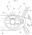
Fig. 1 is a schematic view schematically illustrating a state in which a cabin front portion of a vehicle according to an exemplary embodiment is viewed from the vehicle rear side. -
Fig. 2 is a block diagram illustrating hardware structures of a vehicle display control device according to the exemplary embodiment. -
Fig. 3 is a block diagram illustrating functional structures of the vehicle display control device according to the exemplary embodiment. -
Fig. 4 is a view illustrating an example of a display screen at a second display unit during autonomous driving, which is a view of a state in which there is no steering operation intervention or accelerator operation intervention. -
Fig. 5 is a view illustrating an example of a display screen at the second display unit during autonomous driving, which is a view of a state in which an accelerator operation intervention has been performed. -
Fig. 6 is a view illustrating an example of a display screen at the second display unit during autonomous driving, which is a view of a state in which a steering operation intervention has been performed. -
Fig. 7 is a view illustrating an example of a display screen during autonomous driving according to a variant example, which is a view of a state in which an accelerator operation intervention has been performed. -
Fig. 8 is a flowchart illustrating an example of a flow of display processing according to the exemplary embodiment. - A vehicle
display control device 10 according to an exemplary embodiment is employed in avehicle 12. Thevehicle 12 is described with reference to the drawings. As an example, thevehicle 12 according to the present exemplary embodiment is configured to be switchable between autonomous driving and manual driving. - As illustrated in
Fig. 1 , aninstrument panel 14 is provided at a front portion of a cabin interior of thevehicle 12. Theinstrument panel 14 extends in the vehicle width direction, and asteering wheel 16 is provided at the vehicle right side of theinstrument panel 14. That is, the present exemplary embodiment is an example of a right-hand drive car in which thesteering wheel 16 is provided at the right side and a driver seat is specified to be at the vehicle right side. - A
windshield glass 18 is provided at a front end portion of theinstrument panel 14. Thewindshield glass 18 extends in the vehicle vertical direction and the vehicle width direction, dividing the cabin interior from the cabin exterior. - A vehicle right side end portion of the
windshield glass 18 is fixed to a vehicle rightside front pillar 20. Thefront pillar 20 extends in the vehicle vertical direction, and thewindshield glass 18 is fixed to a vehicle width direction inner side end portion of thefront pillar 20. A front end portion of afront side glass 22 is fixed to a vehicle width direction outer side end portion of thefront pillar 20. A vehicle left side end portion of thewindshield glass 18 is fixed to a vehicle left side front pillar, which is not illustrated in the drawings. - A
first display section 24 is provided at thewindshield glass 18. Thefirst display section 24 is constituted by a projection surface that is projected onto by a head-updisplay device 23, which is illustrated inFig. 2 . Specifically, the head-updisplay device 23 is provided at the vehicle front side relative to theinstrument panel 14, and the head-updisplay device 23 is structured to project images onto thefirst display section 24 of thewindshield glass 18. - A
second display section 26 is provided at the vehicle lower side relative to thefirst display section 24. Thesecond display section 26 is a display section that is displayed in aninstrument cluster 25. Theinstrument cluster 25 is disposed at theinstrument panel 14 to the vehicle front of the driver seat. Thefirst display section 24 and thesecond display section 26 are provided at positions that are viewable by a driver. Thefirst display section 24 andsecond display section 26 correspond to a display unit of the present disclosure. The vehicle display system of the present disclosure is constituted by the vehicledisplay control device 10, thefirst display section 24 and thesecond display section 26. - As illustrated in
Fig. 2 , the vehicledisplay control device 10 according to the present exemplary embodiment includes an electronic control unit (ECU) 28. - The
ECU 28 includes a central processing unit (CPU or processor) 30, read-only memory (ROM) 32, random access memory (RAM) 34,storage 36 and an input/output interface 38. These structures are connected to be capable of communicating with one another via aninternal bus 39. - The CPU 30 is a central arithmetic processing unit that executes various programs and controls respective parts. That is, the CPU 30 reads a program from the
ROM 32 or thestorage 36, and executes the program using theRAM 34 as a workspace. The CPU 30 performs control of the structures described above and various kinds of computational processing in accordance with programs recorded in theROM 32 or thestorage 36. - The
ROM 32 stores various programs and various kinds of data. TheRAM 34 serves as a workspace, temporarily memorizing programs and data. Thestorage 36 is a non-transitory recording medium structured by a hard disk drive (HDD) or solid state drive (SSD). Thestorage 36 stores various programs, including an operating system, and various kinds of data. In the present exemplary embodiment, theROM 32 or thestorage 36 stores a display program and the like for implementing display processing. Various input/output devices are connected to the input/output interface 38. - The
ECU 28 is connected to anautonomous driving ECU 40. Similarly to theECU 28, the autonomous drivingECU 40 includes a CPU, ROM, RAM, storage and an input/output interface, which are not illustrated in the drawings. - A
sensor group 42 and anactuator group 44 are connected to the autonomous drivingECU 40. Thesensor group 42 detects current states of the vehicle. Theactuator group 44 controls running of the vehicle. Thesensor group 42 includes plural sensors among various sensors, such as cameras, radar, lidar (light detection and ranging or laser imaging detection and ranging), a GPS (global positioning system) sensor and so forth. The cameras image the vicinity of the vehicle. The radar detects distances and directions of objects in the vicinity of the vehicle with electromagnetic waves. The lidar detects distances and directions of objects in the vicinity of the vehicle with laser light. The GPS sensor detects a current position of the vehicle. Thesensor group 42 may also include sensors that detect states of vehicle occupants. For example, thesensor group 42 may include biosensors that detect pulse rates, levels of alertness and the like of vehicle occupants. - The
actuator group 44 includes acceleration and braking actuators that regulate acceleration and deceleration of the vehicle, and a steering actuator that drives a steering apparatus of the vehicle. Theautonomous driving ECU 40 implements autonomous driving of the vehicle by controlling operations of theactuator group 44 in accordance with current states of the vehicle detected by thesensor group 42. A planned route representing a route along which the vehicle plans to run is memorized in a memory section of the autonomous drivingECU 40. Theautonomous driving ECU 40 causes thevehicle 12 to run along the planned route memorized in the memory section. - The
ECU 28 is connected to anaccelerator position sensor 46 and asteering sensor 48. Theaccelerator position sensor 46 is a sensor that detects positions of an accelerator pedal, which is not illustrated in the drawings, that is provided at a lower portion of the driver seat. Thesteering sensor 48 is a sensor that detects loads applied to thesteering wheel 16 by a vehicle occupant. That is, thesteering sensor 48 according to the present exemplary embodiment does not detect loads when thesteering wheel 16 is being operated by theautonomous driving ECU 40 during autonomous driving, but detects loads when the vehicle occupant operates thesteering wheel 16. - The vehicle
display control device 10 uses the hardware resources described above to realize various functions. The functional structures realized by the vehicledisplay control device 10 are described with reference toFig. 3 . - As illustrated in
Fig. 3 , the vehicledisplay control device 10 includes, as functional structures, a drivingmode acquisition section 52, a vicinityinformation display section 54, an operationintervention detection section 56, adisplay change section 58 and awarning display section 60. The functional structures are realized by the CPU 30 of theECU 28 reading and executing a program. Functions of a display control section of the present disclosure include the functions of the vicinityinformation display section 54 and thedisplay change section 58. - The driving
mode acquisition section 52 acquires a driving mode of thevehicle 12, which is either of a manual driving mode and an autonomous driving mode. The manual driving mode according to the present exemplary embodiment signifies a driving mode in which thevehicle 12 runs via driving operations by a vehicle occupant. The autonomous driving mode according to the present exemplary embodiment signifies a driving mode in which thevehicle 12 runs independent of operations of thesteering wheel 16 by the vehicle occupant and accelerator operations. The drivingmode acquisition section 52 may acquire information relating to the driving mode on the basis of, for example, signals from the autonomous drivingECU 40. - At least when the driving mode acquired by the driving
mode acquisition section 52 is the autonomous driving mode, the vicinityinformation display section 54 constituting the display control section displays vicinity information of thevehicle 12 at thefirst display section 24 andsecond display section 26 provided in the cabin. More specifically, the vicinityinformation display section 54 acquires signals from thesensor group 42 and displays vicinity information of thevehicle 12 based on the acquired signals at thefirst display section 24 andsecond display section 26. -
Fig. 4 illustrates a portion of a display screen of thesecond display section 26 in the autonomous driving mode. As illustrated inFig. 4 , in the autonomous driving mode, a present vehicle image M1 representing thevehicle 12 is displayed at a lower portion of thesecond display section 26. A preceding vehicle image M2 representing a vehicle in front that is running ahead of thevehicle 12 is also displayed. A vicinity vehicle image M3 representing a nearby vehicle that is running in a lane adjacent to a lane in which thevehicle 12 is running is also displayed. The preceding vehicle image M2 and vicinity vehicle image M3 are displayed at thesecond display section 26 by the functioning of the vicinityinformation display section 54. When there is no vehicle in front or nearby vehicle within a predetermined range of thevehicle 12, the preceding vehicle image M2 and vicinity vehicle image M3 are not displayed at thesecond display section 26. - An image M4 indicating a current speed of the
vehicle 12 is displayed at an upper portion of thesecond display section 26. An image M5 indicating a set speed is displayed below the image M4. - Trajectory images M6 illustrating a planned running route of the
vehicle 12 and speed marks M7 corresponding to the speed of thevehicle 12 are displayed between the present vehicle image M1 and the preceding vehicle image M2. The trajectory images M6 are displayed in substantial strip shapes. When thevehicle 12 is proceeding straight ahead, the trajectory images M6 are displayed in substantially linear shapes in the vertical direction. Although not illustrated in the drawings, when thevehicle 12 is turning left or right and when thevehicle 12 is curving along a bend in the road, the trajectory images M6 are displayed in states that curve along the planned running route of thevehicle 12. The trajectory images M6 are displayed at thesecond display section 26 by the functioning of the vicinityinformation display section 54. - A plural number of the speed marks M7 are displayed spaced apart in a state in which the speed marks M7 are superposed with the trajectory images M6. In
Fig. 4 , four of the speed marks M7 are displayed. The speed marks M7 are displayed such that spacings thereof change in accordance with speeds of thevehicle 12. For example, when the speed of thevehicle 12 is a lower speed than inFig. 4 , the speed marks M7 are displayed with smaller spacings. Conversely, when the speed of thevehicle 12 is a higher speed than inFig. 4 , the speed marks M7 are displayed with larger spacings. The speed marks M7 are displayed at thesecond display section 26 by the functioning of the vicinityinformation display section 54. - The
first display section 24 displays similar images to thesecond display section 26. In the present exemplary embodiment, because a display region of thefirst display section 24 is narrower than a display region of thesecond display section 26, only some of the images in thesecond display section 26 are displayed in thefirst display section 24. For example, the preceding vehicle image M2, trajectory images M6 and speed marks M7 are displayed in thefirst display section 24. - When the driving mode acquired by the driving
mode acquisition section 52 is the autonomous driving mode, the operationintervention detection section 56 illustrated inFig. 3 detects driving operation interventions by the vehicle occupant. That is, the operationintervention detection section 56 functions only when the driving mode is the autonomous driving mode and does not function when the driving mode is the manual driving mode. In the autonomous driving mode, when the operationintervention detection section 56 detects that the accelerator pedal has moved from an initial position thereof on the basis of signals from theaccelerator position sensor 46, the operationintervention detection section 56 determines that an accelerator operation intervention by the vehicle occupant has occurred. Further, in the autonomous driving mode, when the operationintervention detection section 56 detects that the vehicle occupant has applied a load to thesteering wheel 16 on the basis of signals from thesteering sensor 48, the operationintervention detection section 56 determines that a steering operation intervention by the vehicle occupant has occurred. - When a driving operation intervention by the vehicle occupant is detected by the operation
intervention detection section 56, thedisplay change section 58 constituting the display control section changes a background color of the vicinity information of thevehicle 12 that is displayed at thefirst display section 24 and thesecond display section 26. - As an example in the present exemplary embodiment, when the operation
intervention detection section 56 detects a driving operation intervention, thedisplay change section 58 changes the background color of thefirst display section 24 and thesecond display section 26 as illustrated inFig. 5 , from the state illustrated inFig. 4 . The background color is not particularly limited; thedisplay change section 58 changes the background color such that the vehicle occupant may be alerted. - For example, as illustrated in
Fig. 4 , in a state in which no driving operation intervention has been detected, the background color of thesecond display section 26 is in an uncolored state. In contrast, as illustrated inFig. 5 , when a driving operation intervention has been detected, thedisplay change section 58 tones down the background color of thesecond display section 26 to a gray. In this case, the present vehicle image M1 and lanes are not toned down; only the surrounding color is toned down. - When an accelerator operation is detected by the operation
intervention detection section 56, thedisplay change section 58 displays the vehicle in front with a toned down color. In addition, when the accelerator operation is detected by the operationintervention detection section 56, thedisplay change section 58 stops display of the speed marks M7. -
Fig. 5 is a display screen of thesecond display section 26 in a state in which an accelerator operation intervention has been performed during autonomous driving. As illustrated inFig. 5 , the color of the preceding vehicle image M2 is toned down by thedisplay change section 58. The preceding vehicle image M2 being displayed in a toned down color displays the fact that a driving assistance function that automatically regulates the distance from the vehicle in front has stopped operating. - In addition, the speed marks M7 that are displayed superposed with the trajectory images M6 of the planned running route are hidden by the
display change section 58. This displays the fact that, because the vehicle occupant has a foot on the accelerator pedal, the speed of thevehicle 12 is not being controlled. - When an accelerator operation intervention is performed during autonomous driving, the
display change section 58 tones down the image M5 of the set speed. This displays the fact that a set speed function has stopped operating. - When a steering operation intervention is detected by the operation
intervention detection section 56, thedisplay change section 58 stops display of the trajectory images M6.Fig. 6 is a display screen of thesecond display section 26 in a state in which a steering operation intervention has been performed during autonomous driving. As illustrated inFig. 6 , the trajectory images M6 are hidden by thedisplay change section 58. In association with the hiding of the trajectory images M6, the speed marks M7 are also hidden. - In
Fig. 6 , the preceding vehicle image M2 is not toned down but displayed the same as inFig. 4 . That is, because no accelerator operation intervention has been performed inFig. 6 , the driving assistance function that regulates the distance from the vehicle in front is operating. Meanwhile, because thesteering wheel 16 is being operated, the fact that a function for running along the planned running route has stopped operating is displayed. - When a steering operation intervention or an accelerator operation intervention is detected by the operation
intervention detection section 56, thewarning display section 60 illustrated inFig. 3 displays a warning representing the driving operation intervention at thefirst display section 24 and thesecond display section 26. - As illustrated in
Fig. 5 andFig. 6 , when one or both of a steering operation intervention and an accelerator operation intervention is performed, a warning image M8 is displayed at the left side of the image M4 displaying the speed of thevehicle 12. The warning image M8 according to the present exemplary embodiment is, for example, an image representing a state in which the steering wheel is being held, but this is not limiting. For example, the variant example illustrated inFig. 7 may be displayed. -
Fig. 7 illustrates a variant example of the display screen of thesecond display section 26 in a state in which an accelerator operation intervention has been performed during autonomous driving. As illustrated inFig. 7 , the preceding vehicle image M2 and the set speed image M5 are displayed toned down by thedisplay change section 58. Thewarning display section 60 displays a warning image M9 at the left side of the image M4 illustrating the speed of thevehicle 12. The warning image M9 is an image of a foot stepping on the accelerator pedal. Thus, thewarning display section 60 may implement different displays when a steering operation is detected by the operationintervention detection section 56 and when an accelerator operation is detected. - Now, operation of the present exemplary embodiment is described.
-
Fig. 8 is a flowchart illustrating an example of flow of the display processing by the vehicledisplay control device 10. This display processing is implemented by the CPU 30 of theECU 28 reading a program from theROM 32 orstorage 36, loading the program into theRAM 34, and executing the program. - As illustrated in
Fig. 8 , in step S102, the CPU 30 acquires the driving mode. More specifically, by the functioning of the drivingmode acquisition section 52, the CPU 30 acquires the driving mode of thevehicle 12, which is either of the manual driving mode and the autonomous driving mode. - In step S104, the CPU 30 makes a determination as to whether the driving mode of the
vehicle 12 is the autonomous driving mode. When the driving mode of thevehicle 12 acquired by the drivingmode acquisition section 52 is the autonomous driving mode, the result of the determination in step S104 is affirmative and the CPU 30 proceeds to the processing of step S106. On the other hand, when the driving mode of thevehicle 12 acquired by the drivingmode acquisition section 52 is the manual driving mode, the CPU 30 ends the display processing. - In step S106, the CPU 30 displays vicinity information. More specifically, by the functioning of the vicinity
information display section 54, the CPU 30 acquires signals from thesensor group 42 and displays vicinity information of thevehicle 12 based on the acquired signals at thefirst display section 24 andsecond display section 26. For example, in step S106, the CPU 30 displays the present vehicle image M1, preceding vehicle image M2, vicinity vehicle image M3, trajectory images M6, speed marks M7 and the like at thesecond display section 26 as illustrated inFig. 4 . The CPU 30 displays similar images to thesecond display section 26 at thefirst display section 24. - In step S108, the CPU 30 makes a determination as to whether an accelerator operation intervention has been performed. More specifically, by the functioning of the operation
intervention detection section 56, when the CPU 30 detects an accelerator operation intervention on the basis of signals from theaccelerator position sensor 46, the result of the determination in step S108 is affirmative and the CPU 30 proceeds to the processing of step S110. - On the other hand, when the CPU 30 does not detect an accelerator operation intervention by the functioning of the operation
intervention detection section 56 in step S108, the result of the determination in step S108 is negative and the CPU 30 proceeds to the processing of step S112. - In step S110, the CPU 30 implements a display for a time of accelerator operation intervention. More specifically, by the functioning of the
display change section 58, the CPU 30 changes the background color of thesecond display section 26 as illustrated inFig. 5 . In addition, by the functioning of thedisplay change section 58, the CPU 30 tones down the displays of the preceding vehicle image M2 and the set speed image M5, and hides display of the speed marks M7. Further in step S110, by the functioning of thewarning display section 60, the CPU 30 displays the warning image M8. Although not illustrated in the drawings, similar changes are applied to the display at thefirst display section 24. - In step S112, the CPU 30 makes a determination as to whether a steering operation intervention has been performed. More specifically, by the functioning of the operation
intervention detection section 56, when the CPU 30 detects a steering operation intervention on the basis of signals from thesteering sensor 48, the result of the determination in step S112 is affirmative and the CPU 30 proceeds to the processing of step S114. - On the other hand, when the CPU 30 does not detect a steering operation intervention by the functioning of the operation
intervention detection section 56 in step S112, the result of the determination in step S112 is negative and the CPU 30 ends the display processing. - In step S114, the CPU 30 implements a display for a time of steering operation intervention. More specifically, by the functioning of the
display change section 58, the CPU 30 changes the background color of thesecond display section 26 as illustrated inFig. 6 . In addition, by the functioning of thedisplay change section 58, the CPU 30 hides display of the trajectory images M6 illustrating the planned running route and the speed marks M7. Further in step S114, by the functioning of thewarning display section 60, the CPU 30 displays the warning image M8. Although not illustrated in the drawings, similar changes are applied to the display at thefirst display section 24. The CPU 30 then ends the display processing. - The state illustrated in
Fig. 6 is a display when the result of the determination in step S108 is negative and the result of the determination in step S112 is affirmative. That is,Fig. 6 illustrates a display example for a situation in which there is no accelerator operation intervention but a steering operation intervention is performed. Alternatively, when the result of the determination instep S 108 is affirmative and the result of the determination step S112 is affirmative, that is, when interventions by both accelerator operation and steering operation have been performed, the display ofFig. 5 and the display ofFig. 6 are combined. In this situation, by the functioning of thedisplay change section 58, the CPU 30 changes the background color of thesecond display section 26 as illustrated inFig. 5 andFig. 6 . In addition, by the functioning of thedisplay change section 58, the CPU 30 tones down the displays of the preceding vehicle image M2 and the set speed image M5, and hides display of the trajectory images M6 illustrating the planned running route and the speed marks M7. Further, by the functioning of thewarning display section 60, the CPU 30 displays the warning image M8. - As described above, in the vehicle
display control device 10 according to the present exemplary embodiment, at least when the driving mode acquired by the driving mode acquisition section is the autonomous driving mode, the vicinityinformation display section 54 displays vicinity information of thevehicle 12 at thefirst display section 24 and thesecond display section 26. Thus, in the autonomous driving mode, a vehicle occupant may check vicinity information of thevehicle 12 by looking at thefirst display section 24 and thesecond display section 26. - In the present exemplary embodiment, when a driving operation intervention is detected by the operation
intervention detection section 56, thedisplay change section 58 changes background information of the vicinity information of thevehicle 12 displayed at thefirst display section 24 andsecond display section 26. Therefore, if a vehicle occupant unintentionally performs a driving operation during running in the autonomous driving mode, because the backgrounds of thefirst display section 24 andsecond display section 26 change, the driving operation intervention may be reported to the vehicle occupant visually. For example, if the vehicle occupant unintentionally places a foot on the accelerator pedal and presses the accelerator pedal, an alert may be given that an accelerator operation intervention has been performed. - In the present exemplary embodiment, because the alert is given to the vehicle occupant visually, disturbance of the comfort of another vehicle occupant may be suppressed compared to a configuration that frequently gives reports by voice messages.
- In the present exemplary embodiment, because the vicinity
information display section 54 displays the planned running route at thefirst display section 24 and thesecond display section 26, the vehicle occupant may understand the planned running route at a glance when in the autonomous driving mode. Because thedisplay change section 58 stops display of the image M5 of the planned running route when there is a steering operation intervention, the vehicle occupant may be made aware that thesteering wheel 16 has been operated. - In the present exemplary embodiment, because the vicinity
information display section 54 displays the preceding vehicle image M2 at thefirst display section 24 and thesecond display section 26, the vehicle occupant may understand at a glance that there is a vehicle in front when in the autonomous driving mode. Because thedisplay change section 58 displays the preceding vehicle image M2 with the color toned down when there is an accelerator operation intervention, the vehicle occupant may be made aware that an accelerator operation has been performed. - In the present exemplary embodiment, because the vicinity
information display section 54 displays the speed marks M7 at thefirst display section 24 and thesecond display section 26, the vehicle occupant may check the speed of thevehicle 12 in the autonomous driving mode just by checking the spacing of the speed marks M7. Because thedisplay change section 58 stops display of the speed marks M7 when there is an accelerator operation intervention, the vehicle occupant may be made aware that an accelerator operation has been performed. - In the present exemplary embodiment, because the warning image M8 is displayed at the
first display section 24 and thesecond display section 26 by thewarning display section 60, the occurrence of a driving operation intervention may be reported to the vehicle occupant effectively. When, as in the variant example illustrated inFig. 7 , the warning image is altered between a time of an accelerator operation intervention and a time of a steering operation intervention, the vehicle occupant may understand the kind of driving operation easily. - The vehicle
display control device 10 according to the exemplary embodiment is described above, but it will be clear that numerous modes may be embodied within a scope that does not depart from the gist of the present disclosure. For example, in the exemplary embodiment described above, thedisplay change section 58 is configured to change the background information of thefirst display section 24 and thesecond display section 26 when there is an accelerator operation intervention and when there is a steering operation intervention, but this is not limiting. The background information of thefirst display section 24 and thesecond display section 26 may be changed when there is an alternative driving operation. For example, thedisplay change section 58 may change the background information of thefirst display section 24 and thesecond display section 26 when a direction indicator is operated, and thedisplay change section 58 may change the background of thefirst display section 24 and thesecond display section 26 when a brake pedal is pressed. - In the exemplary embodiment described above, an accelerator operation intervention is detected on the basis of signals from the
accelerator position sensor 46, but this is not limiting. For example, in a vehicle in which acceleration and deceleration are performed by operation of an operation section such as a button and a lever or the like instead of an accelerator pedal, an accelerator operation intervention may be detected on the basis of signals from that operation section. - In the exemplary embodiment described above, a steering operation intervention is detected on the basis of signals from the
steering sensor 48, but this is not limiting. For example, in a vehicle in which steering is performed by operation of an operation section such as a button and a lever or the like instead of thesteering wheel 16, a steering operation intervention may be detected on the basis of signals from that operation section. - In the exemplary embodiment described above, vicinity information of the vehicle is displayed at both the
first display section 24 and thesecond display section 26, but this is not limiting. For example, a configuration is possible in which the vicinityinformation display section 54 displays the vicinity information of the vehicle only at thefirst display section 24. - In the exemplary embodiment described above, the
display change section 58 changes the background color of the whole of thesecond display section 26, but this is not limiting. For example, a configuration in which thedisplay change section 58 changes the background color of a portion of thesecond display section 26 may provide the same effects as the exemplary embodiment described above, provided a vehicle occupant may be alerted to a driving operation intervention. - In the exemplary embodiment described above, the
display change section 58 changes the background color of thefirst display section 24 and thesecond display section 26 when there is a driving operation intervention, but this is not limiting. For example, thedisplay change section 58 may change the background information by displaying a predetermined pattern in the backgrounds of thefirst display section 24 and thesecond display section 26 when there is a driving operation intervention.
Claims (11)
- A vehicle display control device (10) comprising:a driving mode acquisition section (52) that is configured to acquire information on which of a manual driving mode or an autonomous driving mode is a driving mode,the vehicle running via driving operations by a vehicle occupant in the manual driving mode, andthe vehicle running independent of driving operations by the vehicle occupant in the autonomous driving mode;an operation intervention detection section (56) that, in a case in which the driving mode acquired by the driving mode acquisition section is the autonomous driving mode, is configured to detect a driving operation intervention by the vehicle occupant; anda display control section (54, 58) that is configured to display vicinity information of the vehicle at a display unit (24, 26) provided at a vehicle cabin at least in a case in which the driving mode acquired by the driving mode acquisition section (52) is the autonomous driving mode,wherein, in a case in which a driving operation intervention is detected by the operation intervention detection section (56), the display control section (54, 58) is configured to change background information of the vicinity information and to display the background information at the display unit (24, 26).
- The vehicle display control device according to claim 1, wherein the operation intervention detection section (56) is configured to detect, as a driving operation intervention, at least one of a steering operation by the vehicle occupant or an accelerator operation by the vehicle occupant.
- The vehicle display control device according to claim 2, wherein the display control section (54) is configured to display a planned running route (M6) of the vehicle at the display unit (24, 26) and, in a case in which a steering operation is detected by the operation intervention detection section (56), the display control section (54) is configured to hide display of the planned running route (M6).
- The vehicle display control device according to claim 3, wherein the planned running route (M3) is displayed superposed on an image of a driving lane of the vehicle.
- The vehicle display control device according to any one of claims 2 to 4, wherein:the display control section (54) is configured to display a preceding vehicle (M2) at the display unit (24, 26), andin a case in which an accelerator operation is detected by the operation intervention detection section (56), the display control section (54) is configured to tone down a color of the preceding vehicle (M2) and to display the preceding vehicle (M2).
- The vehicle display control device according to any one of claims 2 to 5, wherein:the display control section (54) is configured to display speed marks (M7) at the display unit (24, 26), a spacing of the speed marks (M7) changing in accordance with a speed of the vehicle, andin a case in which an accelerator operation is detected by the operation intervention detection section (56), the display control section (54) is configured to hide display of the speed marks (M7).
- The vehicle display control device according to any one of claims 2 to 6, further comprising a warning display section (60) that, in a case in which at least one of a steering operation or an accelerator operation is detected by the operation intervention detection section (56), is configured to display a warning image (M8, M9) representing the driving operation intervention at the display unit (24, 26).
- The vehicle display control device according to claim 7, wherein the warning display section (60) is configured to display different warning images (M8, M9) in a case in which a steering operation is detected by the operation intervention detection section (56) and in a case in which an accelerator operation is detected.
- A vehicle display system comprising:the vehicle display control device according to any one of claims 1 to 8; andthe display unit (24, 26) being intended to be provided at the vehicle cabin, vicinity information of the vehicle being displayed at the display unit (24, 26).
- A vehicle display control method comprising:acquiring (S102) information on which of a manual driving mode or an autonomous driving mode is a driving mode,a vehicle running via driving operations by a vehicle occupant in the manual driving mode, andthe vehicle running independent of driving operations by the vehicle occupant in the autonomous driving mode;in a case in which the acquired driving mode is the autonomous driving mode, detecting (S108, S112) a driving operation intervention by the vehicle occupant;at least in a case in which the acquired driving mode is the autonomous driving mode, displaying (S106) vicinity information of the vehicle at a display unit (24, 26) provided at a vehicle cabin; andin a case in which a driving operation intervention is detected, changing (S110, S114) background information of the vicinity information and displaying the background information at the display unit (24, 26).
- A non-transitory storage medium storing a program causing a computer to execute processing comprising:acquiring (S102) information on which of a manual driving mode or an autonomous driving mode is a driving mode,a vehicle running via driving operations by a vehicle occupant in the manual driving mode, andthe vehicle running independent of driving operations by the vehicle occupant in the autonomous driving mode;in a case in which the acquired driving mode is the autonomous driving mode, detecting (S108, S112) a driving operation intervention by the vehicle occupant;at least in a case in which the acquired driving mode is the autonomous driving mode, displaying (S106) vicinity information of the vehicle at a display unit (24, 26) provided at a vehicle cabin; andin a case in which a driving operation intervention is detected, changing (S110, S114) background information of the vicinity information and displaying the background information at the display unit (24, 26).
Applications Claiming Priority (1)
| Application Number | Priority Date | Filing Date | Title |
|---|---|---|---|
| JP2020146390A JP7439701B2 (en) | 2020-08-31 | 2020-08-31 | Vehicle display control device, vehicle display system, vehicle display control method and program |
Publications (1)
| Publication Number | Publication Date |
|---|---|
| EP3960516A1 true EP3960516A1 (en) | 2022-03-02 |
Family
ID=77518967
Family Applications (1)
| Application Number | Title | Priority Date | Filing Date |
|---|---|---|---|
| EP21193189.4A Pending EP3960516A1 (en) | 2020-08-31 | 2021-08-26 | Vehicle display control device, vehicle display system, vehicle display control method, and non-transitory storage medium |
Country Status (4)
| Country | Link |
|---|---|
| US (1) | US20220063404A1 (en) |
| EP (1) | EP3960516A1 (en) |
| JP (6) | JP7439701B2 (en) |
| CN (1) | CN114103976A (en) |
Families Citing this family (2)
| Publication number | Priority date | Publication date | Assignee | Title |
|---|---|---|---|---|
| US10888383B2 (en) * | 2018-07-17 | 2021-01-12 | Verb Surgical Inc. | Robotic surgical pedal with integrated foot sensor |
| JP2024053916A (en) * | 2022-10-04 | 2024-04-16 | カワサキモータース株式会社 | Vehicular display system, vehicle and display method of the same |
Family Cites Families (13)
| Publication number | Priority date | Publication date | Assignee | Title |
|---|---|---|---|---|
| US6324463B1 (en) * | 1998-05-12 | 2001-11-27 | C. Kumar N. Patel | Cruise control indicator |
| JP4239771B2 (en) * | 2003-09-18 | 2009-03-18 | 日産自動車株式会社 | VEHICLE DRIVE OPERATION ASSISTANCE DEVICE AND VEHICLE HAVING VEHICLE DRIVE OPERATION ASSISTANCE DEVICE |
| JP4716139B2 (en) * | 2008-05-14 | 2011-07-06 | アイシン精機株式会社 | Perimeter monitoring device |
| US9374562B2 (en) * | 2011-04-19 | 2016-06-21 | Ford Global Technologies, Llc | System and method for calculating a horizontal camera to target distance |
| US20170190286A1 (en) * | 2016-01-03 | 2017-07-06 | Edward Yavitz | GPS Vehicle Speed and Velocity Change Indicator |
| JP6414096B2 (en) * | 2016-02-17 | 2018-10-31 | トヨタ自動車株式会社 | In-vehicle device, control method for in-vehicle device, and control program for in-vehicle device |
| US9697655B1 (en) * | 2016-03-16 | 2017-07-04 | Christopher Eyhorn | Engine failure detection system |
| JP6964271B2 (en) * | 2016-03-31 | 2021-11-10 | パナソニックIpマネジメント株式会社 | Driving support method and driving support device, automatic driving control device, vehicle, program using it |
| JP6795457B2 (en) * | 2017-06-02 | 2020-12-02 | 本田技研工業株式会社 | Vehicle control systems, vehicle control methods, and vehicle control programs |
| JP6825710B2 (en) * | 2017-08-25 | 2021-02-03 | 日産自動車株式会社 | Surrounding vehicle display method and surrounding vehicle display device |
| JP6954850B2 (en) * | 2018-02-09 | 2021-10-27 | トヨタ自動車株式会社 | Display device |
| JP7151393B2 (en) * | 2018-11-08 | 2022-10-12 | トヨタ自動車株式会社 | Vehicle information providing device, vehicle information providing method and program |
| JP2020091589A (en) * | 2018-12-04 | 2020-06-11 | 株式会社デンソー | Drive recorder |
-
2020
- 2020-08-31 JP JP2020146390A patent/JP7439701B2/en active Active
-
2021
- 2021-07-20 CN CN202110818380.XA patent/CN114103976A/en active Pending
- 2021-07-26 US US17/384,916 patent/US20220063404A1/en active Pending
- 2021-08-26 EP EP21193189.4A patent/EP3960516A1/en active Pending
-
2023
- 2023-10-26 JP JP2023184196A patent/JP2023181336A/en active Pending
- 2023-10-26 JP JP2023184197A patent/JP2023181337A/en active Pending
- 2023-10-26 JP JP2023184195A patent/JP2023181335A/en active Pending
- 2023-10-26 JP JP2023184198A patent/JP2023181338A/en active Pending
- 2023-10-26 JP JP2023184199A patent/JP2023178481A/en active Pending
Also Published As
| Publication number | Publication date |
|---|---|
| JP2023178481A (en) | 2023-12-14 |
| CN114103976A (en) | 2022-03-01 |
| JP2023181338A (en) | 2023-12-21 |
| JP2023181337A (en) | 2023-12-21 |
| JP7439701B2 (en) | 2024-02-28 |
| US20220063404A1 (en) | 2022-03-03 |
| JP2022041285A (en) | 2022-03-11 |
| JP2023181336A (en) | 2023-12-21 |
| JP2023181335A (en) | 2023-12-21 |
Similar Documents
| Publication | Publication Date | Title |
|---|---|---|
| CN110304052B (en) | Method for calculating insertion of additional information, device for carrying out the method and motor vehicle | |
| US9649936B2 (en) | In-vehicle device, control method of in-vehicle device, and computer-readable storage medium | |
| US20190248287A1 (en) | Display device | |
| US11325471B2 (en) | Method for displaying the course of a safety zone in front of a transportation vehicle or an object by a display unit, device for carrying out the method, and transportation vehicle and computer program | |
| US10600257B2 (en) | Method and apparatus for monitoring of an autonomous vehicle | |
| WO2018198847A1 (en) | Driving assistance device and driving assistance program | |
| EP3960516A1 (en) | Vehicle display control device, vehicle display system, vehicle display control method, and non-transitory storage medium | |
| US11782518B2 (en) | Vehicle information display system | |
| WO2020003750A1 (en) | Vehicle display control device, vehicle display control method, and control program | |
| EP3667641A1 (en) | Vehicle driving assistance system, vehicle driving assistance method, and vehicle driving assistance program | |
| CN110626265B (en) | Periphery monitoring device | |
| US20230373309A1 (en) | Display control device | |
| JP6990221B2 (en) | Vehicle and its control device and control method | |
| CN115867454A (en) | Display control device for vehicle, display control system for vehicle, and display control method for vehicle | |
| JP2005181277A (en) | Speed display apparatus | |
| EP4414200A2 (en) | Vehicle display device, vehicle display method, and non-transitory storage medium | |
| US12024015B2 (en) | Display control device for a vehicle, display method, program, and display system for a vehicle | |
| US20240317056A1 (en) | Display control device for a vehicle, display method, program, and display system for a vehicle | |
| US11760362B2 (en) | Positive and negative reinforcement systems and methods of vehicles for driving | |
| US20240083246A1 (en) | Display control device, display control method, non-transitory computer-readable medium storing a program | |
| US20230087958A1 (en) | Vehicular display device, vehicle, display method, and non-transitory computer-readable medium storing program | |
| US20240246419A1 (en) | Vehicle display control device, vehicle, vehicle display control method, and non-transitory storage medium | |
| JP2005352816A (en) | Vehicular information presenting device and vehicular information presenting method | |
| JP2024112709A (en) | Vehicle display device, vehicle display method, and vehicle display program | |
| SE1250342A1 (en) | Procedures and systems for improving the safety of driving a motor vehicle |
Legal Events
| Date | Code | Title | Description |
|---|---|---|---|
| PUAI | Public reference made under article 153(3) epc to a published international application that has entered the european phase |
Free format text: ORIGINAL CODE: 0009012 |
|
| STAA | Information on the status of an ep patent application or granted ep patent |
Free format text: STATUS: REQUEST FOR EXAMINATION WAS MADE |
|
| 17P | Request for examination filed |
Effective date: 20210826 |
|
| AK | Designated contracting states |
Kind code of ref document: A1 Designated state(s): AL AT BE BG CH CY CZ DE DK EE ES FI FR GB GR HR HU IE IS IT LI LT LU LV MC MK MT NL NO PL PT RO RS SE SI SK SM TR |